JP2006507965A - propeller - Google Patents
propeller Download PDFInfo
- Publication number
- JP2006507965A JP2006507965A JP2004501250A JP2004501250A JP2006507965A JP 2006507965 A JP2006507965 A JP 2006507965A JP 2004501250 A JP2004501250 A JP 2004501250A JP 2004501250 A JP2004501250 A JP 2004501250A JP 2006507965 A JP2006507965 A JP 2006507965A
- Authority
- JP
- Japan
- Prior art keywords
- wing
- propeller
- support structure
- aerodynamic
- grid
- Prior art date
- Legal status (The legal status is an assumption and is not a legal conclusion. Google has not performed a legal analysis and makes no representation as to the accuracy of the status listed.)
- Pending
Links
Images


Classifications
-
- B—PERFORMING OPERATIONS; TRANSPORTING
- B63—SHIPS OR OTHER WATERBORNE VESSELS; RELATED EQUIPMENT
- B63H—MARINE PROPULSION OR STEERING
- B63H1/00—Propulsive elements directly acting on water
- B63H1/02—Propulsive elements directly acting on water of rotary type
- B63H1/12—Propulsive elements directly acting on water of rotary type with rotation axis substantially in propulsive direction
- B63H1/14—Propellers
- B63H1/26—Blades
Abstract
支持翼桁の3次元構造体を除いては概ね中空である構造体を提供するために、格子ブロック材料を使用してプロペラ又はプロペラ翼を製造する。このプロペラ又はプロペラ翼は大部分が中空であるので、支持翼桁の3次元格子のため所望の強度を保持しながら、中実のプロペラ又はプロペラ翼に比べ相当に軽くなる。Propellers or propeller blades are manufactured using lattice block material to provide a structure that is generally hollow except for the three-dimensional structure of the support spar. Since this propeller or propeller blade is mostly hollow, it is considerably lighter than a solid propeller or propeller blade, while maintaining the desired strength due to the three-dimensional grid of support spar.
Description
本出願は2002年4月29日出願の米国特許仮出願第60/375,713号明細書の優先権を主張しており、その明細書全体を参考として本明細書に援用する。 This application claims priority from US Provisional Application No. 60 / 375,713 filed Apr. 29, 2002, which is hereby incorporated by reference in its entirety.
本発明は、プロペラ及びプロペラを製造する方法、より詳細には格子ブロック材料を使用して製造するプロペラに関する。 The present invention relates to propellers and methods for manufacturing propellers, and more particularly to propellers manufactured using lattice block materials.
舶用プロペラは極めて大きく、しばしば直径3.0m(10フィート)を超え、通常は青銅合金によって製造される。プロペラは単一の鋳造物として製造することができる。又は、通常はそれぞれが中実の鋳造物の構成部品である、別々に鋳造した複数の翼を次いで別の中央ハブに取り付けるように設計することもできる。このサイズと材料の組合せによって、プロペラは極めて重くなり、この重量を支えなければならない翼取り付け部品、主軸及び主軸軸受に大きな機械的応力を課す。より大きなプロペラの重量は、そのような構成部品に過大な応力を付与するので、プロペラはある用途に所望されるよりも小さい直径に制限されることさえある。大きなプロペラ、中実鋳造プロペラ及びプロペラ翼はまた、材料の断面寸法が非常に大きいので、材料が凝固すると、断面の微細構造が最適ではなくなり、引張強度、降伏強度、伸び、疲労寿命などの機械的強度特性が減少する。 Marine propellers are extremely large, often exceeding 10 feet in diameter and are usually made of bronze alloys. The propeller can be manufactured as a single casting. Alternatively, a plurality of separately cast wings, each usually a solid cast component, can be designed to then be attached to another central hub. This combination of size and material makes the propeller extremely heavy and imposes significant mechanical stress on the wing fittings, spindle and spindle bearings that must support this weight. Larger propeller weights can place too much stress on such components, so propellers may even be limited to smaller diameters than desired for certain applications. Large propellers, solid cast propellers and propeller blades also have very large cross-sectional dimensions of the material, so when the material solidifies, the cross-sectional microstructure becomes sub-optimal, and machines such as tensile strength, yield strength, elongation, fatigue life, etc. The strength characteristics are reduced.
そのような欠点に対処する、特にプロペラの重量を減少させる試みによって、翼の厚さは翼弦長に対して相対的に減少してきている。しかし、この結果プロペラのキャビテーション性能が悪化し、機械的強度特性が減少する可能性がある。 In an attempt to address such shortcomings, particularly reducing the weight of the propeller, the blade thickness has decreased relative to the chord length. However, as a result, the cavitation performance of the propeller may be deteriorated and the mechanical strength characteristics may be reduced.
さらに、従来のプロペラは、一般にプロペラ翼の材料の質量及び特性に起因する、固定のモード/振動特性を有する。そのようなプロペラは、1枚または複数の翼に材料を加え、又は翼から材料を削除してバランスをとることができるが、プロペラの性能及び構造的完全性を保ちながらそのようなバランスをとることができるやり方には限界がある。 Furthermore, conventional propellers have fixed mode / vibration characteristics, generally due to the mass and characteristics of the propeller blade material. Such propellers can be balanced by adding material to or removing material from one or more wings, but do so while maintaining propeller performance and structural integrity. There are limits to how you can do it.
翼桁間の間隔が中空である、支持翼桁の連続する3次元格子を有する鋳造物、時折格子ブロック材料又はLBMと称される鋳造物を作り出す1種の鋳造技術がマサチューセッツ州WilmingtonのJonathan Aerospace Materials Corporationによって開発されてきた。そのような技術は、例えば、「3次元構造物体を鋳造するための方法及び装置」という名称の、1999年11月4日公開の国際特許公報のWO第99/55476号パンフレットに開示されており、その明細書の内容を参考として本明細書で援用する。経済的でかつ製造される物体が容易に再利用又は製造されうる形態で鋳造することができる、3次元構造物体を鋳造する装置及び方法を提供するために、本発明は、各々が事実上角柱の形状を有し、軸線に対し平行な或いは少し先細りになった少なくとも3枚の壁を有する、いくつかのコア(1;31、32)を備える装置を提供する。コアは公知の鋳物砂成分で構成される。角柱の形状及び断面形状は、いくつかのコア(1;31、32)が実質的に密接して空間を埋めるように、その角柱面(2、3、4)によって並置することができるように選択される。角柱の表面(2、3、4)の少なくとも一部分には、コア(1;31、32)が組み立てられたとき連続した構造体を形成する凹部又は鋳造溝(6、7、8、9)が存在する。この方法では、その中空形状が角柱形状の断面を有するいくつかのコアにより、角柱表面が事実上密集、密着して互いに向き合い、角柱表面の凹部が鋳造すべき構造物(翼桁)を画成し、コアが、用意された鋳造空間を事実上完全に充填するように構成される。 Jonathan Aerospace in Wilmington, Massachusetts is a casting technology that produces castings with a continuous three-dimensional grid of support spars, sometimes called slab block material or LBM, where the spacing between the spars is hollow. Developed by Materials Corporation. Such a technique is disclosed, for example, in the pamphlet of WO 99/55476 published on Nov. 4, 1999, entitled “Method and apparatus for casting three-dimensional structural objects”. The contents of the specification are incorporated herein by reference. In order to provide an apparatus and method for casting a three-dimensional structure object that can be cast in a form that is economical and can be easily reused or manufactured, the present invention is essentially a prism And a device comprising several cores (1; 31, 32) having at least three walls parallel to the axis or slightly tapered. The core is composed of a known foundry sand component. The shape and cross-sectional shape of the prisms can be juxtaposed by their prism surfaces (2, 3, 4) so that several cores (1; 31, 32) fill the space substantially closely. Selected. At least a portion of the prismatic surface (2, 3, 4) has recesses or cast grooves (6, 7, 8, 9) that form a continuous structure when the core (1; 31, 32) is assembled. Exists. In this method, a hollow core has a prismatic cross section, and the prismatic surfaces are effectively densely packed and closely contact each other, and the concave portions on the prismatic surface define a structure (blade girder) to be cast. And the core is configured to substantially completely fill the prepared casting space.
本発明は、支持翼桁の3次元格子を除き概ね中空である構造体を提供するために、格子ブロック材料を使用して製造されるプロペラ又はプロペラ翼である。このプロペラ又はプロペラ翼は、大部分が中空であるので、支持翼桁の3次元格子によって所望の強度を保持しながら、中実鋳造のプロペラ又はプロペラ翼よりも大幅に軽くなる。 The present invention is a propeller or propeller blade manufactured using a grid block material to provide a structure that is generally hollow except for a three-dimensional grid of support spar. Since this propeller or propeller blade is largely hollow, it is significantly lighter than a solid cast propeller or propeller blade while maintaining the desired strength by the three-dimensional grid of support spar.
本発明の一目的は、実質的に中空であり、相当する中実の構成部品よりも大幅に軽いが、LBM格子の内部補強に起因して所望の強度を保持する、鋳造プロペラ、プロペラ翼又は他の構成部品を提供することである。 One object of the present invention is a cast propeller, propeller blade or propeller that is substantially hollow and significantly lighter than the corresponding solid component, but retains the desired strength due to the internal reinforcement of the LBM grid. It is to provide other components.
本発明の別の目的は、プロペラの重量を支持しなければならない翼取り付け構成部品、主軸、及び主軸軸受に付与される応力を低減する軽量のプロペラを提供することである。 Another object of the present invention is to provide a lightweight propeller that reduces the stress applied to the wing mounting components, the spindle, and the spindle bearing that must support the weight of the propeller.
本発明の別の目的は、翼取り付け構成部品、主軸、及び主軸軸受に過大な力を加えることなしに、より高い性能を得るためにサイズを大きくすることができるプロペラを提供することである。あるいは、翼取り付け構成部品、主軸、及び主軸軸受は、プロペラの重量に起因するより低い力しか受けないので、サイズ及び機械的特性を低減することができ、それによって、推進システムの重量を全体として減少させることができる。 Another object of the present invention is to provide a propeller that can be increased in size to obtain higher performance without applying excessive force to the wing mounting components, the spindle, and the spindle bearing. Alternatively, wing mounting components, spindles, and spindle bearings are subject to lower forces due to the weight of the propeller, thus reducing size and mechanical properties, thereby reducing the overall weight of the propulsion system. Can be reduced.
本発明の別の目的は、プロペラの重量に起因する、プロペラの形状及び構造が損傷する危険性を低減することである。 Another object of the present invention is to reduce the risk of damage to the propeller shape and structure due to the weight of the propeller.
本発明の別の目的は、中実のプロペラと比べて、概ね中空である翼の内部に充填材料を付加することによって、モード/振動特性に関して調整を行うことができるプロペラを提供することである。 Another object of the present invention is to provide a propeller that can be adjusted with respect to mode / vibration characteristics by adding a filler material inside the generally hollow wing as compared to a solid propeller. .
本発明の別の目的は、格子支持翼桁の密度、配置及び/又は構成をプロペラ内で均一に、又は不均一に変更することによって、調整を行うことができるプロペラを提供することである。 Another object of the present invention is to provide a propeller that can be adjusted by changing the density, arrangement and / or configuration of the grid support spar uniformly or non-uniformly within the propeller.
本発明の別の目的は、選択された分析方法によって、均一であれ不均一であれプロペラ内の所望の格子翼桁の密度、構成及び配置を決定し、そのような情報をCAD/CAMシステムに入力して、互いに組み立てたときに、所望の特定の翼桁密度、構成及び配置を有する格子構造体を生じる鋳造コア・ブロックを形成する複数の個別の鋳造コアを作り出すための複数の型を作り出すことである。 Another object of the present invention is to determine the density, configuration and placement of the desired grid spar in the propeller, whether uniform or non-uniform, according to the selected analytical method and pass such information to the CAD / CAM system. Enter and create multiple molds to create multiple individual cast cores that, when assembled together, form a cast core block that produces a lattice structure with the desired specific spar density, configuration and arrangement That is.
本発明の他の目的及び特徴は、添付の図を参照して行う以下の詳細な説明に出ている。同一の参照番号は同一の構成部品を表す。 Other objects and features of the present invention will appear in the following detailed description given with reference to the accompanying drawings. The same reference number represents the same component.
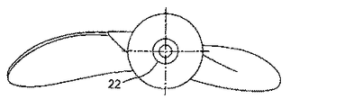
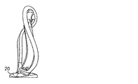
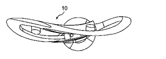
図1a〜図1e(従来技術)は、中央のプロペラ・ハブに公知の方法で取り付けられる構造の公知のプロペラ翼10の5枚の図である。翼10は、前縁12、後縁14、翼面16、先端部18、中央プロペラ・ハブに取り付けるためのフランジ20、及び翼10の重量を変更し、それによってプロペラのバランスを変更するために、材料を加え又は取り除くことができるバランス・ポケット22を含む。この説明では、プロペラという語は、船や航空機などのプロペラのような駆動モード、又はタービンや風車などのプロペラのような被駆動モードのプロペラにも使用する。
FIGS. 1 a-1 e (prior art) are five views of a known
図2a〜図2fは、本発明の第1の実施例によるプロペラ翼10の6枚の図である。この翼10は、図1に示す翼と同じ全体構成を有することも、又は、所望なら、別の構成を有することもできる。翼10は、概ね中実に鋳造され、フランジ20と一体化した周辺部24を含む。この周辺部の内部に、翼10が、支持構造体を形成する相互接続した支持翼桁及び間隙中空空間の内部LBM格子26から鋳造される。この支持構造体は、図2bにのみ示すが、他の図の周辺部24内の内部の空間も同様に充填することが理解されよう。図2bは、翼10がLMB格子26と連結し、それを被覆する中実の表皮層28を含むことを示す。好ましい実施例では、図2a〜図2fの翼10全体、及びその全ての構成部品は、単一の一体化した構成部品として鋳造されるが、それらはLBM格子26のために実質的に中空である。
2a to 2f are six views of the
翼10は以下のように製造する。翼10の所望の外部形状と大きさを有する翼鋳造鋳型を作成する。中実の鋳造翼を製造するための既存の鋳型が、所望の形状と大きさであれば使用できる。角柱形の鋳造コアを、コンパクトに隣接して接触させて積み上げることによってブロックを組み上げ、翼10内で所望のLBM格子のための所望の全体的大きさになるまで鋳造コア・ブロックを組み立てる。この時点で、鋳造コア・ブロックは一般に長方形のブロックの形態である。この鋳造コア・ブロックは、次いで公知の切断工具によって、所望の形状及び大きさのLBM格子をもたらす形状及び大きさにまで削ることができる。
The
図2a〜図2fに示す翼10を製造するには、翼鋳造鋳型内で、削った鋳造コア・ブロックの外面と翼鋳造鋳型の内面の間にクリアランスをもって鋳造コア・ブロックを位置決めすることができるように、鋳造コア・ブロックを削る。所望の状態で翼鋳造鋳型内に設置した後、削った鋳造コア・ブロックを、2つの構成部品間の所望の位置合わせが維持されるように、翼鋳造鋳型にピン留め又は固定する。2つの構成部品の間のクリアランスが事実上開いているので、そこは翼の鋳造時に材料で中実に充填され、それによって翼10の表皮層28、周辺部24及びフランジ20が生成される。しかし、鋳造材料は、鋳造コア・ブロック内の鋳造溝にしか入ることができず、鋳造コア材料が占めていた体積を充填することが妨げられる。
To produce the
翼鋳造物が十分に冷えた後で、未加工の翼鋳造物を、翼鋳造鋳型から取り外すことができる。次いで、鋳造コア・ブロックを、機械的工具、圧縮空気、振動などを使用して砕解し、砕解された材料を、表皮層28のバランス・ポケット22及び砂除去ポケット30を通して取り除く。この結果、LBM格子26が表皮層28、周辺部24及びフランジ20と一体で鋳造され、鋳造中に鋳造コア材料が以前に占めていた体積は、今は中空になる。
After the wing casting has cooled sufficiently, the raw wing casting can be removed from the wing casting mold. The cast core block is then crushed using mechanical tools, compressed air, vibration, etc., and the crushed material is removed through the
図3a〜図3fは、翼10の代替実施例の6枚の図を示す。この翼の実施例は図2a〜図2fに示す実施例と同様であるが、翼10の強度を増すために、一般的に中実である長手方向及び横方向補強翼桁32を含む。これらの補強翼桁32は、鋳造コア・ブロックを削り、それを翼鋳造鋳型内に配置するときに、この空間を開いたままにしておくことによって作り出される。これはただ1つの全体的鋳造コア・ブロックではなく、互いに所望の関係で配置し、固定した複数のより小さな鋳造コア・ブロックを使用して、その間に補強翼桁32になる鋳造材料が充填される自由空間を形成することによって最も効率的に行うことができる。所望の場合、この補強翼桁は、代替方法として互いに周辺部と、格子と、及び/又はフランジと連結することもできる。LBM格子26は、図3a〜図3fに示されていないが、図2bの如く、図示する空き領域に存在するはずであることは理解されよう。
FIGS. 3 a-3 f show six views of an alternative embodiment of the
図4a〜図4eは、図3a〜図3fの実施例と同様な代替実施例であるが、翼10は中央長手方向の補強翼桁32しか含まない。この実施例では、翼10は全体的な鋳造表皮部28を備えず、LBM格子26は周辺部24内に露出し、表皮部は、LBM格子の中空体積に比較的低重量の樹脂材料を加え、樹脂材料の露出した表面を所望の表面形状に鋳込むことによって形成される。そのような構成では、補強翼桁は表面樹脂をさらに強くする。代替方法として、表皮部は、露出した格子上に溶接、又は別の方法で取り付けることができる。
FIGS. 4 a-4 e are alternative embodiments similar to the embodiment of FIGS. 3 a-3 f, but the
図5は、本発明に従って製造された原型翼10を示す。いくつかの砂除去ポケット30が表皮部28に含まれている。内部LBM格子26は、図6〜図8に示す砂除去ポケット30の拡大詳細図でより容易に見ることができる。
FIG. 5 shows a
単一の一体鋳造プロペラも、上記の方法に従って製造することができる。この方法は、とりわけ、流体物質を移動させるために、又は流体物質によって移動されるように使用される任意の種類の空気力学的翼、例えば、航空機のプロペラ、タービン翼、送風機翼、風車翼、並びにより軽い構造体及び特定の外部形状を必要とする他の移動構造体を含む他の構成部品を製造するために使用することができる。 A single integral casting propeller can also be manufactured according to the method described above. This method can inter alia be any kind of aerodynamic wing used to move or be moved by fluid material, for example aircraft propellers, turbine blades, blower blades, windmill blades, As well as other components, including lighter structures and other moving structures that require specific external shapes.
したがって、本発明は、事実上中空であり、相当する中実の構成部品よりも相当軽く、しかしLBM格子26の内部補強に起因して所望の強度を保持する、鋳造プロペラ、プロペラ翼、又は他の構成部品を提供する。このようなプロペラは、プロペラの重量を支えなければならない翼取り付け部品、主軸及び主軸軸受に付加される応力を減少させる。プロペラのサイズは、翼取り付け構成部品、主軸、及び主軸軸受に過大な力を加えることなしに、より高い性能のためにサイズを大きくすることができる。あるいは、翼取り付け構成部品、主軸、及び主軸軸受のサイズ及び機械的特性は、プロペラの重量に起因するより低い力にしか曝されないので低減することができ、そのために推進システムの重量を全体として減少させることができる。
Accordingly, the present invention is a cast propeller, propeller blade, or other that is hollow in nature, substantially lighter than the corresponding solid component, but retains the desired strength due to the internal reinforcement of the
プロペラの重量がより軽くなるので、プロペラの重量を減少させるために、プロペラの形状及び構造に関して妥協を行う必要が少なくなる。これによって、キャビテーション、モード/振動特性及び他の特性に関して、重量を考慮することによって加えられる制限を余り受けずに、プロペラ翼の形状及び構成を設計し、最適な機能を実現することが可能となる。本発明は、重量がより軽いので、プロペラのすくい角及びスキューの設計許容範囲を広げ、そのために遠心運動により発生する機械的応力を減少させることができる。本発明のプロペラでは、材料の最大断面厚さが減少するので、材料の改良された微細組織、したがって、改良された機械的性質が得られる。 Since the weight of the propeller is lighter, there is less need to make a compromise regarding the shape and structure of the propeller to reduce the weight of the propeller. This makes it possible to design the shape and configuration of the propeller blades and achieve optimal functions without much of the limitations imposed by weight considerations regarding cavitation, mode / vibration characteristics and other characteristics. Become. Since the present invention is lighter in weight, it can increase the design tolerance of the rake angle and skew of the propeller, and thus reduce the mechanical stress caused by centrifugal motion. With the propeller of the present invention, the maximum cross-sectional thickness of the material is reduced, resulting in an improved microstructure of the material, and thus improved mechanical properties.
さらに本発明のプロペラは、中実のプロペラと比べ、モード/振動特性に関して無制限の調整の選択肢がある。本発明のプロペラは事実上中空なので、所望なら、この中空の内部はプロペラのモード/振動特性を変更するために様々な材料で充填することができる。例えば、プロペラの中空内部を軽量の樹脂で充填し、プロペラの重量をそれほど増加させることなく振動を減衰させることができる。樹脂は均一な密度を有することができ、あるいは異なる密度又は特性を有する樹脂又は材料を、特にプロペラの調整を行うために、中空領域内の異なる位置に置くこともできる。中空の領域は、所望の調整を実現するために、樹脂で完全に充填することも、又は特定の領域のみを部分的に充填することもできる。この調整は、LBM格子構造体内の材料の体積を、断面を横断して均一に又は不均一に変更することによっても実現することができる。プロペラの調整を行うために、補強翼桁及び砂除去/釣り合いポケットのサイズと位置は変更することができる。また内部格子により、性能を損なわず、付加又は除去しなければならない追加の重量を最小にせずに、極めて広い範囲にわたりプロペラのバランスをとることが可能になる。 Furthermore, the propellers of the present invention have unlimited adjustment options with respect to mode / vibration characteristics compared to solid propellers. Since the propeller of the present invention is hollow in nature, if desired, the hollow interior can be filled with a variety of materials to change the mode / vibration characteristics of the propeller. For example, the hollow inside of the propeller can be filled with a lightweight resin, and the vibration can be damped without increasing the weight of the propeller so much. The resin can have a uniform density, or resins or materials with different densities or properties can be placed at different locations within the hollow region, particularly for propeller adjustment. The hollow area can be completely filled with resin or only a specific area can be partially filled to achieve the desired adjustment. This adjustment can also be achieved by changing the volume of material in the LBM lattice structure uniformly or non-uniformly across the cross section. To adjust the propeller, the size and position of the reinforcing spar and sand removal / balance pocket can be changed. The internal grid also allows the propeller to be balanced over a very wide range without compromising performance and minimizing the additional weight that must be added or removed.
本発明の代替実施例では、鋳造コアの構成を、特定の領域で異なる格子翼桁密度を備え、及び/又は他の領域で格子翼桁密度を減少させるように変更することができる。例えば、プロペラの機械的応力がより高い領域では、格子翼桁密度を増加させてさらに強度を上げ、他方、より低い応力領域では、格子翼桁密度を減らして重量を減少させることができる。格子翼桁密度、配置及び/又は構成も、プロペラのモード/振動特性を変更するために、プロペラ内で均一に又は不均一に変更することができる。 In alternative embodiments of the present invention, the configuration of the cast core can be modified to provide different grid spars density in certain areas and / or reduce grid spars density in other areas. For example, in areas where the mechanical stress of the propeller is higher, the grid spar density can be increased to further increase strength, while in lower stress areas, the grid spar density can be reduced to reduce weight. Grating density, arrangement and / or configuration can also be changed uniformly or non-uniformly within the propeller to change the propeller mode / vibration characteristics.
本発明の一実施例では、プロペラ内の所望の格子翼桁の密度、構成及び配置を、均一であれ不均一であれ、有限要素分析などの選択された分析方法によって決定することができる。この情報は、CAD/CAMシステムに入力され、互いに組み立てたときに、所望の特定の翼桁密度、構成及び配置を有する格子構造体を生じる鋳造コア・ブロックを提供する、複数の個別の鋳造コアを作り出すための複数の型を作り出すために変換される。数値制御の切削機械をプログラミングし、それを使用して、鋳造に先立って鋳造コア・ブロックを所望の形状に削ることができる。 In one embodiment of the invention, the density, configuration and placement of the desired grid spar within the propeller can be determined by selected analytical methods, such as finite element analysis, whether uniform or non-uniform. This information is input into a CAD / CAM system and, when assembled together, provides a plurality of individual cast cores that provide a cast core block that produces a lattice structure with the desired specific spar density, configuration and arrangement. Converted to produce multiple molds for producing. A numerically controlled cutting machine can be programmed and used to cut the cast core block into the desired shape prior to casting.
本明細書で論じた様々な実施例の様々な態様を、異なる方式で組み合わせて新たな実施例を作り出し、本発明の範囲から逸脱することなく様々な改変を行うことができることが、意図されている。 It is intended that various aspects of the various embodiments discussed herein may be combined in different ways to create new embodiments, and that various modifications may be made without departing from the scope of the invention. Yes.
Claims (27)
前記格子支持構造体に取り付けられ、形状が所望の空気力学的形態である表皮部と備える、空気力学的翼。 An internal grid support structure having a plurality of interconnected support spar, the support spar between which is generally hollow;
An aerodynamic wing comprising a skin portion attached to the grid support structure and having a desired aerodynamic shape.
前記ハブに取り付けられた第1の複数の空気力学的翼を備える、プロペラであって、
前記第1の複数の空気力学的翼の各々が、
複数の相互接続された支持翼桁であって、それらの間の間隙空間が概ね中空である支持翼桁を有する内部格子支持構造体と、
前記格子支持構造体に取り付けられ、形状が所望の空気力学的形態である表皮部とを備える、プロペラ。 A hub for mounting on a driven / driven shaft;
A propeller comprising a first plurality of aerodynamic wings attached to the hub,
Each of the first plurality of aerodynamic wings is
An internal grid support structure having a plurality of interconnected support spar, the support spar between which is generally hollow;
A propeller attached to the lattice support structure and comprising a skin portion having a desired aerodynamic shape.
Applications Claiming Priority (2)
| Application Number | Priority Date | Filing Date | Title |
|---|---|---|---|
| US37571302P | 2002-04-29 | 2002-04-29 | |
| PCT/US2003/013359 WO2003093101A1 (en) | 2002-04-29 | 2003-04-09 | Propeller |
Publications (1)
| Publication Number | Publication Date |
|---|---|
| JP2006507965A true JP2006507965A (en) | 2006-03-09 |
Family
ID=29401300
Family Applications (1)
| Application Number | Title | Priority Date | Filing Date |
|---|---|---|---|
| JP2004501250A Pending JP2006507965A (en) | 2002-04-29 | 2003-04-09 | propeller |
Country Status (5)
| Country | Link |
|---|---|
| US (1) | US7144222B2 (en) |
| EP (1) | EP1499525A1 (en) |
| JP (1) | JP2006507965A (en) |
| AU (1) | AU2003228764A1 (en) |
| WO (1) | WO2003093101A1 (en) |
Families Citing this family (26)
| Publication number | Priority date | Publication date | Assignee | Title |
|---|---|---|---|---|
| US9153960B2 (en) | 2004-01-15 | 2015-10-06 | Comarco Wireless Technologies, Inc. | Power supply equipment utilizing interchangeable tips to provide power and a data signal to electronic devices |
| GB2450935B (en) * | 2007-07-13 | 2009-06-03 | Rolls Royce Plc | Component with internal damping |
| GB2450934B (en) * | 2007-07-13 | 2009-10-07 | Rolls Royce Plc | A Component with a damping filler |
| DE102007058811B4 (en) * | 2007-12-05 | 2009-12-24 | INOTEC GmbH Transport- und Fördersysteme | Boat propeller |
| GB0808840D0 (en) * | 2008-05-15 | 2008-06-18 | Rolls Royce Plc | A compound structure |
| EA017191B1 (en) * | 2008-06-09 | 2012-10-30 | Оао "Санкт-Петербургское Морское Бюро Машиностроения "Малахит" | Hollow blade of a ship propeller |
| US8328412B2 (en) * | 2008-06-20 | 2012-12-11 | Philadelphia Mixing Solutions, Ltd. | Combined axial-radial intake impeller with circular rake |
| GB2462102B (en) * | 2008-07-24 | 2010-06-16 | Rolls Royce Plc | An aerofoil sub-assembly, an aerofoil and a method of making an aerofoil |
| GB0822909D0 (en) | 2008-12-17 | 2009-01-21 | Rolls Royce Plc | Airfoil |
| GB0901235D0 (en) * | 2009-01-27 | 2009-03-11 | Rolls Royce Plc | An article with a filler |
| GB0901318D0 (en) * | 2009-01-28 | 2009-03-11 | Rolls Royce Plc | A method of joining plates of material to form a structure |
| US8213204B2 (en) | 2009-04-01 | 2012-07-03 | Comarco Wireless Technologies, Inc. | Modular power adapter |
| US8083489B2 (en) * | 2009-04-16 | 2011-12-27 | United Technologies Corporation | Hybrid structure fan blade |
| US8354760B2 (en) | 2009-10-28 | 2013-01-15 | Comarco Wireless Technologies, Inc. | Power supply equipment to simultaneously power multiple electronic device |
| GB201009216D0 (en) | 2010-06-02 | 2010-07-21 | Rolls Royce Plc | Rotationally balancing a rotating part |
| GB2485831B (en) | 2010-11-26 | 2012-11-21 | Rolls Royce Plc | A method of manufacturing a component |
| DE102016204393B3 (en) | 2016-03-16 | 2017-07-06 | Thyssenkrupp Ag | Natural frequency optimized propeller |
| US10228024B2 (en) * | 2017-01-10 | 2019-03-12 | General Electric Company | Reduced-weight bearing pins and methods of manufacturing such bearing pins |
| US10800542B2 (en) | 2017-07-14 | 2020-10-13 | Hamilton Sunstrand Corporation | Ram air turbine blades |
| US10633976B2 (en) * | 2017-07-25 | 2020-04-28 | Bell Helicopter Textron Inc. | Methods of customizing, manufacturing, and repairing a rotor blade using additive manufacturing processes |
| US11015461B2 (en) | 2017-12-21 | 2021-05-25 | General Electric Company | Composite hollow blade and a method of forming the composite hollow blade |
| US10975842B2 (en) | 2018-08-25 | 2021-04-13 | Samuel Messinger | Wind turbine propeller regulator to produce uninterrupted electricity and longer bearing life |
| US11215164B2 (en) | 2018-08-25 | 2022-01-04 | Samuel Messinger | Wind turbine propeller regulator to produce uninterrupted electricity and longer bearing life |
| US11572796B2 (en) | 2020-04-17 | 2023-02-07 | Raytheon Technologies Corporation | Multi-material vane for a gas turbine engine |
| US11795831B2 (en) | 2020-04-17 | 2023-10-24 | Rtx Corporation | Multi-material vane for a gas turbine engine |
| CN114309491B (en) * | 2021-12-29 | 2023-11-14 | 大连船用推进器有限公司 | Cavity structure and method convenient for observing baking state of large-sized propeller blade |
Family Cites Families (9)
| Publication number | Priority date | Publication date | Assignee | Title |
|---|---|---|---|---|
| GB792258A (en) * | 1955-06-06 | 1958-03-26 | Gen Motors Corp | Improved hollow propeller blade |
| GB2154286A (en) * | 1984-02-13 | 1985-09-04 | Gen Electric | Hollow laminated airfoil |
| GB2167500B (en) * | 1984-11-20 | 1988-05-18 | Rolls Royce | Rotor aerofoil blade containment |
| GB2168111B (en) * | 1984-12-08 | 1988-05-18 | Rolls Royce | Rotor aerofoil blade containment |
| US5269658A (en) * | 1990-12-24 | 1993-12-14 | United Technologies Corporation | Composite blade with partial length spar |
| US5634771A (en) * | 1995-09-25 | 1997-06-03 | General Electric Company | Partially-metallic blade for a gas turbine |
| WO1999055476A1 (en) | 1998-04-28 | 1999-11-04 | Jonathan Aerospace Materials Europe Ab | Method and device for casting three-dimensional structured objects |
| FR2784351B1 (en) * | 1998-10-12 | 2000-12-08 | Eurocopter France | DEVICE AND METHOD FOR REDUCING VIBRATIONS GENERATED ON THE STRUCTURE OF A ROTATING BLADE AIRCRAFT, IN PARTICULAR A HELICOPTER |
| US6033186A (en) * | 1999-04-16 | 2000-03-07 | General Electric Company | Frequency tuned hybrid blade |
-
2003
- 2003-04-09 JP JP2004501250A patent/JP2006507965A/en active Pending
- 2003-04-09 EP EP03726533A patent/EP1499525A1/en not_active Withdrawn
- 2003-04-09 WO PCT/US2003/013359 patent/WO2003093101A1/en not_active Application Discontinuation
- 2003-04-09 AU AU2003228764A patent/AU2003228764A1/en not_active Abandoned
- 2003-04-29 US US10/425,035 patent/US7144222B2/en not_active Expired - Lifetime
Also Published As
| Publication number | Publication date |
|---|---|
| EP1499525A1 (en) | 2005-01-26 |
| US20040005221A1 (en) | 2004-01-08 |
| WO2003093101A1 (en) | 2003-11-13 |
| US7144222B2 (en) | 2006-12-05 |
| AU2003228764A1 (en) | 2003-11-17 |
Similar Documents
| Publication | Publication Date | Title |
|---|---|---|
| JP2006507965A (en) | propeller | |
| US8936068B2 (en) | Method of casting a component having interior passageways | |
| JP5232174B2 (en) | Propeller blade retention | |
| CN102556334B (en) | Foam stiffened structure and manufacture method thereof | |
| DK178225B1 (en) | Rotor blade for a wind turbine and methods of manufacturing the same | |
| DK178162B9 (en) | Methods of manufacturing rotor blades for a wind turbine | |
| RU2706901C2 (en) | Blade of axial turbomachine, method of making blade of axial turbomachine and turbomachine | |
| EP2461923B1 (en) | Method for forming a cast article | |
| US7448433B2 (en) | Rapid prototype casting | |
| DE60315374T2 (en) | Hybrid process for producing a compressor wheel on titanium | |
| US20100221113A1 (en) | Internally-damped airfoil and method therefor | |
| EP2841702B1 (en) | Airfoil having tapered buttress | |
| EP1973716B1 (en) | Method for the milling machining of components | |
| EP1835129A2 (en) | Aerofoil for a gas turbine engine | |
| SE447635B (en) | WANT TO MANUFACTURE A SUSTAINABLE FORM | |
| WO2002077599A2 (en) | Rapid prototype wind tunnel model and method of making same | |
| EP3428395B1 (en) | Fan blade and fabrication method | |
| JP2011226480A (en) | Method for manufacturing wind turbine rotor blade and wind turbine rotor blade | |
| JP2001082388A (en) | Plastic molding hybrid blade part | |
| JP7320602B2 (en) | Wind turbine blade root attachment system and manufacturing method | |
| JP5228518B2 (en) | Wind turbine blade, molding die thereof and manufacturing method thereof | |
| US20190092458A1 (en) | Inertia Weight Assemblies for Rotorcraft | |
| WO2015015207A1 (en) | A tip cap for a fan blade | |
| GB2224784A (en) | Propeller blades | |
| EP0863073A2 (en) | Composite blade and forming method |
Legal Events
| Date | Code | Title | Description |
|---|---|---|---|
| A621 | Written request for application examination |
Free format text: JAPANESE INTERMEDIATE CODE: A621 Effective date: 20060331 |
|
| A131 | Notification of reasons for refusal |
Free format text: JAPANESE INTERMEDIATE CODE: A131 Effective date: 20080909 |
|
| A601 | Written request for extension of time |
Free format text: JAPANESE INTERMEDIATE CODE: A601 Effective date: 20081209 |
|
| A602 | Written permission of extension of time |
Free format text: JAPANESE INTERMEDIATE CODE: A602 Effective date: 20081216 |
|
| A601 | Written request for extension of time |
Free format text: JAPANESE INTERMEDIATE CODE: A601 Effective date: 20090109 |
|
| A602 | Written permission of extension of time |
Free format text: JAPANESE INTERMEDIATE CODE: A602 Effective date: 20090119 |
|
| A601 | Written request for extension of time |
Free format text: JAPANESE INTERMEDIATE CODE: A601 Effective date: 20090209 |
|
| A602 | Written permission of extension of time |
Free format text: JAPANESE INTERMEDIATE CODE: A602 Effective date: 20090217 |
|
| A521 | Written amendment |
Free format text: JAPANESE INTERMEDIATE CODE: A523 Effective date: 20090309 |
|
| A02 | Decision of refusal |
Free format text: JAPANESE INTERMEDIATE CODE: A02 Effective date: 20090908 |