JP2006506268A - Windshield wiper for automobile having arm and articulation connector - Google Patents
Windshield wiper for automobile having arm and articulation connector Download PDFInfo
- Publication number
- JP2006506268A JP2006506268A JP2004552656A JP2004552656A JP2006506268A JP 2006506268 A JP2006506268 A JP 2006506268A JP 2004552656 A JP2004552656 A JP 2004552656A JP 2004552656 A JP2004552656 A JP 2004552656A JP 2006506268 A JP2006506268 A JP 2006506268A
- Authority
- JP
- Japan
- Prior art keywords
- arm
- connector
- support element
- wiper
- pivot
- Prior art date
- Legal status (The legal status is an assumption and is not a legal conclusion. Google has not performed a legal analysis and makes no representation as to the accuracy of the status listed.)
- Pending
Links
Images


Classifications
-
- B—PERFORMING OPERATIONS; TRANSPORTING
- B60—VEHICLES IN GENERAL
- B60S—SERVICING, CLEANING, REPAIRING, SUPPORTING, LIFTING, OR MANOEUVRING OF VEHICLES, NOT OTHERWISE PROVIDED FOR
- B60S1/00—Cleaning of vehicles
- B60S1/02—Cleaning windscreens, windows or optical devices
- B60S1/04—Wipers or the like, e.g. scrapers
- B60S1/32—Wipers or the like, e.g. scrapers characterised by constructional features of wiper blade arms or blades
- B60S1/40—Connections between blades and arms
- B60S1/4038—Connections between blades and arms for arms provided with a channel-shaped end
-
- B—PERFORMING OPERATIONS; TRANSPORTING
- B60—VEHICLES IN GENERAL
- B60S—SERVICING, CLEANING, REPAIRING, SUPPORTING, LIFTING, OR MANOEUVRING OF VEHICLES, NOT OTHERWISE PROVIDED FOR
- B60S1/00—Cleaning of vehicles
- B60S1/02—Cleaning windscreens, windows or optical devices
- B60S1/04—Wipers or the like, e.g. scrapers
- B60S1/32—Wipers or the like, e.g. scrapers characterised by constructional features of wiper blade arms or blades
- B60S1/38—Wiper blades
- B60S1/3848—Flat-type wiper blade, i.e. without harness
- B60S1/3849—Connectors therefor; Connection to wiper arm; Attached to blade
-
- B—PERFORMING OPERATIONS; TRANSPORTING
- B60—VEHICLES IN GENERAL
- B60S—SERVICING, CLEANING, REPAIRING, SUPPORTING, LIFTING, OR MANOEUVRING OF VEHICLES, NOT OTHERWISE PROVIDED FOR
- B60S1/00—Cleaning of vehicles
- B60S1/02—Cleaning windscreens, windows or optical devices
- B60S1/04—Wipers or the like, e.g. scrapers
- B60S1/32—Wipers or the like, e.g. scrapers characterised by constructional features of wiper blade arms or blades
- B60S1/40—Connections between blades and arms
- B60S1/4038—Connections between blades and arms for arms provided with a channel-shaped end
- B60S1/4041—Connections between blades and arms for arms provided with a channel-shaped end the channel-shaped end comprising a pivot pin mounted between the side walls
-
- B—PERFORMING OPERATIONS; TRANSPORTING
- B60—VEHICLES IN GENERAL
- B60S—SERVICING, CLEANING, REPAIRING, SUPPORTING, LIFTING, OR MANOEUVRING OF VEHICLES, NOT OTHERWISE PROVIDED FOR
- B60S1/00—Cleaning of vehicles
- B60S1/02—Cleaning windscreens, windows or optical devices
- B60S1/04—Wipers or the like, e.g. scrapers
- B60S1/32—Wipers or the like, e.g. scrapers characterised by constructional features of wiper blade arms or blades
- B60S1/38—Wiper blades
- B60S1/3848—Flat-type wiper blade, i.e. without harness
- B60S1/3849—Connectors therefor; Connection to wiper arm; Attached to blade
- B60S1/3865—Connectors having an integral pivot pin for connection with the wiper arm
- B60S1/3868—Connectors having an integral pivot pin for connection with the wiper arm pin formed on the exterior of side walls
Abstract
Description
本発明は、駆動アームの端部に関節接続をするように取り付けられた、コンパクトな垂直ワイパーブレードを含む自動車の窓ガラス用ワイパーに関するものである。 The present invention relates to a windshield wiper for a motor vehicle that includes a compact vertical wiper blade that is articulated to the end of a drive arm.
より詳細には、本発明は、コネクタにより、横方向水平軸線を中心として、ワイパーアームの長手方向前端部において、関節接続されるように取り付けられたワイパーブレードを備える自動車用ワイパーであって、
前記コネクタは、ほぼ水平の本体を備え、この本体の底面は、前記ブレードのワイパーゴムを支持する構造要素に前記ブレードを固定するためのフックを支持しており、
前記コネクタ本体の頂面は、前記横方向関節接続軸線を中心とする、前記アームの端部との関節接続手段を支持しており、
前記アームの端部は、ウェブを備え、このウェブは、前記コネクタの上方において、ほぼ水平に延び、前記横方向関節接続軸線を中心とする前記コネクタの関節接続手段を支持しており、
前記アームの端部との前記コネクタの関節接続手段は、前記横方向関節接続軸線と同軸状の横方向軸線を有する少なくとも1つのピボットを備え、前記ピボットは、前記アームの端部に属すか、または前記コネクタに属す関連する第1支持要素の側面から横方向に延び、かつ、コネクタに属すか、または前記アームの端部にそれぞれ属す関連する第2支持要素に設けられた相補的ハウジング内に嵌合できるようになっており、
前記第1支持要素または前記第2支持要素は、前記関連するハウジング上の前記ピボットの挿入を可能にし、かつ前記ハウジング内に、前記ピボットの自動ラジアルロッキングを生じさせる弾性変形可能な要素を備え、
前記第1支持要素および第2支持要素は、プラスチック材料を成形することによって、前記アームまたは前記コネクタとそれぞれ一体に製造されている自動車用ワイパーに関する。
More particularly, the present invention is an automotive wiper comprising a wiper blade mounted to be articulated at a longitudinally forward end of a wiper arm about a horizontal horizontal axis by a connector,
The connector includes a substantially horizontal main body, and a bottom surface of the main body supports a hook for fixing the blade to a structural element that supports a wiper rubber of the blade;
The top surface of the connector body supports joint connection means with the end of the arm centered on the lateral joint connection axis.
The end of the arm includes a web, the web extends substantially horizontally above the connector and supports the articulation means of the connector about the lateral articulation axis;
The articulation means of the connector with the end of the arm comprises at least one pivot having a transverse axis coaxial with the transverse articulation axis, the pivot belonging to the end of the arm; Or in a complementary housing provided laterally extending from the side of the associated first support element belonging to the connector and provided to the associated second support element belonging to the connector or respectively belonging to the end of the arm Can be mated,
The first support element or the second support element comprises an elastically deformable element that allows insertion of the pivot on the associated housing and causes automatic radial locking of the pivot within the housing;
The first support element and the second support element relate to an automobile wiper that is manufactured integrally with the arm or the connector by molding a plastic material.
高さの低いワイパーブレードを製造するための設計においては、ワイピングゴムまたはストリップを支持するワイパーブレードの関節接続構造体は省略され、ワイパーブレードを正しく構成するように、可撓性ワイパーストリップに、構造上の補強要素が連係されている。 In the design for manufacturing a low-profile wiper blade, the wiper blade articulation structure supporting the wiping rubber or strip is omitted, and the flexible wiper strip is structured to ensure proper construction of the wiper blade. The upper reinforcing elements are linked.
ワイパーブレードは、ブレードを駆動するアームを備える公知の駆動機構により、ワイピングするべき窓ガラス上で、交互にスイープするように駆動される。ワイピングするべき窓ガラスは、複雑な形状となっているので、ブレードは、関節接続コネクタにより、駆動アームに対し、横方向軸線を中心として関節接続するように取り付けられる。 The wiper blade is driven so as to sweep alternately on a window glass to be wiped by a known driving mechanism including an arm for driving the blade. Since the window glass to be wiped has a complicated shape, the blade is attached to the drive arm by the joint connector so as to be articulated around the lateral axis.
公知の例においては、コネクタは、構造上の要素によりブレードに固定され、横方向関節接続軸線を中心として、アームに対し関節運動するように取り付けられている。 In the known example, the connector is fixed to the blade by structural elements and is mounted to articulate with respect to the arm about the transverse articulation axis.
国際特許出願第WO-A-02.34592号には、駆動アームの端部に、高さの低いブレードを接続したコネクタが記載されている。このコネクタは、ブレードを構造要素に固定するための手段と、ワイパーアームに関節接続する手段と、関節接続軸線を中心として、ワイパーアームに対しコネクタをガイドするための手段とを備えている。 International Patent Application No. WO-A-02.34592 describes a connector in which a blade having a low height is connected to the end of a drive arm. The connector comprises means for fixing the blade to the structural element, means for articulating the wiper arm, and means for guiding the connector relative to the wiper arm about the articulation axis.
コネクタが関節接続されるアームの端部は、弾性変形可能な要素を備え、この要素によって、アームの端部に、コネクタを比較的容易に組み立てできるようになっている。この組み立ては、スナップオン組み立てとも呼ばれている。 The end of the arm to which the connector is articulated comprises an elastically deformable element that allows the connector to be assembled relatively easily at the end of the arm. This assembly is also called snap-on assembly.
ワイパーブレードに固定する機能、およびアームの端部に関節接続する機能を満たすために、コネクタの種々の部品は、曲げられており、その製造は相当に複雑となっており、その製造コストは高められている。 In order to satisfy the function of fixing to the wiper blade and the function of articulating at the end of the arm, the various parts of the connector are bent and their manufacture is considerably complicated, increasing their manufacturing costs. It has been.
ドイツ国特許出願第DE-A1-100.39.291号には、別の公知のワイパーが示されている。このワイパーのアームは、アームに対して、コネクタを長手方向に位置決めするための手段を備え、この手段は、コネクタに対してアームを関節接続させる機能をも有する。しかし、同一構造体により、位置決めと関節接続という2つの機能を果たせるため、これら各手段の構造を、個々に最適にすることが不可能となっている。 Another known wiper is shown in German patent application DE-A1-100.39.291. The arm of the wiper includes means for positioning the connector in the longitudinal direction with respect to the arm, and this means also has a function of articulating the arm with respect to the connector. However, since the two functions of positioning and joint connection can be performed by the same structure, it is impossible to optimize the structure of each means individually.
本発明の目的は、コストを削減し、アームに対するコネクタの位置決め、および、その関節接続の双方を最適にするようにした製造手段により、コネクタを形成したアームを提案することにある。 It is an object of the present invention to propose an arm in which a connector is formed by a manufacturing means that reduces costs and optimizes both the positioning of the connector relative to the arm and its joint connection.
この目的のために、本発明は、上記タイプのワイパーにおいて、アームの端部に、関節接続手段と異なるコネクタを長手方向に位置決めする手段を設けてあることを特徴とするワイパーを提案するものである。 For this purpose, the present invention proposes a wiper characterized in that, in the wiper of the type described above, means for positioning a connector different from the joint connection means in the longitudinal direction is provided at the end of the arm. is there.
本発明のその他の特徴は、次のとおりである。 Other features of the present invention are as follows.
前記位置決め手段は、アームの長手方向に対して、実質的に横方向に延びている。 The positioning means extends substantially laterally with respect to the longitudinal direction of the arm.
前記位置決め手段は、2つの横方向垂直リブを備え、これらのリブは、前記アーム)の端部の2つの側面部を接続しており、かつ、前記アームのウェブに対して長手方向に分散しており、よって、コネクタがアームの端部の側面部の間の所定位置に取り付けられているとき、コネクタは、横方向リブの間で、長手方向に延びている。 The positioning means comprises two lateral vertical ribs, which connect the two side surfaces at the end of the arm) and are distributed longitudinally with respect to the web of the arm. Thus, the connector extends longitudinally between the lateral ribs when the connector is mounted in place between the sides of the end of the arm.
前記コネクタは、傾斜部の形態をした部分を備え、前記ピボットをハウジング内に挿入する前に、前記傾斜部は、リブの底部エッジと協働し、よって、コネクタを長手方向に位置決めできるようになっている。 The connector comprises a portion in the form of a ramp, so that before the pivot is inserted into the housing, the ramp cooperates with the bottom edge of the rib so that the connector can be positioned longitudinally. It has become.
前記コネクタおよびアームは、横方向関節接続軸線を中心とする、アームに対するブレードおよびコネクタの枢動の大きさを制限する手段を備えている。 The connector and arm include means for limiting the amount of pivoting of the blade and connector relative to the arm about the transverse articulation axis.
前記コネクタは、少なくとも1つのリブを備え、このリブの頂部表面は、アームに対するブレードの極端な回転角方向位置にあるときに、アームの端部のウェブの底面に当接する。 The connector comprises at least one rib whose top surface abuts the bottom surface of the web at the end of the arm when in the extreme rotational angular position of the blade relative to the arm.
前記アームに対し、ブレードが極端な回転角方向位置にあるときに、ゴム製の頂部面が、前記リブの底部エッジに当接するように、アームの少なくとも1つの横方向リブは、垂直下方に延びている。 At least one lateral rib of the arm extends vertically downward so that when the blade is in an extreme rotational angular position relative to the arm, the rubber top surface abuts the bottom edge of the rib. ing.
前記第2支持要素は、弾性クランプを備え、このクランプのブランチに対向する内側面の各々は、ハウジングの境界を部分的に定める凹部を備え、前記クランプのブランチは、全体として、横方向軸線を中心として関節接続され、よって、前記ピボットをハウジング内に挿入できるように分離している。 The second support element comprises an elastic clamp, each inner surface facing the branch of the clamp comprising a recess partly delimiting the housing, the branch of the clamp as a whole having a transverse axis. It is articulated as a center and is thus separated so that the pivot can be inserted into the housing.
前記ピボットを関連するハウジング内に垂直に導入できるように、前記弾性クランプのブランチは、ほぼ垂直に延びている。 The branches of the elastic clamps extend substantially vertically so that the pivot can be introduced vertically into the associated housing.
前記支持要素は、長手方向垂直側面部から成り、この側面部は、ハウジングを構成する円形断面を有する横方向オリフィスを備えている。 The support element comprises a longitudinal vertical side, which is provided with a transverse orifice having a circular cross-section constituting a housing.
前記側面部は、傾斜部の形態をした部分を有し、この傾斜部は、前記側面部の長手方向自由エッジから横方向オリフィスまで延び、前記ピボットをハウジング内に挿入すると、ピボットは、オリフィスに当接して、弾性変形可能な要素を変形させるようになっている。 The side portion has a portion in the form of an inclined portion that extends from a longitudinal free edge of the side portion to a lateral orifice, and when the pivot is inserted into the housing, the pivot moves into the orifice. Abuttingly deforms the elastically deformable element.
前記側面部は、弾性的に変形可能である。 The side portion is elastically deformable.
前記ピボットの自由端は、面取りされており、前記ピボットをハウジング内に挿入したときに、傾斜部の形態をした側面部の部分と協働しうるようになっている。 The free end of the pivot is chamfered so that it can cooperate with a portion of the side surface in the form of a ramp when the pivot is inserted into the housing.
前記第2支持要素は、長手方向垂直側面を備え、前記第1支持要素に属す対向する長手方向垂直面は、前記側面と協働し、前記アームの前端部に対して、コネクタを回転自在にガイドできるようになっている。 The second support element includes a longitudinal vertical side surface, and the opposing longitudinal vertical surface belonging to the first support element cooperates with the side surface to rotate the connector relative to the front end of the arm. You can guide.
前記第2支持要素は、長手方向垂直側面を備え、前記リブに属する対向する長手方向垂直ガイド面は、前記側面と協働し、前記アームの前端部に対して、コネクタを回転自在にガイドできるようになっている。 The second support element has a longitudinal vertical side surface, and opposing longitudinal vertical guide surfaces belonging to the rib cooperate with the side surface to rotatably guide the connector with respect to the front end portion of the arm. It is like that.
前記第2支持要素は、少なくとも1つの長手方向垂直側面部を備え、前記関連する第1支持要素と対向する前記側面部の側面は、前記クランプに対して、横方向に突出し、回転自在にガイドするための表面を形成している。 The second support element includes at least one longitudinal vertical side surface, and the side surface of the side surface facing the associated first support element protrudes laterally with respect to the clamp and is rotatably guided. A surface for forming is formed.
前記コネクタは、クランプの片側において、長手方向に分散した2つの長手方向垂直側面部を備え、前記ガイド表面を形成する側面部の側面は、コネクタの本体の各側で、長手方向に延びている。 The connector includes two longitudinal vertical side portions distributed in the longitudinal direction on one side of the clamp, and the side surfaces of the side portions forming the guide surface extend in the longitudinal direction on each side of the main body of the connector. .
前記第1支持要素およびリブは、第2支持要素の各側で、横方向に分散している。 The first support elements and ribs are laterally distributed on each side of the second support element.
前記第1支持要素は、コネクタの要素であり、第2支持要素は、前記アームの端部の一部である。 The first support element is an element of a connector, and the second support element is a part of an end of the arm.
前記リブは、コネクタの一部である。 The rib is a part of the connector.
前記第1支持要素は、アームの端部の要素であり、前記第2支持要素は、コネクタの一部である。 The first support element is an element at an end of an arm, and the second support element is a part of a connector.
前記リブは、アームの端部の一部である。 The rib is a part of the end of the arm.
前記コネクタおよび前記アームの端部の各々は、同じ長手方向垂直中間平面に対して対称的であり、よってコネクタは、2つの第1支持要素、または2つの第2支持要素を備え、前記アームの端部は、2つの第2支持要素、または2つの第1支持要素をそれぞれ含んでいる。 Each of the connector and the end of the arm is symmetrical with respect to the same longitudinal vertical intermediate plane, so the connector comprises two first support elements, or two second support elements, The end portion includes two second support elements or two first support elements, respectively.
前記リブは、前記2つの第2支持要素の間に、横方向に配置されている。 The rib is arranged laterally between the two second support elements.
添付図面を参照し、次の詳細な説明を読めば、本発明の上記以外の特徴、および利点が明らかとなると思う。 Other features and advantages of the present invention will become apparent from the following detailed description when read in conjunction with the accompanying drawings.
本発明の説明において、図に示された基準V、L、Tは、それぞれ、垂直方向、長手方向および横方向を、非限定的に定めるものとする。 In the description of the present invention, the references V, L and T shown in the figures shall define the vertical direction, the longitudinal direction and the lateral direction, respectively, without limitation.
後方から前方への向きは、図1における右から左への方向とする。 The direction from the rear to the front is the direction from right to left in FIG.
「底部」なる用語は、概ねワイピングするべき窓ガラスの方向の部分を指すものとする。 The term “bottom” shall refer generally to the portion of the glazing direction to be wiped.
「頂部」なる用語は、ワイピングすべき窓ガラスとほぼ反対方向の部分を意味するものとする。 The term “top” is intended to mean the portion in the direction generally opposite to the glazing to be wiped.
次の説明では、同一、同様、または類似の要素には、同じ符号を付してある。 In the following description, identical, similar, or similar elements are given the same reference numerals.
図1は、コネクタ24により、ワイパーアーム22の長手方向の前方自由端部22aに対して、横方向の軸線Aを中心として回転するように取り付けられるようになっているワイパーアーム20を示す。
FIG. 1 shows a
ワイパーブレード20は、長手方向に延びるスクレイパー26を備え、スクレイパー26は、底部でワイピングすべき窓ガラスを摺擦するようになっているブレード28と、頂部にある固定ヒール30と、ゴム28をヒール30に接続するヒンジを形成するストリップ32とからなっている。
The
ワイパーブレード20は、ヒール30の側方エッジに形成された相補的な溝内に嵌合された補強用せきつい部材34を備えている。
The
これらせきつい部材34は、ワイパーブレード20を補強し、ワイプすべき窓ガラスに対して、スクレイパー26の支持力を、その全長にわたって分散させるようになっている。
These damming
特に図3aから詳細に理解できるように、コネクタ24は、全体として平面状のプレートから成る本体38を備え、このプレートは、スクレイパー26のヒール30の上方で水平に延びており、この本体の底面38iは、コネクタ24をワイパーブレード20に固定する手段を支持している。
As can be seen in particular from FIG. 3a in particular, the
この固定手段は、2つのフック40から成り、フックは、本体38の各側方エッジに沿って垂直下方に延び、フックの底部自由端は、コネクタ24の内部に向かって水平にカーブし、各フック40には、せきつい部材34の長手方向外側エッジを嵌合して、ブレード20に対して、コネクタ24を垂直かつ横方向に位置決めできるようになっている。
This securing means consists of two
ブレード20に対するコネクタ24の長手方向の位置決めは、位置決め突起(図示せず)によって行われる。この突起は、フック40の内側面から横方向に延び、関連するせきつい部材34内の相補的ノッチに嵌合されるようになっている。
Positioning of the
コネクタ24の本体38の頂部面38sには、横方向関節接続軸線Aを中心として関節接続する手段46aが支持され、この関節接続手段は、アーム22の長手方向前端部22aに対する相補的関節接続手段46bと協働しうる。
The top surface 38s of the
図2から判るように、アーム22は、細長くて、U字形の垂直断面を有し、水平頂部ウェブ48と2つの側面部50とを備え、側面部50は、頂部ウェブ48の側方エッジから、下方に垂直に延びている。
As can be seen from FIG. 2, the
アーム22の長手方向の後端部22bは、垂直軸線を中心として回転駆動するためのヘッド(図示せず)を受けるように、それと形状が合致している。
The rear end portion 22b in the longitudinal direction of the
図1からより詳細に理解できるように、アーム22の前端部22aは、アームがコネクタ24に接続されると、コネクタ24全体が、アーム22の前端部22aによってカバーされるように、形状が合致している。
As can be seen in more detail from FIG. 1, the
この目的のために、コネクタ24が、アーム24の前端部22a上の取り付け位置にあるとき、前端部22aのウェブ48は、コネクタ24のまわりに延び、コネクタ24の各側において、コネクタから所定の距離に、アーム22の前端部22aの側面部50が延びている。更に頂部ウェブ48は、コネクタ24の前方に延びるほぼ垂直の横方向側面部52として前方に延びている。
For this purpose, when the
アーム22は、所定の数の補強リブ54を有し、これらのリブは、側面部50を一体に接続すると共に、これら側面部2も接続し、これらのリブは、アーム22に対する十分な強度を発揮するように、アーム22の中心部分22c内に分散されている。
The
最後に、アーム22の前端部22aの頂部ウェブ48は、その底面48において、コネクタ24の関節接続手段46aと協働する関節接続手段46bを支持している。
Finally, the
図3a〜図6cに示すように、アーム22の前端部22aを有するコネクタ24の関節接続手段46a、46bは、少なくとも1つの円筒形ピボット56を備え、このピボット56は、円形断面および横方向関節接続軸線Aと合流する横方向軸線を有する。
As shown in FIGS. 3a-6c, the articulation means 46a, 46b of the
ピボット56は、第1支持要素58の側方面58aから横方向に延びるよう、関連する第1の支持要素58により、横方向端部56aの少なくとも1つに支持されている。
The
アーム22の前端部22aとコネクタ24とを関節接続する手段46a、46bは、少なくとも1つの第2支持要素60を備え、この支持要素では、横方向関節接続軸線Aを中心として、アーム22の前端部22aに対し、コネクタ24を回転自在にガイドするよう、ピボット56の相補的ハウジング62が形成されている。
The
第1支持要素58は、この第1支持要素58が、コネクタ24に属すか、またはアーム22の前端部22aに属すように配置されている。第2支持要素60は、この第2支持要素60が、アーム22の前端部22aに属すか、またはコネクタ24に属すように配置されている。
The
最後に、第1支持要素58または第2支持要素60は、ピボット56を関連するハウジング62内に挿入でき、かつピボット56を、ハウジング62内で自動的にラジアルロッキングさせるように、弾性的に変形できる要素を備えている。
Finally, the
これら弾性変形可能な要素により、ピボット56を、関連するハウジング62内に弾性取り付けすることが可能であり、アーム22とコネクタ24とを、容易に組み立てできる。この組み立ては、スナップオン組み立てとも称される。
These elastically deformable elements allow the
第1支持要素58と第2支持要素60とは、プラスチック材料を成形することにより、アーム22またはコネクタ24とそれぞれ一体に製造されている。
The
プラスチック成形によると、低いコストおよび少ない製造条件で、複雑な形状の部材を製造することができる。 According to plastic molding, a member having a complicated shape can be manufactured at low cost and with low manufacturing conditions.
コネクタ24とアーム22は、単一要素から成っているので、ワイパーの組み立てが簡単となり、コネクタ24とアーム22との取り付けは、弾性スナップオン操作によって行うことができる。
Since the
本発明の一実施例によれば、コネクタ24とアーム22の前端部22aは、同じ垂直長手方向中心平面に対して対称的でり、これら各部品は、2つの第1支持要素58または第2支持要素60をそれぞれ含んでいる。
According to one embodiment of the present invention, the
次の説明では、単一第1支持要素58、および単一第2支持要素60を参照するが、この説明は、他の第1支持要素58、および他の第2支持要素60にも適用できることが理解できると思う。
In the following description, reference is made to a single
図3a〜図3cに示す本発明の一実施例によれば、第2支持要素60は、コネクタ24の要素であり、第1支持要素58は、アーム22の前端部要素22aである。
According to one embodiment of the invention shown in FIGS. 3 a-3 c, the
第2支持要素60は、弾性クランプ64を有し、このクランプのブランチ66は、本体38の側方エッジから垂直上方に延び、かつ、アーム22に対するブレード20上の横方向関節接続軸線Aの下方に位置する横方向軸線を中心として、関節接続されている。
The
2つのブランチ66の対向する内側面は、関連するブランチ66のベースの近くに、部分的にハウジング62の境界を定める凹状部分68と、関連するブランチ66の頂部自由端にある横方向に平行な傾斜部70の形状をした部分とを有し、ピボット56がハウジング62に挿入され、関連するブランチ66を分離させるときに、ピボット56が傾斜部70に当接するようになっている。
Opposite inner surfaces of the two
従って、ワイパーアーム22にコネクタ24を取り付けると、ピボット56は、垂直下方運動により、関連するハウジング62内に挿入される。アーム22の前端部22aが、その底部部分において開口するほぼシェル状となっていると仮定した場合、コネクタ24とアーム22とを組み立てる人にとって、このタイプの運動は自然なものとなる。
Thus, when the
この実施例によれば、アーム22の前端部22aは、単一ピボット56を有し、このピボットは、アーム22の側面部50の間で横方向に延び、ピボット56の各端部56aは、2つの支持要素60のうちの1つに関連し、弾性クランプ64のブランチ66の間に嵌合される。
According to this embodiment, the
この実施例によれば、ピボット56は、2つの長手方向フランジにより、アーム22に接続されており、フランジは、ウェブ48の底面48iから垂直下方に延び、各フランジは、第1支持要素58を形成し、フランジの対向する垂直長手方向面58aは、ピボット56を支持している。
According to this embodiment, the
アーム22の側面部50の間に、横方向の2つの長手方向フランジが配置され、コネクタ24がアーム22に取り付けられた状態にあるときに、フランジは、コネクタ24の各側面に位置するようになっている。
Two lateral longitudinal flanges are disposed between the
フランジの間の剛性を増すために、フランジの長手方向端部は、リブ82により、アーム22の側面部50に接続されている。
In order to increase the rigidity between the flanges, the longitudinal ends of the flanges are connected to the
図4a〜図4bに示す別の実施例によれば、第1支持要素58は、アーム22の前端部22aの長手方向垂直中間平面に横方向に接近するように配置されているので、2つの第2支持要素60の間に、アーム22の前端部22aの2つのフランジが横方向に配置され、第1支持要素58の外側側方面58aから、アーム22の外側に向かって、横方向に関連するピボット56が延びている。
According to another embodiment shown in FIGS. 4 a-4 b, the
図5a〜図5cに示す変形実施例によれば、第2支持要素60は、長手方向側面部から成っている。この側面部は、本体38の頂部面38sから垂直上方に延びており、ハウジング62の境界を定める横方向オリフィス72を備えている。
According to the variant shown in FIGS. 5a to 5c, the
ハウジング62内へのピボット56の挿入は、コネクタ24に対して、アーム22を垂直下方に移動させることによっても行うことができる。このために、横方向オリフィス72の横方向円筒形壁は、ピボット56がハウジング62に挿入されるのを防止している。
The
その理由は、第2支持要素60が弾性的に変形可能であり、第2支持要素60の垂直長手方向平面に対して傾斜した傾斜部74の形態をした部分を有するからであり、この部分は、第2支持要素60の頂部長手方向エッジ60sから、横方向オリフィス72の円筒形の壁まで垂直に延びている。
The reason is that the
ピボット56をハウジング62に挿入すると、ピボット56は、傾斜部74の形状をした部分に当接し、主に傾斜部74の形状をした部分から成る第2支持要素60を変形させ、傾斜部74は、ピボット56を通過できるように横方向に後退する。
When the
更に傾斜部74の形状をした部分に当接するピボット56の端部56aは、傾斜部74の形状をした部分に相補的となるように面取りされている。この面取り部分は、第2支持要素60を変形させるように、傾斜部74の形状をした部分と協働する。
Further, the
この変形実施例によれば、横方向オリフィス72は、コネクタ24に対する横方向端部の一方、すなわち、横方向外側端部で開口する盲孔となっている。
According to this variant embodiment, the
ピボット56は、横方向オリフィス72の開端部と横方向反対に配置された、すなわち、コネクタ24の横方向外側に配置された第1支持要素58によって支持されており、横方向オリフィス72の開端部の方、すなわちアーム22の内側を向く第1支持要素58の面58aから、横方向にピボット56が延びている。
The
図6a〜図6cは、第1支持要素58、従ってピボット56が、コネクタ24の1つの要素であり、第2支持要素60が、アーム22の前端部22aの要素である別の実施例を示している。
FIGS. 6 a-6 c show another embodiment in which the
第1支持要素58および第2支持要素60の構造だけでなく、ピボット56の構造も、前の実施例の構造と類似している。すなわち、第2支持要素60は、ハウジング62の境界を定める横方向オリフィス72を備える長手方向垂直側面部から成り、第1支持要素58は、側方面58aの1つに、ピボット56を支持する垂直フランジから成っている。
Not only the structure of the
当然ながら、第2支持要素60は、アーム22の前端部22aのウェブ48から、垂直下方に延びる弾性クランプ64を有することができる。
Of course, the
ピボット56の形状と相補的な、すなわち、断面が円筒形をした円筒体であるハウジング62のチャンバにより、アーム22の前端部22aに対し、コネクタ24の横方向関節接続軸線Aを中心に、回転自在にガイドできるようになっている。しかし、この形状は、アーム22に対するコネクタ24の横方向の移動をロックすることを保証するものではない。
The
従って、コネクタ24とアーム22との間に、横方向の遊びが生じることがあり、ワイパーの作動中に、不快なノイズが生じたり、ワイパーの種々の要素が破壊されることがあり得る。
Accordingly, lateral play may occur between the
その理由は、図4a〜図4cおよび図6a〜図6cに示すように、第1支持要素58と第2支持要素60の各々はガイド面を有し、これらの面は、第1および第2支持要素58、60とそれぞれ対向する長手方向の垂直側面となり、これらの面は、アーム22の前端部22aに対するコネクタ24を回転自在にガイドするように協働するからである。
The reason is that, as shown in FIGS. 4a to 4c and 6a to 6c, each of the
図5a〜図5cに示す本発明の変形例によれば、第2支持要素60の長手方向垂直面は、ガイドリブ78に対向する長手方向垂直面78aと協働する。
According to the variant of the invention shown in FIGS. 5 a to 5 c, the longitudinal vertical surface of the
このガイドリブ78は、第1支持要素58がアーム22と一体的に製造されるときには、第1支持要素58と一体的に、すなわち、アーム22と一体的に製造される。また、第1支持要素58がコネクタ24と一体的に製造されるときには、コネクタ24と一体的に製造される。
The
更に、ガイドリブ78は第2支持要素60の各側に、ガイド78および第1支持要素58が分散するように、アーム22またはコネクタ24に横方向にそれぞれ位置する。
Furthermore, the
従って、図5a〜図5cから判るように、第1支持要素58がコネクタ24に対し、第2支持要素60の外側面に対向して位置するとき、ガイドリブ78は、第2支持要素60の内側面に対向して位置し、この逆に、第2支持要素の内側面に第1支持要素58が対向して位置するときには、第2支持要素の外側面に、ガイドリブ78が対向して位置する。
Accordingly, as can be seen from FIGS. 5 a to 5 c, when the
更に、ガイドリブ78が第2支持要素60の内側面に対向して位置し、アーム22の前端部22aとコネクタ24とが、平面に対して対称的であるとき、アーム22の前端部22aまたはコネクタ24は、単一ガイドリブ78を含むか、または単一要素を形成するように、2つのリブ78が接続され、これらリブの側方ガイド面78aは、第2支持要素60の長手方向内側垂直側面に当接する。
Further, when the
図3a〜図3cに示す実施例では、第2支持要素60は、ピボット56が嵌合される弾性クランプ68を備えている。弾性クランプ64の側面に、ガイドリブ78または第1支持要素58が当接すると、発生する摩擦力により、クランプ64が開くのが防止され、アーム22の前端部22aでのコネクタ24の取り付けが、ユーザーにとってより困難となる。
In the embodiment shown in FIGS. 3 a-3 c, the
弾性クランプ64と、ガイドリブ78または第1支持要素58とが接触するのを防ぐために、第2支持要素60は、弾性クランプ64の各側面に分散された2つの垂直長手方向側面部80を有し、これら側面部の第1支持要素58またはガイドリブに対向する側面80aは、支持面を形成し、弾性クランプ64に対して横方向に突出している。
In order to prevent the
更に、アーム22の前端部22aに対するコネクタ24の回転ガイドをできるだけ効果的とするよう、すなわち、実質的に垂直な軸線を中心とするアーム22の前端部22aに対するコネクタ24の枢動を防止するために、ガイド表面を形成する側面部80の側面80aは、ハウジング62に対して大幅に分離され、これら側面部が、コネクタ24から所定の距離において、コネクタ24の本体38の各側面で延びている。
Furthermore, in order to make the rotation guide of the
ユーザーが、コネクタ24をアーム22の前端部22aに取り付けたいとき、アーム22の前端部22aは、コネクタ24を完全にカバーするようになっているので、かつ車両に対するアーム22の位置により、ユーザーがアーム22の前端部22aに対し、コネクタ24を正しく位置決めすることが比較的困難となり、位置決めは盲状態で行われるので、ユーザーが成功する率は高くなったり低くなったりする。
When the user wants to attach the
アーム22の前端部22aの側面部50によって、アーム22の前端部22aに対し、コネクタ24を横方向に位置決めすることが可能となっている。しかし、これらの側面部は、コネクタ24を長手方向に位置決めできるようにするものではない。
With the
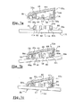
その理由は、図7a〜図7cに示された本発明の1つの特徴によれば、アーム22の前端部22aは、2つの垂直横方向リブ84を備え、これらのリブは、頂部ウェブ48の底面48iから垂直下方に延び、側面部50を接続しているからである。
The reason for this is that, according to one feature of the invention shown in FIGS. 7 a-7 c, the
アーム22の前端部により、コネクタ24が取り付け位置にあるとき、横方向リブがコネクタ24の各側で延びるように、頂部ウェブ48に対して横方向リブ84が、長手方向に配置されている。
With the front end of the
更にコネクタ24は、その本体38から垂直上方に延びる垂直長手方向側面部80を有し、このコネクタの頂部エッジは、傾斜して形状が一致している。
The
従って、コネクタがアーム22の前端部22aに対して、長手方向に正しく位置決めされていない場合に、ピボット56をハウジング62に挿入すると、リブ84の底部エッジ84iが、側面部80の頂部エッジ80sに当接するので、コネクタの長手方向の位置決めが正しくなく、コネクタ24を長手方向に移動しなければならないことが、ユーザーには判る。
Therefore, when the
更に、各側面部80の頂部エッジ80sは、傾斜部として形状が一致しているので、リブ84の底部エッジ84iが、関連する側面部80の頂部エッジ80sに当接すると、ユーザーに伝わるコネクタ24の垂直の挿入力により、コネクタ24は、ピボット56をハウジング62に挿入できる正しい位置に向かって、アーム22の前端部22aに対して長手方向に移動させられる。
Further, since the
変形実施例(図示せず)においては、アーム22の前端部22aに対するコネクタ24の長手方向の位置決めは、まず、ピボット56の後方に位置するリブ84によって達成され、次に、頂部ウェブ48を前方に延長している垂直横方向側面部52によって達成される。
In a variant embodiment (not shown), the longitudinal positioning of the
この変形例によれば、アーム22は、1つのリブ84しか有せず、これによってアーム22の製造が簡略化され、軽量化されている。
According to this modification, the
特に摩耗状態をチェックするために、ユーザーがブレード20を操作したいとき、ユーザーは、ドライブヘッドに対し、アーム22を枢動させることによって、ワイプすべき窓ガラスからブレード20を離間させる。次に、このブレード20は、軸線Aを中心として、アーム22に対して自由に枢動できるが、この枢動の大きさは一般に大きく、ユーザーにとって比較的大きい問題である。
When the user wants to manipulate the
その理由は、コネクタ24とアーム22とが、軸線Aを中心とするコネクタ24の枢動量を制限するための手段を含むからである。
This is because the
図7bから判るように、第1の方向、本例では、三角方向の枢動の大きさは、横方向リブ84、本例では、ピボット56の後方に位置する横方向リブ84の底部エッジ84iにスクレイパー26のヒール30の頂部面30sが当接するという点で、制限されている。
As can be seen from FIG. 7b, the magnitude of the pivot in the first direction, in this example the triangular direction, is the
図7cから判るように、第2の方向、すなわち逆三角方向の枢動の大きさは、ハウジング62の前方に位置するコネクタ24の側面部80の頂部エッジ80sが、アーム22の頂部ウェブ48の底面48iに当接することによって制限されている。
As can be seen from FIG. 7 c, the magnitude of the pivoting in the second direction, ie, the inverted triangular direction, is such that the
本発明の一実施例によれば、ピボット56の後方に位置する横方向リブ84の底部エッジ84iは、頂部ウェブ48の底面48iから垂直に延び、ハウジング62の前方に位置する側面部80の頂部エッジ80sが、コネクタ24の本体38の頂面38sから延びるので、一方向または他方向への、アーム22に対するブレード20の枢動の大きさは、所定の角度となっている。このように、角度が所定の大きさになっていることにより、窓ガラス上の各ポイントにおける窓ガラスへのアーム22の当接を維持することができる。この所定の角度は、10度であることが好ましい。
According to one embodiment of the present invention, the
本発明の一実施例によれば、コネクタ24は、横方向垂直中心平面に対しても対称であるので、側面部60、特にその頂部エッジ80sは、この中心平面に対して対称的となっている。
According to one embodiment of the invention, the
このような対称性によって、ユーザーは、取り付け時に、アーム22に対するコネクタ24の向きをチェックしなくてもよいので、ユーザーにとって時間を短縮でき、取り付けを簡略にできるだけでなく、工場における最初の組み立て時間も短縮できる。
This symmetry allows the user not to check the orientation of the
ここで、アーム22に対するブレード20の枢動の大きさの制限は、枢動運動に従って異なる手段によって達成される。しかし、枢動の大きさを制限するための手段は、本発明の範囲から逸脱することなく、2つの枢動方向に対して同一でもよいし、2つの枢動方向に対して逆でもよい。
Here, limiting the magnitude of the pivoting movement of the
更に、アーム22に対する、逆三角方向のブレード20の枢動の大きさの制限は、横方向リブ84、または頂部ウェブ48を前方に延長する垂直横方向側面部52にのいずれによっても達成できる。
Further, limiting the magnitude of the pivoting of the inverted
プラスチック成形により、一体に製造されるコネクタとドライブアームは、これらの部品の製造コストを下げ、かつワイパー機構の組み立て時間を短縮することができる。 The plastic molding and the integrally manufactured connector and drive arm can reduce the manufacturing cost of these parts and the assembly time of the wiper mechanism.
20 ワイパーアーム
22 ワイパーアーム
22a 長手方向前方端部
24 コネクタ
26 スクレイパー
28 ブレード
30 固定ヒール
32 ストリップ
34 せきつい部材
40 フック
48 頂部ウェブ
50 側面部
56 ピボット
58 支持要素
60 第2支持要素
62 相補的ハウジング
64 クランプ
78 ガイドリブ
80 側面部
84 リブ
20
Claims (24)
前記コネクタ(24)はほぼ水平の本体(38)を備え、この本体の底面(38i)は、前記ブレード(20)のワイパーゴム(26)を支持する構造要素(34)に前記ブレード(20)を固定するためのフック(40)を支持しており、
前記コネクタ本体(38)の頂面(38s)は、前記横方向関節接続軸線(a)を中心とする、前記アーム(22)の端部(22a)との関節接続手段(46a)を支持しており、
前記アームの端部は、ウェブを備え、このウェブは、前記コネクタの上方において、ほぼ水平に延び、前記横方向関節接続軸線(a)を中心とする前記コネクタ(24)の関節接続手段(46b)を支持しており、
前記アーム(22)の端部(22a)との前記コネクタ(46a)(46b)の関節接続手段は、前記横方向関節接続軸線(a)と同心状の横方向軸線を有する少なくとも1つのピボット(56)を備え、前記ピボットは、前記アーム(22)の端部(22a)に属すか、または前記コネクタ(24)に属す関連する第1支持要素(58)の側面(58a)から横方向に延び、コネクタ(24)に属すか、または前記アーム(22)の端部にそれぞれ属す関連する第2支持要素(60)に設けられた相補的ハウジング(62)内に嵌合できるようになっており、
前記第1支持要素(58)または前記第2支持要素(60)は、前記関連するハウジング(62)上の前記ピボット(56)の挿入を可能にし、かつ前記ハウジング(62)内に、前記ピボット(56)の自動ラジアルロッキングを生じさせる弾性変形可能な要素を備え、
前記第1支持要素(58)および第2支持要素(60)は、プラスチック材料を成形することによって、前記アーム(22)または前記コネクタ(24)とそれぞれ一体に製造されている自動車用ワイパーにおいて、
前記アーム(22)の端部(22a)は、前記関節接続手段(56)とは異なる、前記コネクタを長手方向に位置決めするための手段(52)(84)を備えていることを特徴とする自動車用ワイパー。 An automotive wiper comprising a wiper blade (20) attached so as to be articulated at a longitudinal front end (22a) of a wiper arm (22) around a horizontal horizontal axis (a) by a connector (24) Because
The connector (24) comprises a substantially horizontal body (38), the bottom surface (38i) of which is attached to the structural element (34) that supports the wiper rubber (26) of the blade (20). Supports the hook (40) for fixing
The top surface (38s) of the connector body (38) supports joint connection means (46a) with the end (22a) of the arm (22) centered on the lateral joint connection axis (a). And
The end of the arm comprises a web, the web extending substantially horizontally above the connector and articulating means (46b) of the connector (24) about the transverse articulation axis (a). )
The joint connection means of the connector (46a) (46b) with the end (22a) of the arm (22) is at least one pivot having a lateral axis concentric with the lateral joint connection axis (a). 56), the pivot belonging to the end (22a) of the arm (22) or laterally from the side (58a) of the associated first support element (58) belonging to the connector (24) Extends and can be fitted into a complementary housing (62) provided in an associated second support element (60) belonging to the connector (24) or respectively belonging to the end of the arm (22). And
The first support element (58) or the second support element (60) allows insertion of the pivot (56) on the associated housing (62) and within the housing (62) the pivot (56) comprising an elastically deformable element that produces automatic radial locking;
In the automotive wiper, the first support element (58) and the second support element (60) are each integrally manufactured with the arm (22) or the connector (24) by molding a plastic material.
The end (22a) of the arm (22) includes means (52) (84) for positioning the connector in the longitudinal direction, which is different from the joint connecting means (56). Wiper for automobiles.
Applications Claiming Priority (2)
| Application Number | Priority Date | Filing Date | Title |
|---|---|---|---|
| FR0214488A FR2847221B1 (en) | 2002-11-19 | 2002-11-19 | VEHICLE WIPER COMPRISING A ARTICULATING ARM AND CONNECTOR PRODUCED BY A PIECE BY MOLDING PLASTIC MATERIAL |
| PCT/EP2003/012942 WO2004045931A1 (en) | 2002-11-19 | 2003-11-19 | Vehicle windscreen wiper comprising an arm and an articulating connector |
Publications (1)
| Publication Number | Publication Date |
|---|---|
| JP2006506268A true JP2006506268A (en) | 2006-02-23 |
Family
ID=32187743
Family Applications (1)
| Application Number | Title | Priority Date | Filing Date |
|---|---|---|---|
| JP2004552656A Pending JP2006506268A (en) | 2002-11-19 | 2003-11-19 | Windshield wiper for automobile having arm and articulation connector |
Country Status (10)
| Country | Link |
|---|---|
| US (1) | US20060248675A1 (en) |
| EP (1) | EP1641663B1 (en) |
| JP (1) | JP2006506268A (en) |
| CN (1) | CN100422005C (en) |
| AT (1) | ATE430073T1 (en) |
| AU (1) | AU2003286175A1 (en) |
| DE (1) | DE60327473D1 (en) |
| FR (1) | FR2847221B1 (en) |
| MX (1) | MXPA05005320A (en) |
| WO (1) | WO2004045931A1 (en) |
Cited By (1)
| Publication number | Priority date | Publication date | Assignee | Title |
|---|---|---|---|---|
| JP2014169081A (en) * | 2007-05-31 | 2014-09-18 | Valeo Systemes D'essuyage | Adapter and connection base of connector for wiper blade of automobile |
Families Citing this family (45)
| Publication number | Priority date | Publication date | Assignee | Title |
|---|---|---|---|---|
| EP1681216B1 (en) * | 2005-01-14 | 2008-02-27 | Federal-Mogul S.A. | Windshield wiper device |
| DE102005020601A1 (en) * | 2005-05-03 | 2006-11-16 | Robert Bosch Gmbh | Device for articulating a wiper blade with a wiper arm |
| FR2890924B1 (en) * | 2005-09-21 | 2010-02-12 | Valeo Systemes Dessuyage | CONNECTOR FOR ASSEMBLING A WIPER BOSS ON A CROSSBAR ROD |
| FR2893896B1 (en) * | 2005-11-30 | 2008-02-01 | Valeo Systemes Dessuyage | MOUNTING BRACKET FOR A WIPER BLADE ON A TRAINING ARM REALIZED IN PLATED SHEET |
| US20080028564A1 (en) * | 2006-08-04 | 2008-02-07 | Shu-Lan Ku | Wiper blade support structure |
| US8122560B2 (en) * | 2006-08-04 | 2012-02-28 | Dongguan Hongyi Wiper Co., Ltd. | Windshield wiper bridge base assembly |
| FR2924079B1 (en) * | 2007-11-28 | 2010-04-02 | Valeo Systemes Dessuyage | PLATFORM FOR CONNECTING A WIPER BLADE FOR A MOTOR VEHICLE |
| DE102008000933A1 (en) * | 2008-04-02 | 2009-10-08 | Robert Bosch Gmbh | Device for articulating a wiper blade with a wiper arm |
| DE102008040848A1 (en) | 2008-07-30 | 2010-02-04 | Robert Bosch Gmbh | Windscreen wiper device, has arm system with housing for receiving fixation element of blade system, and cavities forming spacer elements respectively with housing for introducing and hooking fixation element in housing |
| DE102009002783A1 (en) * | 2009-05-04 | 2010-11-11 | Robert Bosch Gmbh | Connecting device for connecting a wiper arm with a wiper blade |
| DE102010062925A1 (en) * | 2010-12-13 | 2012-06-14 | Robert Bosch Gmbh | wiper device |
| US9174609B2 (en) | 2011-04-21 | 2015-11-03 | Pylon Manufacturing Corp. | Wiper blade with cover |
| US9457768B2 (en) | 2011-04-21 | 2016-10-04 | Pylon Manufacturing Corp. | Vortex damping wiper blade |
| WO2013016493A1 (en) | 2011-07-28 | 2013-01-31 | Pylon Manufacturing Corp. | Windshield wiper adapter, connector and assembly |
| US9108595B2 (en) | 2011-07-29 | 2015-08-18 | Pylon Manufacturing Corporation | Windshield wiper connector |
| FR2979876B1 (en) * | 2011-09-12 | 2013-09-27 | Valeo Systemes Dessuyage | CONNECTION ASSEMBLY FOR WIPING SYSTEM OF A MOTOR VEHICLE |
| CA2865292C (en) | 2012-02-24 | 2018-03-13 | Pylon Manufacturing Corp. | Wiper blade |
| US20130219649A1 (en) | 2012-02-24 | 2013-08-29 | Pylon Manufacturing Corp. | Wiper blade |
| DE102012107231A1 (en) * | 2012-08-07 | 2014-05-15 | Valeo Systèmes d'Essuyage | Wiper device and wiper arm for cleaning a vehicle window |
| US10829092B2 (en) | 2012-09-24 | 2020-11-10 | Pylon Manufacturing Corp. | Wiper blade with modular mounting base |
| US20140101882A1 (en) * | 2012-10-15 | 2014-04-17 | Trico Products Corporation | Rear windshield wiper arm assembly with service up detent position |
| US10166951B2 (en) | 2013-03-15 | 2019-01-01 | Pylon Manufacturing Corp. | Windshield wiper connector |
| EP3019373B1 (en) * | 2013-07-09 | 2017-08-23 | Federal-Mogul S.a. | Windscreen wiper device |
| EP3065980B1 (en) | 2013-11-06 | 2018-12-19 | Federal-Mogul Motorparts Corporation | Rear windscreen wiper device |
| WO2015069925A1 (en) | 2013-11-06 | 2015-05-14 | Federal-Mogul Motorparts Corporation | Windscreen wiper device |
| FR3013292B1 (en) * | 2013-11-21 | 2017-02-17 | Valeo Systemes Dessuyage | CONNECTOR FOR A WIPER BLADE OF A WINDOW SYSTEM OF A GLASS OF A VEHICLE AND WIPING SYSTEM THUS EQUIPPED |
| US9505380B2 (en) | 2014-03-07 | 2016-11-29 | Pylon Manufacturing Corp. | Windshield wiper connector and assembly |
| USD787308S1 (en) | 2014-10-03 | 2017-05-23 | Pylon Manufacturing Corp. | Wiper blade package |
| USD777079S1 (en) | 2014-10-03 | 2017-01-24 | Pylon Manufacturing Corp. | Wiper blade frame |
| FR3037898A1 (en) * | 2015-06-29 | 2016-12-30 | Valeo Systemes Dessuyage | ORGAN FOR A CONNECTION SYSTEM FROM A WIPER TO A WIPER ARM |
| JP6055044B1 (en) * | 2015-07-27 | 2016-12-27 | 日本ワイパブレード株式会社 | Wiper assembly |
| FR3041306B1 (en) * | 2015-09-22 | 2019-05-03 | Valeo Systemes D'essuyage | CONNECTOR FOR WIPER BLADE FOR MOTOR VEHICLE |
| WO2017075066A1 (en) | 2015-10-26 | 2017-05-04 | Pylon Manufacturing Corp. | Wiper blade |
| FR3043619B1 (en) * | 2015-11-17 | 2019-05-24 | Valeo Systemes D'essuyage | ADAPTER, CONNECTOR AND ASSEMBLY FORMED OF SUCH A CONNECTOR AND SUCH ADAPTER FOR A WIPER. |
| FR3043618B1 (en) * | 2015-11-17 | 2017-12-15 | Valeo Systemes Dessuyage | TRAINING ARM ASSEMBLY AND CONNECTOR FOR WIPER. |
| FR3043620B1 (en) | 2015-11-17 | 2019-01-25 | Valeo Systemes D'essuyage | INTERMEDIATE PIECE FOR CONNECTING A WIPER BLADE TO A DRIVING ARM OF A WINDSCREEN WIPER |
| CN109715449A (en) | 2016-05-19 | 2019-05-03 | 电缆塔制造有限公司 | Windscreen wiper connector |
| CN109311452A (en) | 2016-05-19 | 2019-02-05 | 电缆塔制造有限公司 | Windscreen wiper connector |
| EP3458315B1 (en) | 2016-05-19 | 2021-09-08 | Pylon Manufacturing Corp. | Windshield wiper blade |
| AU2017268019A1 (en) | 2016-05-19 | 2018-11-22 | Pylon Manufacturing Corp. | Windshield wiper connector |
| US11040705B2 (en) | 2016-05-19 | 2021-06-22 | Pylon Manufacturing Corp. | Windshield wiper connector |
| US20180037196A1 (en) * | 2016-08-04 | 2018-02-08 | Federal-Mogul Motorparts Corporation | Windscreen wiper device |
| WO2018081791A1 (en) | 2016-10-31 | 2018-05-03 | Pylon Manufacturing Corp. | Wiper blade with cover |
| CN107196163B (en) * | 2017-01-23 | 2019-06-18 | 番禺得意精密电子工业有限公司 | Electric connector |
| FR3072629B1 (en) * | 2017-10-20 | 2019-10-11 | Valeo Systemes D'essuyage | ADAPTER FOR A MOTOR VEHICLE WIPER AND ASSEMBLY COMPRISING SUCH AN ADAPTER |
Family Cites Families (10)
| Publication number | Priority date | Publication date | Assignee | Title |
|---|---|---|---|---|
| CN2309256Y (en) * | 1997-08-15 | 1999-03-03 | 洪信耀 | Structure-improved wiper connector |
| DE19860644A1 (en) * | 1998-12-29 | 2000-07-06 | Bosch Gmbh Robert | Device for the articulated connection of a wiper blade for windows of motor vehicles with a wiper arm and method for producing this connection |
| DE19907629A1 (en) * | 1999-02-23 | 2000-08-24 | Bosch Gmbh Robert | Pivot-connection for windscreen wiper blade of motor vehicle has strip-type spring-elastic metal support rail to hold wiper strip and elastic plastic coupling element installed on upper side facing away from windscreen |
| DE19952054A1 (en) * | 1999-10-28 | 2001-05-03 | Bosch Gmbh Robert | Wiper device for windows of motor vehicles |
| DE10039291A1 (en) * | 2000-08-11 | 2002-03-14 | Valeo Auto Electric Gmbh | Wiper system esp. for motor vehicles has open fitting channel and link pins fitted into bearing recesses via channel |
| DE10043427B4 (en) * | 2000-09-04 | 2010-09-23 | Valeo Wischersysteme Gmbh | wiper device |
| DE10046439A1 (en) * | 2000-09-20 | 2002-04-04 | Bosch Gmbh Robert | windshield wipers |
| WO2002034592A1 (en) * | 2000-10-28 | 2002-05-02 | Robert Bosch Gmbh | Device for detachably and hingedly connecting a wiper blade for cleaning panes to a wiper arm |
| DE10057253A1 (en) * | 2000-11-18 | 2002-05-23 | Bosch Gmbh Robert | Wiper lever for motor vehicle's windscreen wiper system has cap for covering connecting section between wiper blade and wiper arm and in cross section is approximately U-shape and made from elastic plastic |
| ES2244556T3 (en) * | 2000-12-28 | 2005-12-16 | Robert Bosch Gmbh | DEVICE FOR THE REMOVABLE UNION OF A WINDSHIELD WASHER WITH A WINDSHIELD ARM. |
-
2002
- 2002-11-19 FR FR0214488A patent/FR2847221B1/en not_active Expired - Fee Related
-
2003
- 2003-11-19 JP JP2004552656A patent/JP2006506268A/en active Pending
- 2003-11-19 MX MXPA05005320A patent/MXPA05005320A/en unknown
- 2003-11-19 WO PCT/EP2003/012942 patent/WO2004045931A1/en active Application Filing
- 2003-11-19 DE DE60327473T patent/DE60327473D1/en not_active Expired - Lifetime
- 2003-11-19 AU AU2003286175A patent/AU2003286175A1/en not_active Abandoned
- 2003-11-19 US US10/535,534 patent/US20060248675A1/en not_active Abandoned
- 2003-11-19 EP EP03776911A patent/EP1641663B1/en not_active Expired - Lifetime
- 2003-11-19 AT AT03776911T patent/ATE430073T1/en not_active IP Right Cessation
- 2003-11-19 CN CNB2003801036852A patent/CN100422005C/en not_active Expired - Fee Related
Cited By (1)
| Publication number | Priority date | Publication date | Assignee | Title |
|---|---|---|---|---|
| JP2014169081A (en) * | 2007-05-31 | 2014-09-18 | Valeo Systemes D'essuyage | Adapter and connection base of connector for wiper blade of automobile |
Also Published As
| Publication number | Publication date |
|---|---|
| ATE430073T1 (en) | 2009-05-15 |
| MXPA05005320A (en) | 2005-07-25 |
| CN1714015A (en) | 2005-12-28 |
| FR2847221A1 (en) | 2004-05-21 |
| CN100422005C (en) | 2008-10-01 |
| AU2003286175A1 (en) | 2004-06-15 |
| WO2004045931A1 (en) | 2004-06-03 |
| FR2847221B1 (en) | 2006-08-04 |
| EP1641663A1 (en) | 2006-04-05 |
| EP1641663B1 (en) | 2009-04-29 |
| US20060248675A1 (en) | 2006-11-09 |
| DE60327473D1 (en) | 2009-06-10 |
Similar Documents
| Publication | Publication Date | Title |
|---|---|---|
| JP2006506268A (en) | Windshield wiper for automobile having arm and articulation connector | |
| RU2469887C2 (en) | Connecting member for wiper brush articulation with its lever | |
| JP4313200B2 (en) | Automotive wiper with safety closure | |
| KR100660768B1 (en) | Wiping device for glass surfaces of motor vehicles | |
| KR100595354B1 (en) | Device for an articulated connection between a wiper blade for panels of glass in motor vehicles and a wiper arm | |
| JP4856714B2 (en) | Joint arm made of plastic | |
| US7832046B2 (en) | Coupling apparatus of wiper arm | |
| US9233665B2 (en) | Wiper blade | |
| US7203990B2 (en) | Wiper blade | |
| KR20010099977A (en) | Wiper device for motor vehicle panes | |
| BRPI0617185A2 (en) | windshield wiper arm | |
| MXPA06002308A (en) | A windscreen wiper arm. | |
| JP2006298351A (en) | Wiper connector cap | |
| KR20000069490A (en) | Windshield wiper | |
| CN103687758A (en) | Connecting device for the articulated connection of a wiper blade to a wiper arm, and an adaptor | |
| KR101766944B1 (en) | Windscreen wiper device | |
| US20160082929A1 (en) | Wiper blade | |
| US20130305479A1 (en) | Wiper blade | |
| CN113382895B (en) | Adapter for a motor vehicle windscreen wiper blade | |
| CN210122104U (en) | Wiper blade and wiper | |
| KR100705663B1 (en) | Wiper blade | |
| CN209852263U (en) | Wiper blade and wiper | |
| JP2009113709A (en) | Vehicular wiper | |
| JP5134852B2 (en) | Window glass wiper | |
| KR20060025144A (en) | Wiper arm for windscreen wiper |
Legal Events
| Date | Code | Title | Description |
|---|---|---|---|
| A621 | Written request for application examination |
Free format text: JAPANESE INTERMEDIATE CODE: A621 Effective date: 20061116 |
|
| A131 | Notification of reasons for refusal |
Free format text: JAPANESE INTERMEDIATE CODE: A131 Effective date: 20090519 |
|
| A601 | Written request for extension of time |
Free format text: JAPANESE INTERMEDIATE CODE: A601 Effective date: 20090807 |
|
| A602 | Written permission of extension of time |
Free format text: JAPANESE INTERMEDIATE CODE: A602 Effective date: 20090814 |
|
| A02 | Decision of refusal |
Free format text: JAPANESE INTERMEDIATE CODE: A02 Effective date: 20100223 |