JP2006348656A - Girder structure and its construction method - Google Patents
Girder structure and its construction method Download PDFInfo
- Publication number
- JP2006348656A JP2006348656A JP2005178026A JP2005178026A JP2006348656A JP 2006348656 A JP2006348656 A JP 2006348656A JP 2005178026 A JP2005178026 A JP 2005178026A JP 2005178026 A JP2005178026 A JP 2005178026A JP 2006348656 A JP2006348656 A JP 2006348656A
- Authority
- JP
- Japan
- Prior art keywords
- girder
- floor slab
- side plate
- members
- floor
- Prior art date
- Legal status (The legal status is an assumption and is not a legal conclusion. Google has not performed a legal analysis and makes no representation as to the accuracy of the status listed.)
- Granted
Links
Images


Abstract
Description
本発明は、橋梁や人工地盤等の橋脚等の上に架け渡される桁構造及びその施工方法に関するものである。 The present invention relates to a girder structure spanned on a bridge pier such as a bridge or artificial ground, and a construction method thereof.
従来、橋梁の上部工としての桁構造の軽量化を目的として、プレストレストコンクリートで製作された上床版と下床版との間を波型鋼板で繋いだ複合構造の桁構造が知られている(特許文献1等参照)。 Conventionally, for the purpose of reducing the weight of the girder structure as a bridge superstructure, a composite girder structure in which a corrugated steel plate is used to connect the upper and lower floor slabs made of prestressed concrete is known ( (See Patent Document 1).
この複合構造の桁構造は、床版部と同じようにコンクリートによって製作されていた桁構造のウェブ部(桁部材)を波型鋼板に置き換えることによって自重を大幅に軽減できるもので、それに伴って下部工を合理化して全体の工期及び工費を削減することが可能になる。
しかしながら、従来の桁構造のように鋼材を使用した複合構造の場合、腐食を防止するための維持管理費がコンクリート構造物に比べて増加する上に、コンクリートと鋼材との接合部の構造及び維持管理が複雑になる。 However, in the case of a composite structure using steel as in the conventional girder structure, the maintenance cost for preventing corrosion increases compared to a concrete structure, and the structure and maintenance of the joint between concrete and steel Management becomes complicated.
一方、プレストレストコンクリート又は鉄筋コンクリートだけで桁構造を構築した場合、上部工の自重が大きくなるのでスパン長をあまり長く出来なくなる上に、橋脚などの下部工の規模も大きくなって全体の工事費が増加する。 On the other hand, when a girder structure is constructed using prestressed concrete or reinforced concrete alone, the superstructure's own weight increases, so the span length cannot be made too long, and the scale of substructure such as bridge piers also increases, increasing the overall construction cost. To do.
そこで、本発明は、桁構造の軽量化が図れると共に維持管理が容易な桁構造及びその施工方法を提供することを目的としている。 Accordingly, an object of the present invention is to provide a girder structure that can reduce the weight of the girder structure and is easy to maintain and a construction method thereof.
前記目的を達成するために、本発明は、間隔を置いて複数並列される桁部材とその上端面間及び下端面間が床版で連結される桁構造であって、圧縮強度が150N/mm2以上、曲げ引張強度が25N/mm2以上、割裂引張強度が10N/mm2以上の力学的特性をもつ繊維補強セメント系混合材料によって形成され、前記床版は、鉄筋コンクリート又はプレストレストコンクリートによって形成されている桁構造であることを特徴とする。 In order to achieve the above object, the present invention provides a girder structure in which a plurality of girder members arranged in parallel at intervals and the upper end surface and the lower end surface thereof are connected by a floor slab, and the compressive strength is 150 N / mm. 2 or more, flexural tensile strength 25 N / mm 2 or more, split tensile strength is formed by fiber reinforced cementitious composite material with 10 N / mm 2 or more mechanical properties, the slab is formed by concrete or prestressed concrete It is characterized by having a girder structure.
ここで、前記桁部材は、セメントと、最大粒度径が2.5mm以下の骨材粒子と、ポゾラン系反応粒子と、分散剤とを含有する組成物を水と混合することにより得られるセメント系マトリックスに、直径が0.1〜0.3mm、長さが10〜30mmの形状の繊維を全容積の1〜4%混入することで得ることができる。 Here, the girder member is a cement matrix obtained by mixing a composition containing cement, aggregate particles having a maximum particle size of 2.5 mm or less, pozzolanic reaction particles, and a dispersant with water. Further, it can be obtained by mixing 1 to 4% of the total volume of fibers having a diameter of 0.1 to 0.3 mm and a length of 10 to 30 mm.
また、前記桁部材は、内部に中空部又は軽量部材が配設された軽量部が形成された構成とすることができる。 Moreover, the said girder member can be set as the structure by which the lightweight part by which the hollow part or the lightweight member was arrange | positioned was formed.
さらに、前記桁部材と前記床版とは双方に埋設される接合部材によって接合されており、前記接合部材は、前記桁部材の長手方向に延設されると共に穴を開口した桁側板状部と、該桁側板状部と平面視で略直交すると共に穴を開口した床版側板状部とを有するように構成することができる。 Furthermore, the said girder member and the said floor slab are joined by the joining member embed | buried under both, The said joining member is extended in the longitudinal direction of the said girder member, and the girder side plate-shaped part which opened the hole, and The slab side plate-like portion can be configured to have a floor slab-side plate-like portion that is substantially orthogonal to the girder-side plate-like portion and has a hole.
また本発明は、上記桁構造の施工方法であって、前記接合部材の桁側板状部を上端部及び下端部に埋設した桁部材を前記繊維補強セメント系混合材料によって予め製作し、所定の位置に前記桁部材が並列されるように複数設置し、前記桁部材とその長手方向に予め設置された桁部材との間をそれらの桁部材に挿通させた緊張材によって一体化し、前記接合部材の床版側板状部と並列されるように床版用の主鉄筋を配置し、コンクリートを打設して床版を構築する桁構造の施工方法であることを特徴とする。 Further, the present invention is a construction method for the above-mentioned girder structure, wherein a girder member in which a girder-side plate-like portion of the joining member is embedded in an upper end portion and a lower end portion is manufactured in advance by the fiber-reinforced cement-based mixed material, and a predetermined position is obtained. A plurality of girder members are installed in parallel to each other, and the girder member and a girder member previously installed in the longitudinal direction thereof are integrated with a tension member inserted through the girder members, It is a construction method of a girder structure in which main reinforcing bars for floor slabs are arranged so as to be juxtaposed with the floor slab side plate-like portion, and concrete is placed to construct the floor slab.
さらに、上記桁構造の施工方法であって、前記接合部材の桁側板状部を上端部及び下端部に埋設した桁部材を前記繊維補強セメント系混合材料によって予め製作すると共に、前記接合部材の床版側板状部が配設される位置に床開口部を設けた床版を鉄筋コンクリート又はプレストレストコンクリートによって予め製作し、前記桁部材の下端面間を連結させる下側の前記床版を所定の位置に設置し、その上に前記床版側板状部が前記床開口部に収容されるように前記桁部材を複数設置し、前記桁部材とその長手方向に予め設置された桁部材との間をそれらの桁部材に挿通させた緊張材によって一体化し、前記桁部材の上端面から上方に突起した前記床版側板状部が前記床開口部に収容されるように上側の前記床版を前記桁部材上に載置し、前記床開口部に充填材を充填して前記桁部材と前記床版とを接合する桁構造の施工方法であることを特徴とする。 Further, in the construction method of the girder structure, a girder member in which a girder side plate-like portion of the joining member is embedded in an upper end portion and a lower end portion is manufactured in advance using the fiber-reinforced cement-based mixed material, and the floor of the joining member A floor slab provided with a floor opening at a position where the plate side plate-like portion is disposed is manufactured in advance using reinforced concrete or prestressed concrete, and the lower floor slab that connects the lower end surfaces of the girder members is placed at a predetermined position. A plurality of the girder members are installed so that the floor slab side plate-like portion is accommodated in the floor opening, and a space between the girder member and a girder member previously installed in the longitudinal direction thereof is installed. The upper slab is integrated with a tension member inserted through the spar member, and the upper slab is placed in the floor opening so that the floor slab side plate-like portion protruding upward from the upper end surface of the spar member is accommodated in the floor opening. Placed on the By filling the filler opening characterized in that it is a construction method of the girder structure which bonding the slab and the beam members.
このように構成された本発明は、高強度の繊維補強セメント系混合材料で形成された桁部材と、鉄筋コンクリート又はプレストレストコンクリートによって形成された上下の床版とによって閉断面を有する桁構造が構成されている。 In the present invention configured as described above, a girder structure having a closed cross section is configured by a girder member formed of a high-strength fiber-reinforced cement-based mixed material and upper and lower floor slabs formed of reinforced concrete or prestressed concrete. ing.
このため、桁構造を鉄筋コンクリート又はプレストレストコンクリートだけで構築されたものより軽量にすることができる上に、セメント系混合材料だけで外面が形成されるので腐食の心配がほとんどなく維持管理費を削減することができる。 For this reason, the girder structure can be made lighter than that constructed only with reinforced concrete or prestressed concrete, and since the outer surface is formed only with cementitious mixed material, there is almost no concern about corrosion, reducing maintenance costs. be able to.
また、前記桁部材の内部を中空部又は軽量部とすることで、桁部材の自重をさらに軽量化することができるので長スパン化が可能になる。 Moreover, since the inside of the said girder member is made into a hollow part or a lightweight part, since the weight of a girder member can be further reduced in weight, a long span is attained.
さらに、桁側板状部と床版側板状部とが一体になった接合部材を、穴を開口した桁側板状部を桁部材の長手方向に沿って埋設するとともに、それと略直交する方向に向けた穴を開口した床版側板状部材を床版に埋設する。 Further, the joining member in which the girder side plate-like portion and the floor slab side plate-like portion are integrated is embedded along the longitudinal direction of the girder member with the hole-opening girder-side plate-like portion and directed in a direction substantially orthogonal thereto. The floor slab side plate-like member having a hole is embedded in the floor slab.
このため、桁部材の幅方向に占める前記桁側板状部材の割合が小さいので桁部材の幅を小さくすることができる。 For this reason, since the ratio of the said girder side plate-shaped member which occupies in the width direction of a girder member is small, the width | variety of a girder member can be made small.
また、前記床版の主鉄筋は、前記桁部材の長手直交方向に向けて配置されるため、前記床版側板状部材と主鉄筋の干渉を容易に回避することができる。 Further, since the main reinforcing bars of the floor slab are arranged in the longitudinal orthogonal direction of the girder member, it is possible to easily avoid the interference between the floor slab side plate-like member and the main reinforcing bars.
以下、本発明の最良の実施の形態について図面を参照して説明する。 The best mode for carrying out the present invention will be described below with reference to the drawings.
図1は、橋梁や人工地盤等の橋脚等の上に架け渡される桁構造100の概略斜視図を示したものである。
FIG. 1 is a schematic perspective view of a
まず構成から説明すると、本実施の形態の桁構造100は、複数並列された桁部材1,1と、その上端面間を連結させる上床版2Aと、桁部材1,1の下端面間を連結させる下床版2Bと、桁部材1,1と上床版2A及び下床版2Bとの接合構造を構成する接合部材3とから主に構成される。
First, the structure of the
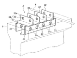
また図2は、この接合部材3の詳細を示した拡大斜視図である。
FIG. 2 is an enlarged perspective view showing details of the joining
この接合部材3は、桁部材1に埋設される板状の桁側板状部31,31と、上床版2A又は下床版2Bに埋設される板状の床版側板状部32,・・・と、桁側板状部31,31と床版側板状部32,・・・とを連結する連結部33,・・・とによって主に構成される。
This joining
この桁側板状部31は、例えば鋼板に複数の穴31a,・・・を開口して形成され、桁部材1の長手方向に向けて一方の桁側板状部31を延設すると共に、桁部材1の長手直交方向に間隔を置いて他方の桁側板状部31が並列される。
The girder-side plate-
本実施の形態では、床版側板状部32と連結部33とは断面視略L字型のL字型鋼材34に一体に形成されており、床版側板状部32には間隔を置いて穴32a,32aが複数開口されている。
In the present embodiment, the floor slab side plate-
このL字型鋼材34は、桁側板状部31,31に跨って溶接などで固定され、桁側板状部31,31の延設方向、すなわち桁部材1の長手方向に間隔を置いて複数配置される。
The L-
このようにして構成される接合部材3は、図2に示すように並列された2枚の桁側板状部31,31と4枚の床版側板状部32,・・・とが平面視で略直交しているため、桁側板状部31,31を桁部材1の長手方向に沿って配置すれば、床版側板状部32,・・・は桁部材1の長手直交方向に向くことになる。
As shown in FIG. 2, the joining
また、上床版2A(又は下床版2B)の主鉄筋4は桁部材1の長手直交方向に向けて配置されると共に、桁部材1の長手方向に間隔を置いて複数配置される。
Further, the main reinforcing bars 4 of the
すなわち、この上床版2A(又は下床版2B)の主鉄筋4は、図2に示すように接合部材3の床版側板状部32,・・・と同じ方向を向いて配置されるため、床版側板状部32,32の間に主鉄筋4を配置することで、これらとの干渉を容易に回避することができる。
That is, since the main reinforcing bars 4 of the
この接合部材3の周囲にはコンクリート等のセメント系混合材料が充填されることになるが、本実施の形態の桁部材1は、その中でも特に超高強度の繊維補強セメント系混合材料を使用して製作する。
The
この繊維補強セメント系混合材料は、セメントと、骨材粒子と、ポゾラン系反応粒子と、分散剤とを含有する組成物を水と混合することにより得られるセメント系マトリックスに、金属繊維を混入して製造する。 This fiber reinforced cementitious mixed material mixes metal fibers into a cementitious matrix obtained by mixing a composition containing cement, aggregate particles, pozzolanic reactive particles, and a dispersant with water. Manufactured.
ここで、前記骨材粒子には、最大粒度径が3.0mm以下、好ましくは2.5mm以下の硅砂等の骨材材料を使用する。また、ポゾラン系反応粒子には、粒子径が15μm以下のものを使用する。例えば、粒子径が0.01〜0.5μmの活性度の高いポゾラン系反応粒子としてシリカヒューム等を使用し、粒子径が0.1〜15μmの活性度の低いポゾラン系反応粒子としてフライアッシュや高炉スラグ等を使用する。これらの活性度の異なるポゾラン系反応粒子は、混合したり、単独で使用したりすることができる。また、前記分散剤は、流動性を高めるために少なくとも1種類使用する。 Here, an aggregate material such as cinnabar having a maximum particle size of 3.0 mm or less, preferably 2.5 mm or less is used for the aggregate particles. Further, as the pozzolanic reaction particles, those having a particle size of 15 μm or less are used. For example, silica fume or the like is used as a highly active pozzolanic reaction particle having a particle size of 0.01 to 0.5 μm, and fly ash or blast furnace slag is used as a low activity pozzolanic reaction particle having a particle size of 0.1 to 15 μm. To do. These pozzolanic reactive particles having different activities can be mixed or used alone. Further, at least one type of the dispersant is used in order to improve fluidity.
また、金属繊維には、例えば直径が0.1〜0.3mm程度で、長さが10〜30mm程度の形状の引張り降伏応力度が2600〜2800N/mm2の鋼繊維を使用する。さらに、この鋼繊維は、製造される繊維補強セメント系混合材料の全容積の1〜4%程度の量を混入させる。 For the metal fiber, for example, a steel fiber having a diameter of about 0.1 to 0.3 mm and a length of about 10 to 30 mm and a tensile yield stress of 2600 to 2800 N / mm 2 is used. Further, this steel fiber is mixed in an amount of about 1 to 4% of the total volume of the fiber-reinforced cementitious mixed material to be produced.
このような配合で製造される前記繊維補強セメント系混合材料によって形成された部材は、圧縮強度が150〜200N/mm2、曲げ引張強度が25〜45N/mm2、割裂引張強度が10〜25N/mm2、透水係数が4.0×10-17cm/sec、塩分拡散係数が0.0019cm2/年、弾性係数が50〜55GPaの特性を有する。 A member formed of the fiber-reinforced cement-based mixed material manufactured with such a composition has a compressive strength of 150 to 200 N / mm 2 , a bending tensile strength of 25 to 45 N / mm 2 , and a split tensile strength of 10 to 25 N. / Mm 2 , water permeability is 4.0 × 10 −17 cm / sec, salt diffusion coefficient is 0.0019 cm 2 / year, and elastic modulus is 50 to 55 GPa.
本実施の形態の桁部材1は、このような繊維補強セメント系混合材料によって工場などで断面視I型にエレメント毎に製作される。 The girder member 1 of the present embodiment is manufactured for each element in a cross-sectional view I-type at a factory or the like using such a fiber reinforced cementitious mixed material.
そして、桁構造100を構築する現場において図1に示すように桁部材1の長手方向に複数の桁部材1,・・・が延設され、その桁部材1,・・・を挿通させたPC鋼棒やPCケーブル等の緊張材5,・・・によって一体化される。
Then, at the site where the
また、主鉄筋4を配置して構築する上床版2A及び下床版2Bは、セメント系混合材料としてのコンクリートを使用して鉄筋コンクリート又はプレストレストコンクリートに形成される。
Further, the
本実施の形態の上床版2Aは、載置させる桁部材1,1の間隔より広い幅で形成されており、桁部材1,1を当接させる部分にはハンチが設けられている。
The
また、下床版2Bは、その上に載置する桁部材1,1の間隔と同じ幅で形成されており、桁部材1,1を当接させる部分にはハンチが設けられている。
Further, the
次に、本実施の形態の桁構造100の作用について説明する。
Next, the operation of the
この桁構造100は、桁部材1を強度が非常に高い前記繊維補強セメント系混合材料によって形成しているので断面を大幅に削減できる上に、桁部材1,1と上床版2A及び下床版2Bとによって閉断面が形成されて剛性が向上するので、一般の普通コンクリートで桁構造を構築した場合に比べて50%〜70%程度、桁構造100の自重を削減することができる。
In this
すなわち、本実施の形態の桁構造100のような箱桁タイプの構造における桁部材1の役割は、主として桁構造100に発生するせん断断面力に抵抗することである。
That is, the role of the girder member 1 in the box girder type structure such as the
一方、従来のように普通コンクリートで桁部材を構築する場合は、普通コンクリート自体のせん断抵抗に期待することになり、コンクリートで不足する分はせん断補強鉄筋(スターラップ)を配置して補うことになる。 On the other hand, when constructing a girder member with ordinary concrete as in the past, we would expect the shear resistance of ordinary concrete itself, and to compensate for the shortage of concrete by arranging shear reinforcing bars (star wrap). Become.
このようにせん断補強鉄筋を配置すると、その周囲にコンクリートのかぶりを確保する必要があるため部材厚が厚くなって自重が増加することになる。 When the shear reinforcing steel bars are arranged in this way, it is necessary to secure a concrete cover around the reinforcing steel bars, so that the member thickness is increased and the own weight is increased.
これに対して記繊維補強セメント系混合材料によって桁部材1を形成すれば、例えば2%程度混入された高強度の繊維が引張力に対して抵抗することになるので、せん断補強鉄筋を配置しなくとも充分にせん断耐力を確保でき、部材厚を薄くして自重を従来の30%〜50%に軽減することができる。 On the other hand, if the girder member 1 is formed from the fiber-reinforced cement-based mixed material, for example, high-strength fibers mixed in about 2% will resist the tensile force. Even if not, sufficient shear strength can be secured, and the thickness of the member can be reduced to reduce its own weight to 30% to 50%.
また、前記繊維補強セメント系混合材料は上述したように透水係数、塩分拡散係数が非常に小さいので、このような材料で形成された桁部材1は維持管理をほとんどしなくとも劣化することがほとんどない。 Further, since the fiber-reinforced cement-based mixed material has a very low water permeability coefficient and salt diffusion coefficient as described above, the girder member 1 formed of such a material is hardly deteriorated even with little maintenance. Absent.
さらに、上床版2A及び下床版2Bもコンクリートで形成されているので維持管理が容易である。
Furthermore, since the
また、桁部材1の断面積を小さく出来れば、緊張材5,・・・への緊張導入力が小さくても所望する緊張力(プレストレス)を桁部材1,・・・に導入することができる。 Moreover, if the cross-sectional area of the girder member 1 can be reduced, a desired tension (pre-stress) can be introduced into the girder members 1,. it can.
さらに、軽量化によって桁構造100のスパンの長大化も可能になるので、現場施工期間を短縮することができる。
Furthermore, since the span of the
また、前記した接合部材3は、桁側板状部31と床版側板状部32に穴31a,32aが開口されており、この穴31a,32aに充填される繊維補強セメント系混合材料又はコンクリートが上下方向及び長手方向のずれせん断力に対する抵抗となる。
Further, in the joining
さらに、桁側板状部31の穴31a,・・・に充填された繊維補強セメント系混合材料は、桁部材1の長手方向のずれせん断力に対する抵抗となる。
Further, the fiber reinforced cementitious mixed material filled in the
同様にして床版側板状部32の穴32a,32aに充填されたコンクリートは、桁部材1の長手直交方向のずれせん断力に対する抵抗となる。
Similarly, the concrete filled in the
また、桁側板状部31及び床版側板状部32は、板面に当接する繊維補強セメント系混合材料又はコンクリートの支圧抵抗となるため、面直交方向のずれせん断力に対する抵抗となる。
Moreover, since the girder side plate-
さらに、桁側板状部31,31を並列させることで、桁部材1の頭部に作用する回転モーメントに対して確実に回転を拘束することができる。また、上床版2A及び下床版2B内では、床版側板状部32に開口された2つの穴32a,32aが上下方向の引抜き力及び押込み力に抵抗して回転を拘束することができる。
Furthermore, by arranging the girder-side plate-
このように穴31a,32aに充填された繊維補強セメント系混合材料又はコンクリートの二面せん断抵抗と、桁側板状部31及び床版側板状部32の板状部の支圧抵抗とによって、ずれせん断力、引抜き力及び押込み力に抵抗することができるので、所望する接合力を確実に確保することができる。
Thus, the two-sided shear resistance of the fiber-reinforced cement-based mixed material or concrete filled in the
また、桁部材1の幅方向に対しては、桁側板状部31,31はその厚み分を占有するだけなので、桁側板状部31,31の占める割合が小さくなり桁部材1の断面を小さくできる。
Further, in the width direction of the girder member 1, the girder side plate-
さらに、ずれせん断剛性が高くなれば、桁部材1に曲げが作用した際に桁部材1と上床版2A(又は下床版2B)とが一体として挙動して発生するたわみを小さくすることができる。
Further, if the shear shear rigidity is increased, the deflection generated by the behavior of the girder member 1 and the
以下、前記した実施の形態の実施例1について説明する。なお、前記実施の形態で説明した内容と同一乃至均等な部分の説明については同一符号を付して説明する。 Hereinafter, Example 1 of the above-described embodiment will be described. The description of the same or equivalent parts as those described in the above embodiment will be given the same reference numerals.
この実施例1では、図3,4を参照しながら桁構造100の施工方法について説明する。
In the first embodiment, a construction method of the
まず、工場や現場近くの製作ヤードなどで、繊維補強セメント系混合材料によって桁部材1を製作する。この桁部材1を製作する際には、上端部及び下端部に接合部材3が配置されるようにする。
First, the girder member 1 is manufactured from a fiber-reinforced cement-based mixed material at a production yard near the factory or the site. When the girder member 1 is manufactured, the joining
この接合部材3は、桁側板状部31及び連結部33が桁部材1の上端面又は下端面よりも内側に埋設される高さに合わせて固定し、図3(図6参照)に示すように床版側板状部32,・・・が桁部材1の長手方向に間隔を置いて複数突出されるようにした後に、桁部材1用の繊維補強セメント系混合材料を周囲に充填することによって桁部材1と一体化させる。
As shown in FIG. 3 (see FIG. 6), the joining
また、桁部材1と上床版2A及び下床版2Bとの接合剛性を一層高めるために、桁部材1の養生が終了したら、その上端面及び下端面にエポキシ系あるいはアクリル系の樹脂などの接着剤を塗布し、その上に細砂や硅砂を散布して表面に凹凸をつけることが好ましい。
Further, in order to further increase the joining rigidity between the girder member 1 and the
そして、このようにして製作した桁部材1を現地に運搬し、図3に示すように所定の位置に桁部材1,1が並列されるように設置する。 And the girder member 1 manufactured in this way is conveyed to the field, and it installs so that the girder members 1 and 1 may be juxtaposed in a predetermined position as shown in FIG.
ここで、図3は、桁部材1A,1Aの上端面間と下端面間とを上床版2Aと下床版2Bとで連結して予め構築した桁構造100Aの前方に、桁構造100を延伸させる施工手順を説明する斜視図である。
Here, FIG. 3 shows that the
この設置済みの桁部材1A,1Aの前方に、運搬してきた桁部材1,1を設置し、既設の桁部材1Aと新設の桁部材1とを桁部材1A,1の長手方向に挿通させた緊張材5によって一体化させる。
The girder members 1 and 1 that have been transported are installed in front of the installed
この緊張材5は、図4に示すように、桁部材1の長手方向に貫通させたシース管5dの内部に挿通される両端にネジ溝が刻設されたPC鋼棒である。
As shown in FIG. 4, the
既設の桁部材1Aから延伸方向に突出した緊張材5のネジ溝には、接合用長ナット5cを半分程度まで螺入させておき、桁部材1Aの端面にエポキシ系あるいはアクリル系の樹脂などの接着剤7を塗布して新たな桁部材1を設置した後に、緊張材5を新設の桁部材1のシース管5dに挿入する。
In the thread groove of the
この緊張材5の一端は接合用長ナット5cに螺入させ、反対側の端部は緊張ジャッキ(図示せず)で引っ張った状態で定着ナット5aを締め付けて、桁部材1の製作時に埋設させた支圧プレート5bに対して緊張材5を定着させる。
One end of the
そして、桁部材1の側面に設けたシース管5dに連通する注入口5eからセメントミルクなどの注入材5gを注入する作業を、空気穴5fから注入材5gが溢れ出るまで続けると、接合用長ナット5cや緊張材5の周囲が注入材5gによって被覆されて防食できると共に、注入材5gとの付着によって緊張材5と桁部材1を一体化させることができる(図4右側の桁部材1Aに配設されたシース管5dの内部を参照)。
When the operation of injecting the
また、桁部材1A,1の接合部付近のシース管5dの拡幅部(図4の接合用長ナット5c周辺)に前記繊維補強セメント系混合材料を充填することで、接合部にせん断キーを形成することもできる。
Further, by filling the widened portion of the
このようにして桁部材1A,1間を一体化した後に、桁部材1,1の下端面間を連結させる下床版2Bの下面を形成するための型枠6を設置する。この型枠6上には下床版2B用の主鉄筋(図示せず)を配置して鉄筋コンクリート製又はプレストレストコンクリート製の下床版2Bを構築する。
After the
また、桁部材1,1の上端面間にも上床版2Aを構築するために、上床版2Aの下面を形成するための図示しない型枠を設置し、主鉄筋を床版側板状部32,・・・間に桁部材1の長手直交方向を向くようにして配置する。
Further, in order to construct the
また、桁部材1の長手方向に向けて配置される鉄筋(図示せず)は、穴32a,・・・に挿通させて配置し、既設の上床版2Aから前方に向けて突出した接合鉄筋41,・・・に重ねることで、上床版2Aの延伸方向の接合をおこなうことができる。
Moreover, the reinforcing bar (not shown) arrange | positioned toward the longitudinal direction of the girder member 1 is inserted and arrange | positioned through the
そして、この状態で上床版2A用のコンクリートを充填することによって、プレキャスト製の桁部材1,1と現場でコンクリートを打設して構築される上床版2A及び下床版2Bとによって構成される桁構造100が完成する。
And by filling the concrete for
このように単位長さ(エレメント長さ)の桁構造100を構築した後は、カンチレバー工法であれば上床版2A及び下床版2Bのコンクリートが所定の強度に達した後に、プレストレスを導入して次のエレメントに移動する。
After constructing the
また、総足場架設工法であれば、単位長さ毎に緊張する必要はなく、全体の桁構造100が完成した後に緊張をおこなえばよい。
Moreover, if it is a total scaffold construction method, it is not necessary to tension | tensile for every unit length, and should just perform tension | tensile_strength after the
このように高強度で軽量部材に仕上られる桁部材1を工場などの管理された場所で製作し、その上下に配置する上床版2A及び下床版2Bを現地でコンクリートを打設して構築することで、外形及び自重が大きくなる上床版2A及び下床版2Bを製造するスペースを工場に確保したり現地まで運搬したりする必要がなくなるので、すべてをプレハブ化するよりも経済的に桁構造100を構築できる場合がある。
In this way, the girder member 1 that is finished to be a high-strength and lightweight member is manufactured in a controlled place such as a factory, and the
また、カンチレバー工法によって桁構造100を架設する際にも、軽量化された桁部材1は長いスパンで延伸させることができる上に、上床版2A及び下床版2Bのコンクリートを同時又は他方の養生を待たずに打設できるので養生期間を短縮することができる。
Further, when the
さらに、接合部材3は、桁部材1、上床版2A及び下床版2Bの構築時に、桁部材1を形成する前記繊維補強セメント系混合材料に桁側板状部31が埋設され、上床版2A及び下床版2Bを形成するコンクリートに床版側板状部32が埋設されるので、桁部材1と上床版2A及び下床版2Bとを強固に一体化させることができる。
Further, in the joining
以下、前記した実施の形態の実施例2について説明する。なお、前記実施の形態で説明した内容と同一乃至均等な部分の説明については同一符号を付して説明する。 Hereinafter, Example 2 of the above-described embodiment will be described. The description of the same or equivalent parts as those described in the above embodiment will be given the same reference numerals.
前記した実施例1では上床版2A及び下床版2Bを現地でコンクリートを打設して構築する施工方法について説明したが、この実施例2では図5を参照しながら工場などで予め製作した床版を使用した桁構造100の施工方法について説明する。
In the above-described first embodiment, the construction method for constructing the
この工場で製作される床版には、上床版となるプレキャスト上床版8Aと下床版となるプレキャスト下床版8Bとがあり、いずれの床版にも桁部材1の上端面及び下端面から突出する接合部材3の床版側板状部32,・・・が配設される位置に床開口部81,・・・が設けられている(図5,6参照)。
The floor slabs produced at this factory include a precast
さらにこのプレキャスト上床版8A及びプレキャスト下床版8Bには、桁部材1の長手直交方向に向けて配設される主鉄筋が床開口部81,・・・で切断されることなく配置されているため、床開口部81,・・・では主鉄筋が露出している。
Further, in the precast
桁構造100を構築する現地では、まず、プレキャスト下床版8Bを設置し、プレキャスト下床版8Bの床開口部81(図5では図示省略)に桁部材1の下端面から突出した床版側板状部32が収容されるように桁部材1,1を設置する。
At the site where the
そして、プレキャスト上床版8Aの床開口部81,・・・に露出している主鉄筋(図示せず、図2参照)が、桁部材1の上端面から突出している床版側板状部32,・・・の間に配置されるようにプレキャスト上床版8Aを桁部材1,1上に載置する。
And the floor slab side plate-shaped
ここで、既設のプレキャスト上床版8Aと新設のプレキャスト上床版8Aとの間には2〜3cm程度の隙間を開けて隙間の下面及び側面に型枠を設置しておき、床開口部81,・・・と桁部材1の間はゴム等のシール材(図示せず)でシールしておく。
Here, between the existing precast
このようにして桁部材1,1の上端面間及び下端面間にプレキャスト上床版8A及びプレキャスト下床版8Bを配置した後に、床開口部81,・・・、新設と既設のプレキャスト上床版8A,8A間及びプレキャスト下床版8B,8B間に、コンクリート、無収縮モルタル又は繊維補強セメント系混合材料などの充填材9を充填して、プレキャスト上床版8A及びプレキャスト下床版8Bと桁部材1,1とを接合する(図5の右側参照)。
After arranging the precast
この場合も、桁部材1,1とプレキャスト上床版8A及びプレキャスト下床版8Bとの接合剛性を一層高めるために、桁部材1,1の養生が終了したら、その上端面及び下端面にエポキシ系又はアクリル系の樹脂などの接着剤を塗布し、その上に細砂や硅砂を散布して表面に凹凸をつけることが好ましい。
Also in this case, in order to further increase the joining rigidity between the girder members 1 and 1 and the precast
また、プレキャスト上床版8Aの下面及びプレキャスト下床版8Bの上面で桁部材1,1と接合する部分にエポキシ系又はアクリル系の樹脂などの接着剤を塗布し、そこに細砂や硅砂を散布して表面に凹凸をつけることが好ましい。
In addition, an adhesive such as epoxy or acrylic resin is applied to the portion of the lower surface of the precast
このような桁構造100の施工方法によれば、別々に製作された桁部材1,1とプレキャスト上床版8A及びプレキャスト下床版8Bとを確実に接合することができる。
According to the construction method of such a
また、プレキャスト上床版8A及びプレキャスト下床版8Bの主鉄筋は、床開口部81において接合部材3と干渉することがないので、切断することなく配置することができ、プレキャスト上床版8A及びプレキャスト下床版8Bの強度を床開口部81周辺で低下させることがない。
Further, since the main reinforcing bars of the precast
なお、他の構成及び作用効果については、前記実施の形態と略同様であるので説明を省略する。 Other configurations and operational effects are substantially the same as those in the above-described embodiment, and thus description thereof is omitted.
以下、前記した実施の形態の実施例3について説明する。なお、前記実施の形態又は他の実施例で説明した内容と同一乃至均等な部分の説明については同一符号を付して説明する。 Hereinafter, Example 3 of the above-described embodiment will be described. Note that the description of the same or equivalent parts as those described in the embodiment or other examples will be given with the same reference numerals.
実施例3では、図6に示すように内部に中空部10a,・・・が複数形成された桁部材10について説明する。
In Example 3, a
この桁部材10は、前記繊維補強セメント系混合材料によって製作されるものであって、内部に箱型の中空部10a,・・・が上下2段に設けられている。
The
すなわちこの桁部材10は、緊張材5を挿通させる上端部、中央部及び下端部には桁部材10の長手方向に連続した中実部が形成され、その緊張材5,5,5の間には前記長手方向に間隔を置いて中空部10a,・・・が複数形成されている。
That is, this
このように桁部材10に中空部10a,・・・を設けることで、桁部材10をさらに軽量化することができる。
Thus, by providing the
また、部材厚さを薄くして軽量化した場合に比べて、断面二次モーメントが増加して面外の曲げモーメントに対する断面性能を増大させることができる。 Moreover, compared with the case where the member thickness is reduced and the weight is reduced, the cross-sectional secondary moment is increased, and the cross-sectional performance with respect to the out-of-plane bending moment can be increased.
この実施例3では、桁部材10に複数の中空部10a,・・・が形成されている場合について説明したが、これに限定されるものではなく、中空部10aの数が単数であってもよいし、中空部10aに代えて発泡スチロールのような軽量部材が配設された軽量部を設けてもよい。
In the third embodiment, the case where a plurality of
なお、他の構成及び作用効果については、前記実施の形態又は他の実施例と略同様であるので説明を省略する。 Other configurations and functions and effects are substantially the same as those of the above-described embodiment or other examples, and thus description thereof is omitted.
以上、図面を参照して、本発明の最良の実施の形態を詳述してきたが、具体的な構成は、この実施の形態に限らず、本発明の要旨を逸脱しない程度の設計的変更は、本発明に含まれる。 Although the best embodiment of the present invention has been described in detail with reference to the drawings, the specific configuration is not limited to this embodiment, and design changes that do not depart from the gist of the present invention are possible. Are included in the present invention.
例えば、前記実施の形態及び実施例では、桁部材1,1の上端面には桁部材1,1から張り出す大きさの上床版2A又はプレキャスト上床版8Aを配置した桁構造100について説明したが、これに限定されるものではなく、下床版2B又はプレキャスト下床版8Bと同様の形状の上床版又はプレキャスト上床版を配置して断面視ロ字型の桁構造100を構築したり、桁部材1を長手直交方向に間隔を置いて3列以上並べて複数の閉断面が形成される桁構造100を構築したりすることができる。
For example, in the embodiments and examples described above, the
また、前記実施の形態及び実施例では、桁部材1を断面視I型にした場合について説明したが、これに限定されるものではなく、ウェブ部と長めのフランジ部が組み合わされた断面視T型や断面視H型の桁部材によって桁構造を構成することもできる。 Further, in the above-described embodiment and examples, the case where the girder member 1 is made in the sectional view I type has been described, but the present invention is not limited to this, and the sectional view T in which the web portion and the long flange portion are combined. A girder structure can also be constituted by a mold or a cross-sectional H-shaped girder member.
さらに、桁部材1,1を断面視I型に別々に製作させるのではなく、2枚のウェブ(桁部材)と下床版を組み合わせた一体の断面視U字型の桁により桁構造を構成することもできる。すなわち、このような断面視U字型の桁は、図1で言えば桁部材1,1と下床版2Bとを一体に構築した桁であって、実施例1の上床版2Aと接合して所定の桁構造を構成したり、実施例2のプレキャスト上床版8Aと接合して所定の桁構造を構成したりすることができる。
In addition, the girder members 1 and 1 are not manufactured separately in a cross-sectional view I-type, but the girder structure is constituted by an integral cross-sectional view U-shaped girder combining two webs (girder members) and a lower floor slab. You can also That is, such a U-shaped girder in cross-sectional view is a girder in which the girder members 1 and 1 and the
1 桁部材
2A 上床版(床版)
2B 下床版(床版)
3 接合部材
31 桁側板状部
31a 穴
32 床版側板状部
32a 穴
5 緊張材
8A プレキャスト上床版(床版)
8B プレキャスト下床版(床版)
81 床開口部
10 桁部材
10a 中空部
1
2B Lower floor version (floor version)
3 Joining
8B Precast lower floor slab (floor slab)
81
Claims (6)
前記桁部材は、圧縮強度が150N/mm2以上、曲げ引張強度が25N/mm2以上、割裂引張強度が10N/mm2以上の力学的特性をもつ繊維補強セメント系混合材料によって形成され、
前記床版は、鉄筋コンクリート又はプレストレストコンクリートによって形成されていることを特徴とする桁構造。 A girder structure in which a plurality of girder members arranged in parallel with an interval between the upper end surface and the lower end surface are connected by a floor slab,
The beam members are compressive strength 150 N / mm 2 or more, flexural tensile strength 25 N / mm 2 or more, split Tensile strength is formed by fiber reinforced cementitious composite material with 10 N / mm 2 or more mechanical properties,
The girder structure, wherein the floor slab is formed of reinforced concrete or prestressed concrete.
Priority Applications (1)
| Application Number | Priority Date | Filing Date | Title |
|---|---|---|---|
| JP2005178026A JP4527011B2 (en) | 2005-06-17 | 2005-06-17 | Girder structure and its construction method |
Applications Claiming Priority (1)
| Application Number | Priority Date | Filing Date | Title |
|---|---|---|---|
| JP2005178026A JP4527011B2 (en) | 2005-06-17 | 2005-06-17 | Girder structure and its construction method |
Publications (2)
| Publication Number | Publication Date |
|---|---|
| JP2006348656A true JP2006348656A (en) | 2006-12-28 |
| JP4527011B2 JP4527011B2 (en) | 2010-08-18 |
Family
ID=37644783
Family Applications (1)
| Application Number | Title | Priority Date | Filing Date |
|---|---|---|---|
| JP2005178026A Expired - Fee Related JP4527011B2 (en) | 2005-06-17 | 2005-06-17 | Girder structure and its construction method |
Country Status (1)
| Country | Link |
|---|---|
| JP (1) | JP4527011B2 (en) |
Cited By (9)
| Publication number | Priority date | Publication date | Assignee | Title |
|---|---|---|---|---|
| JP2009256879A (en) * | 2008-04-11 | 2009-11-05 | Taisei Corp | Box girder construction method, concrete structure construction method, and scaffolding structure |
| JP2010163790A (en) * | 2009-01-15 | 2010-07-29 | Ps Mitsubishi Construction Co Ltd | Prestressed concrete box girder with struts |
| JP2010261246A (en) * | 2009-05-08 | 2010-11-18 | Taisei Corp | Floor slab unit, structure for joining floor slab, and method for constructing the floor slab |
| JP2011080323A (en) * | 2009-10-09 | 2011-04-21 | Taisei Corp | Joint structure of girder member and precast floor slab, and method for erecting floor slab |
| JP2016008394A (en) * | 2014-06-23 | 2016-01-18 | 大成建設株式会社 | Precast floor slab and connecting structure with main girder |
| CN105625111A (en) * | 2015-11-10 | 2016-06-01 | 北京交通大学 | Realization method and construction technology of rigid framework system of bottom plate opening combination box type track beams |
| CN112523062A (en) * | 2020-12-16 | 2021-03-19 | 重庆交通大学 | Steel-concrete combined box girder viaduct structure |
| CN113585037A (en) * | 2021-08-03 | 2021-11-02 | 南京工业大学 | Modular prefabricated corrugated steel web plate combined box girder and field assembling process thereof |
| KR102470469B1 (en) * | 2022-05-13 | 2022-11-25 | (주)한맥기술 | Cantilever structure for bridge |
Citations (11)
| Publication number | Priority date | Publication date | Assignee | Title |
|---|---|---|---|---|
| JPH02243809A (en) * | 1989-03-16 | 1990-09-27 | Kurosawa Kensetsu Kk | Bridge erection method by cantilever work method |
| JPH11158812A (en) * | 1997-12-01 | 1999-06-15 | Dps Bridge Works Co Ltd | Hollow floor slab bridge and construction thereof |
| JP2000345515A (en) * | 1999-06-07 | 2000-12-12 | Pc Bridge Co Ltd | High-strength light composite girder bridge and construction method therefor |
| JP2001049616A (en) * | 1999-08-06 | 2001-02-20 | Noboru Abe | Precast pc web for use in concrete bridge and prestressed concrete bridge having the pc web |
| JP2002069929A (en) * | 2000-08-30 | 2002-03-08 | Haltec:Kk | Connection structure of cable on pc bridge |
| JP2002069931A (en) * | 2000-08-30 | 2002-03-08 | Kajima Corp | Corrugated steel plate web pc bridge |
| JP2002332609A (en) * | 2001-05-09 | 2002-11-22 | Dps Bridge Works Co Ltd | Connecting-section structure of corrugated steel plate and concrete floor slab in corrugated steel-plate web pc bridge |
| JP2003213623A (en) * | 2002-01-25 | 2003-07-30 | Taisei Corp | Upper structure of ridge |
| JP2004137723A (en) * | 2002-10-16 | 2004-05-13 | Taisei Corp | Structure of bridge girder and construction method of bridge girder |
| JP2004257032A (en) * | 2003-02-25 | 2004-09-16 | Fuji Ps Corp | Concrete segment for bridge |
| JP2005009268A (en) * | 2003-06-23 | 2005-01-13 | Dps Bridge Works Co Ltd | Joint construction between precast concrete girder and concrete floor slab of pc composite girder bridge |
-
2005
- 2005-06-17 JP JP2005178026A patent/JP4527011B2/en not_active Expired - Fee Related
Patent Citations (11)
| Publication number | Priority date | Publication date | Assignee | Title |
|---|---|---|---|---|
| JPH02243809A (en) * | 1989-03-16 | 1990-09-27 | Kurosawa Kensetsu Kk | Bridge erection method by cantilever work method |
| JPH11158812A (en) * | 1997-12-01 | 1999-06-15 | Dps Bridge Works Co Ltd | Hollow floor slab bridge and construction thereof |
| JP2000345515A (en) * | 1999-06-07 | 2000-12-12 | Pc Bridge Co Ltd | High-strength light composite girder bridge and construction method therefor |
| JP2001049616A (en) * | 1999-08-06 | 2001-02-20 | Noboru Abe | Precast pc web for use in concrete bridge and prestressed concrete bridge having the pc web |
| JP2002069929A (en) * | 2000-08-30 | 2002-03-08 | Haltec:Kk | Connection structure of cable on pc bridge |
| JP2002069931A (en) * | 2000-08-30 | 2002-03-08 | Kajima Corp | Corrugated steel plate web pc bridge |
| JP2002332609A (en) * | 2001-05-09 | 2002-11-22 | Dps Bridge Works Co Ltd | Connecting-section structure of corrugated steel plate and concrete floor slab in corrugated steel-plate web pc bridge |
| JP2003213623A (en) * | 2002-01-25 | 2003-07-30 | Taisei Corp | Upper structure of ridge |
| JP2004137723A (en) * | 2002-10-16 | 2004-05-13 | Taisei Corp | Structure of bridge girder and construction method of bridge girder |
| JP2004257032A (en) * | 2003-02-25 | 2004-09-16 | Fuji Ps Corp | Concrete segment for bridge |
| JP2005009268A (en) * | 2003-06-23 | 2005-01-13 | Dps Bridge Works Co Ltd | Joint construction between precast concrete girder and concrete floor slab of pc composite girder bridge |
Cited By (12)
| Publication number | Priority date | Publication date | Assignee | Title |
|---|---|---|---|---|
| JP2009256879A (en) * | 2008-04-11 | 2009-11-05 | Taisei Corp | Box girder construction method, concrete structure construction method, and scaffolding structure |
| JP2010163790A (en) * | 2009-01-15 | 2010-07-29 | Ps Mitsubishi Construction Co Ltd | Prestressed concrete box girder with struts |
| JP2010261246A (en) * | 2009-05-08 | 2010-11-18 | Taisei Corp | Floor slab unit, structure for joining floor slab, and method for constructing the floor slab |
| JP2011080323A (en) * | 2009-10-09 | 2011-04-21 | Taisei Corp | Joint structure of girder member and precast floor slab, and method for erecting floor slab |
| JP2016008394A (en) * | 2014-06-23 | 2016-01-18 | 大成建設株式会社 | Precast floor slab and connecting structure with main girder |
| CN105625111A (en) * | 2015-11-10 | 2016-06-01 | 北京交通大学 | Realization method and construction technology of rigid framework system of bottom plate opening combination box type track beams |
| CN105625111B (en) * | 2015-11-10 | 2023-11-17 | 北京交通大学 | Implementation method of bottom plate opening combined box type track beam rigid frame system |
| CN112523062A (en) * | 2020-12-16 | 2021-03-19 | 重庆交通大学 | Steel-concrete combined box girder viaduct structure |
| CN112523062B (en) * | 2020-12-16 | 2022-05-10 | 重庆交通大学 | Steel-concrete combined box girder viaduct structure |
| CN113585037A (en) * | 2021-08-03 | 2021-11-02 | 南京工业大学 | Modular prefabricated corrugated steel web plate combined box girder and field assembling process thereof |
| CN113585037B (en) * | 2021-08-03 | 2022-08-09 | 南京工业大学 | Modular prefabricated corrugated steel web combined box girder and field assembly process thereof |
| KR102470469B1 (en) * | 2022-05-13 | 2022-11-25 | (주)한맥기술 | Cantilever structure for bridge |
Also Published As
| Publication number | Publication date |
|---|---|
| JP4527011B2 (en) | 2010-08-18 |
Similar Documents
| Publication | Publication Date | Title |
|---|---|---|
| JP5346676B2 (en) | Floor slab unit, floor slab joining structure and floor slab construction method | |
| JP4527011B2 (en) | Girder structure and its construction method | |
| JP5363930B2 (en) | Precast member joining structure and construction method thereof | |
| JP2009209600A (en) | Jointing structure for precast member | |
| JP6652754B2 (en) | Joint structure of precast concrete slab for rapid construction and its construction method | |
| JP2006316580A (en) | Corrugated steel plate web pc composite beam and construction method of bridge using corrugated steel plate web pc composite beam | |
| JP3920307B1 (en) | Manufacturing method of wife formwork and precast segment | |
| JP5595393B2 (en) | Lightweight load bearing structure reinforced by core material made from segments | |
| KR20130044623A (en) | Steel-concrete composite beam for reducing story height and flatplate structure and construction method thereof | |
| JP4390494B2 (en) | Girder and floor slab joining structure and girder and floor slab joining method | |
| JP2006022595A (en) | Main pilot girder, main girder structure for erection of box girder bridge and erection method of the box girder bridge | |
| JP5307682B2 (en) | Girder member and precast slab joint structure and slab erection method | |
| JP5399133B2 (en) | Main girder, bridge and bridge construction method | |
| JP5525489B2 (en) | Concrete floor slab joint structure | |
| JP3952449B2 (en) | Bridge superstructure | |
| JP2003213623A6 (en) | Bridge superstructure | |
| JP2005226246A (en) | Joining structure for members | |
| KR100489383B1 (en) | Hybrid Type Composite Deck having Deck Plate and I Beam, and Constructing Method thereof | |
| JP2008144459A (en) | Slab form and method of constructing composite floor slab | |
| JP4473179B2 (en) | Girder member and floor slab joint structure and construction method | |
| JP4035027B2 (en) | Bridge girder structure and bridge girder construction method | |
| JP2007032212A (en) | Ribbed floor slab and on-water structure | |
| JP2006138064A (en) | Girder structure and construction method therefor | |
| KR20010090294A (en) | Precast concrete structure for variable plan of apartment house | |
| KR100980797B1 (en) | Structure reinfocing method using hybrid reinforced member |
Legal Events
| Date | Code | Title | Description |
|---|---|---|---|
| A621 | Written request for application examination |
Free format text: JAPANESE INTERMEDIATE CODE: A621 Effective date: 20080107 |
|
| A977 | Report on retrieval |
Free format text: JAPANESE INTERMEDIATE CODE: A971007 Effective date: 20091127 |
|
| A131 | Notification of reasons for refusal |
Free format text: JAPANESE INTERMEDIATE CODE: A131 Effective date: 20091208 |
|
| A521 | Written amendment |
Free format text: JAPANESE INTERMEDIATE CODE: A523 Effective date: 20100128 |
|
| A131 | Notification of reasons for refusal |
Free format text: JAPANESE INTERMEDIATE CODE: A131 Effective date: 20100309 |
|
| A521 | Written amendment |
Free format text: JAPANESE INTERMEDIATE CODE: A523 Effective date: 20100316 |
|
| TRDD | Decision of grant or rejection written | ||
| A01 | Written decision to grant a patent or to grant a registration (utility model) |
Free format text: JAPANESE INTERMEDIATE CODE: A01 Effective date: 20100601 |
|
| A01 | Written decision to grant a patent or to grant a registration (utility model) |
Free format text: JAPANESE INTERMEDIATE CODE: A01 |
|
| A61 | First payment of annual fees (during grant procedure) |
Free format text: JAPANESE INTERMEDIATE CODE: A61 Effective date: 20100602 |
|
| FPAY | Renewal fee payment (event date is renewal date of database) |
Free format text: PAYMENT UNTIL: 20130611 Year of fee payment: 3 |
|
| R150 | Certificate of patent or registration of utility model |
Ref document number: 4527011 Country of ref document: JP Free format text: JAPANESE INTERMEDIATE CODE: R150 Free format text: JAPANESE INTERMEDIATE CODE: R150 |
|
| FPAY | Renewal fee payment (event date is renewal date of database) |
Free format text: PAYMENT UNTIL: 20160611 Year of fee payment: 6 |
|
| R250 | Receipt of annual fees |
Free format text: JAPANESE INTERMEDIATE CODE: R250 |
|
| LAPS | Cancellation because of no payment of annual fees |