JP2006329181A - Valve gear of internal combustion engine - Google Patents

Valve gear of internal combustion engine Download PDF

Info

Publication number
JP2006329181A
JP2006329181A JP2005329111A JP2005329111A JP2006329181A JP 2006329181 A JP2006329181 A JP 2006329181A JP 2005329111 A JP2005329111 A JP 2005329111A JP 2005329111 A JP2005329111 A JP 2005329111A JP 2006329181 A JP2006329181 A JP 2006329181A
Authority
JP
Japan
Prior art keywords
camshaft
valve
cam
cylinder
internal combustion
Prior art date
Legal status (The legal status is an assumption and is not a legal conclusion. Google has not performed a legal analysis and makes no representation as to the accuracy of the status listed.)
Withdrawn
Application number
JP2005329111A
Other languages
Japanese (ja)
Other versions
JP2006329181A5 (en
Inventor
Shuichi Ezaki
修一 江▲崎▼
Current Assignee (The listed assignees may be inaccurate. Google has not performed a legal analysis and makes no representation or warranty as to the accuracy of the list.)
Toyota Motor Corp
Original Assignee
Toyota Motor Corp
Priority date (The priority date is an assumption and is not a legal conclusion. Google has not performed a legal analysis and makes no representation as to the accuracy of the date listed.)
Filing date
Publication date
Application filed by Toyota Motor Corp filed Critical Toyota Motor Corp
Priority to JP2005329111A priority Critical patent/JP2006329181A/en
Priority to PCT/JP2006/308495 priority patent/WO2006118063A1/en
Priority to EP06732253A priority patent/EP1878882A4/en
Priority to US11/918,476 priority patent/US20090050087A1/en
Publication of JP2006329181A publication Critical patent/JP2006329181A/en
Publication of JP2006329181A5 publication Critical patent/JP2006329181A5/ja
Withdrawn legal-status Critical Current

Links

Images

Classifications

    • FMECHANICAL ENGINEERING; LIGHTING; HEATING; WEAPONS; BLASTING
    • F01MACHINES OR ENGINES IN GENERAL; ENGINE PLANTS IN GENERAL; STEAM ENGINES
    • F01LCYCLICALLY OPERATING VALVES FOR MACHINES OR ENGINES
    • F01L9/00Valve-gear or valve arrangements actuated non-mechanically
    • F01L9/20Valve-gear or valve arrangements actuated non-mechanically by electric means
    • FMECHANICAL ENGINEERING; LIGHTING; HEATING; WEAPONS; BLASTING
    • F01MACHINES OR ENGINES IN GENERAL; ENGINE PLANTS IN GENERAL; STEAM ENGINES
    • F01LCYCLICALLY OPERATING VALVES FOR MACHINES OR ENGINES
    • F01L1/00Valve-gear or valve arrangements, e.g. lift-valve gear
    • F01L1/02Valve drive
    • F01L1/04Valve drive by means of cams, camshafts, cam discs, eccentrics or the like
    • F01L1/047Camshafts
    • FMECHANICAL ENGINEERING; LIGHTING; HEATING; WEAPONS; BLASTING
    • F01MACHINES OR ENGINES IN GENERAL; ENGINE PLANTS IN GENERAL; STEAM ENGINES
    • F01LCYCLICALLY OPERATING VALVES FOR MACHINES OR ENGINES
    • F01L1/00Valve-gear or valve arrangements, e.g. lift-valve gear
    • F01L1/34Valve-gear or valve arrangements, e.g. lift-valve gear characterised by the provision of means for changing the timing of the valves without changing the duration of opening and without affecting the magnitude of the valve lift
    • FMECHANICAL ENGINEERING; LIGHTING; HEATING; WEAPONS; BLASTING
    • F01MACHINES OR ENGINES IN GENERAL; ENGINE PLANTS IN GENERAL; STEAM ENGINES
    • F01LCYCLICALLY OPERATING VALVES FOR MACHINES OR ENGINES
    • F01L13/00Modifications of valve-gear to facilitate reversing, braking, starting, changing compression ratio, or other specific operations
    • FMECHANICAL ENGINEERING; LIGHTING; HEATING; WEAPONS; BLASTING
    • F01MACHINES OR ENGINES IN GENERAL; ENGINE PLANTS IN GENERAL; STEAM ENGINES
    • F01LCYCLICALLY OPERATING VALVES FOR MACHINES OR ENGINES
    • F01L9/00Valve-gear or valve arrangements actuated non-mechanically
    • F01L9/20Valve-gear or valve arrangements actuated non-mechanically by electric means
    • F01L9/22Valve-gear or valve arrangements actuated non-mechanically by electric means actuated by rotary motors
    • FMECHANICAL ENGINEERING; LIGHTING; HEATING; WEAPONS; BLASTING
    • F02COMBUSTION ENGINES; HOT-GAS OR COMBUSTION-PRODUCT ENGINE PLANTS
    • F02DCONTROLLING COMBUSTION ENGINES
    • F02D13/00Controlling the engine output power by varying inlet or exhaust valve operating characteristics, e.g. timing
    • F02D13/02Controlling the engine output power by varying inlet or exhaust valve operating characteristics, e.g. timing during engine operation
    • F02D13/0203Variable control of intake and exhaust valves
    • F02D13/0207Variable control of intake and exhaust valves changing valve lift or valve lift and timing
    • FMECHANICAL ENGINEERING; LIGHTING; HEATING; WEAPONS; BLASTING
    • F02COMBUSTION ENGINES; HOT-GAS OR COMBUSTION-PRODUCT ENGINE PLANTS
    • F02DCONTROLLING COMBUSTION ENGINES
    • F02D13/00Controlling the engine output power by varying inlet or exhaust valve operating characteristics, e.g. timing
    • F02D13/02Controlling the engine output power by varying inlet or exhaust valve operating characteristics, e.g. timing during engine operation
    • F02D13/06Cutting-out cylinders
    • FMECHANICAL ENGINEERING; LIGHTING; HEATING; WEAPONS; BLASTING
    • F01MACHINES OR ENGINES IN GENERAL; ENGINE PLANTS IN GENERAL; STEAM ENGINES
    • F01LCYCLICALLY OPERATING VALVES FOR MACHINES OR ENGINES
    • F01L1/00Valve-gear or valve arrangements, e.g. lift-valve gear
    • F01L1/12Transmitting gear between valve drive and valve
    • F01L1/18Rocking arms or levers
    • F01L2001/187Clips, e.g. for retaining rocker arm on pivot
    • FMECHANICAL ENGINEERING; LIGHTING; HEATING; WEAPONS; BLASTING
    • F01MACHINES OR ENGINES IN GENERAL; ENGINE PLANTS IN GENERAL; STEAM ENGINES
    • F01LCYCLICALLY OPERATING VALVES FOR MACHINES OR ENGINES
    • F01L1/00Valve-gear or valve arrangements, e.g. lift-valve gear
    • F01L1/34Valve-gear or valve arrangements, e.g. lift-valve gear characterised by the provision of means for changing the timing of the valves without changing the duration of opening and without affecting the magnitude of the valve lift
    • F01L1/344Valve-gear or valve arrangements, e.g. lift-valve gear characterised by the provision of means for changing the timing of the valves without changing the duration of opening and without affecting the magnitude of the valve lift changing the angular relationship between crankshaft and camshaft, e.g. using helicoidal gear
    • F01L1/3442Valve-gear or valve arrangements, e.g. lift-valve gear characterised by the provision of means for changing the timing of the valves without changing the duration of opening and without affecting the magnitude of the valve lift changing the angular relationship between crankshaft and camshaft, e.g. using helicoidal gear using hydraulic chambers with variable volume to transmit the rotating force
    • F01L2001/3445Details relating to the hydraulic means for changing the angular relationship
    • F01L2001/34453Locking means between driving and driven members
    • FMECHANICAL ENGINEERING; LIGHTING; HEATING; WEAPONS; BLASTING
    • F01MACHINES OR ENGINES IN GENERAL; ENGINE PLANTS IN GENERAL; STEAM ENGINES
    • F01LCYCLICALLY OPERATING VALVES FOR MACHINES OR ENGINES
    • F01L2820/00Details on specific features characterising valve gear arrangements
    • F01L2820/03Auxiliary actuators
    • F01L2820/032Electric motors
    • YGENERAL TAGGING OF NEW TECHNOLOGICAL DEVELOPMENTS; GENERAL TAGGING OF CROSS-SECTIONAL TECHNOLOGIES SPANNING OVER SEVERAL SECTIONS OF THE IPC; TECHNICAL SUBJECTS COVERED BY FORMER USPC CROSS-REFERENCE ART COLLECTIONS [XRACs] AND DIGESTS
    • Y02TECHNOLOGIES OR APPLICATIONS FOR MITIGATION OR ADAPTATION AGAINST CLIMATE CHANGE
    • Y02TCLIMATE CHANGE MITIGATION TECHNOLOGIES RELATED TO TRANSPORTATION
    • Y02T10/00Road transport of goods or passengers
    • Y02T10/10Internal combustion engine [ICE] based vehicles
    • Y02T10/12Improving ICE efficiencies

Abstract

<P>PROBLEM TO BE SOLVED: To suppress driving load of a cam shaft to the minimum extent when a cam for driving valve body of a plurality of cylinders is provided on the single cam shaft and the cam shaft is swung and driven to operate the valve body. <P>SOLUTION: This valve gear 36 of the internal combustion engine for opening, closing, and driving the valve body 32 provided in each cylinder by a motor is provided with the cam shaft 60 having the cam 64 rotated and driven by a motor 50D to drive the valve body 32 of the plurality of cylinders, a control means for switching mode between forward rotation driving mode for driving the valve body 32 by rotating the cam shaft 60 continuously in one direction and swing driving mode for driving the valve body 32 by swinging the cam shaft 60 to drive the motor 50D, and a variable means for changing a relative angle position of the cam 64 corresponding to each cylinder provided on the cam shaft 60 when switching mode. <P>COPYRIGHT: (C)2007,JPO&INPIT

Description

この発明は、内燃機関の動弁装置に関する。   The present invention relates to a valve gear for an internal combustion engine.

従来、例えば特開2004−183610号公報に記載されているように、個々の気筒に設けられた吸気弁、排気弁を電動モータにより駆動する技術が知られている。
また、特開2005−171937号公報には、弁体のリフト中にカムシャフトの回転方向を切り換える揺動駆動モードでモータを動作させる方法が記載されている。
2. Description of the Related Art Conventionally, as described in, for example, Japanese Patent Application Laid-Open No. 2004-183610, a technique for driving an intake valve and an exhaust valve provided in each cylinder by an electric motor is known.
Japanese Patent Application Laid-Open No. 2005-171937 describes a method of operating a motor in a swing drive mode in which the rotation direction of a camshaft is switched during lift of a valve body.

特開2004−183610号公報JP 2004-183610 A 特開2005−171937号公報JP 2005-171937 A 特願2004−165704号Japanese Patent Application No. 2004-165704 特開2005−171937号公報JP 2005-171937 A 特開2004−143990号公報JP 2004-143990 A

しかしながら、上記従来の技術において、複数の気筒の吸気弁または排気弁を1つのモータで駆動しようとした場合、1つのカムシャフトに複数の気筒のカムを設ける必要がある。この場合、異なる気筒を駆動するために設けられたカムの角度位置が相互に近接していると、揺動駆動モードで弁体を駆動する際に、カムを切り換える際のカムシャフトの回転角が大きくなるという問題が発生する。   However, in the above conventional technique, when an intake valve or an exhaust valve of a plurality of cylinders is driven by a single motor, it is necessary to provide a cam of a plurality of cylinders on one camshaft. In this case, if the angular positions of the cams provided for driving different cylinders are close to each other, the rotation angle of the camshaft when the cam is switched when the valve element is driven in the swing drive mode. The problem of becoming larger occurs.

以下、図28に基づいてこの問題を詳細に説明する。図28は、1つのカムシャフト104に異なる気筒に対応した2つのカム100及びカム102を設けた例を示す模式図である。カム100は、カムシャフト104と同軸の円弧状のベース円100bの一部を半径方向外側に向かって膨らませてノーズ100aを形成することで形成されている。同様に、カム102は、カムシャフト104と同軸の円弧状のベース円102bの一部を半径方向外側に向かって膨らませてノーズ102aを形成することで形成されている。カム100,102のそれぞれにおいて、ベース円100b,102bの面以外のカム面(ノーズ100a,102aを含む)はカム揚程部とされている。   Hereinafter, this problem will be described in detail with reference to FIG. FIG. 28 is a schematic diagram showing an example in which two cams 100 and 102 corresponding to different cylinders are provided on one camshaft 104. The cam 100 is formed by inflating a part of an arc-shaped base circle 100b coaxial with the camshaft 104 outward in the radial direction to form a nose 100a. Similarly, the cam 102 is formed by inflating a part of an arc-shaped base circle 102b coaxial with the camshaft 104 outward in the radial direction to form a nose 102a. In each of the cams 100 and 102, cam surfaces (including noses 100a and 102a) other than the surfaces of the base circles 100b and 102b are cam lifts.

ベース円100b,102bと弁体側の当接部材(ロッカーアームのローラ、直打式の場合は弁体の端部に設けられたリフターなど)とが対向している場合は、バルブスプリング反力によりポートのバルブシートに弁体が密着して弁が閉じられる。一方、カム揚程部が弁体側の当接部材と当接している場合は、カム揚程部により弁体が押し下げられ、弁体がバルブスプリングに抗して開かれる。   When the base circles 100b and 102b are opposed to the contact member on the valve body (a rocker arm roller, a lifter provided at the end of the valve body in the case of the direct hitting type), the valve spring reaction force The valve body closes to the valve seat of the port and the valve is closed. On the other hand, when the cam head part is in contact with the contact member on the valve body side, the valve body is pushed down by the cam head part, and the valve body is opened against the valve spring.

気筒毎に吸気行程のタイミングは異なるため、図28に示すように、カム100とカム102は異なる角度位置に配置される。図28の例では、カム100とカム102は、それらのノーズ100aとノーズ102aとの角度位置が120°だけ離間した位置に配置されている。カム100とカム102の角度位置は、カムシャフト104が一方向に回転駆動される通常の正転駆動モードのバルブタイミングに基づいて設定されている。   Since the timing of the intake stroke differs for each cylinder, the cam 100 and the cam 102 are arranged at different angular positions as shown in FIG. In the example of FIG. 28, the cam 100 and the cam 102 are arranged at positions where the angular positions of the nose 100a and the nose 102a are separated by 120 °. The angular positions of the cam 100 and the cam 102 are set based on the valve timing in the normal forward drive mode in which the camshaft 104 is rotationally driven in one direction.

図28(A)は、カム100により弁体を揺動駆動する場合に、ノーズ100aの位置からノーズ102aに近接する側のカム揚程部を用いて弁体を開閉した場合を示している。この場合、カム100のカム揚程部の角度範囲と、カム102のカム揚程部の角度範囲とが一部重なり合うため、カム100により一方の気筒の弁体が駆動されるとともに、カム102により他方の気筒の弁体が駆動されてしまい、各気筒の弁体の位相(リフトタイミング)、作用角を独立して制御できなくなるという問題が生じる。   FIG. 28A shows a case where the valve body is opened and closed using the cam head portion on the side close to the nose 102 a from the position of the nose 100 a when the valve body is driven to swing by the cam 100. In this case, since the angle range of the cam head portion of the cam 100 and the angle range of the cam head portion of the cam 102 partially overlap, the cam 100 drives the valve body of one cylinder and the cam 102 drives the other. A problem arises in that the valve body of the cylinder is driven, and the phase (lift timing) and operating angle of the valve body of each cylinder cannot be controlled independently.

このため、図28(B)に示すように、カム100により弁体を揺動駆動する場合は、ノーズ100aに対してノーズ102a側の反対に位置するカム揚程部、ベース円100bを用いて弁体を開閉する必要がある。同様に、カム102により弁体を揺動駆動する場合は、図28(C)に示すように、ノーズ102aに対してノーズ100a側の反対に位置するカム揚程部、ベース円102bを用いて弁体を開閉する必要がある。   For this reason, as shown in FIG. 28B, when the valve body is driven to swing by the cam 100, the valve is formed by using the cam head portion and the base circle 100b located on the opposite side of the nose 102a with respect to the nose 100a. I need to open and close my body. Similarly, when the valve body is driven to swing by the cam 102, as shown in FIG. 28C, the valve is formed by using the cam head portion and the base circle 102b positioned opposite to the nose 100a side with respect to the nose 102a. I need to open and close my body.

しかしながら、揺動駆動モードでは、図28(B)に示す状態でカム100により一方の気筒の弁体を駆動した後、図28(B)中の矢印方向にカムシャフト104を回転して、図28(C)に示す状態にカム102の位置を設定する必要があり、カムシャフト104の回転量が大きくなるという問題がある。カムシャフト104の回転量を抑えるために図28(B)中の矢印と反対方向にカムシャフト104とを回転させた場合は、カム100とカム102のカム揺程部が相互に重なっているため、双方の気筒の弁体が駆動されてしまい、所望のバルブリフトを行うことができなくなるためである。   However, in the swing drive mode, after the valve body of one cylinder is driven by the cam 100 in the state shown in FIG. 28B, the camshaft 104 is rotated in the direction of the arrow in FIG. It is necessary to set the position of the cam 102 in the state shown in FIG. When the camshaft 104 is rotated in the direction opposite to the arrow in FIG. 28B in order to suppress the rotation amount of the camshaft 104, the cam swing portions of the cam 100 and the cam 102 overlap each other. This is because the valve bodies of both cylinders are driven and the desired valve lift cannot be performed.

このように、揺動駆動モードにおいて、駆動する弁体を切り換える際には、ノーズ100aとノーズ102aとの間の最短距離方向でカムシャフト104を回転させることができず、カムシャフト104をその反対方向に大きく回転させる必要が生じる。そして、この回転量は、カム100とカム102の角度位置が近接しているほど増加する。   Thus, when switching the valve body to be driven in the swing drive mode, the camshaft 104 cannot be rotated in the shortest distance direction between the nose 100a and the nose 102a, and the camshaft 104 is reversed. It is necessary to rotate the direction greatly. The amount of rotation increases as the angular positions of the cam 100 and the cam 102 are closer to each other.

図28(B)に示す状態から図28(C)に示す状態への切り換えは、吸気行程のタイミングに合わせて瞬時に行う必要がある。従って、切り換えの際のカムシャフトの回転角が大きくなると、カムシャフトの回転速度をより高める必要が生じる。これにより、モータの消費電力が増大するという問題が発生し、また、モータの消費電力が増大すると、モータからの発熱により出力が低下するなどの問題が発生する。   Switching from the state shown in FIG. 28 (B) to the state shown in FIG. 28 (C) needs to be performed instantaneously in accordance with the timing of the intake stroke. Therefore, when the rotation angle of the cam shaft at the time of switching increases, it is necessary to increase the rotation speed of the cam shaft. As a result, there arises a problem that the power consumption of the motor increases, and when the power consumption of the motor increases, problems such as a decrease in output due to heat generated from the motor occur.

また、1つのカムシャフトに複数の気筒のカムを設ける場合、内燃機関が多気筒になるほどカムの相対的な角度位置は近接する。このため、揺動駆動する弁体を切り換える際のカムシャフトの回転角はより大きくなり、モータの消費電力が更に増大するという問題が発生する。   When a cam having a plurality of cylinders is provided on one camshaft, the relative angular positions of the cams become closer as the number of internal combustion engines increases. For this reason, the rotation angle of the camshaft when the valve body to be driven to swing is switched becomes larger, resulting in a problem that the power consumption of the motor further increases.

また、近時においては、車両減速時に燃費を向上する等のため、燃料噴射を停止する運転(フューエルカット)が行われている。また、運転状態に応じて、内燃機関が備える複数の気筒のうち、一部の気筒のみで燃焼を行う運転(限筒運転)等も行われている。複数の気筒の弁体をモータで駆動する構造において、全気筒又は一部気筒の運転を休止する制御を行う場合、カムシャフトには複数の気筒の弁体を駆動するカムが設けられているため、任意の気筒の弁体を任意の位置で停止することが困難となる。このため、全気筒停止運転又は減筒運転の自由度、更にはフューエルカット中の触媒劣化抑制防止のためのバルブ閉じ制御等の自由度が制限されるという問題が生じていた。   Recently, in order to improve fuel efficiency when the vehicle is decelerated, an operation to stop fuel injection (fuel cut) is performed. Further, depending on the operating state, an operation (combustion operation) in which combustion is performed in only some of the cylinders included in the internal combustion engine is also performed. In a structure in which the valve bodies of a plurality of cylinders are driven by a motor, when performing control to stop the operation of all cylinders or some cylinders, the camshaft is provided with a cam that drives the valve bodies of the plurality of cylinders. It becomes difficult to stop the valve body of an arbitrary cylinder at an arbitrary position. For this reason, there has been a problem that the degree of freedom of all cylinder stop operation or reduced-cylinder operation, and further, the degree of freedom of valve closing control for preventing catalyst deterioration during fuel cut is limited.

この発明は、上述のような問題を解決するためになされたものであり、複数の気筒の弁体を駆動するカムを単一のカムシャフトに設けた構成において、各気筒の弁体の制御の自由度を高めることで、最適な制御を行うことを目的とする。   The present invention has been made to solve the above-described problems. In a configuration in which a cam for driving the valve bodies of a plurality of cylinders is provided on a single camshaft, the control of the valve bodies of each cylinder is performed. The purpose is to perform optimal control by increasing the degree of freedom.

第1の発明は、上記の目的を達成するため、各気筒が備える弁体をモータにより開閉駆動する内燃機関の動弁装置であって、前記モータにより回転駆動され、複数の気筒の前記弁体を駆動するためのカムを有するカムシャフトと、前記カムシャフトに設けられた前記カムの相対的な角度位置を可変するカム角度可変手段と、を備えたことを特徴とする。   In order to achieve the above object, a first invention is a valve operating apparatus for an internal combustion engine in which a valve provided in each cylinder is driven to open and close by a motor, and is driven to rotate by the motor, and the valve bodies of a plurality of cylinders. A camshaft having a cam for driving the camshaft, and cam angle varying means for varying the relative angular position of the cam provided on the camshaft.

第2の発明は、第1の発明において、前記カムシャフトを一方向に連続回転させることで前記弁体を駆動する正転駆動モードと、前記カムシャフトを揺動することで前記弁体を駆動する揺動駆動モードとの間でモードを切り換えて前記モータを駆動する制御手段を更に備え、前記カム角度可変手段は、前記モードを切り換えた際に、前記カムの相対的な角度位置を可変することを特徴とする。   According to a second aspect of the present invention, in the first aspect of the present invention, the normal rotation drive mode for driving the valve element by continuously rotating the camshaft in one direction, and the valve element by driving the camshaft. And a control means for driving the motor by switching the mode between the oscillating drive modes, and the cam angle varying means varies the relative angular position of the cam when the mode is switched. It is characterized by that.

第3の発明は、第2の発明において、前記カムシャフトは、2つの気筒の前記弁体を駆動するための前記カムを有し、一方の気筒に対応する前記カムが設けられた第1のカムシャフトと、他方の気筒に対応する前記カムが設けられた第2のカムシャフトとの結合により構成され、前記カム角度可変手段は、前記第1のカムシャフトと前記第2のカムシャフトの相対的な角度位置を可変することで、前記第1のカムシャフトに設けられた前記カムと前記第2のカムシャフトに設けられた前記カムの相対的な角度位置を可変することを特徴とする。   According to a third aspect, in the second aspect, the camshaft includes the cam for driving the valve body of two cylinders, and the cam corresponding to one of the cylinders is provided. The camshaft is configured by coupling with a second camshaft provided with the cam corresponding to the other cylinder, and the cam angle varying means is a relative between the first camshaft and the second camshaft. The relative angular position of the cam provided on the first camshaft and the cam provided on the second camshaft can be varied by changing the general angular position.

第4の発明は、第3の発明において、前記第1のカムシャフトと前記第2のカムシャフトとの結合部に設けられ、前記正転駆動モードと前記揺動駆動モードのそれぞれにおいて、前記第1のカムシャフトと前記第2のカムシャフトの相対的な角度位置を固定する角度固定手段を更に備えたことを特徴とする。   According to a fourth invention, in the third invention, the first camshaft and the second camshaft are provided at a coupling portion, and the first drive shaft and the swing drive mode respectively An angle fixing means for fixing a relative angular position between the first cam shaft and the second cam shaft is further provided.

第5の発明は、第4の発明において、前記角度固定手段は、前記第1及び第2のカムシャフトの一方に設けられたロックピンと、前記第1及び第2のカムシャフトの他方に設けられ、前記ロックピンが係合する第1及び第2の係合穴と、を含み、前記正転駆動モードでは、前記第1の係合穴に前記ロックピンが係合することで前記第1のカムシャフトと前記第2のカムシャフトの相対的な角度位置を固定し、前記揺動駆動モードでは、前記第2の係合穴に前記ロックピンが係合することで前記第1のカムシャフトと前記第2のカムシャフトの相対的な角度位置を固定することを特徴とする。   In a fifth aspect based on the fourth aspect, the angle fixing means is provided on a lock pin provided on one of the first and second camshafts and on the other of the first and second camshafts. , And the first and second engagement holes with which the lock pin engages, and in the forward rotation drive mode, the first lock hole engages with the first engagement hole, thereby The relative angular position of the camshaft and the second camshaft is fixed, and in the rocking drive mode, the lock pin is engaged with the second engagement hole, whereby the first camshaft and The relative angular position of the second camshaft is fixed.

第6の発明は、第5の発明において、前記第1又は第2の係合穴にオイルを供給することで前記第1又は第2の係合穴と前記ロックピンとの係合を解除するロックピン解除手段を備え、前記ロックピン解除手段は、前記第1のカムシャフトと前記第2のカムシャフトとの相対的な角度位置に応じて前記第1及び第2の係合穴の一方のみと連通するオイル通路を含み、前記正転駆動モードでは、前記第1の係合穴のみに前記オイル通路が連通しており、前記揺動駆動モードに切り換える際には前記オイル通路にオイルを供給することで前記第1の係合穴と前記ロックピンとの係合を解除し、前記揺動駆動モードでは、前記第2の係合穴のみに前記オイル通路が連通しており、前記正転駆動モードに切り換える際には前記オイル通路にオイルを供給することで前記第2の係合穴と前記ロックピンとの係合を解除することを特徴とする。   In a sixth aspect based on the fifth aspect, the lock for releasing the engagement between the first or second engagement hole and the lock pin by supplying oil to the first or second engagement hole. The lock pin releasing means includes only one of the first and second engagement holes in accordance with a relative angular position between the first cam shaft and the second cam shaft. In the forward rotation drive mode, the oil passage is in communication only with the first engagement hole, and oil is supplied to the oil passage when switching to the swing drive mode. Thus, the engagement between the first engagement hole and the lock pin is released. In the swing drive mode, the oil passage communicates only with the second engagement hole, and the forward drive mode When switching to, supply oil to the oil passage. Characterized in that to release the engagement between the lock pin and the second engaging hole by.

第7の発明は、第2〜第6の発明のいずれかにおいて、前記弁体は吸気弁であり、前記正転駆動モードから前記揺動駆動モードへ前記モードを切り換えた際に、前記弁体の開弁タイミングが遅角方向に可変されることを特徴とする。   According to a seventh aspect of the present invention, in any one of the second to sixth aspects, the valve body is an intake valve, and the valve body is switched when the mode is switched from the forward drive mode to the swing drive mode. The valve opening timing is variable in the retarding direction.

第8の発明は、第2〜第6の発明のいずれかにおいて、前記弁体は排気弁であり、前記正転駆動モードから前記揺動駆動モードへ前記モードを切り換えた際に、前記弁体の開弁タイミングが進角方向に可変されることを特徴とする。   According to an eighth invention, in any one of the second to sixth inventions, the valve body is an exhaust valve, and the valve body is switched when the mode is switched from the normal rotation drive mode to the swing drive mode. The valve opening timing is variable in the advance direction.

第9の発明は、第2〜第8の発明のいずれかにおいて、前記弁体と前記カムとの間のクリアランスを調整する油圧ラッシュアジャスタを備えたことを特徴とする。   According to a ninth invention, in any one of the second to eighth inventions, a hydraulic lash adjuster for adjusting a clearance between the valve body and the cam is provided.

第10の発明は、第9の発明において、前記カムの作用力を前記弁体に伝達するロッカーアームを備えたことを特徴とする。   A tenth aspect of the invention is characterized in that, in the ninth aspect of the invention, a rocker arm that transmits the acting force of the cam to the valve body is provided.

第11の発明は、第2〜第10の発明のいずれかにおいて、前記モータが前記カムシャフトの長手方向の端部に配置されたことを特徴とする。   An eleventh invention is characterized in that, in any one of the second to tenth inventions, the motor is arranged at an end portion in a longitudinal direction of the camshaft.

第12の発明は、第2〜第10の発明のいずれかにおいて、前記モータが前記カムシャフトの上部に配置されたことを特徴とする。   According to a twelfth aspect of the invention, in any one of the second to tenth aspects of the invention, the motor is disposed on an upper portion of the camshaft.

第13の発明は、第1の発明において、前記内燃機関は車両減速時に燃料カット運転を行うものであり、前記カム角度可変手段は、前記燃料カット運転の際に、全ての気筒の前記弁体が閉じる位置に前記カムの相対的な角度位置を可変することを特徴とする。   In a thirteenth aspect based on the first aspect, the internal combustion engine performs a fuel cut operation when the vehicle decelerates, and the cam angle varying means includes the valve bodies of all the cylinders during the fuel cut operation. The relative angular position of the cam is changed to a position where the cam is closed.

第14の発明は、第13の発明において、前記カムシャフトは、吸気弁を駆動するための吸気弁用カムシャフトと排気弁を駆動するための排気弁用カムシャフトを含み、前記カム角度可変手段は、前記燃料カット運転の際に、前記吸気弁用カムシャフト及び前記排気弁用カムシャフトの少なくとも一方において、全ての気筒の前記弁体が閉じる位置に前記カムの相対的な角度位置を可変することを特徴とする。   In a fourteenth aspect based on the thirteenth aspect, the camshaft includes an intake valve camshaft for driving an intake valve and an exhaust valve camshaft for driving an exhaust valve, and the cam angle varying means. In the fuel cut operation, the relative angular position of the cam is changed to a position where the valve bodies of all the cylinders are closed in at least one of the intake valve camshaft and the exhaust valve camshaft. It is characterized by that.

第15の発明は、第14の発明において、前記カム角度可変手段は、前記燃料カット運転の際に、前記吸気弁用カムシャフト及び前記排気弁用カムシャフトの一方において、全ての気筒の前記弁体が閉じる位置に前記カムの相対的な角度位置を可変するとともに、前記吸気弁用カムシャフト及び前記排気弁用カムシャフトの他方において、一部の気筒の前記弁体のみが開く位置に前記カムの相対的な角度位置を可変することを特徴とする。   According to a fifteenth aspect, in the fourteenth aspect, the cam angle varying means is configured such that the valve of all cylinders is one of the intake valve camshaft and the exhaust valve camshaft during the fuel cut operation. The relative angular position of the cam is changed to a position where the body is closed, and the cam is set to a position where only the valve bodies of some cylinders are opened on the other of the intake valve camshaft and the exhaust valve camshaft. The relative angular position of each is variable.

第16の発明は、第15の発明において、前記カム角度可変手段は、前記燃料カット運転の際に、前記排気弁用カムシャフトにおいて、全ての気筒の前記弁体が閉じる位置に前記カムの相対的な角度位置を可変するとともに、前記吸気弁用カムシャフトにおいて、一部の気筒の前記弁体のみが開く位置に前記カムの相対的な角度位置を可変することを特徴とする。   In a sixteenth aspect based on the fifteenth aspect, the cam angle varying means is arranged so that the cam relative position of the cams is located at a position where the valve bodies of all the cylinders are closed on the exhaust valve camshaft during the fuel cut operation. And changing the relative angular position of the cam to a position where only the valve bodies of some cylinders are open in the intake valve camshaft.

第17の発明は、第15又は第16の発明において、前記一部の気筒は、ピストンが反対方向に動く2つの気筒であることを特徴とする。   According to a seventeenth aspect, in the fifteenth or sixteenth aspect, the some cylinders are two cylinders in which pistons move in opposite directions.

第18の発明は、第15又は第16の発明において、前記一部の気筒は、クランク角の位相が180°ずれた2つの気筒であることを特徴とする。   In an eighteenth aspect based on the fifteenth or sixteenth aspect, the some cylinders are two cylinders having a crank angle phase shifted by 180 °.

第19の発明は、第17又は第18の発明において、前記カム角度可変手段は、前記2つの気筒において、前記弁体の開き量が同一となるように前記カムの相対的な角度位置を可変することを特徴とする。   In a nineteenth aspect based on the seventeenth or eighteenth aspect, the cam angle varying means varies the relative angular position of the cam so that the opening amounts of the valve bodies are the same in the two cylinders. It is characterized by doing.

第20の発明は、第15〜第19の発明のいずれかにおいて、前記カム角度可変手段は、前記内燃機関が搭載された車両の車速の要求レベルに応じて、前記弁体の開き量を変化させることを特徴とする。   In a twentieth invention according to any one of the fifteenth to nineteenth inventions, the cam angle varying means changes an opening amount of the valve body in accordance with a required level of a vehicle speed of a vehicle on which the internal combustion engine is mounted. It is characterized by making it.

第1の発明によれば、カムシャフトに設けられた各気筒に対応したカムの相対的な角度位置を可変することが可能となるため、弁体の駆動の自由度を高めることができる。従って、全ての気筒の弁体を閉じる制御、一部の気筒の弁体のみを開く制御等が可能となる。従って、弁体の開閉状態を最適に制御することができる。   According to the first invention, the relative angular position of the cam corresponding to each cylinder provided on the camshaft can be varied, so that the degree of freedom in driving the valve element can be increased. Accordingly, it is possible to perform control for closing the valve bodies of all cylinders, control for opening only the valve bodies of some cylinders, and the like. Therefore, the open / close state of the valve body can be optimally controlled.

第2の発明によれば、正転駆動モードと揺動駆動モードとの間でモードを切り換えた際に、各気筒に対応したカムの相対的な角度位置を可変するようにしたため、揺動駆動モード時に各気筒のカムの相対的な角度位置を離間させることができる。これにより、揺動駆動モード時において、駆動する弁体を切り換える際のカムシャフトの回転角を最小限に抑えることが可能となる。   According to the second aspect of the invention, when the mode is switched between the normal rotation drive mode and the swing drive mode, the relative angular position of the cam corresponding to each cylinder is changed, so that the swing drive is performed. In the mode, the relative angular positions of the cams of the cylinders can be separated. This makes it possible to minimize the rotation angle of the camshaft when switching the valve body to be driven in the swing drive mode.

第3の発明によれば、カムシャフトは2つの気筒の弁体を駆動するためのカムを有しており、一方の気筒に対応するカムが設けられた第1のカムシャフトと、他方の気筒に対応するカムが設けられた第2のカムシャフトとの結合によりカムシャフトを構成したため、第1のカムシャフトと第2のカムシャフトの相対的な角度位置を可変することで、2つの気筒に対応したカムの相対的な角度位置を可変することができる。   According to the third invention, the camshaft has a cam for driving the valve bodies of the two cylinders, the first camshaft provided with the cam corresponding to one of the cylinders, and the other cylinder Since the camshaft is configured by coupling with the second camshaft provided with the cam corresponding to the above, by changing the relative angular position of the first camshaft and the second camshaft, two cylinders can be obtained. The relative angular position of the corresponding cam can be varied.

第4の発明によれば、正転駆動モードと揺動駆動モードのそれぞれにおいて、第1のカムシャフトと第2のカムシャフトの相対的な角度位置を固定することができるため、2つの気筒に対応したカムの相対的な角度位置を固定した状態で正転駆動モード又は揺動駆動モードによりモータを駆動することができる。   According to the fourth invention, the relative angular position of the first camshaft and the second camshaft can be fixed in each of the forward rotation drive mode and the swing drive mode, so that The motor can be driven in the forward drive mode or the swing drive mode with the relative angular position of the corresponding cam fixed.

第5の発明によれば、ロックピンと第1の係合穴又は第2の係合穴とを係合させることで、第1のカムシャフトと第2のカムシャフトの相対的な角度位置を固定することが可能となる。また、正転駆動モードでは第1の係合穴にロックピンが係合し、揺動駆動モードでは第2の係合穴にロックピンが係合することで、それぞれのモードにおいて第1及び第2のカムシャフトの相対的な角度位置を固定した状態でカムシャフトを駆動することができる。   According to the fifth aspect, the relative angular position of the first camshaft and the second camshaft is fixed by engaging the lock pin with the first engagement hole or the second engagement hole. It becomes possible to do. Further, in the normal rotation drive mode, the lock pin is engaged with the first engagement hole, and in the swing drive mode, the lock pin is engaged with the second engagement hole. The camshaft can be driven with the relative angular position of the two camshafts fixed.

第6の発明によれば、ロックピンが第1の係合穴と係合している正転駆動モードでは第1の係合穴のみにオイル通路が連通し、ロックピンが第2の係合穴と係合している揺動駆動モードでは第2の係合穴のみにオイル通路が連通するため、ロックピンを解除する際にはロックピンが係合している係合穴のみにオイルを供給することができる。従って、ロックピンが係合していない係合穴からオイルが流出してしまうことを回避でき、ロックピンを外す際の油圧低下を確実に抑止することができる。   According to the sixth invention, in the forward rotation drive mode in which the lock pin is engaged with the first engagement hole, the oil passage is communicated only with the first engagement hole, and the lock pin is in the second engagement. In the rocking drive mode engaged with the hole, the oil passage communicates only with the second engagement hole. Therefore, when releasing the lock pin, oil is applied only to the engagement hole with which the lock pin is engaged. Can be supplied. Therefore, oil can be prevented from flowing out from the engagement hole in which the lock pin is not engaged, and a decrease in hydraulic pressure when the lock pin is removed can be reliably suppressed.

第7の発明によれば、正転駆動モードから揺動駆動モードへモードを切り換えた際に、吸気弁の開弁タイミングが遅角方向に可変されるため、吸気弁の開弁タイミングをピストンの上死点位置から離間させることができる。従って、吸気弁とピストンが衝突してしまうことを確実に抑えることが可能となる。   According to the seventh aspect of the invention, when the mode is switched from the normal rotation drive mode to the swing drive mode, the valve opening timing of the intake valve is varied in the retarding direction. It can be separated from the top dead center position. Therefore, it is possible to reliably suppress the collision between the intake valve and the piston.

第8の発明によれば、正転駆動モードから揺動駆動モードへモードを切り換えた際に、排気弁の開弁タイミングが進角方向に可変されるため、排気弁の開弁タイミングをピストンの上死点位置から離間させることができる。従って、排気弁とピストンが衝突してしまうことを確実に抑えることが可能となる。   According to the eighth aspect of the invention, when the mode is switched from the normal rotation driving mode to the swing driving mode, the opening timing of the exhaust valve is varied in the advance direction. It can be separated from the top dead center position. Therefore, it is possible to reliably suppress the collision between the exhaust valve and the piston.

第9の発明によれば、弁体とカムとの間のクリアランスを調整する油圧ラッシュアジャスタを備えるため、弁体とカムとの間のクリアランスを最小限に抑えることが可能となる。これにより、カムが弁体をリフトする際の助走区間が不要となり、弁体をリフトする際のカムの位相角を低減することができる。従って、揺動駆動時のモータ速度を抑えることができ、モータの消費電力を最小限に抑えることが可能となる。   According to the ninth aspect, since the hydraulic lash adjuster for adjusting the clearance between the valve body and the cam is provided, the clearance between the valve body and the cam can be minimized. This eliminates the need for a run-up section when the cam lifts the valve disc, and reduces the cam phase angle when lifting the valve disc. Therefore, the motor speed during the swing drive can be suppressed, and the power consumption of the motor can be minimized.

第10の発明によれば、カムの作用力を弁体に伝達するロッカーアームを備えるため、油圧ラッシュアジャスタを設けた場合に、弁体を作動する際の慣性を低減することができる。従って、モータの駆動負荷を低減することが可能となる。   According to the tenth aspect of the invention, since the rocker arm that transmits the acting force of the cam to the valve body is provided, when the hydraulic lash adjuster is provided, the inertia when the valve body is operated can be reduced. Therefore, it becomes possible to reduce the driving load of the motor.

第11の発明によれば、モータをカムシャフトの長手方向の端部に配置したため、動弁装置の高さ方向のスペースを低減することができ、内燃機関の高さを抑えることが可能となる。従って、特にFF駆動の車両の場合は内燃機関を傾けた状態で車両への搭載が行われるため、内燃機関の高さを抑えることで、エンジンルームへの搭載性を高めることが可能となる。   According to the eleventh aspect, since the motor is arranged at the end portion in the longitudinal direction of the camshaft, the space in the height direction of the valve gear can be reduced, and the height of the internal combustion engine can be suppressed. . Therefore, in particular, in the case of a FF-driven vehicle, the vehicle is mounted on the vehicle with the internal combustion engine tilted. Therefore, the mountability in the engine room can be improved by suppressing the height of the internal combustion engine.

第12の発明によれば、モータをカムシャフトの上部に配置したため、動弁装置のカムシャフト長手方向のスペースを低減することができ、内燃機関の全長を抑えることが可能となる。従って、特にFR駆動の車両の場合は内燃機関が縦置きに搭載されるため、全長を抑えることで、エンジンルームへの搭載性を高めることが可能となり、内燃機関をより車両中央側に配置することで車両の操縦安定性を高めることが可能となる。   According to the twelfth aspect, since the motor is arranged above the camshaft, the space in the longitudinal direction of the camshaft of the valve gear can be reduced, and the overall length of the internal combustion engine can be suppressed. Therefore, particularly in the case of an FR-driven vehicle, the internal combustion engine is mounted vertically, so that it is possible to improve the mountability in the engine room by suppressing the overall length, and the internal combustion engine is arranged closer to the center of the vehicle. This makes it possible to improve the steering stability of the vehicle.

第13の発明によれば、燃料カット運転の際に、全ての気筒の弁体が閉じる位置にカムの相対的な角度位置を可変するため、排気通路への空気の流れを遮断することができる。従って、触媒への酸素流出を抑えることができ、触媒劣化を抑止することが可能となる。   According to the thirteenth aspect, during the fuel cut operation, the relative angular position of the cam is changed to a position where the valve bodies of all the cylinders are closed, so that the flow of air to the exhaust passage can be blocked. . Therefore, oxygen outflow to the catalyst can be suppressed and catalyst deterioration can be suppressed.

第14の発明によれば、吸気弁用カムシャフト及び排気弁用のカムシャフトの少なくとも一方において、全ての気筒の弁体を閉じることができるため、排気通路への空気の流れを遮断することができる。   According to the fourteenth aspect, since the valve bodies of all the cylinders can be closed in at least one of the intake valve camshaft and the exhaust valve camshaft, the flow of air to the exhaust passage can be blocked. it can.

第15の発明によれば、吸気弁用カムシャフト及び排気弁用カムシャフトの少なくとも一方において、全ての気筒の弁体を閉じるとともに、他方のカムシャフトにおいて、一部の気筒の弁体のみが開く位置にカムの相対的な角度位置を可変するため、当該一部の気筒においてシリンダーの内外へガスを出し入れすることが可能となる。これにより、ポンピング仕事を生じさせることができ、エンジンブレーキを生じさせることが可能となる。   According to the fifteenth aspect, at least one of the intake valve camshaft and the exhaust valve camshaft closes the valve bodies of all cylinders, and only the valve bodies of some cylinders open at the other camshaft. Since the relative angular position of the cam is varied in position, it is possible to allow gas to flow in and out of the cylinder in some of the cylinders. Thereby, pumping work can be generated and engine braking can be generated.

第16の発明によれば、排気弁用カムシャフトにおいて全ての気筒の弁体を閉じることができ、排気通路への空気の流れを遮断することが可能となる。また、吸気弁用カムシャフトにおいて、一部の気筒の弁体のみが開く位置にカムの相対的な角度位置を可変するため、一部の気筒において、シリンダーと吸気通路との間でガスを出し入れすることが可能となる。これにより、ポンピング仕事を生じさせることができ、エンジンブレーキを生じさせることが可能となる。   According to the sixteenth aspect, the valve bodies of all the cylinders can be closed in the exhaust valve camshaft, and the flow of air to the exhaust passage can be blocked. In addition, in the camshaft for the intake valve, the relative angular position of the cam is changed to a position where only the valve body of some cylinders opens, so in some cylinders gas is taken in and out between the cylinder and the intake passage. It becomes possible to do. Thereby, pumping work can be generated and engine braking can be generated.

第17の発明によれば、ピストンが反対方向に動く2つの気筒の弁体のみを開くため、一方の気筒から排出されたガスを他方の気筒に吸入することができ、2つの気筒間でガス交換をすることができる。   According to the seventeenth invention, since only the valve bodies of the two cylinders whose pistons move in opposite directions are opened, the gas discharged from one cylinder can be sucked into the other cylinder, and the gas between the two cylinders Can be exchanged.

第18の発明によれば、クランク角の位相が180°ずれた2つの気筒の弁体のみを開くため、一方の気筒から排出されたガスを他方の気筒に吸入することができ、2つの気筒間でガス交換をすることができる。   According to the eighteenth aspect of the invention, since only the valve bodies of two cylinders whose crank angle phases are shifted by 180 ° are opened, the gas discharged from one cylinder can be sucked into the other cylinder. Gas exchange can be performed between the two.

第19の発明によれば、弁体を開く2つの気筒において、弁体の開き量を同一とするため、2つの気筒間でガス交換をする際に、一方の気筒から他方の気筒へ過不足なくガスを送ることができ、ガスの経路に余剰なガスが生じることを抑えるとともに、不要な負圧が生じてしまうことを抑止できる。   According to the nineteenth invention, in order to make the opening amount of the valve body the same in the two cylinders that open the valve body, when exchanging gas between the two cylinders, one cylinder is excessively insufficient from the other cylinder The gas can be sent without any gas, and it is possible to suppress the generation of excessive gas in the gas path and to suppress the generation of unnecessary negative pressure.

第20の発明によれば、内燃機関が搭載された車両の車速の要求レベルに応じて、弁体の開き量を変化させるため、車速の要求レベルに応じてエンジンブレーキ力を制御することが可能となる。   According to the twentieth invention, the opening amount of the valve body is changed according to the required level of the vehicle speed of the vehicle on which the internal combustion engine is mounted. Therefore, the engine braking force can be controlled according to the required level of the vehicle speed. It becomes.

以下、図面に基づいてこの発明のいくつかの実施の形態について説明する。尚、各図において共通する要素には、同一の符号を付して重複する説明を省略する。なお、以下の実施の形態によりこの発明が限定されるものではない。   Several embodiments of the present invention will be described below with reference to the drawings. In addition, the same code | symbol is attached | subjected to the element which is common in each figure, and the overlapping description is abbreviate | omitted. The present invention is not limited to the following embodiments.

図1は、本発明の各実施形態に係る内燃機関の動弁装置を備えたシステムの構成を示す模式図である。内燃機関10には吸気通路12および排気通路14が連通している。吸気通路12は、上流側の端部にエアフィルタ16を備えている。エアフィルタ16には、吸気温THA(すなわち外気温)を検出する吸気温センサ18が組みつけられている。   FIG. 1 is a schematic diagram showing the configuration of a system including a valve operating apparatus for an internal combustion engine according to each embodiment of the present invention. An intake passage 12 and an exhaust passage 14 communicate with the internal combustion engine 10. The intake passage 12 includes an air filter 16 at an upstream end. The air filter 16 is assembled with an intake air temperature sensor 18 for detecting the intake air temperature THA (that is, the outside air temperature).

エアフィルタ16の下流には、エアフロメータ20が配置されている。エアフロメータ20の下流には、スロットルバルブ22が設けられている。スロットルバルブ22の近傍には、スロットル開度TAを検出するスロットルセンサ24と、スロットルバルブ22が全閉となることでオンとなるアイドルスイッチ26とが配置されている。スロットルバルブ22の下流には、サージタンク28が設けられている。   An air flow meter 20 is disposed downstream of the air filter 16. A throttle valve 22 is provided downstream of the air flow meter 20. A throttle sensor 24 that detects the throttle opening degree TA and an idle switch 26 that is turned on when the throttle valve 22 is fully closed are disposed in the vicinity of the throttle valve 22. A surge tank 28 is provided downstream of the throttle valve 22.

内燃機関10には、燃焼室内(筒内)に向けて燃料を噴射する燃料噴射弁30が設けられている。なお、燃料噴射弁30は吸気ポートに向けて燃料を噴射するものであっても良い。また、内燃機関10は、吸気弁32および排気弁34を備えている。吸気弁32には、吸気弁32を駆動するための動弁装置36が接続されている。また、排気弁34には、排気弁34を駆動するための動弁装置38が接続されている。   The internal combustion engine 10 is provided with a fuel injection valve 30 that injects fuel into the combustion chamber (inside the cylinder). The fuel injection valve 30 may inject fuel toward the intake port. The internal combustion engine 10 includes an intake valve 32 and an exhaust valve 34. A valve operating device 36 for driving the intake valve 32 is connected to the intake valve 32. In addition, a valve operating device 38 for driving the exhaust valve 34 is connected to the exhaust valve 34.

また、燃焼室内に噴霧された燃料に点火するため、内燃機関10の筒内には点火プラグが設けられている。更に、内燃機関10の各気筒はピストン44を備えている。ピストン44には、その往復運動によって回転駆動されるクランク軸47が連結されている。車両駆動系と補機類(エアコンのコンプレッサ、オルタネータ、トルクコンバータ、パワーステアリングのポンプ等)は、このクランク軸47の回転トルクによって駆動される。すなわち、車両駆動系はトランスミッション(トルクコンバータ、図1において不図示)を介してクランク軸47と接続されている。クランク軸47はトルクコンバータへの入力軸となり、トルクコンバータの出力軸はディファレンシャルギヤを介して駆動輪へ接続される。   An ignition plug is provided in the cylinder of the internal combustion engine 10 to ignite the fuel sprayed in the combustion chamber. Further, each cylinder of the internal combustion engine 10 includes a piston 44. A crankshaft 47 that is rotationally driven by the reciprocating motion is connected to the piston 44. The vehicle drive system and accessories (air conditioner compressor, alternator, torque converter, power steering pump, etc.) are driven by the rotational torque of the crankshaft 47. That is, the vehicle drive system is connected to the crankshaft 47 via a transmission (torque converter, not shown in FIG. 1). The crankshaft 47 serves as an input shaft to the torque converter, and the output shaft of the torque converter is connected to the drive wheels via a differential gear.

クランク軸47の近傍には、クランク軸47の回転角を検出するためのクランク角センサ48が取り付けられている。クランク角センサ48によれば、クランク軸47の回転数(トルクコンバータの入力軸の回転数)、すなわち、機関回転数を検出することができる。また、内燃機関10のシリンダブロックには、冷却水温を検出する水温センサ49が取り付けられている。   A crank angle sensor 48 for detecting the rotation angle of the crankshaft 47 is attached in the vicinity of the crankshaft 47. The crank angle sensor 48 can detect the rotational speed of the crankshaft 47 (the rotational speed of the input shaft of the torque converter), that is, the engine rotational speed. Further, a water temperature sensor 49 for detecting the cooling water temperature is attached to the cylinder block of the internal combustion engine 10.

排気通路14には、上流側触媒(スタートキャタリスト)42と下流側触媒(NO吸蔵触媒)44とが直列に配置されている。上流側触媒42は比較的小容量の触媒とされ、内燃機関10に近い位置に配置されていることから、機関冷間始動時等に短時間で活性化温度まで昇温し、主として始動直後の排気浄化を行う。 In the exhaust passage 14, an upstream catalyst (start catalyst) 42 and a downstream catalyst (NO X storage catalyst) 44 are arranged in series. The upstream side catalyst 42 is a relatively small-capacity catalyst and is disposed at a position close to the internal combustion engine 10, so that the temperature is raised to the activation temperature in a short time, such as when the engine is cold started, Perform exhaust purification.

下流側触媒44は、上流側触媒42よりも容量の大きな触媒であり、暖機された後に排気浄化の中心的な役割を果たす触媒である。上流側触媒42、下流側触媒44は、流入する排気空燃比がリーンのときに排気中のNOを吸着、吸収またはその両方にて選択的に保持(吸蔵)し、流入する排気の空燃比が理論空燃比またはリッチ空燃比となったときに、吸蔵しているNOを排気中の還元成分(HC,CO)を用いて還元浄化するものである。換言すれば、上流側触媒42、下流側触媒44は、排気通路14を流れるガス中に含まれる酸素を保持(吸蔵)することにより酸化され、排気中に還元成分が含まれる場合は、酸素を放出することで還元状態とされるものである。 The downstream catalyst 44 is a catalyst having a larger capacity than the upstream catalyst 42, and is a catalyst that plays a central role in exhaust purification after being warmed up. Upstream catalyst 42, the downstream-side catalyst 44 adsorbs NO X in the exhaust gas when the exhaust air-fuel ratio flowing into the lean absorb or selectively retained by both (occlusion), the air-fuel ratio of the inflowing exhaust gas When NO becomes the stoichiometric air-fuel ratio or the rich air-fuel ratio, the stored NO X is reduced and purified using the reducing components (HC, CO) in the exhaust gas. In other words, the upstream catalyst 42 and the downstream catalyst 44 are oxidized by holding (occluding) oxygen contained in the gas flowing through the exhaust passage 14, and when the reducing component is contained in the exhaust, oxygen is removed. It is made a reduced state by releasing.

排気通路14には、上流側触媒42の上流に空燃比センサ(A/Fセンサ)45が配置されている。空燃比センサ45は排気ガス中の酸素濃度を検出するセンサであって、上流側触媒42に流入する排気ガス中の酸素濃度に基づいて内燃機関10で燃焼に付された混合気の空燃比を検出するものである。   An air-fuel ratio sensor (A / F sensor) 45 is disposed in the exhaust passage 14 upstream of the upstream catalyst 42. The air-fuel ratio sensor 45 is a sensor that detects the oxygen concentration in the exhaust gas, and determines the air-fuel ratio of the air-fuel mixture burned in the internal combustion engine 10 based on the oxygen concentration in the exhaust gas flowing into the upstream catalyst 42. It is to detect.

また、上流側触媒42の下流には、Oセンサ46が配置されている。Oセンサ46は、排気ガス中の酸素濃度が所定値より大きいか小さいかを検出するためのセンサであって、センサ位置の排気空燃比がストイキよりも燃料リッチになると所定電圧(例えば0.45V)以上の出力を発生し、排気空燃比がストイキよりも燃料リーンになると所定電圧以下の出力を発生する。従って、Oセンサ46によれば、上流側触媒42の下流に、燃料リッチな排気ガス(HC,COを含む排気ガス)、或いは燃料リーンな排気ガス(NOを含む排気ガス)が流出してきたかを判断することができる。 Further, an O 2 sensor 46 is disposed downstream of the upstream catalyst 42. The O 2 sensor 46 is a sensor for detecting whether the oxygen concentration in the exhaust gas is larger or smaller than a predetermined value. When the exhaust air-fuel ratio at the sensor position becomes richer than the stoichiometric fuel, a predetermined voltage (for example, 0. 0) is detected. When the exhaust air-fuel ratio becomes leaner than the stoichiometric fuel, an output of a predetermined voltage or less is generated. Therefore, according to the O 2 sensor 46, fuel-rich exhaust gas (exhaust gas containing HC and CO) or fuel-lean exhaust gas (exhaust gas containing NO X ) flows out downstream of the upstream catalyst 42. Can be determined.

図1に示すように、本実施形態の制御装置はECU(Electronic Control Unit)40を備えている。ECU40には、上述した各種センサに加え、内燃機関10の運転状態を把握すべく、ノッキングの発生を検知するKCSセンサや、スロットル開度、機関回転数、排気温度、冷却水温度、潤滑油温度、触媒床温度などを検出するための各種センサ(不図示)が接続されている。また、ECU40には、上述した燃料噴射弁30、動弁装置36,38などが備える各アクチュエータ、センサが接続されている。   As shown in FIG. 1, the control device of the present embodiment includes an ECU (Electronic Control Unit) 40. In addition to the various sensors described above, the ECU 40 includes a KCS sensor that detects the occurrence of knocking, a throttle opening, an engine speed, an exhaust temperature, a cooling water temperature, a lubricating oil temperature in order to grasp the operating state of the internal combustion engine 10. Various sensors (not shown) for detecting the catalyst bed temperature and the like are connected. The ECU 40 is connected to each actuator and sensor provided in the fuel injection valve 30 and the valve gears 36 and 38 described above.

図2は、動弁装置36、動弁装置38の周辺の構成を示す模式図であって、主としてシリンダヘッド周りの構成を示している。本実施形態の内燃機関10はV型の6気筒で構成され、#1、#3、#5の3気筒が一方のバンク46に配置され、#2、#4、#6の3気筒が他方のバンク48に配置されている。   FIG. 2 is a schematic diagram showing the configuration around the valve operating device 36 and the valve operating device 38, and mainly shows the configuration around the cylinder head. The internal combustion engine 10 of the present embodiment is composed of six V-type cylinders, three cylinders # 1, # 3, and # 5 are arranged in one bank 46, and three cylinders # 2, # 4, and # 6 are the other. Are arranged in the bank 48.

バンク46、バンク48は、吸気弁32を駆動する動弁装置36、排気弁34を駆動する動弁装置38をそれぞれ備えている。ここでは、動弁装置36の構成を中心に説明するが、動弁装置36と動弁装置38は基本的に同一の構成を有している。ここでは、内燃機関10の個々の気筒に2つの吸気弁32と2つの排気弁34とが備わっているものとする。   The bank 46 and the bank 48 respectively include a valve operating device 36 that drives the intake valve 32 and a valve operating device 38 that drives the exhaust valve 34. Here, the configuration of the valve operating device 36 will be mainly described. However, the valve operating device 36 and the valve operating device 38 basically have the same configuration. Here, it is assumed that each cylinder of the internal combustion engine 10 is provided with two intake valves 32 and two exhaust valves 34.

バンク46に配置された動弁装置36は、2つの装置(動弁装置36A、動弁装置36B)から構成されている。また、バンク48に配置された動弁装置36は、2つの装置(動弁装置36C、動弁装置36D)から構成されている。動弁装置36Aは#1気筒が備える吸気弁32を駆動し、動弁装置36Bは#3気筒および#5気筒が備える吸気弁32を駆動する。また、動弁装置36Cは#2気筒が備える吸気弁32を駆動し、動弁装置36Dは#4気筒および#6気筒が備える吸気弁32を駆動する。   The valve gear 36 arranged in the bank 46 is composed of two devices (the valve gear 36A and the valve gear 36B). Further, the valve gear 36 arranged in the bank 48 is composed of two devices (the valve gear 36C and the valve gear 36D). The valve operating device 36A drives the intake valve 32 provided in the # 1 cylinder, and the valve operating device 36B drives the intake valve 32 provided in the # 3 cylinder and the # 5 cylinder. Further, the valve gear 36C drives the intake valve 32 provided in the # 2 cylinder, and the valve drive device 36D drives the intake valve 32 provided in the # 4 cylinder and the # 6 cylinder.

動弁装置36Aは、駆動源としての電動機(以下、モータと称する)50Aと、モータ50Aの回転運動を伝達する伝達機構としてのギヤ列52Aと、ギヤ列から伝達された回転運動を吸気弁32の直線的な開閉運動に変換するカムシャフト54とを備えている。   The valve gear 36A includes an electric motor (hereinafter referred to as a motor) 50A as a drive source, a gear train 52A as a transmission mechanism that transmits the rotational motion of the motor 50A, and the rotational motion transmitted from the gear train as an intake valve 32. And a camshaft 54 for converting into a linear opening / closing motion.

同様に、動弁装置36Bは、モータ50B、ギヤ列52B、カムシャフト56を備えている。また、動弁装置36Cは、モータ50C、ギヤ列52C、カムシャフト58を備えており、動弁装置36Dは、モータ50D、ギヤ列52D、カムシャフト60を備えている。ギヤ列52B,52C,52Dの構成はギヤ列52Aと同様である。   Similarly, the valve gear 36B includes a motor 50B, a gear train 52B, and a camshaft 56. The valve gear 36C includes a motor 50C, a gear train 52C, and a camshaft 58. The valve gear 36D includes a motor 50D, a gear train 52D, and a camshaft 60. The configuration of the gear trains 52B, 52C, and 52D is the same as that of the gear train 52A.

モータ50A,50B,50C,50Dには、例えば回転速度の制御が可能なDCブラシレスモータ等が使用される。モータ50A,50B,50C,50Dには、その回転位置を検出するためのレゾルバ、ロータリーエンコーダ等の位置検出センサが内蔵されている。カムシャフト54,56,58,60の外周部には、カムシャフト54,56,58,60に対して一体回転するカム駆動ギヤ62と、やはりカムシャフト54,56,58,60に対して一体回転するカム64とが設けられている。   As the motors 50A, 50B, 50C, 50D, for example, DC brushless motors capable of controlling the rotation speed are used. The motors 50A, 50B, 50C, and 50D have built-in position detection sensors such as a resolver and a rotary encoder for detecting their rotational positions. The cam drive gear 62 that rotates integrally with the camshafts 54, 56, 58, 60 and the camshafts 54, 56, 58, 60 are integrated with the camshafts 54, 56, 58, 60. A rotating cam 64 is provided.

ギヤ列52Aは、モータ50Aの出力軸に取り付けられたモータギヤ68Aの回転をカムシャフト54のカム駆動ギヤ62に伝達する。ギヤ列52Aはモータギヤ68Aとカム駆動ギヤ62とが互いに等しい速度で回転するように構成されても良いし、モータギヤ68Aに対してカム駆動ギヤ62を増速又は減速させるように構成されても良い。同様にして、ギヤ列52B,52C,52Dは、モータ50B,50C,50Dの出力軸に取り付けられたモータギヤの回転をカムシャフト56,58,60のカム駆動ギヤ62に伝達する。   The gear train 52A transmits the rotation of the motor gear 68A attached to the output shaft of the motor 50A to the cam drive gear 62 of the cam shaft 54. The gear train 52A may be configured such that the motor gear 68A and the cam drive gear 62 rotate at equal speeds, or may be configured to increase or decrease the speed of the cam drive gear 62 relative to the motor gear 68A. . Similarly, the gear trains 52B, 52C, 52D transmit the rotation of the motor gear attached to the output shafts of the motors 50B, 50C, 50D to the cam drive gears 62 of the camshafts 56, 58, 60.

バンク46において、カムシャフト54は#1気筒の吸気弁32の上部に配置されており、カムシャフト54に設けられた2つのカム64により#1気筒の吸気弁32が開閉駆動される。また、カムシャフト56は#3,#5気筒の吸気弁32の上部に配置されており、カムシャフト56に設けられた4つのカム64により#3,#5気筒の各吸気弁32が開閉駆動される。   In the bank 46, the camshaft 54 is disposed above the # 1 cylinder intake valve 32, and the two cams 64 provided on the camshaft 54 open and close the # 1 cylinder intake valve 32. The camshaft 56 is disposed above the intake valves 32 of the # 3 and # 5 cylinders. The four cams 64 provided on the camshaft 56 open and close the intake valves 32 of the # 3 and # 5 cylinders. Is done.

バンク48において、カムシャフト58は#2気筒の吸気弁32の上部に配置されており、カムシャフト58に設けられた2つのカム64により#2気筒の吸気弁32が開閉駆動される。また、カムシャフト60は#4,#6気筒の吸気弁32の上部に配置されており、カムシャフト60に設けられた4つのカム64により#4,#6気筒の各吸気弁32が開閉駆動される。   In the bank 48, the camshaft 58 is disposed above the # 2 cylinder intake valve 32, and the # 2 cylinder intake valve 32 is opened and closed by two cams 64 provided on the camshaft 58. The camshaft 60 is disposed above the intake valves 32 of the # 4 and # 6 cylinders, and the four cams 64 provided on the camshaft 60 open and close the intake valves 32 of the # 4 and # 6 cylinders. Is done.

なお、吸気弁32は、カム64により直接駆動されるものであっても良いし、ロッカーアームを介して駆動されるものであっても良い。   The intake valve 32 may be directly driven by a cam 64 or may be driven through a rocker arm.

図3は、カム64によって吸気弁32が駆動される様子を示す模式図である。カム64はカムシャフト54〜60と同軸の円弧状のベース円64bの一部を半径方向外側に向かって膨らませてノーズ64aを形成した板カムの一種として形成されている。カム64のプロファイルはその全周に亘って負の曲率が生じないように、つまり半径方向外側に向かって凸曲面を描くように設定されている。   FIG. 3 is a schematic diagram showing how the intake valve 32 is driven by the cam 64. The cam 64 is formed as a kind of plate cam in which a nose 64a is formed by inflating a part of an arc-shaped base circle 64b coaxial with the camshafts 54 to 60 radially outward. The profile of the cam 64 is set so that a negative curvature does not occur over the entire circumference, that is, a convex curved surface is drawn outward in the radial direction.

図2に示すように、吸気弁32はそれぞれ弁軸32aを備えている。各吸気弁32はバルブスプリング(不図示)の圧縮反力によってカム64側に付勢され、カム64のベース円64bと吸気弁32側の当接部材(ロッカーアームのローラ、直打式の場合は吸気弁32の端部に設けられたリテーナなど)とが対向している場合は、吸気ポートのバルブシート(不図示)に吸気弁32が密着して吸気ポートが閉じられる。   As shown in FIG. 2, each intake valve 32 includes a valve shaft 32a. Each intake valve 32 is urged toward the cam 64 by a compression reaction force of a valve spring (not shown), and a base circle 64b of the cam 64 and a contact member on the intake valve 32 side (a rocker arm roller, in the case of a direct hit type) Is opposed to a retainer provided at the end of the intake valve 32), the intake valve 32 is in close contact with a valve seat (not shown) of the intake port, and the intake port is closed.

モータ50A〜50Dの回転運動がギヤ列52A〜52Dを介してカムシャフト54〜60に伝達されると、カムシャフト54〜60と一体にカム64が回転し、ノーズ64aが吸気弁32側の当接部材を乗り越える間に吸気弁32が押し下げられ、吸気弁32がバルブスプリングに抗して開閉駆動される。   When the rotational movements of the motors 50A to 50D are transmitted to the camshafts 54 to 60 via the gear trains 52A to 52D, the cam 64 rotates together with the camshafts 54 to 60, and the nose 64a contacts the intake valve 32 side. The intake valve 32 is pushed down over the contact member, and the intake valve 32 is driven to open and close against the valve spring.

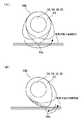
また、図3(A)及び図3(B)は、カム64の2つの駆動モードを示している。カム64の駆動モードには、モータ50A〜50Dを一方向に連続回転させて図3(A)に示すようにカム64を最大リフト位置、すなわちカム64のノーズ64aが吸気弁32側の当接部材と接する位置を越えて正転方向(図3(A)中の矢印方向)に連続的に回転させる正転駆動モードと、正転駆動モードにおける最大リフト位置に達する前にモータ50A〜50Dの回転方向を切り換えて図3(B)に示すようにカム64を往復運動させる揺動駆動モードとがある。   3A and 3B show two drive modes of the cam 64. FIG. In the drive mode of the cam 64, the motors 50A to 50D are continuously rotated in one direction to bring the cam 64 into the maximum lift position, that is, the nose 64a of the cam 64 is in contact with the intake valve 32 side as shown in FIG. The forward drive mode in which the motor 50A to 50D is rotated before reaching the maximum lift position in the forward drive mode, and the forward drive mode for continuously rotating in the forward direction (the arrow direction in FIG. 3A) beyond the position in contact with the member. There is a swing drive mode in which the cam 64 is reciprocated as shown in FIG.

正転駆動モードでは、クランクシャフトの回転に対してカム64の回転速度を可変することで吸気弁32の作用角、リフトタイミングが制御される。また、揺動駆動モードでは、カム64の回転速度とともに、カム64が揺動する角度範囲を制御することで、吸気弁32の最大リフト量、作用角、リフトタイミングを制御することができる。   In the forward rotation drive mode, the operating angle and lift timing of the intake valve 32 are controlled by varying the rotational speed of the cam 64 with respect to the rotation of the crankshaft. In the swing drive mode, the maximum lift amount, the operating angle, and the lift timing of the intake valve 32 can be controlled by controlling the rotational speed of the cam 64 and the angle range in which the cam 64 swings.

これにより、運転状態に応じた最適なリフト量、作用角で吸気弁32を駆動することが可能となる。図4は内燃機関10の機関回転数、出力トルクと、カム64の駆動モードとの関係を示す模式図である。図4に示すように、カム64の駆動モードは、機関回転数と出力トルクとに関連付けて使い分けられる。基本的に低回転域では揺動駆動モードが選択され、高回転域では正転駆動モードが選択される。これにより、低回転域では吸気弁32のリフト量、作用角を少なくし、高回転域では吸気弁32のリフト量、作用角を大きくする制御が行われ、機関回転数と出力トルクに応じた最適な空気量を機関筒内に送ることが可能となる。   As a result, the intake valve 32 can be driven with an optimal lift amount and operating angle according to the operating state. FIG. 4 is a schematic diagram showing the relationship between the engine speed and output torque of the internal combustion engine 10 and the drive mode of the cam 64. As shown in FIG. 4, the drive mode of the cam 64 is selectively used in association with the engine speed and the output torque. Basically, the swing drive mode is selected in the low rotation range, and the normal rotation drive mode is selected in the high rotation range. As a result, control is performed to reduce the lift amount and operating angle of the intake valve 32 in the low rotation range, and increase the lift amount and operating angle of the intake valve 32 in the high rotation range, depending on the engine speed and output torque. It becomes possible to send the optimal amount of air into the engine cylinder.

図5は、カムシャフト60の構成を詳細に示す模式図である。図5に示すように、カムシャフト60はカムシャフト60Aとカムシャフト60Bとから構成されている。カムシャフト60Aは#4気筒の各吸気弁32を駆動する2つのカム64を備えている。また、カムシャフト60Bは#6気筒の各吸気弁32を駆動する2つのカム64を備えている。なお、#3気筒、#5気筒の吸気弁32を駆動するカムシャフト56もカムシャフト60と同様に2つのカムシャフトから構成されている。   FIG. 5 is a schematic diagram showing the configuration of the camshaft 60 in detail. As shown in FIG. 5, the camshaft 60 includes a camshaft 60A and a camshaft 60B. The camshaft 60A includes two cams 64 that drive the intake valves 32 of the # 4 cylinder. The camshaft 60B includes two cams 64 that drive the intake valves 32 of the # 6 cylinder. Similar to the camshaft 60, the camshaft 56 that drives the intake valves 32 of the # 3 and # 5 cylinders is also composed of two camshafts.

カムシャフト60Aには、その端部にフランジ部66が設けられている。同様に、カムシャフト60Bには、その端部にフランジ部68が設けられている。カムシャフト60Aのフランジ部66には、その中心に穴67が設けられている。また、カムシャフト60Bのフランジ部68には、その中心からカムシャフト60Aに向かって突出する軸69が設けられている。カムシャフト60Aとカムシャフト60Bは、穴67に対して軸69が回動可能に嵌合し、フランジ部66とフランジ部68の端面同士が当接することで一体化される。   The cam shaft 60A is provided with a flange portion 66 at the end thereof. Similarly, the camshaft 60B is provided with a flange portion 68 at the end thereof. A hole 67 is provided in the center of the flange portion 66 of the camshaft 60A. In addition, the flange portion 68 of the camshaft 60B is provided with a shaft 69 that protrudes from the center toward the camshaft 60A. The camshaft 60 </ b> A and the camshaft 60 </ b> B are integrated by fitting the shaft 69 into the hole 67 so that the shaft 69 can rotate, and the end faces of the flange portion 66 and the flange portion 68 are in contact with each other.

図6は、フランジ部66,68の端面を示す模式図であって、図6(A)はフランジ部66の端面を、図6(B)はフランジ部68の端面を示している。図5及び図6(A)に示すように、フランジ部66の端面は、基準面66Aと、基準面66Aに対してカムシャフト60B側に突出する突出面66Bを備えている。基準面66Aと突出面66Bとの境界には、段差66Cおよび66Dが設けられている。   6A and 6B are schematic views showing the end faces of the flange portions 66 and 68. FIG. 6A shows the end face of the flange portion 66, and FIG. 6B shows the end face of the flange portion 68. As shown in FIGS. 5 and 6A, the end surface of the flange portion 66 includes a reference surface 66A and a protruding surface 66B that protrudes toward the camshaft 60B with respect to the reference surface 66A. Steps 66C and 66D are provided at the boundary between the reference surface 66A and the protruding surface 66B.

同様に、図5及び図6(B)に示すように、フランジ部68の端面は、基準面68Aと、基準面68Aに対してカムシャフト60A側に突出する突出面68Bを備えている。基準面68Aと突出面68Bとの境界には、段差68Cおよび68Dが設けられている。   Similarly, as shown in FIGS. 5 and 6B, the end surface of the flange portion 68 includes a reference surface 68A and a protruding surface 68B that protrudes toward the camshaft 60A with respect to the reference surface 68A. Steps 68C and 68D are provided at the boundary between the reference surface 68A and the protruding surface 68B.

カムシャフト60Aとカムシャフト60Bが連結された状態では、フランジ部66の基準面66Aとフランジ部68の突出面68Bとが密着し、フランジ部68の基準面68Aとフランジ部66の突出面66Bとが密着する。   In a state where the camshaft 60A and the camshaft 60B are connected, the reference surface 66A of the flange portion 66 and the protruding surface 68B of the flange portion 68 are in close contact, and the reference surface 68A of the flange portion 68 and the protruding surface 66B of the flange portion 66 Is in close contact.

図6(A)に示すように、フランジ部66の基準面66Aには、2つの穴70,72が設けられている。また、図6(B)に示すように、フランジ部68の突出面68Bには、1つのロックピン74が設けられている。ロックピン74は、突出面68Bからカムシャフト60A側に突出するように設けられている。   As shown in FIG. 6A, two holes 70 and 72 are provided in the reference surface 66 </ b> A of the flange portion 66. Further, as shown in FIG. 6B, one lock pin 74 is provided on the projecting surface 68 </ b> B of the flange portion 68. The lock pin 74 is provided so as to protrude from the protruding surface 68B toward the camshaft 60A.

軸69の中心とロックピン74の中心との距離は、穴70又は穴72の中心と穴67の中心との距離と同一である。また、穴70,72に対してロックピン74が嵌合するように、両者の内径、外径が規定されている。従って、穴67に軸69が嵌合している状態では、穴70又は穴72とロックピン74との角度位置が適合することを条件に、穴70又は穴72に対してロックピン74が嵌合することができる。   The distance between the center of the shaft 69 and the center of the lock pin 74 is the same as the distance between the center of the hole 70 or 72 and the center of the hole 67. Further, the inner diameter and the outer diameter of both are defined so that the lock pins 74 are fitted into the holes 70 and 72. Therefore, in a state where the shaft 69 is fitted in the hole 67, the lock pin 74 is fitted to the hole 70 or the hole 72 on condition that the angular position of the hole 70 or the hole 72 and the lock pin 74 is matched. Can be combined.

カムシャフト60Aとカムシャフト60Bを連結した状態において、ロックピン74が穴70又は穴72のいずれにも挿入されていない状態では、カムシャフト60Aとカムシャフト60Bは相対的に回転することができる。そして、ロックピン74が穴70,72のいずれか一方に挿入されると、カムシャフト60Aとカムシャフト60Bの相対的な回転位置が固定される。   In a state where the camshaft 60A and the camshaft 60B are connected, when the lock pin 74 is not inserted into either the hole 70 or the hole 72, the camshaft 60A and the camshaft 60B can rotate relatively. When the lock pin 74 is inserted into one of the holes 70 and 72, the relative rotational positions of the camshaft 60A and the camshaft 60B are fixed.

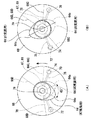
図7は、カムシャフト60Aとカムシャフト60Bを連結した状態において、カムシャフト60Aに設けられたカム64と、カムシャフト60Bに設けられたカム64との位置関係を示す模式図である。ここで、図7は、図5中に示す矢印X方向からカムシャフト60を見た状態を示している。そして、図7(A)は、ロックピン74が穴70に挿入された状態を示しており、図7(B)は、ロックピン74が穴72に挿入された状態を示している。   FIG. 7 is a schematic diagram showing a positional relationship between the cam 64 provided on the camshaft 60A and the cam 64 provided on the camshaft 60B in a state where the camshaft 60A and the camshaft 60B are connected. Here, FIG. 7 shows a state in which the camshaft 60 is viewed from the direction of the arrow X shown in FIG. FIG. 7A shows a state where the lock pin 74 is inserted into the hole 70, and FIG. 7B shows a state where the lock pin 74 is inserted into the hole 72.

図7(A)に示す状態は、正転駆動モードで吸気弁32を開閉駆動する場合に設定される。図7(A)に示すように、ロックピン74が穴70に挿入された状態では、カムシャフト60Aに設けられた#4気筒用のカム64のノーズ64aと、カムシャフト60Bに設けられた#6気筒用のカム64のノーズ60aとの角度位置が、120°だけ離間した位置に設定される。   The state shown in FIG. 7A is set when the intake valve 32 is driven to open and close in the normal rotation drive mode. As shown in FIG. 7A, when the lock pin 74 is inserted into the hole 70, the nose 64a of the # 64 cylinder cam 64 provided on the camshaft 60A and the # provided on the camshaft 60B are provided. The angular position of the six-cylinder cam 64 and the nose 60a is set at a position separated by 120 °.

図7(A)に示すように、ロックピン74が穴70に挿入された状態では、フランジ部66の段差66Cとフランジ部68の段差68Cとが当接している。従って、カムシャフト60Aとカムシャフト60Bの回転位置は、ロックピン74と穴70の係合により規定されるとともに、段差66Cと段差68Cとが当接する方向の相対的な回転に対しては、段差66Cと段差68Cとの当接により規定されている。このように、ロックピン74と穴70との係合と、段差66C及び段差68Cの当接とを併用してカムシャフト60Aとカムシャフト60Bの相対的な回転位置を固定することで、回転位置の固定を確実に行うことができる。   As shown in FIG. 7A, when the lock pin 74 is inserted into the hole 70, the step 66C of the flange portion 66 and the step 68C of the flange portion 68 are in contact with each other. Therefore, the rotational positions of the camshaft 60A and the camshaft 60B are defined by the engagement of the lock pin 74 and the hole 70, and the relative rotation in the direction in which the step 66C and the step 68C are in contact with each other. It is defined by the contact between 66C and the step 68C. Thus, by fixing the relative rotational positions of the camshaft 60A and the camshaft 60B by using the engagement between the lock pin 74 and the hole 70 and the contact of the step 66C and the step 68C together, the rotational position Can be reliably fixed.

V型6気筒の内燃機関10では、クランクシャフトが2回転(=720°)する間に#1→#2→#3→#4→#5→#6の順で爆発行程が行われるため、#4気筒の吸気行程から#6気筒の吸気行程までの間にクランクシャフトは240°回転する。このとき、カムシャフト60の回転数とクランクシャフトの回転数との比が1:2となるように動弁装置36Dのモータ50Dを駆動すると、#4気筒の吸気行程から#6気筒の吸気行程までの間にカムシャフト60は120°回転する。従って、図7(A)に示す矢印方向(反時計回り方向)にカムシャフト60を回転し、#4気筒用のカム64と#6気筒用のカム64との相対的な角度位置を120°だけ離間させておくことで、#4気筒と#6気筒の吸気行程に合わせて、#4気筒と#6気筒の吸気弁32を開閉駆動することができる。そして、正転駆動モードでは、カムシャフト60の回転数とクランクシャフトの回転数との比が1:2となる状態を基準としてカムシャフト60の回転数を変動させることで、吸気弁32がリフトする際の作用角、リフトタイミングを可変することが可能となる。   In the V-type 6-cylinder internal combustion engine 10, the explosion stroke is performed in the order of # 1 → # 2 → # 3 → # 4 → # 5 → # 6 while the crankshaft rotates twice (= 720 °). The crankshaft rotates 240 ° between the intake stroke of the # 4 cylinder and the intake stroke of the # 6 cylinder. At this time, if the motor 50D of the valve gear 36D is driven so that the ratio of the rotation speed of the camshaft 60 and the rotation speed of the crankshaft is 1: 2, the intake stroke of the # 6 cylinder to the intake stroke of the # 6 cylinder is driven. In the meantime, the camshaft 60 rotates 120 °. Accordingly, the camshaft 60 is rotated in the arrow direction (counterclockwise direction) shown in FIG. 7A, and the relative angular position between the cam 64 for the # 4 cylinder and the cam 64 for the # 6 cylinder is 120 °. By separating them only, the intake valves 32 of the # 4 and # 6 cylinders can be driven to open and close in accordance with the intake strokes of the # 4 and # 6 cylinders. In the normal rotation drive mode, the intake valve 32 is lifted by changing the rotational speed of the camshaft 60 with reference to the state where the ratio of the rotational speed of the camshaft 60 to the rotational speed of the crankshaft is 1: 2. It is possible to vary the working angle and lift timing when performing the operation.

一方、図7(A)に示す状態で揺動駆動モードを行う場合は、図28で説明したように、一方の気筒の吸気弁32を駆動した後、カムシャフト60を大きく回転させる必要があり、モータの消費電力が増大してしまう。   On the other hand, when the swing drive mode is performed in the state shown in FIG. 7A, the camshaft 60 needs to be largely rotated after driving the intake valve 32 of one cylinder, as described in FIG. The power consumption of the motor will increase.

このため、本実施形態では、揺動駆動モードで吸気弁32を開閉駆動する場合は、図7(A)の状態からカムシャフト60Aとカムシャフト60Bの相対的な角度位置を可変し、図7(B)に示すように、カムシャフト60Aに設けられた#4気筒用のカム64のノーズ64aと、カムシャフト60Bに設けられた#6気筒用のカム64のノーズ60aとの角度位置が180°だけ離間するように両者の位置を規定する。   Therefore, in the present embodiment, when the intake valve 32 is driven to open and close in the swing drive mode, the relative angular positions of the camshaft 60A and the camshaft 60B are varied from the state shown in FIG. As shown in (B), the angular position of the nose 64a of the # 64 cylinder cam 64 provided on the camshaft 60A and the nose 60a of the # 6 cylinder cam 64 provided on the camshaft 60B is 180. The positions of both are defined so as to be separated by °.

これにより、揺動駆動モードにおいて、#4気筒、#6気筒の一方の気筒の吸気弁32を駆動した後、他方の気筒の吸気弁32を駆動する際のカムシャフト60の回転量を図28の場合と比べて低減することが可能となる。より具体的には、#4気筒用のカム64のノーズ64aと、カムシャフト60Bに設けられた#6気筒用のカム64のノーズ60aとの角度位置を180°に設定したことで、図28の場合と比べるとカムシャフト60の回転量を60°程度低減することが可能である。従って、揺動駆動モードで吸気弁32を駆動する際に、モータ50Dの消費電力を大幅に低減することができる。   Thus, in the swing drive mode, after the intake valve 32 of one of the # 4 and # 6 cylinders is driven, the rotation amount of the camshaft 60 when the intake valve 32 of the other cylinder is driven is shown in FIG. This can be reduced compared to the case of. More specifically, the angular position between the nose 64a of the cam 64 for the # 4 cylinder and the nose 60a of the cam 64 for the # 6 cylinder provided on the camshaft 60B is set to 180 °. Compared with the case, the rotation amount of the camshaft 60 can be reduced by about 60 °. Therefore, when driving the intake valve 32 in the swing drive mode, the power consumption of the motor 50D can be greatly reduced.

なお、図7(B)に示す状態では、ロックピン74が穴72に挿入され、フランジ部66の段差66Dとフランジ部68の段差68Dとが当接している。従って、カムシャフト60Aとカムシャフト60Bの回転位置は、ロックピン74と穴72の係合により規定されるとともに、段差66Dと段差68Dとが当接する方向の相対的な回転に対しては、段差66Dと段差68Dとの当接により規定されている。   7B, the lock pin 74 is inserted into the hole 72, and the step 66D of the flange portion 66 and the step 68D of the flange portion 68 are in contact with each other. Accordingly, the rotational positions of the camshaft 60A and the camshaft 60B are defined by the engagement of the lock pin 74 and the hole 72, and the relative difference in the direction in which the step 66D and the step 68D come into contact with each other. It is defined by the contact between 66D and the step 68D.

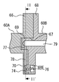
次に、ロックピン74と穴70,72との係合を切り換える機構について説明する。図8は、図7(A)中の一点鎖線I−I’に沿った断面を示す模式図であって、カムシャフト60Aとカムシャフト60Bとの連結部の近傍を示している。図8に示すように、フランジ部66に設けられた穴67とフランジ部68に設けられた軸69は回動可能に嵌合している。   Next, a mechanism for switching the engagement between the lock pin 74 and the holes 70 and 72 will be described. FIG. 8 is a schematic diagram showing a cross section taken along the alternate long and short dash line I-I ′ in FIG. 7A, and shows the vicinity of the connecting portion between the camshaft 60 </ b> A and the camshaft 60 </ b> B. As shown in FIG. 8, a hole 67 provided in the flange portion 66 and a shaft 69 provided in the flange portion 68 are fitted so as to be rotatable.

図8に示すように、ロックピン74はフランジ部68に設けられた収納穴68Eに挿入されている。ロックピン74と収納穴68Eの底との間には、圧縮バネ76が挿入されている。   As shown in FIG. 8, the lock pin 74 is inserted into a storage hole 68 </ b> E provided in the flange portion 68. A compression spring 76 is inserted between the lock pin 74 and the bottom of the storage hole 68E.

フランジ部66に設けられた穴70,72には、オイル通路78が接続されている。図6及び図7に示すように、オイル通路78は穴67から穴70、穴72のそれぞれに向けて放射状に延在している。   An oil passage 78 is connected to the holes 70 and 72 provided in the flange portion 66. As shown in FIGS. 6 and 7, the oil passage 78 extends radially from the hole 67 toward each of the hole 70 and the hole 72.

図8に示すように、カムシャフト60Bには、回転の中心軸に沿ってオイル通路79が設けられており、オイル通路79の端部には、軸69の外周に向けてオイル通路77が設けられている。カムシャフト60Aとカムシャフト60Bが連結された状態では、オイル通路77とオイル通路78のスラスト方向の位置は一致しており、オイル通路77は2つのオイル通路78と接続されている。   As shown in FIG. 8, the camshaft 60 </ b> B is provided with an oil passage 79 along the central axis of rotation, and an oil passage 77 is provided at the end of the oil passage 79 toward the outer periphery of the shaft 69. It has been. In the state where the camshaft 60 </ b> A and the camshaft 60 </ b> B are coupled, the positions of the oil passage 77 and the oil passage 78 in the thrust direction coincide with each other, and the oil passage 77 is connected to the two oil passages 78.

オイル通路79には、オイルポンプにより所定の圧力でオイルが供給される。オイル通路79に供給されたオイルは、オイル通路77、オイル通路78を通って穴70、穴72に供給される。   Oil is supplied to the oil passage 79 at a predetermined pressure by an oil pump. The oil supplied to the oil passage 79 is supplied to the hole 70 and the hole 72 through the oil passage 77 and the oil passage 78.

図8は、オイルによる油圧がかけられていない状態を示している。この状態では、圧縮バネ76の押圧力により、ロックピン74がフランジ部66の穴70に挿入される。これにより、カムシャフト60Aとカムシャフト60Bの相対的な回転位置が図7(A)に示す状態に設定される。   FIG. 8 shows a state in which no oil pressure is applied. In this state, the lock pin 74 is inserted into the hole 70 of the flange portion 66 by the pressing force of the compression spring 76. Thereby, the relative rotational positions of the camshaft 60A and the camshaft 60B are set to the state shown in FIG.

図9は、オイル通路79、オイル通路77、オイル通路78を経由して穴70にオイルを供給し、油圧をかけた状態を示している。この場合、穴70内にオイルが充満し、油圧によりロックピン74が収納穴68Eに収納される。ロックピン74が収納穴68E内に収納された状態では、ロックピン74の上面はフランジ部68の突出面68Bよりも凹面となる。従って、ロックピン74と穴70または穴72との係合が外れ、カムシャフト60Aとカムシャフト60Bを相対的に回転させることが可能となる。   FIG. 9 shows a state in which oil is supplied to the hole 70 via the oil passage 79, the oil passage 77, and the oil passage 78 to apply hydraulic pressure. In this case, the hole 70 is filled with oil, and the lock pin 74 is stored in the storage hole 68E by hydraulic pressure. In a state where the lock pin 74 is stored in the storage hole 68E, the upper surface of the lock pin 74 is more concave than the protruding surface 68B of the flange portion 68. Therefore, the lock pin 74 is disengaged from the hole 70 or the hole 72, and the camshaft 60A and the camshaft 60B can be relatively rotated.

図10は、図8中の一点鎖線II−II’に沿った位置の断面を示す模式図である。ここで、図10(A)は図7(A)の状態に対応しており、図10(B)は図7(B)の状態に対応している。すなわち、図10(A)ではロックピン74が穴70に挿入されており、図10(B)ではロックピン74が穴72に挿入されている。   FIG. 10 is a schematic diagram showing a cross section at a position along the alternate long and short dash line II-II ′ in FIG. 8. Here, FIG. 10 (A) corresponds to the state of FIG. 7 (A), and FIG. 10 (B) corresponds to the state of FIG. 7 (B). That is, in FIG. 10A, the lock pin 74 is inserted into the hole 70, and in FIG. 10B, the lock pin 74 is inserted into the hole 72.

図10に示すように、オイル通路77は、図10(A)に示す状態と図10(B)に示す状態との間でカムシャフト60A,60Bの相対的な角度位置が変化した場合であっても、オイル通路79と2つのオイル通路78が常に接続されるように、所定の角度範囲で扇状に連続して設けられている。より詳細には、オイル通路77は2つのオイル通路78がなす角度(=60°)とカムシャフト60A,60Bの相対的な回転角度(=60°)とを合計した角度(=120°)よりも広い範囲に設けられている。従って、オイル通路79内のオイルに油圧をかけると、穴70および穴72の双方にオイルが供給される。これにり、穴70又は穴72に挿入されたロックピン74を駆動することが可能である。   As shown in FIG. 10, the oil passage 77 is a case where the relative angular positions of the camshafts 60A and 60B change between the state shown in FIG. 10A and the state shown in FIG. However, the oil passage 79 and the two oil passages 78 are continuously provided in a fan shape within a predetermined angle range so that they are always connected. More specifically, the oil passage 77 is based on an angle (= 120 °) that is a sum of an angle (= 60 °) formed by the two oil passages 78 and a relative rotation angle (= 60 °) of the camshafts 60A and 60B. Is also provided in a wide range. Therefore, when oil pressure is applied to the oil in the oil passage 79, the oil is supplied to both the hole 70 and the hole 72. In this way, it is possible to drive the lock pin 74 inserted into the hole 70 or the hole 72.

図7(A)及び図7(B)に示すように、カムシャフト60Aとカムシャフト60Bの回転位置が可変した場合であっても、フランジ部66に設けられた2つの穴70,72上には常にフランジ部68の突出面68Bが位置している。そして、フランジ部66の基準面66Aとフランジ部68の突出面68Bとは密着しているため、穴70,72は突出面68Bにより常に塞がれている状態となる。   As shown in FIGS. 7A and 7B, even when the rotational positions of the camshaft 60A and the camshaft 60B are varied, the two holes 70 and 72 provided in the flange portion 66 are formed. The protrusion surface 68B of the flange portion 68 is always located. Since the reference surface 66A of the flange portion 66 and the protruding surface 68B of the flange portion 68 are in close contact with each other, the holes 70 and 72 are always closed by the protruding surface 68B.

従って、ロックピン74を外す際に油圧をかけると、穴70と穴72の双方にオイルが供給されるが、ロックピン74が係合していない穴から外部にオイルが流出してしまうことはない。これにより、ロックピン74の係合を外す際に、オイルの流出による油圧低下を確実に抑止できる。   Therefore, if hydraulic pressure is applied when the lock pin 74 is removed, oil is supplied to both the hole 70 and the hole 72, but the oil will flow out from the hole where the lock pin 74 is not engaged. Absent. Thereby, when the lock pin 74 is disengaged, a decrease in hydraulic pressure due to the outflow of oil can be reliably prevented.

次に、穴70,72とロックピン74との係合を外すタイミングについて説明する。先ず、正転駆動モードから揺動駆動モードへ切り換える場合について説明する。図2に示すように、カムシャフト60を駆動するためのカム駆動ギヤ62は、カムシャフト60Bに設けられている。正転駆動モードでは、ロックピン74と穴70とが係合し、段差66Cと段差68Cが当接することにより、カムシャフト60Bの回転がカムシャフト60Aに伝達され、図7(A)に示す矢印方向(反時計回り方向)にカムシャフト60A及びカムシャフト60Bが回転する。   Next, the timing for releasing the engagement between the holes 70 and 72 and the lock pin 74 will be described. First, the case of switching from the forward drive mode to the swing drive mode will be described. As shown in FIG. 2, a cam drive gear 62 for driving the camshaft 60 is provided on the camshaft 60B. In the forward rotation drive mode, the lock pin 74 and the hole 70 are engaged, and the step 66C and the step 68C come into contact with each other, whereby the rotation of the camshaft 60B is transmitted to the camshaft 60A, and the arrow shown in FIG. The camshaft 60A and the camshaft 60B rotate in the direction (counterclockwise direction).

揺動駆動モードに切り換える際には、モータ50Dの出力軸の回転方向を反転させるとともに、オイル通路79内のオイルに油圧がかけられる。これにより、穴70にオイルが送られ、油圧によりロックピン74が収納穴68Eに収納される。   When switching to the swing drive mode, the rotation direction of the output shaft of the motor 50D is reversed and hydraulic pressure is applied to the oil in the oil passage 79. Thereby, oil is sent to the hole 70, and the lock pin 74 is stored in the storage hole 68E by hydraulic pressure.

ロックピン74が収納穴68Eに収納されると、カムシャフト60Bはカムシャフト60Aに対して相対的に回転することができる。ここで、モータ50Dの出力軸の回転方向が反転されており、出力軸の回転はカム駆動ギヤ62を介してカムシャフト60Bに伝達されるため、モータ50Dの反転駆動により、カムシャフト60Bはカムシャフト60Aに対して図7(A)中において時計回り方向に回転する。なお、カムシャフト60Aに設けられたカム64には#4気筒の吸気弁32のバルブスプリング反力が作用しており、カムシャフト60Aの回転方向には摺動抵抗が生じている。従って、ロックピン74と穴70との係合を外してモータ50Dを反転させた際に、カムシャフト60Aがカムシャフト60Bとともに同じ方向に回転してしまうことはない。   When the lock pin 74 is stored in the storage hole 68E, the camshaft 60B can rotate relative to the camshaft 60A. Here, since the rotation direction of the output shaft of the motor 50D is reversed and the rotation of the output shaft is transmitted to the camshaft 60B via the cam drive gear 62, the camshaft 60B is camped by the reversal drive of the motor 50D. It rotates clockwise in FIG. 7A with respect to the shaft 60A. Note that the valve spring reaction force of the intake valve 32 of the # 4 cylinder acts on the cam 64 provided on the camshaft 60A, and sliding resistance is generated in the rotation direction of the camshaft 60A. Therefore, when the engagement between the lock pin 74 and the hole 70 is released and the motor 50D is reversed, the camshaft 60A does not rotate in the same direction as the camshaft 60B.

カムシャフト60Bがカムシャフト60Aに対して相対的に回転し始めると、オイル通路79へかけられていた油圧が解除される。そして、カムシャフト60Aに対するカムシャフト60Bの相対的な回転に伴って、段差66Dと段差68Dとの距離が近接していき、やがて段差66Dと段差68Dとが当接する。これにより、穴72とロックピン74の位置が適合し、既に油圧が解除されているため、圧縮バネ76の付勢力によりロックピン74が穴72に挿入される。これにより、カムシャフト60Aとカムシャフト60Bとの相対的な角度位置が図7(B)に示す状態に設定され、揺動駆動モードによりカムシャフト60を駆動することができる。   When the camshaft 60B starts to rotate relative to the camshaft 60A, the hydraulic pressure applied to the oil passage 79 is released. As the camshaft 60B rotates relative to the camshaft 60A, the distance between the step 66D and the step 68D becomes closer, and the step 66D and the step 68D come into contact with each other. As a result, the positions of the hole 72 and the lock pin 74 are matched and the hydraulic pressure has already been released, so that the lock pin 74 is inserted into the hole 72 by the urging force of the compression spring 76. Accordingly, the relative angular position between the camshaft 60A and the camshaft 60B is set to the state shown in FIG. 7B, and the camshaft 60 can be driven in the swing drive mode.

次に、揺動駆動モードから正転駆動モードへ切り換える場合について説明する。正転駆動モードに切り換える際には、図7(B)においてカムシャフト60Bが反時計回りに回転する方向にモータ50Dが駆動される。そして、この状態でオイル通路79内のオイルに油圧がかけられる。これにより、穴72にオイルが送られ、油圧によりロックピン74が収納穴68Eに収納される。   Next, a case where the swing drive mode is switched to the forward rotation drive mode will be described. When switching to the forward rotation drive mode, the motor 50D is driven in a direction in which the camshaft 60B rotates counterclockwise in FIG. 7B. In this state, hydraulic pressure is applied to the oil in the oil passage 79. Thereby, oil is sent to the hole 72, and the lock pin 74 is stored in the storage hole 68E by hydraulic pressure.

ロックピン74が収納穴68Eに収納されると、カムシャフト60Bとカムシャフト60Aの回転方向の係合が外れる。そして、モータ50Dの駆動力を受けたカムシャフト60Bはカムシャフト60Aに対して図7(B)中において反時計回りに回転する。この場合においても、カムシャフト60Aの回転方向にはバルブスプリング反力による摺動抵抗が作用しているため、カムシャフト60Aがカムシャフト60Bともに同じ方向に回転してしまうことはない。   When the lock pin 74 is stored in the storage hole 68E, the camshaft 60B and the camshaft 60A are disengaged in the rotational direction. The camshaft 60B that receives the driving force of the motor 50D rotates counterclockwise in FIG. 7B with respect to the camshaft 60A. Also in this case, since the sliding resistance due to the reaction force of the valve spring acts in the rotation direction of the camshaft 60A, the camshaft 60A does not rotate in the same direction together with the camshaft 60B.

カムシャフト60Bがカムシャフト60Aに対して相対的に回転し始めると、オイル通路79へかけられていた油圧が解除される。そして、カムシャフト60Aに対するカムシャフト60Bの相対的な回転に伴って、段差66Cと段差68Cとの距離が近接していき、やがて段差66Cと段差68Cとが当接する。これにより、穴70とロックピン74の位置が適合し、既に油圧が解除されているため、圧縮バネ76の付勢力によりロックピン74が穴70に挿入される。これにより、カムシャフト60Aとカムシャフト60Bとの相対的な角度位置が図7(A)に示す状態に設定され、正転駆動モードによりカムシャフト60を駆動することができる。   When the camshaft 60B starts to rotate relative to the camshaft 60A, the hydraulic pressure applied to the oil passage 79 is released. As the camshaft 60B rotates relative to the camshaft 60A, the distance between the step 66C and the step 68C becomes closer, and the step 66C and the step 68C come into contact with each other. As a result, the positions of the hole 70 and the lock pin 74 are matched and the hydraulic pressure has already been released, so that the lock pin 74 is inserted into the hole 70 by the urging force of the compression spring 76. Accordingly, the relative angular position between the camshaft 60A and the camshaft 60B is set to the state shown in FIG. 7A, and the camshaft 60 can be driven in the normal rotation drive mode.

なお、カムシャフト56においても同様に、揺動駆動モードで吸気弁32を駆動する場合は、正転駆動モードに対してカム64の相対的な位置が可変される。カムシャフト56には#3気筒用のカム64と#5気筒用のカム64が設けられており、#3気筒の吸気行程から#5気筒の吸気行程までの間にクランクシャフトは240°回転する。従って、カムシャフト56の回転数とクランクシャフトの回転数との比を1:2とした場合、#3気筒の吸気行程から#5気筒の吸気行程までの間にカムシャフト56は120°回転する。従って、正転駆動モード時は、#3気筒用のカム64と#5気筒用のカム64との相対的な角度位置を120°だけ離間させておくことで、#3気筒と#5気筒の吸気行程に合わせて吸気弁32を開閉駆動することができる。また、揺動駆動モード時には、#3気筒用のカム64と#5気筒用のカム64が180°だけ離間するようにカムシャフト56を構成する2つのカムシャフトの相対的な角度位置を可変することで、揺動駆動モード時のカムシャフト56の回転量を最小限に抑えることができる。   Similarly, in the camshaft 56, when the intake valve 32 is driven in the swing drive mode, the relative position of the cam 64 is varied with respect to the normal rotation drive mode. The camshaft 56 is provided with a cam 64 for the # 3 cylinder and a cam 64 for the # 5 cylinder. The crankshaft rotates by 240 ° between the intake stroke of the # 3 cylinder and the intake stroke of the # 5 cylinder. . Accordingly, when the ratio of the rotational speed of the camshaft 56 to the rotational speed of the crankshaft is 1: 2, the camshaft 56 rotates 120 ° between the intake stroke of the # 3 cylinder and the intake stroke of the # 5 cylinder. . Therefore, in the forward rotation drive mode, the relative angular positions of the cam 64 for the # 3 cylinder and the cam 64 for the # 5 cylinder are separated from each other by 120 °, so that the # 3 cylinder and the # 5 cylinder The intake valve 32 can be driven to open and close in accordance with the intake stroke. In the swing drive mode, the relative angular positions of the two camshafts constituting the camshaft 56 are varied so that the # 3 cylinder cam 64 and the # 5 cylinder cam 64 are separated by 180 °. As a result, the amount of rotation of the camshaft 56 in the swing drive mode can be minimized.

以上説明したように実施の形態1によれば、V型6気筒で構成される内燃機関10において、2つの気筒の吸気弁32を1つのカムシャフト60で駆動する際に、揺動駆動モードで吸気弁32を駆動する場合は、正転駆動モードに対してカム64の相対的な位置を可変するようにしたため、揺動駆動モード時のカムシャフト60の回転量を低減することが可能となる。これにより、カムシャフト60を駆動するモータ50Dの消費電力を低減することができ、システム効率を高めることが可能となる。   As described above, according to the first embodiment, when the intake valve 32 of two cylinders is driven by one camshaft 60 in the internal combustion engine 10 configured by V-type six cylinders, the swing drive mode is used. When the intake valve 32 is driven, the relative position of the cam 64 is varied with respect to the normal rotation drive mode, so that the amount of rotation of the camshaft 60 in the swing drive mode can be reduced. . Thereby, the power consumption of the motor 50D that drives the camshaft 60 can be reduced, and the system efficiency can be increased.

実施の形態2.
次に、本発明の実施の形態2について説明する。実施の形態2は、8気筒の内燃機関10に本発明を適用したものである。図11は、実施の形態2の動弁装置36、動弁装置38の周辺の構成を示す模式図であって、主としてシリンダヘッド周りの構成を示している。本実施形態の内燃機関10はV型の8気筒で構成され、#2、#4、#6、#8の4気筒が一方のバンク80に配置され、#1、#3、#5、#7の4気筒が他方のバンク82に配置されている。
Embodiment 2. FIG.
Next, a second embodiment of the present invention will be described. In the second embodiment, the present invention is applied to an 8-cylinder internal combustion engine 10. FIG. 11 is a schematic diagram showing the configuration around the valve operating device 36 and the valve operating device 38 of the second embodiment, and mainly shows the configuration around the cylinder head. The internal combustion engine 10 of the present embodiment is configured by eight V-type cylinders, and four cylinders # 2, # 4, # 6, and # 8 are arranged in one bank 80, and # 1, # 3, # 5, # Seven four cylinders are arranged in the other bank 82.

バンク80、バンク82は、吸気弁32を駆動する動弁装置36、排気弁34を駆動する動弁装置38をそれぞれ備えている。ここでは、動弁装置36の構成を中心に説明するが、動弁装置36と動弁装置38は基本的に同一の構成を有している。実施の形態1と同様に、内燃機関10の個々の気筒に2つの吸気弁32と2つの排気弁34とが備わっているものとする。   The bank 80 and the bank 82 respectively include a valve operating device 36 that drives the intake valve 32 and a valve operating device 38 that drives the exhaust valve 34. Here, the configuration of the valve operating device 36 will be mainly described. However, the valve operating device 36 and the valve operating device 38 basically have the same configuration. As in the first embodiment, it is assumed that each cylinder of the internal combustion engine 10 is provided with two intake valves 32 and two exhaust valves 34.

バンク80に配置された動弁装置36は、2つの装置(動弁装置36E、動弁装置36F)から構成されている。また、バンク82に配置された動弁装置36は、2つの装置(動弁装置36G、動弁装置36H)から構成されている。動弁装置36Eは#2気筒および#4気筒が備える吸気弁32を駆動し、動弁装置36Fは#6気筒および#8気筒が備える吸気弁32を駆動する。また、動弁装置36Gは#1気筒および#3気筒が備える吸気弁32を駆動し、動弁装置36Hは#5気筒および#7気筒が備える吸気弁32を駆動する。   The valve gear 36 arranged in the bank 80 includes two devices (the valve gear 36E and the valve gear 36F). In addition, the valve gear 36 disposed in the bank 82 includes two devices (the valve gear 36G and the valve gear 36H). The valve gear 36E drives the intake valve 32 provided in the # 2 cylinder and the # 4 cylinder, and the valve drive device 36F drives the intake valve 32 provided in the # 6 cylinder and the # 8 cylinder. Further, the valve gear 36G drives the intake valve 32 provided in the # 1 cylinder and the # 3 cylinder, and the valve drive device 36H drives the intake valve 32 provided in the # 5 cylinder and the # 7 cylinder.

実施の形態1と同様に、動弁装置36E,36F,36G,36Hのそれぞれは、駆動源としてのモータ50E,50F,50G,50Hを備えている。バンク80において、モータ50Eの回転運動はギヤ列52Eを介してカムシャフト84に伝達される。同様に、モータ50Fの回転運動はギヤ列52Fを介してカムシャフト86に伝達される。   As in the first embodiment, each of the valve gears 36E, 36F, 36G, and 36H includes motors 50E, 50F, 50G, and 50H as drive sources. In the bank 80, the rotational motion of the motor 50E is transmitted to the camshaft 84 via the gear train 52E. Similarly, the rotational motion of the motor 50F is transmitted to the camshaft 86 via the gear train 52F.

バンク82においても同様に、モータ50Gの回転運動はギヤ列52Gを介してカムシャフト88に伝達される。同様に、モータ50Hの回転運動はギヤ列52Hを介してカムシャフト90に伝達される。   Similarly, in the bank 82, the rotational motion of the motor 50G is transmitted to the camshaft 88 via the gear train 52G. Similarly, the rotational motion of the motor 50H is transmitted to the camshaft 90 via the gear train 52H.

バンク80において、カムシャフト84は#2,#4気筒の吸気弁32の上部に配置されており、カムシャフト84に設けられた4つのカム64により#2,#4気筒の各吸気弁32が開閉駆動される。また、カムシャフト86は#6,#8気筒の吸気弁32の上部に配置されており、カムシャフト86に設けられた4つのカム64により#6,#8気筒の各吸気弁32が開閉駆動される。   In the bank 80, the camshaft 84 is disposed above the intake valves 32 of the # 2 and # 4 cylinders, and the intake valves 32 of the # 2 and # 4 cylinders are connected by four cams 64 provided on the camshaft 84. It is opened and closed. The camshaft 86 is disposed above the intake valves 32 of the # 6 and # 8 cylinders. The four cams 64 provided on the camshaft 86 open and close the intake valves 32 of the # 6 and # 8 cylinders. Is done.

また、バンク82において、カムシャフト88は#1,#3気筒の吸気弁32の上部に配置されており、カムシャフト88に設けられた4つのカム64により#1,#3気筒の各吸気弁32が開閉駆動される。また、カムシャフト90は#5,#7気筒の吸気弁32の上部に配置されており、カムシャフト90に設けられた4つのカム64により#5,#7気筒の各吸気弁36が開閉駆動される。   In the bank 82, the camshaft 88 is disposed above the intake valves 32 of the # 1 and # 3 cylinders, and the intake valves 32 of the # 1 and # 3 cylinders are provided by four cams 64 provided on the camshaft 88. 32 is driven to open and close. The camshaft 90 is disposed above the intake valves 32 of the # 5 and # 7 cylinders. The four cams 64 provided on the camshaft 90 open and close the intake valves 36 of the # 5 and # 7 cylinders. Is done.

このように構成された本実施形態のシステムにおいても、正転駆動モードまたは揺動駆動モードにより各気筒の吸気弁32が駆動される。従って、実施の形態1と同様に、各気筒の吸気弁32のリフト量、作用角を自在に可変することが可能である。   Also in the system of the present embodiment configured as described above, the intake valve 32 of each cylinder is driven in the normal rotation drive mode or the swing drive mode. Therefore, as in the first embodiment, the lift amount and operating angle of the intake valve 32 of each cylinder can be freely varied.

図12は、カムシャフト90の構成を詳細に示す模式図である。図11に示すように、カムシャフト90はカムシャフト90Aとカムシャフト90Bとから構成されている。カムシャフト90Aは#5気筒の各吸気弁32を駆動する2つのカム64を備えている。また、カムシャフト90Bは#7気筒の各吸気弁32を駆動する2つのカム64を備えている。なお、カムシャフト84、カムシャフト86、カムシャフト88のそれぞれも、カムシャフト90と同様に2つのカムシャフトから構成されている。   FIG. 12 is a schematic diagram showing the configuration of the camshaft 90 in detail. As shown in FIG. 11, the camshaft 90 includes a camshaft 90A and a camshaft 90B. The camshaft 90A includes two cams 64 that drive the intake valves 32 of the # 5 cylinder. The camshaft 90B includes two cams 64 that drive the intake valves 32 of the # 7 cylinder. Each of the camshaft 84, the camshaft 86, and the camshaft 88 is composed of two camshafts similarly to the camshaft 90.

実施の形態1のカムシャフト60と同様に、カムシャフト90Aには、その端部にフランジ部66が設けられている。同様に、カムシャフト90Bには、その端部にフランジ部68が設けられている。カムシャフト90Aのフランジ部66には、その中心に穴67が設けられている。また、カムシャフト90Bのフランジ部68には、その中心からカムシャフト90Aに向かって突出する軸69が設けられている。カムシャフト90Aとカムシャフト90Bは、穴67に対して軸69が回動可能に嵌合し、フランジ部66とフランジ部68の端面同士が当接することで一体化される。   Similar to the camshaft 60 of the first embodiment, the camshaft 90A is provided with a flange portion 66 at the end thereof. Similarly, the camshaft 90B is provided with a flange portion 68 at the end thereof. A hole 67 is provided in the center of the flange portion 66 of the camshaft 90A. In addition, the flange portion 68 of the camshaft 90B is provided with a shaft 69 protruding from the center toward the camshaft 90A. The camshaft 90 </ b> A and the camshaft 90 </ b> B are integrated by fitting the shaft 69 into the hole 67 so that the shaft 69 can rotate, and the end faces of the flange portion 66 and the flange portion 68 are in contact with each other.

図13は、カムシャフト90A,90Bに設けられたフランジ部66,68の端面を示す模式図である。ここで、図13(A)はカムシャフト90Aに設けられたフランジ部66の端面を、図13(B)はカムシャフト90Bに設けられたフランジ部68の端面を示している。   FIG. 13 is a schematic diagram showing end surfaces of flange portions 66 and 68 provided on the camshafts 90A and 90B. Here, FIG. 13A shows an end face of the flange portion 66 provided on the camshaft 90A, and FIG. 13B shows an end face of the flange portion 68 provided on the camshaft 90B.

フランジ部66,68の端面の構成は図6で説明した実施の形態1の構成と同様である。すなわち、フランジ部66は、基準面66Aと突出面66Bを備えており、基準面66Aと突出面66Bとの境界には、段差66Cおよび66Dが設けられている。同様に、フランジ部68は、基準面68Aと突出面68Bを備えており、基準面68Aと突出面68Bとの境界には、段差68Cおよび68Dが設けられている。そして、フランジ部66の基準面66Aには、2つの穴70,72が設けられている。また、図13(B)に示すように、フランジ部68の突出面68Bには、1つのロックピン74が設けられている。ロックピン74は、突出面68Bからカムシャフト90A側に突出するように設けられている。   The configuration of the end faces of the flange portions 66 and 68 is the same as the configuration of the first embodiment described with reference to FIG. That is, the flange portion 66 includes a reference surface 66A and a protruding surface 66B, and steps 66C and 66D are provided at the boundary between the reference surface 66A and the protruding surface 66B. Similarly, the flange portion 68 includes a reference surface 68A and a protruding surface 68B, and steps 68C and 68D are provided at the boundary between the reference surface 68A and the protruding surface 68B. Two holes 70 and 72 are provided in the reference surface 66 </ b> A of the flange portion 66. Further, as shown in FIG. 13B, one lock pin 74 is provided on the projecting surface 68 </ b> B of the flange portion 68. The lock pin 74 is provided so as to protrude from the protruding surface 68B toward the camshaft 90A.

実施の形態1と同様に、カムシャフト90Aとカムシャフト90Bを連結した状態において、ロックピン74が穴70又は穴72のいずれにも挿入されていない状態では、カムシャフト90Aとカムシャフト90Bは相対的に回転することができる。そして、ロックピン74が穴70,72のいずれか一方に挿入されると、カムシャフト90Aとカムシャフト90Bの相対的な回転位置が固定される。   As in the first embodiment, in the state where the camshaft 90A and the camshaft 90B are connected, when the lock pin 74 is not inserted into either the hole 70 or the hole 72, the camshaft 90A and the camshaft 90B are relative to each other. Can be rotated. When the lock pin 74 is inserted into one of the holes 70 and 72, the relative rotational positions of the camshaft 90A and the camshaft 90B are fixed.

図14は、カムシャフト90Aとカムシャフト90Bを連結した状態において、カムシャフト90Aに設けられたカム64と、カムシャフト90Bに設けられたカム64との位置関係を示す模式図である。ここで、図14は、図12中に示す矢印X方向からカムシャフト90を見た状態を示している。そして、図14(A)は、ロックピン74が穴70に挿入された状態を示しており、図14(B)は、ロックピン74が穴72に挿入された状態を示している。   FIG. 14 is a schematic diagram showing a positional relationship between the cam 64 provided on the camshaft 90A and the cam 64 provided on the camshaft 90B in a state where the camshaft 90A and the camshaft 90B are connected. Here, FIG. 14 shows a state in which the camshaft 90 is viewed from the direction of the arrow X shown in FIG. 14A shows a state where the lock pin 74 is inserted into the hole 70, and FIG. 14B shows a state where the lock pin 74 is inserted into the hole 72.

図14(A)に示す状態は、正転駆動モードで吸気弁32を開閉駆動する場合に設定される。図14(A)に示すように、ロックピン74が穴70に挿入された状態では、カムシャフト90Aに設けられた#5気筒用のカム64のノーズ64aと、カムシャフト90Bに設けられた#7気筒用のカム64のノーズ60aとの角度位置が、45°だけ離間した位置に設定される。   The state shown in FIG. 14A is set when the intake valve 32 is driven to open and close in the normal rotation drive mode. As shown in FIG. 14A, when the lock pin 74 is inserted into the hole 70, the nose 64a of the cam 64 for the # 5 cylinder provided on the camshaft 90A and the # provided on the camshaft 90B are provided. The angular position of the seven-cylinder cam 64 and the nose 60a is set at a position separated by 45 °.

図14(A)に示すように、ロックピン74が穴70に挿入された状態では、フランジ部66の段差66Cとフランジ部68の段差68Cとが当接している。従って、カムシャフト90Aとカムシャフト90Bの回転位置は、ロックピン74と穴70の係合により規定されるとともに、段差66Cと段差68Cとが当接する方向の相対的な回転に対しては、段差66Cと段差68Cとの当接により規定されている。   As shown in FIG. 14A, when the lock pin 74 is inserted into the hole 70, the step 66C of the flange portion 66 and the step 68C of the flange portion 68 are in contact with each other. Accordingly, the rotational positions of the camshaft 90A and the camshaft 90B are defined by the engagement of the lock pin 74 and the hole 70, and the relative rotation in the direction in which the step 66C and the step 68C abut against each other. It is defined by the contact between 66C and the step 68C.

V型8気筒の内燃機関10では、クランクシャフトが2回転(=720°)する間に#1→#8→#4→#3→#6→#5→#7→#2の順で爆発行程が行われるため、#5気筒の吸気行程から#7気筒の吸気行程までの間にクランクシャフトは90°回転する。このとき、カムシャフト90の回転数とクランクシャフトの回転数との比が1:2となるように動弁装置36Hのモータ50Hを駆動すると、#5気筒の吸気行程から#7気筒の吸気行程までの間にカムシャフト90は45°回転する。従って、図14(A)に示す矢印方向(反時計回り方向)にカムシャフト90を回転し、#5気筒用のカム64と#7気筒用のカム64との相対的な角度位置を45°だけ離間させておくことで、#5気筒と#7気筒の吸気行程に合わせて、#5気筒と#7気筒の吸気弁32を開閉駆動することができる。   In the V-type 8-cylinder internal combustion engine 10, explosion occurs in the order of # 1 → # 8 → # 4 → # 3 → # 6 → # 5 → # 7 → # 2 while the crankshaft rotates twice (= 720 °). Since the stroke is performed, the crankshaft rotates 90 ° between the intake stroke of the # 5 cylinder and the intake stroke of the # 7 cylinder. At this time, if the motor 50H of the valve gear 36H is driven so that the ratio of the rotation speed of the camshaft 90 to the rotation speed of the crankshaft is 1: 2, the intake stroke of the # 5 cylinder to the intake stroke of the # 7 cylinder is driven. Until the camshaft 90 rotates 45 °. Accordingly, the camshaft 90 is rotated in the direction of the arrow shown in FIG. 14A (counterclockwise direction), and the relative angular position of the cam 64 for the # 5 cylinder and the cam 64 for the # 7 cylinder is 45 °. By separating them from each other, the intake valves 32 of the # 5 and # 7 cylinders can be opened and closed in accordance with the intake strokes of the # 5 and # 7 cylinders.

一方、#5気筒と#7気筒のカム64の角度位置が図14(A)に示す状態に設定されている場合は、図28で説明したように、一方の気筒の吸気弁32を駆動した後、カムシャフト90を大きく回転させる必要があり、モータの消費電力が増大してしまう。特に、実施の形態2では内燃機関10が8気筒で構成されているため、カムシャフト90に設けられた2つの気筒のカム64の相対的な角度位置は、実施の形態1よりも近接している。従って、2気筒のカム64の角度位置が近接した図14(A)の状態では、吸気弁32を切り換える際のカムシャフト90の回転角が図28の場合よりも更に大きくなり、モータの消費電力がより増大する。   On the other hand, when the angular positions of the cam 64 of the # 5 cylinder and the # 7 cylinder are set to the state shown in FIG. 14A, the intake valve 32 of one cylinder is driven as described in FIG. After that, it is necessary to rotate the camshaft 90 greatly, and the power consumption of the motor increases. In particular, in the second embodiment, the internal combustion engine 10 is composed of eight cylinders, so the relative angular positions of the cams 64 of the two cylinders provided on the camshaft 90 are closer than those in the first embodiment. Yes. Therefore, in the state shown in FIG. 14A where the angular positions of the cams 64 of the two cylinders are close to each other, the rotation angle of the camshaft 90 when switching the intake valve 32 becomes larger than in the case of FIG. Increases more.

このため、本実施形態においても、揺動駆動モードで吸気弁32を開閉駆動する場合は、図14(A)の状態からカムシャフト90Aとカムシャフト90Bの相対的な角度位置を可変するようにしている。すなわち、図14(B)に示すように、カムシャフト90Aに設けられた#5気筒用のカム64のノーズ64aと、カムシャフト90Bに設けられた#7気筒用のカム64のノーズ60aとの角度位置が180°だけ離間するように両者の位置を可変する。   Therefore, also in the present embodiment, when the intake valve 32 is driven to open and close in the swing drive mode, the relative angular position of the camshaft 90A and the camshaft 90B is varied from the state shown in FIG. ing. That is, as shown in FIG. 14B, the nose 64a of the # 64 cylinder cam 64 provided on the camshaft 90A and the nose 60a of the # 7 cylinder cam 64 provided on the camshaft 90B. Both positions are varied so that the angular positions are separated by 180 °.

これにより、揺動駆動モードにおいて、#5気筒、#7気筒の一方の気筒の吸気弁32を駆動した後、他方の気筒の吸気弁32を駆動する際のカムシャフト90の回転量を低減することが可能となる。これにより、揺動駆動モードで吸気弁32を駆動する際に、モータ50Hの消費電力を最小限に抑えることができる。   Thus, in the swing drive mode, after the intake valve 32 of one of the # 5 and # 7 cylinders is driven, the amount of rotation of the camshaft 90 when the intake valve 32 of the other cylinder is driven is reduced. It becomes possible. Thereby, when driving the intake valve 32 in the swing drive mode, the power consumption of the motor 50H can be minimized.

図13(A)及び図14に示すように、フランジ部66に設けられた穴70,72には、オイル通路78が接続されている。また、実施の形態1のカムシャフト60Bと同様に、カムシャフト90Bには、オイル通路79およびオイル通路77が設けられている。ロックピン74と穴70,72との係合を切り換える機構は、実施の形態1と同様に構成されている。   As shown in FIGS. 13A and 14, an oil passage 78 is connected to the holes 70 and 72 provided in the flange portion 66. Similarly to the camshaft 60B of the first embodiment, the camshaft 90B is provided with an oil passage 79 and an oil passage 77. The mechanism for switching the engagement between the lock pin 74 and the holes 70 and 72 is configured in the same manner as in the first embodiment.

図15は、実施の形態1の図10と同様に、オイル通路77,78が設けられたスラスト位置における断面を示す模式図である。ここで、図15(A)は図14(A)の状態に対応しており、図15(B)は図14(B)の状態に対応している。すなわち、図15(A)ではロックピン74が穴70に挿入されており、図15(B)ではロックピン74が穴72に挿入されている。   FIG. 15 is a schematic diagram showing a cross section at the thrust position where the oil passages 77 and 78 are provided, similarly to FIG. 10 of the first embodiment. Here, FIG. 15A corresponds to the state of FIG. 14A, and FIG. 15B corresponds to the state of FIG. 14B. That is, the lock pin 74 is inserted into the hole 70 in FIG. 15A, and the lock pin 74 is inserted into the hole 72 in FIG.

図15に示すように、オイル通路77の形状は図10で説明した実施の形態1の形状と相違しており、オイル通路77はオイル通路78と同じ幅で設けられている。そして、図15(A)に示すように、穴70がロックピン74に係合した状態では、穴70に接続されたオイル通路78のみがオイル通路77と接続される。また、図15(B)に示すように、穴72がロックピン74に係合した状態では、穴72に接続されたオイル通路78のみがオイル通路77と接続される。従って、図15(A)に示す状態でオイル通路79にオイルを供給すると、穴70のみにオイルが供給され、穴70とロックピン74との係合を外すことができる。また、図15(B)に示す状態でオイル通路79にオイルを供給すると、穴72のみにオイルが供給され、穴72とロックピン74との係合を外すことができる。   As shown in FIG. 15, the shape of the oil passage 77 is different from the shape of the first embodiment described with reference to FIG. 10, and the oil passage 77 is provided with the same width as the oil passage 78. As shown in FIG. 15A, in a state where the hole 70 is engaged with the lock pin 74, only the oil passage 78 connected to the hole 70 is connected to the oil passage 77. 15B, only the oil passage 78 connected to the hole 72 is connected to the oil passage 77 when the hole 72 is engaged with the lock pin 74. Accordingly, when oil is supplied to the oil passage 79 in the state shown in FIG. 15A, the oil is supplied only to the hole 70, and the engagement between the hole 70 and the lock pin 74 can be released. When oil is supplied to the oil passage 79 in the state shown in FIG. 15B, the oil is supplied only to the hole 72, and the engagement between the hole 72 and the lock pin 74 can be released.

実施の形態2ではカムシャフト90Aに対するカムシャフト90Bの回転角が実施の形態1とは異なるため、図14(B)に示す状態では、穴70がフランジ部68の突出面68Bで覆われることがない。従って、実施の形態1と同様に穴70及び穴72の双方に同時にオイルが供給される構成とした場合は、穴70からカムシャフト90の外にオイルが流出してしまい、ロックピン74を解除する際に所望の油圧が得られなくなることが想定される。   In the second embodiment, the rotation angle of the camshaft 90B with respect to the camshaft 90A is different from that in the first embodiment. Therefore, in the state shown in FIG. 14B, the hole 70 may be covered with the protruding surface 68B of the flange portion 68. Absent. Therefore, when oil is supplied to both the hole 70 and the hole 72 at the same time as in the first embodiment, the oil flows out of the camshaft 90 from the hole 70 and the lock pin 74 is released. It is assumed that a desired oil pressure cannot be obtained when doing so.

実施の形態2では、上述したように、ロックピン74が係合している穴のみにオイルが供給されるようにオイル通路77を構成しているため、ロックピン74と係合していない穴からオイルが流出してしまうことを抑止できる。従って、ロックピン74の係合を外す際の油圧低下を確実に抑えることができる。また、ロックピン74が係合している穴のみにオイルを供給することで、作動油量を低減することができ、ロックピン74の係合を外す際の応答性を高めることが可能である。   In the second embodiment, as described above, since the oil passage 77 is configured so that oil is supplied only to the hole with which the lock pin 74 is engaged, the hole that is not engaged with the lock pin 74. Oil can be prevented from flowing out of the tank. Accordingly, it is possible to reliably suppress a decrease in hydraulic pressure when the lock pin 74 is disengaged. Further, by supplying oil only to the hole with which the lock pin 74 is engaged, the amount of hydraulic oil can be reduced, and the responsiveness when the lock pin 74 is disengaged can be improved. .

穴70,72とロックピン74との係合を外すタイミングは実施の形態1と同様である。図11に示すように、実施の形態2では、カムシャフト90を駆動するためのカム駆動ギヤ62は、カムシャフト90Bに設けられている。   The timing for releasing the engagement between the holes 70 and 72 and the lock pin 74 is the same as in the first embodiment. As shown in FIG. 11, in the second embodiment, the cam drive gear 62 for driving the camshaft 90 is provided on the camshaft 90B.

正転駆動モードでは、カムシャフト90Bの回転がカムシャフト90Aに伝達され、図14(A)に示す矢印方向(反時計回り方向)にカムシャフト90A及びカムシャフト90Bが回転する。正転駆動モードから揺動駆動モードに切り換える際には、モータ50Hの出力軸の回転方向を反転させるとともに、オイル通路79内のオイルに油圧がかけられる。これにより、穴70とロックピン74の係合が外れ、カムシャフト90Bがカムシャフト90Aに対して図14(A)中において時計回り方向に回転する。そして、段差66Dと段差68Dとが当接すると、穴72とロックピン74の位置が適合し、圧縮バネ76の付勢力によりロックピン74が穴72に挿入される。これにより、カムシャフト90Aとカムシャフト90Bとの相対的な角度位置が図14(B)に示す状態に設定される。   In the forward rotation drive mode, the rotation of the camshaft 90B is transmitted to the camshaft 90A, and the camshaft 90A and the camshaft 90B rotate in the direction of the arrow (counterclockwise direction) shown in FIG. When switching from the normal rotation driving mode to the swing driving mode, the rotation direction of the output shaft of the motor 50H is reversed and hydraulic pressure is applied to the oil in the oil passage 79. As a result, the engagement between the hole 70 and the lock pin 74 is released, and the camshaft 90B rotates in the clockwise direction in FIG. 14A with respect to the camshaft 90A. When the step 66D and the step 68D come into contact with each other, the positions of the hole 72 and the lock pin 74 are matched, and the lock pin 74 is inserted into the hole 72 by the urging force of the compression spring 76. Thereby, the relative angular position of the camshaft 90A and the camshaft 90B is set to the state shown in FIG.

揺動駆動モードから正転駆動モードへ切り換える際には、図14(B)においてカムシャフト90Bが反時計回りに回転する方向にモータ50Hが駆動され、オイル通路79内のオイルに油圧がかけられる。これにより、穴72とロックピン74の係合が外れ、モータ50Hの駆動力を受けたカムシャフト90Bはカムシャフト90Aに対して図14(A)中において反時計回りに回転する。そして、段差66Cと段差68Cとが当接すると、穴70とロックピン74の位置が適合し、圧縮バネ76の付勢力によりロックピン74が穴70に挿入される。これにより、カムシャフト90Aとカムシャフト90Bとの相対的な角度位置が図14(A)に示す状態に設定される。   When switching from the swing drive mode to the forward drive mode, the motor 50H is driven in the direction in which the camshaft 90B rotates counterclockwise in FIG. 14B, and hydraulic pressure is applied to the oil in the oil passage 79. . Thereby, the engagement between the hole 72 and the lock pin 74 is released, and the camshaft 90B receiving the driving force of the motor 50H rotates counterclockwise in FIG. 14A with respect to the camshaft 90A. When the step 66C and the step 68C come into contact with each other, the positions of the hole 70 and the lock pin 74 are matched, and the lock pin 74 is inserted into the hole 70 by the urging force of the compression spring 76. Thereby, the relative angular position of the camshaft 90A and the camshaft 90B is set to the state shown in FIG.

なお、カムシャフト84,86,88においても同様に、揺動駆動モードで吸気弁32を駆動する場合は、正転駆動モードに対してカム64の相対的な位置が可変される。カムシャフト84には#2気筒用のカム64と#4気筒用のカム64が設けられており、#2筒の吸気行程から#4気筒の吸気行程までの間にクランクシャフトは270°回転する。従って、カムシャフト84の回転数とクランクシャフトの回転数との比を1:2とした場合、#2気筒の吸気行程から#4気筒の吸気行程までの間にカムシャフト84は135°回転する。従って、正転駆動モード時は、#2気筒用のカム64と#4気筒用のカム64との相対的な角度位置を135°だけ離間させておくことで、#2気筒と#4気筒の吸気行程に合わせて吸気弁32を開閉駆動することができる。また、揺動駆動モード時には、#2気筒用のカム64と#4気筒用のカム64が180°だけ離間するようにカムシャフト84を構成する2つのカムシャフトの相対的な角度位置を可変することで、揺動駆動モード時のカムシャフト84の回転量を最小限に抑えることができる。他のカムシャフト86,88においても、正転駆動モードにおけるカム64の相対的な角度位置と、揺動駆動モードにおけるカム64の相対的な角度位置は、カムシャフト84と同様である。このように、カムシャフト84,86,88では、正転駆動モード時のカム64の相対的な角度位置がカムシャフト90よりも大きな値となる。   Similarly, in the camshafts 84, 86, and 88, when the intake valve 32 is driven in the swing drive mode, the relative position of the cam 64 is varied with respect to the normal rotation drive mode. The camshaft 84 is provided with a cam 64 for the # 2 cylinder and a cam 64 for the # 4 cylinder. The crankshaft rotates 270 ° from the intake stroke of the # 2 cylinder to the intake stroke of the # 4 cylinder. . Therefore, when the ratio of the rotational speed of the camshaft 84 to the rotational speed of the crankshaft is 1: 2, the camshaft 84 rotates 135 ° from the intake stroke of the # 2 cylinder to the intake stroke of the # 4 cylinder. . Accordingly, in the forward rotation drive mode, the relative angular positions of the cam 64 for the # 2 cylinder and the cam 64 for the # 4 cylinder are separated by 135 °, so that the # 2 cylinder and the # 4 cylinder The intake valve 32 can be driven to open and close in accordance with the intake stroke. In the swing drive mode, the relative angular position of the two camshafts constituting the camshaft 84 is varied so that the # 2 cylinder cam 64 and the # 4 cylinder cam 64 are separated by 180 °. As a result, the amount of rotation of the camshaft 84 in the swing drive mode can be minimized. Also in the other camshafts 86 and 88, the relative angular position of the cam 64 in the normal rotation driving mode and the relative angular position of the cam 64 in the swing driving mode are the same as those of the camshaft 84. As described above, in the camshafts 84, 86, and 88, the relative angular position of the cam 64 in the normal rotation drive mode is a value larger than that of the camshaft 90.

次に、カムシャフト90Aとカムシャフト90Bの相対的な回転位置を可変した際に、吸気弁32とピストン44の衝突を防ぐ方法について説明する。図16は、吸気弁32および排気弁34のリフト量とクランク角との関係を示す模式図であって、排気行程から吸気行程に至るまでのクランク角の範囲において、吸気弁32および排気弁34のリフト量を示している。図16に示すように、クランク角が進行していくと、先ず排気行程で排気弁34が開閉する。そして、クランク角がピストン44の上死点(TDC)位置に到達する以前のタイミングで吸気弁32が開き始め、吸気行程が行われる。   Next, a method for preventing a collision between the intake valve 32 and the piston 44 when the relative rotational positions of the camshaft 90A and the camshaft 90B are varied will be described. FIG. 16 is a schematic diagram showing the relationship between the lift amount of the intake valve 32 and the exhaust valve 34 and the crank angle, and in the range of the crank angle from the exhaust stroke to the intake stroke, the intake valve 32 and the exhaust valve 34. Indicates the lift amount. As shown in FIG. 16, as the crank angle advances, first, the exhaust valve 34 opens and closes during the exhaust stroke. The intake valve 32 starts to open at a timing before the crank angle reaches the top dead center (TDC) position of the piston 44, and the intake stroke is performed.

上述した方法でカムシャフト90Aとカムシャフト90Bの相対的な回転位置を可変した場合、吸気弁32がリフトする位置が上死点側(排気弁34のリフト位置側)に進角してしまうと、吸気弁32がリフトした際にピストン44と衝突してしまうことが想定される。このため、カムシャフト90Aとカムシャフト90Bの相対的な回転位置を可変する際には、吸気弁32のリフト位置が遅角する方向に可変することが望ましい。これにより、ピストン44の上死点位置と吸気弁32のリフト位置を離間させることができ、ピストン44と吸気弁32の衝突を確実に抑止できる。   When the relative rotational positions of the camshaft 90A and the camshaft 90B are varied by the above-described method, the position where the intake valve 32 is lifted is advanced to the top dead center side (the lift position side of the exhaust valve 34). It is assumed that the intake valve 32 collides with the piston 44 when it is lifted. For this reason, when the relative rotational positions of the camshaft 90A and the camshaft 90B are varied, it is desirable that the lift position of the intake valve 32 be varied in the direction of retarding. Thereby, the top dead center position of the piston 44 and the lift position of the intake valve 32 can be separated, and the collision between the piston 44 and the intake valve 32 can be reliably suppressed.

上述した方法によれば、正転駆動モードから揺動駆動モードに可変する際に、カムシャフト90Aに対してカムシャフト90Bを図14(A)中で時計回り方向に回転させており、カムシャフト90Bの回転方向は正転駆動モード時の回転方向と反対向きである。このため、#7気筒の吸気弁32のリフト位置は遅角方向に変化する。従って、カムシャフト90Aとカムシャフト90Bの相対的な回転位置を可変した場合においても、吸気弁32とピストン44が干渉してしまうことを確実に抑止できる。   According to the above-described method, when changing from the normal rotation drive mode to the swing drive mode, the camshaft 90B is rotated clockwise in FIG. 14A with respect to the camshaft 90A. The rotation direction of 90B is opposite to the rotation direction in the forward rotation drive mode. For this reason, the lift position of the intake valve 32 of the # 7 cylinder changes in the retard direction. Therefore, even when the relative rotational positions of the camshaft 90A and the camshaft 90B are varied, it is possible to reliably prevent the intake valve 32 and the piston 44 from interfering with each other.

実施の形態1においても、正転駆動モードから揺動駆動モードに可変する際に、カムシャフト60Aに対してカムシャフト60Bを図7(A)中で時計回り方向に回転させており、カムシャフト60Bの回転方向は正転駆動モード時の回転方向と反対向きである。このため、#6気筒の吸気弁32のリフト位置は遅角方向に変化する。従って、カムシャフト60Aとカムシャフト60Bの相対的な回転位置を可変した場合においても、吸気弁32とピストン44が干渉してしまうことを確実に抑止できる。   Also in the first embodiment, when changing from the normal rotation drive mode to the swing drive mode, the camshaft 60B is rotated clockwise in FIG. 7A with respect to the camshaft 60A. The rotation direction of 60B is opposite to the rotation direction in the forward rotation drive mode. For this reason, the lift position of the intake valve 32 of the # 6 cylinder changes in the retard direction. Therefore, even when the relative rotational positions of the camshaft 60A and the camshaft 60B are varied, it is possible to reliably prevent the intake valve 32 and the piston 44 from interfering with each other.

なお、吸気弁32を駆動する動弁装置36と排気弁34を駆動する動弁装置38は同様に構成されるが、排気弁34を駆動する動弁装置38においては、排気弁34のリフトする位置が上死点側に遅角しないように、すなわち、排気弁34のリフト位置が進角するように2つのカムシャフトの相対的な回転位置を可変することが好適である。これにより、排気弁34とピストン44が干渉してしまうことを確実に抑止できる。   The valve operating device 36 that drives the intake valve 32 and the valve operating device 38 that drives the exhaust valve 34 are configured in the same manner, but the valve operating device 38 that drives the exhaust valve 34 lifts the exhaust valve 34. It is preferable to change the relative rotational positions of the two camshafts so that the position is not retarded toward the top dead center, that is, the lift position of the exhaust valve 34 is advanced. Thereby, it can suppress reliably that the exhaust valve 34 and piston 44 interfere.

次に、吸気弁32を駆動する際のカムシャフトの回転角を最小限に抑える方法について説明する。吸気弁32とカム64との間に生じるタペットクリアランスを調整する方法として、シム等の挿入によりメカ式のアジャストを行う方法と、ロッカーアームの支点に油圧ラッシュアジャスタ(HLA)を設ける方法がある。   Next, a method for minimizing the rotation angle of the camshaft when driving the intake valve 32 will be described. As a method of adjusting the tappet clearance generated between the intake valve 32 and the cam 64, there are a method of performing a mechanical adjustment by inserting a shim or the like, and a method of providing a hydraulic lash adjuster (HLA) at the fulcrum of the rocker arm.

図17は、吸気弁32をロッカーアームにより駆動する場合において、ロッカーアームの支点に油圧ラッシュアジャスタを設けた例を示す模式図である。図17に示すように、吸気弁32の弁軸32aの端部は、ロッカーアーム96の一端に設けられたピボットに接している。弁軸32aには、図示しないバルブスプリングの付勢力が作用しており、ロッカーアーム96は、その付勢力を受けた弁軸32aにより上方に付勢されている。ロッカーアーム96の他端は、油圧ラッシュアジャスタ(HLA)98により回動可能に支持されている。ロッカーアーム96の中央部には、ローラ96aが配設されている。そして、ローラ96aの上部には、カムシャフト84,86,88,90が配置される。   FIG. 17 is a schematic diagram showing an example in which a hydraulic lash adjuster is provided at the fulcrum of the rocker arm when the intake valve 32 is driven by the rocker arm. As shown in FIG. 17, the end of the valve shaft 32 a of the intake valve 32 is in contact with a pivot provided at one end of the rocker arm 96. A biasing force of a valve spring (not shown) acts on the valve shaft 32a, and the rocker arm 96 is biased upward by the valve shaft 32a receiving the biasing force. The other end of the rocker arm 96 is rotatably supported by a hydraulic lash adjuster (HLA) 98. A roller 96 a is disposed at the center of the rocker arm 96. In addition, camshafts 84, 86, 88, and 90 are disposed on the upper portion of the roller 96a.

油圧ラッシュアジャスタ98によれば、ロッカーアーム96の高さ方向の位置を油圧により自動調整することにより、タペットクリアランスを自動調整することができ、クリアランスを0とすることができる。従って、図17において、カムシャフト84〜90のカム64とローラ96aは常に当接した状態とされる。   According to the hydraulic lash adjuster 98, by automatically adjusting the position in the height direction of the rocker arm 96 with hydraulic pressure, the tappet clearance can be automatically adjusted and the clearance can be set to zero. Accordingly, in FIG. 17, the cam 64 of the camshafts 84 to 90 and the roller 96a are always in contact with each other.

一方、シム等の挿入によりメカ式のアジャストでロッカーアーム96の高さ方向の位置を調整する場合は、カム64とローラ96aとの間のクリアランスを完全に0にすることはできない。このため、メカ式のアジャストを行う場合は、リフト開始時にクリアランスが0になるまでカムシャフト84〜90を余分に回転させる必要があり、リフト開始前に助走区間を設ける必要がある。   On the other hand, when the position of the rocker arm 96 in the height direction is adjusted by a mechanical adjustment by inserting a shim or the like, the clearance between the cam 64 and the roller 96a cannot be completely reduced to zero. For this reason, when performing the mechanical adjustment, it is necessary to rotate the camshafts 84 to 90 excessively until the clearance becomes 0 at the start of the lift, and it is necessary to provide a running section before the lift starts.

例えば、図16において、吸気弁32のタペットクリアランスをメカ式のアジャストで調整した場合は、図16中に示すように開き始めのクランク角位置で助走区間を設ける必要がある。吸気弁32は助走区間を過ぎてからリフトを開始するため、メカ式のアジャストでは、助走区間の分だけカムシャフト84〜90を余分に回転させる必要がある。   For example, in FIG. 16, when the tappet clearance of the intake valve 32 is adjusted by a mechanical adjustment, it is necessary to provide a running section at the crank angle position at which opening begins as shown in FIG. Since the intake valve 32 starts to lift after the run-up section, the mechanical adjustment requires extra rotation of the camshafts 84 to 90 by the run-up section.

このように、メカ式のアジャストを行った場合は、油圧ラッシュアジャスタ98を設けた場合に比べてカム64の実作用角が拡大してしまい、揺動駆動モード時のモータ速度が増加し、消費電力が増加してしまう。また、揺動駆動モード時における2つのカムのカム揚程部の重なりを防ぐため、実作用角の拡大分だけ2つのカムノーズ間の位相角を大きくする必要が生じる。これにより、カム64を切り換える際の回転量が大きくなり、揺動駆動モード時のモータ速度が増加し、消費電力が増加してしまう。   As described above, when the mechanical adjustment is performed, the actual working angle of the cam 64 is increased as compared with the case where the hydraulic lash adjuster 98 is provided, and the motor speed in the oscillating drive mode is increased. Power will increase. In addition, in order to prevent the cam lifts of the two cams from overlapping in the swing drive mode, it is necessary to increase the phase angle between the two cam noses by an amount corresponding to the increase in the actual operating angle. This increases the amount of rotation when switching the cam 64, increases the motor speed in the swing drive mode, and increases the power consumption.

油圧ラッシュアジャスタ98を備えた機構では、タペットクリアランスが0となり、カム64とローラ96aは常に当接しているため、助走区間は不要である。従って、油圧ラッシュアジャスタ98を設けることにより、カムシャフト84〜90の作用角を低減することができる。これにより、吸気弁32がリフトする際の所要時間を短縮することができ、また、揺動駆動モードで吸気弁32を駆動する場合は、カム64を切り換える際の回転角、切り換え時間を短縮することが可能となる。   In the mechanism provided with the hydraulic lash adjuster 98, the tappet clearance is 0, and the cam 64 and the roller 96a are always in contact with each other, so that the running section is unnecessary. Therefore, by providing the hydraulic lash adjuster 98, the working angle of the camshafts 84 to 90 can be reduced. As a result, the time required for lifting the intake valve 32 can be shortened, and when the intake valve 32 is driven in the swing drive mode, the rotation angle and switching time for switching the cam 64 are shortened. It becomes possible.

従って、実施の形態1,2では、油圧ラッシュアジャスタ98によりタペットクリアランスを調整して、カム64の作用角を低減することが望ましい。これにより、バルブタイミング可変の自由度が高まるとともに、モータ50の駆動量を低減することができるため、消費電力を最小限に抑えることが可能となる。   Therefore, in the first and second embodiments, it is desirable to adjust the tappet clearance by the hydraulic lash adjuster 98 to reduce the working angle of the cam 64. As a result, the degree of freedom of variable valve timing is increased, and the drive amount of the motor 50 can be reduced, so that power consumption can be minimized.

また、ロッカーアームを用いない機構、すなわちカム64の作用力を直接弁体32に作用させる機構では、油圧ラッシュアジャスタによりタペットクリアランスを調整すると、カム64が弁体32を駆動する際の慣性が大きくなる。従って、油圧ラッシュアジャスタ98によりタペットクリアランスを調整する場合は、図17のようにロッカーアーム96を設けた機構で行うことが好適である。   Further, in a mechanism that does not use a rocker arm, that is, a mechanism that directly applies the acting force of the cam 64 to the valve body 32, adjusting the tappet clearance with a hydraulic lash adjuster increases the inertia when the cam 64 drives the valve body 32. Become. Therefore, when the tappet clearance is adjusted by the hydraulic lash adjuster 98, it is preferable to use a mechanism provided with the rocker arm 96 as shown in FIG.

次に、図18に基づいて内燃機関10が搭載される車両の駆動方式に応じて、動弁装置36のモータ50の配置を変更する方法について説明する。内燃機関10が搭載される車両がFF駆動の場合、エンジンルームに内燃機関10を搭載する際にバンクを傾斜させる必要があるため、内燃機関10の高さをできるだけ抑えることが好適である。このため、FF駆動の車両に内燃機関10を搭載する際には、図2及び図11に示すように各モータ50A〜50Hをカムシャフト54〜60,84〜90の端部に配置することで、内燃機関10の高さを抑えることが望ましい。これにより、エンジンフードをより低くすることも可能となり、車両の空気抵抗を低減することが可能となる。   Next, a method for changing the arrangement of the motor 50 of the valve gear 36 according to the driving method of the vehicle on which the internal combustion engine 10 is mounted will be described with reference to FIG. When the vehicle on which the internal combustion engine 10 is mounted is FF driven, it is necessary to incline the bank when mounting the internal combustion engine 10 in the engine room. Therefore, it is preferable to suppress the height of the internal combustion engine 10 as much as possible. For this reason, when the internal combustion engine 10 is mounted on an FF-driven vehicle, the motors 50A to 50H are arranged at the end portions of the camshafts 54 to 60 and 84 to 90 as shown in FIGS. It is desirable to suppress the height of the internal combustion engine 10. As a result, the engine hood can be further lowered, and the air resistance of the vehicle can be reduced.

図18は、実施の形態2のバンク80において、動弁装置36Fのモータ50Fをカムシャフト86上に配置した例を示す模式図である。図18の例では、カムシャフト86のカム駆動ギヤ62がカムシャフト84側の端部に設けられている。内燃機関10が搭載される車両がFR駆動の場合、エンジンルーム内に縦置きに内燃機関10が配置されるため、内燃機関10の全長をできるだけ抑えることが好適である。このため、FR駆動の車両に内燃機関10を搭載する際には、図18に示すように、モータ50Fをカムシャフト86上に配置することが望ましい。これにより、内燃機関10の全長を確実に抑えることが可能である。より好適には、全てのモータ50E〜50Hを各カムシャフト84〜90上に配置することが望ましい。これにより、内燃機関10の全長を最小限に抑えることができる。実施の形態1においても同様に、内燃機関10が搭載される車両がFR駆動の場合は、モータ50A〜50Dを各カムシャフト54〜60上に配置することが好適である。   FIG. 18 is a schematic diagram showing an example in which the motor 50F of the valve gear 36F is arranged on the camshaft 86 in the bank 80 of the second embodiment. In the example of FIG. 18, the cam drive gear 62 of the camshaft 86 is provided at the end on the camshaft 84 side. When the vehicle on which the internal combustion engine 10 is mounted is FR driven, the internal combustion engine 10 is arranged vertically in the engine room, and therefore it is preferable to suppress the overall length of the internal combustion engine 10 as much as possible. For this reason, when the internal combustion engine 10 is mounted on an FR-driven vehicle, it is desirable to arrange the motor 50F on the camshaft 86 as shown in FIG. Thereby, it is possible to reliably suppress the overall length of the internal combustion engine 10. More preferably, it is desirable to arrange all the motors 50E to 50H on the camshafts 84 to 90. Thereby, the full length of the internal combustion engine 10 can be minimized. Similarly, in the first embodiment, when the vehicle on which the internal combustion engine 10 is mounted is FR driven, it is preferable to arrange the motors 50A to 50D on the camshafts 54 to 60, respectively.

以上説明したように実施の形態2によれば、V型8気筒で構成される内燃機関10において、2つの気筒の吸気弁32を1つのカムシャフト90で駆動する際に、揺動駆動モードで吸気弁32を駆動する場合は、正転駆動モードに対してカム64の相対的な位置を可変するようにしたため、揺動駆動モード時のカムシャフト90の回転量を低減することが可能となる。これにより、カムシャフト90を駆動するモータ50Hの消費電力を低減することができ、システム効率を高めることが可能となる。   As described above, according to the second embodiment, when the intake valve 32 of two cylinders is driven by one camshaft 90 in the internal combustion engine 10 configured by V-type eight cylinders, the swing drive mode is used. When the intake valve 32 is driven, the relative position of the cam 64 is varied with respect to the normal rotation drive mode, so that the amount of rotation of the camshaft 90 in the swing drive mode can be reduced. . Thereby, the power consumption of the motor 50H that drives the camshaft 90 can be reduced, and the system efficiency can be increased.

なお、上述した各実施形態では、揺動駆動モード時に2つの気筒用のカム64の相対的な角度位置を180°に設定したが、揺動駆動時に2つのカム64のカム揚程部の重なりが発生しない範囲で、2つのカム64の相対的な角度を180°より小さくしても良い。図19は、図14(B)の場合において、#7気筒用のカム64と#5気筒用のカムの相対的な角度を180°よりも小さく(例えば160°)した例を示している。この場合、#7気筒用のカム64のカム揚程部の角度範囲と#5気筒用のカム揚程部の角度範囲に重なりが生じていなければ、図19(A)に示す状態で揺動駆動することで、#7気筒の吸気弁32を駆動することができる。そして、#7気筒の吸気弁32の駆動が完了した後は、図19(A)中の矢印方向にカムシャフト90を回転させて、図19(B)に示す状態にカムシャフト90の角度位置を設定することで、#5気筒の吸気弁32を駆動することができる。この場合、#7気筒用のカム64と#5気筒用のカムの相対的な角度位置を180°に設定した場合よりも、切換時のカムシャフト90の回転角を低減することが可能である。従って、好適には、揺動駆動モード時の2つの気筒のカム64の相対的は角度は、カム揚程部の重なりが生じない範囲で最も小さくすることが望ましい。   In each of the above-described embodiments, the relative angular position of the cams 64 for the two cylinders is set to 180 ° in the swing drive mode. However, the cam heads of the two cams 64 overlap during the swing drive. The relative angle between the two cams 64 may be smaller than 180 ° within a range where it does not occur. FIG. 19 shows an example in which the relative angle between the cam 64 for the # 7 cylinder and the cam for the # 5 cylinder is smaller than 180 degrees (for example, 160 degrees) in the case of FIG. In this case, if there is no overlap between the angle range of the cam lift part of the # 7 cylinder cam 64 and the angle range of the # 5 cylinder cam lift part, it is driven to swing in the state shown in FIG. As a result, the intake valve 32 of the # 7 cylinder can be driven. After the drive of the intake valve 32 for the # 7 cylinder is completed, the camshaft 90 is rotated in the direction of the arrow in FIG. 19A, and the angular position of the camshaft 90 is brought into the state shown in FIG. Is set, the # 5 cylinder intake valve 32 can be driven. In this case, the rotation angle of the camshaft 90 at the time of switching can be reduced as compared with the case where the relative angular position of the cam for the # 7 cylinder and the cam for the # 5 cylinder is set to 180 °. . Therefore, it is preferable that the relative angle between the cams 64 of the two cylinders in the swing drive mode is the smallest in the range in which the cam head portions do not overlap.

実施の形態3.
次に、本発明の実施の形態3について説明する。実施の形態3は、吸気弁32および排気弁34の駆動により、フューエルカット運転時に触媒42,44の酸素吸蔵量を適正に制御するものである。
Embodiment 3 FIG.
Next, a third embodiment of the present invention will be described. In the third embodiment, the oxygen storage amount of the catalysts 42 and 44 is appropriately controlled by driving the intake valve 32 and the exhaust valve 34 during the fuel cut operation.

図1に示すシステムにおいて、触媒42,44における酸素吸蔵量は、内燃機関10の運転状態に応じて変動する。例えば空燃比をリーンにする制御が行われた場合は、排気中の酸素量が増加するため、触媒42,44の酸素吸蔵量は増加する。一方、空燃比をリッチにする制御が行われた場合は、排気中の還元成分が増加し、下流側触媒42,44から酸素が放出されるため、酸素吸蔵量は減少する。   In the system shown in FIG. 1, the oxygen storage amount in the catalysts 42 and 44 varies depending on the operating state of the internal combustion engine 10. For example, when control is performed to make the air-fuel ratio lean, the amount of oxygen in the exhaust gas increases, so the oxygen storage amount of the catalysts 42 and 44 increases. On the other hand, when the control to make the air-fuel ratio rich is performed, the reducing components in the exhaust gas increase and oxygen is released from the downstream catalysts 42 and 44, so the oxygen storage amount decreases.

特に、パワー増量などの燃料増量制御が行われた場合は、排気空燃比がリッチになり、触媒42,44から多くの酸素が放出されるため、触媒42,44が還元状態となり、触媒臭が発生する場合がある。   In particular, when fuel increase control such as power increase is performed, the exhaust air-fuel ratio becomes rich and a large amount of oxygen is released from the catalysts 42 and 44, so that the catalysts 42 and 44 are in a reduced state and the catalyst odor is reduced. May occur.

このため、本実施形態では、内燃機関10を搭載した車両が減速運転を行っている条件下では、燃料噴射弁30からの燃料供給を停止する制御(フューエルカット)を行う。フューエルカット時には、吸気通路12から排気通路14へ空気が流れるため、空気中の酸素を触媒42,44に吸着させることができ、触媒臭の発生を抑えることができる。また、フューエルカット中は燃焼が行われないため、燃費を向上することが可能となる。   For this reason, in the present embodiment, control (fuel cut) for stopping the fuel supply from the fuel injection valve 30 is performed under the condition that the vehicle on which the internal combustion engine 10 is mounted is decelerating. Since air flows from the intake passage 12 to the exhaust passage 14 at the time of fuel cut, oxygen in the air can be adsorbed to the catalysts 42 and 44, and generation of catalyst odor can be suppressed. In addition, since fuel is not burned during the fuel cut, fuel consumption can be improved.

一方、触媒42,44の酸素吸着量が過度に多くなると、触媒42,44の温度が高温となった場合に、触媒42,44が劣化するという弊害が生じる。このため、本実施形態では、触媒42,44の酸素吸着量が多い場合は、フューエルカット中に全ての気筒の排気弁34を閉じることで、排気通路14への空気の流れを遮断し、触媒42、44への酸素供給を停止するようにしている。これにより、触媒42,44の酸素供給量が過度に多くなることを抑止でき、触媒42,44の劣化を確実に抑えることができる。   On the other hand, if the amount of oxygen adsorbed by the catalysts 42, 44 is excessively increased, the catalyst 42, 44 deteriorates when the temperature of the catalysts 42, 44 becomes high. For this reason, in this embodiment, when the amount of oxygen adsorption of the catalysts 42 and 44 is large, the exhaust valves 34 of all the cylinders are closed during the fuel cut, thereby blocking the flow of air to the exhaust passage 14. The supply of oxygen to 42 and 44 is stopped. Thereby, it can suppress that the oxygen supply amount of the catalysts 42 and 44 increases excessively, and can suppress deterioration of the catalysts 42 and 44 reliably.

また、フューエルカットは主として減速時に行われるため、本実施形態では、フューエルカット中に全ての気筒の排気弁34を閉じた場合において、所定の吸気弁32を開くことで適度なポンピング仕事を生じさせ、フューエルカット走行中にエンジンブレーキをかけるようにしている。   Further, since the fuel cut is mainly performed at the time of deceleration, in this embodiment, when the exhaust valves 34 of all the cylinders are closed during the fuel cut, an appropriate pumping work is generated by opening the predetermined intake valves 32. The engine brake is applied during fuel cut driving.

図20は、本実施形態で行われる吸気弁32、排気弁34の制御を模式的に示す図である。図20に示すように、本実施形態の内燃機関10は4つの気筒(#1〜#4)を備えている。4つの気筒は直列に配置されており、#1→#3→#4→#2の順で爆発行程が行われる。図20(A)は、フューエルカット中に行われる排気弁34の制御を示している。また、図20(B)は、フューエルカット中に行われる吸気弁32の制御を示している。   FIG. 20 is a diagram schematically showing the control of the intake valve 32 and the exhaust valve 34 performed in the present embodiment. As shown in FIG. 20, the internal combustion engine 10 of this embodiment includes four cylinders (# 1 to # 4). The four cylinders are arranged in series, and the explosion stroke is performed in the order of # 1 → # 3 → # 4 → # 2. FIG. 20A shows the control of the exhaust valve 34 performed during fuel cut. FIG. 20B shows control of the intake valve 32 performed during fuel cut.

図20(A)に示すように、排気弁34については、フューエルカット中に全ての気筒の排気弁34を閉じる制御が行われる。これにより、排気通路14への空気の流れを遮断することができ、酸素供給過剰による触媒42,44の劣化を確実に抑えることができる。また、図20(B)に示すように、吸気弁32については、#1気筒、#2気筒の吸気弁32のみを開く制御が行われる。これにより、後で詳細に説明するように、#1気筒と#2気筒との間で、気筒間を空気が行き交うポンピング仕事を生じさせることができる。従って、減速時のフューエルカット中にエンジンブレーキによる制動力を発生させることができる。   As shown in FIG. 20A, the exhaust valve 34 is controlled to close the exhaust valves 34 of all the cylinders during the fuel cut. Thereby, the flow of air to the exhaust passage 14 can be blocked, and the deterioration of the catalysts 42 and 44 due to excessive oxygen supply can be reliably suppressed. Further, as shown in FIG. 20B, the intake valve 32 is controlled to open only the intake valves 32 of the # 1 and # 2 cylinders. Accordingly, as will be described in detail later, a pumping work in which air flows between the cylinders can be generated between the # 1 cylinder and the # 2 cylinder. Therefore, it is possible to generate the braking force by the engine brake during the fuel cut during deceleration.

以下、フューエルカット中に行われるこれらの制御について詳細に説明する。最初に、フューエルカット時に排気弁34を閉じる制御について説明する。図21は、排気弁34、および排気弁34を駆動する動弁装置38の周辺の構成を示す模式図である。動弁装置38は、全ての気筒(#1、#2、#3及び#4気筒)が備える排気弁38を駆動するものである。なお、吸気弁32および動弁装置36の周辺の構成については後述する。実施の形態3においても、内燃機関10の個々の気筒に2つの吸気弁32と2つの排気弁34とが備わっているものとする。   Hereinafter, these controls performed during fuel cut will be described in detail. First, control for closing the exhaust valve 34 during fuel cut will be described. FIG. 21 is a schematic diagram showing a configuration around the exhaust valve 34 and the valve gear 38 that drives the exhaust valve 34. The valve gear 38 drives the exhaust valve 38 provided in all cylinders (# 1, # 2, # 3 and # 4 cylinders). The peripheral configuration of the intake valve 32 and the valve gear 36 will be described later. Also in the third embodiment, it is assumed that each cylinder of the internal combustion engine 10 is provided with two intake valves 32 and two exhaust valves 34.

動弁装置38は、駆動源としてのモータ116と、モータ116の回転運動を伝達する伝達機構としてのギヤ列118と、ギヤ列から伝達された回転運動を排気弁34の直線的な開閉運動に変換するカムシャフト120とを備えている。モータ116の回転運動はギヤ列118を介してカムシャフト120に伝達される。   The valve gear 38 includes a motor 116 as a drive source, a gear train 118 as a transmission mechanism that transmits the rotational motion of the motor 116, and the rotational motion transmitted from the gear train as a linear opening / closing motion of the exhaust valve 34. And a camshaft 120 for conversion. The rotational motion of the motor 116 is transmitted to the camshaft 120 via the gear train 118.

図21に示すように、カムシャフト120はカムシャフト120Aとカムシャフト120Bとから構成されている。図21に示すように、カムシャフト120Aは#1,#2,#3気筒の排気弁34の上部に配置されており、#1,#2,#3気筒の各排気弁34を駆動する6つのカム64を備えている。また、カムシャフト120Bは#4気筒の排気弁34の上部に配置されており、#4気筒の各排気弁34を駆動する2つのカム64を備えている。図22に示すように、カムシャフト120Aの外周部には、カムシャフト120Aに対して一体回転するカム駆動ギヤ62が設けられている。   As shown in FIG. 21, the camshaft 120 includes a camshaft 120A and a camshaft 120B. As shown in FIG. 21, the camshaft 120A is disposed above the exhaust valves 34 of the # 1, # 2, and # 3 cylinders, and drives the exhaust valves 34 of the # 1, # 2, and # 3 cylinders 6 Two cams 64 are provided. The camshaft 120B is disposed above the exhaust valve 34 for the # 4 cylinder, and includes two cams 64 that drive the exhaust valves 34 for the # 4 cylinder. As shown in FIG. 22, a cam drive gear 62 that rotates integrally with the camshaft 120A is provided on the outer periphery of the camshaft 120A.

図21に示すように、各排気弁34の上端には、リフター34aが設けられている。カムシャフト120に設けられた各カム64はリフター34aと接触し、リフター34aを押し下げることで各排気弁34を駆動する。   As shown in FIG. 21, a lifter 34 a is provided at the upper end of each exhaust valve 34. Each cam 64 provided on the camshaft 120 contacts the lifter 34a, and drives each exhaust valve 34 by pushing down the lifter 34a.

図22は、カムシャフト120の構成を詳細に示す模式図である。実施の形態1のカムシャフト60と同様に、カムシャフト120Aには、その端部にフランジ部66が設けられている。同様に、カムシャフト120Bには、その端部にフランジ部68が設けられている。カムシャフト120Aのフランジ部66には、その中心に穴67が設けられている。また、カムシャフト120Bのフランジ部68には、その中心からカムシャフト120Aに向かって突出する軸69が設けられている。カムシャフト120Aとカムシャフト120Bは、穴67に対して軸69が回動可能に嵌合し、フランジ部66とフランジ部68の端面同士が当接することで一体化される。   FIG. 22 is a schematic diagram showing the configuration of the camshaft 120 in detail. Similar to the camshaft 60 of the first embodiment, the camshaft 120A is provided with a flange portion 66 at the end thereof. Similarly, the camshaft 120B is provided with a flange portion 68 at the end thereof. A hole 67 is provided in the center of the flange portion 66 of the camshaft 120A. In addition, the flange portion 68 of the camshaft 120B is provided with a shaft 69 that projects from the center toward the camshaft 120A. The camshaft 120 </ b> A and the camshaft 120 </ b> B are integrated by fitting the shaft 69 into the hole 67 so that the shaft 69 can rotate, and the end surfaces of the flange portion 66 and the flange portion 68 abut.

図23は、カムシャフト120A,120Bに設けられたフランジ部66,68の端面を示す模式図である。ここで、図23(A)はカムシャフト120Aに設けられたフランジ部66の端面を、図23(B)はカムシャフト120Bに設けられたフランジ部68の端面を示している。   FIG. 23 is a schematic diagram showing end surfaces of flange portions 66 and 68 provided on the camshafts 120A and 120B. Here, FIG. 23A shows an end face of the flange portion 66 provided on the camshaft 120A, and FIG. 23B shows an end face of the flange portion 68 provided on the camshaft 120B.

フランジ部66,68の端面の構成は図6で説明した実施の形態1の構成と同様である。すなわち、フランジ部66は、基準面66Aと突出面66Bを備えており、基準面66Aと突出面66Bとの境界には、段差66Cおよび66Dが設けられている。同様に、フランジ部68は、基準面68Aと突出面68Bを備えており、基準面68Aと突出面68Bとの境界には、段差68Cおよび68Dが設けられている。実施の形態1,2では一方のフランジ部66の基準面66Aに2つの穴70,72が設けられるが、実施の形態3では、フランジ部66の基準面66Aには1つの穴70のみが設けられている。また、図23(B)に示すように、フランジ部68の突出面68Bには、1つのロックピン74が設けられている。ロックピン74は、突出面68Bからカムシャフト120A側に突出するように設けられている。   The configuration of the end faces of the flange portions 66 and 68 is the same as the configuration of the first embodiment described with reference to FIG. That is, the flange portion 66 includes a reference surface 66A and a protruding surface 66B, and steps 66C and 66D are provided at the boundary between the reference surface 66A and the protruding surface 66B. Similarly, the flange portion 68 includes a reference surface 68A and a protruding surface 68B, and steps 68C and 68D are provided at the boundary between the reference surface 68A and the protruding surface 68B. In the first and second embodiments, two holes 70 and 72 are provided in the reference surface 66A of one flange portion 66, but in the third embodiment, only one hole 70 is provided in the reference surface 66A of the flange portion 66. It has been. Further, as shown in FIG. 23 (B), one lock pin 74 is provided on the protruding surface 68B of the flange portion 68. The lock pin 74 is provided so as to protrude from the protruding surface 68B toward the camshaft 120A.

カムシャフト120Aとカムシャフト120Bを連結した状態において、ロックピン74が穴70に挿入されていない状態では、カムシャフト120Aとカムシャフト120Bは相対的に回転することができる。そして、ロックピン74が穴70に挿入されると、カムシャフト120Aとカムシャフト120Bの相対的な回転位置が固定される。   In a state where the camshaft 120A and the camshaft 120B are connected, when the lock pin 74 is not inserted into the hole 70, the camshaft 120A and the camshaft 120B can rotate relatively. When the lock pin 74 is inserted into the hole 70, the relative rotational positions of the camshaft 120A and the camshaft 120B are fixed.

図24は、カムシャフト120Aとカムシャフト120Bを連結した状態において、カムシャフト120Aに設けられたカム64と、カムシャフト120Bに設けられたカム64との角度位置を示す模式図である。また、図24は、カムシャフト120Bに設けられたカム64の角度位置に応じて、#4気筒の排気弁34のリフトが変化する様子を示している。ここで、図24は、図22中に示す矢印X方向からカムシャフト120を見た状態を示している。そして、図24(A)は、ロックピン74が穴70に挿入された状態を示しており、図24(B)は、ロックピン74と穴70の係合が外れた状態を示している。   FIG. 24 is a schematic diagram showing the angular positions of the cam 64 provided on the camshaft 120A and the cam 64 provided on the camshaft 120B in a state where the camshaft 120A and the camshaft 120B are connected. FIG. 24 shows how the lift of the exhaust valve 34 of the # 4 cylinder changes according to the angular position of the cam 64 provided on the camshaft 120B. Here, FIG. 24 shows a state in which the camshaft 120 is viewed from the direction of the arrow X shown in FIG. 24A shows a state in which the lock pin 74 is inserted into the hole 70, and FIG. 24B shows a state in which the lock pin 74 and the hole 70 are disengaged.

図24(A)に示す状態は、通常運転時(正転駆動モードまたは揺動駆動モード)で吸気弁32を開閉駆動する場合に設定される。直列4気筒の内燃機関10では、各気筒の爆発行程がクランク角180°毎に行われる。そして、カムシャフト120はクランクシャフトが2回転する間に1回転するため、カムシャフトが90°回転する毎に各気筒で爆発行程が行われる。このため、図24(A)に示すように、ロックピン74が穴70に係合している通常運転時の状態では、各気筒#1〜#4のカム64は#1→#3→#4→#2の順で90°の間隔で配置されている。   The state shown in FIG. 24A is set when the intake valve 32 is driven to open and close during normal operation (normal rotation drive mode or swing drive mode). In the in-line four-cylinder internal combustion engine 10, the explosion stroke of each cylinder is performed every crank angle of 180 °. Since the camshaft 120 rotates once while the crankshaft rotates twice, an explosion stroke is performed in each cylinder every time the camshaft rotates 90 °. For this reason, as shown in FIG. 24A, in the normal operation state in which the lock pin 74 is engaged with the hole 70, the cams 64 of the cylinders # 1 to # 4 are # 1 → # 3 → #. They are arranged at intervals of 90 ° in the order of 4 → # 2.

また、図24(A)に示すように、ロックピン74が穴70に挿入された状態では、フランジ部66の段差66Cとフランジ部68の段差68Cとが当接している。従って、カムシャフト120Aとカムシャフト120Bの回転位置は、ロックピン74と穴70の係合により規定されるとともに、段差66Cと段差68Cとが当接する方向の相対的な回転に対しては、段差66Cと段差68Cとの当接により規定されている。   As shown in FIG. 24A, when the lock pin 74 is inserted into the hole 70, the step 66C of the flange portion 66 and the step 68C of the flange portion 68 are in contact with each other. Therefore, the rotational positions of the camshaft 120A and the camshaft 120B are defined by the engagement between the lock pin 74 and the hole 70, and the relative rotation in the direction in which the step 66C and the step 68C are in contact with each other. It is defined by the contact between 66C and the step 68C.

図24(A)に示す状態では、90°間隔で配置されたカム64のうち、カムシャフト120Bに設けられた#4気筒用のカム64のノーズが下向きに位置している。これにより、#4気筒のカム64によって排気弁34のリテーナ34aが押し下げられ、#4気筒の排気弁34は、最大リフト量よりも少ないリフト量だけリフトしている。一方、他の気筒のカム64のノーズは横向き、若しくは上向きに位置しており、他の気筒の排気弁34は閉じられている。   In the state shown in FIG. 24A, among the cams 64 arranged at intervals of 90 °, the nose of the # 64 cylinder cam 64 provided on the camshaft 120B is positioned downward. Accordingly, the retainer 34a of the exhaust valve 34 is pushed down by the cam 64 of the # 4 cylinder, and the exhaust valve 34 of the # 4 cylinder is lifted by a lift amount smaller than the maximum lift amount. On the other hand, the nose of the cam 64 of the other cylinder is located sideways or upward, and the exhaust valves 34 of the other cylinders are closed.

図24(B)は、図24(A)の状態でロックピン74と穴70の係合を切り離し、カムシャフト120Aに対してカムシャフト120Bが相対的に回転した状態を示している。ここで、ロックピン74の駆動機構は実施の形態1,2と同様に構成されており、実施の形態1,2と同様の方法でロックピン74が駆動される。すなわち、図24(A)に示す状態において、カムシャフト120Bに設けられたオイル通路79からオイル通路77にオイルが供給される。図24(A)に示す状態では、オイル通路77とフランジ部66に設けられたオイル通路78の角度位置が一致している。従って、オイル通路77からオイル通路78経由して穴70へオイルが供給され、この結果、穴70内にオイルが充満し、油圧によりロックピン74が収納される。これにより、ロックピン74と穴70の係合を外すことができる。なお、フューエルカット中においても、クランクシャフト47は回転しているため、オイルポンプの駆動によりオイル通路79にオイルを供給することができる。   FIG. 24B shows a state where the lock pin 74 and the hole 70 are disengaged in the state of FIG. 24A, and the camshaft 120B is rotated relative to the camshaft 120A. Here, the drive mechanism of the lock pin 74 is configured in the same manner as in the first and second embodiments, and the lock pin 74 is driven by the same method as in the first and second embodiments. In other words, in the state shown in FIG. 24A, oil is supplied to the oil passage 77 from the oil passage 79 provided in the camshaft 120B. In the state shown in FIG. 24A, the angular positions of the oil passage 77 and the oil passage 78 provided in the flange portion 66 coincide. Accordingly, oil is supplied from the oil passage 77 to the hole 70 via the oil passage 78. As a result, the hole 70 is filled with oil, and the lock pin 74 is stored by hydraulic pressure. Thereby, the engagement between the lock pin 74 and the hole 70 can be released. Even during the fuel cut, the crankshaft 47 is rotating, so that oil can be supplied to the oil passage 79 by driving the oil pump.

上述したように、図24(A)に示す状態では、#4気筒の排気弁34が最大リフト未満の所定量だけリフトしている。このため、#4気筒の排気弁34には、バルブスプリング反力が閉弁方向(図24(A)の上方向)に作用している。この状態でロックピン74と穴70の係合を切り離すと、カムシャフト120Bの回転方向の規制がなくなり、#4気筒のカム64が排気弁34のリテーナ34aから上向きの力を受けて、図24(A)中の矢印Y方向に回転する。これにより、#4気筒の排気弁34が閉じられる。   As described above, in the state shown in FIG. 24A, the exhaust valve 34 of the # 4 cylinder is lifted by a predetermined amount less than the maximum lift. For this reason, the valve spring reaction force acts on the # 4 cylinder exhaust valve 34 in the valve closing direction (upward in FIG. 24A). When the engagement between the lock pin 74 and the hole 70 is disconnected in this state, the restriction on the rotational direction of the camshaft 120B is removed, and the cam 64 of the # 4 cylinder receives an upward force from the retainer 34a of the exhaust valve 34, and FIG. (A) It rotates in the arrow Y direction. As a result, the exhaust valve 34 of the # 4 cylinder is closed.

図24(B)は、排気弁34が閉じた後、カムシャフト120Bが更に回転し、段差66Dと段差68Dが当接した状態を示している。段差66D及び段差68Dは、両者が当接した状態で#3気筒用のカムと#4気筒用のカムの角度位置が一致するように設けられている。図24(A)の状態では、既に#1〜#3気筒の排気弁34が閉じられているため、ロックピン74と穴70の係合を外した図24(B)の状態では、全ての気筒#1〜#4の排気弁34を閉じることが可能となる。   FIG. 24B shows a state where the camshaft 120B further rotates after the exhaust valve 34 is closed, and the step 66D and the step 68D are in contact with each other. The step 66D and the step 68D are provided so that the angular positions of the # 3 cylinder cam and the # 4 cylinder cam coincide with each other when they are in contact with each other. In the state of FIG. 24A, since the exhaust valves 34 of the # 1 to # 3 cylinders have already been closed, in the state of FIG. The exhaust valves 34 of the cylinders # 1 to # 4 can be closed.

従って、フューエルカット中にカムシャフト120の角度位置を図24(A)に示す状態で停止させ、ロックピン74と穴70の係合を外すことで、全ての気筒の排気弁34を閉じることができる。従って、触媒40,42への酸素供給量が過剰になることを抑えることができ、高温下における触媒劣化を確実に抑止することが可能となる。   Therefore, during the fuel cut, the angular position of the camshaft 120 is stopped in the state shown in FIG. 24A, and the engagement between the lock pin 74 and the hole 70 is disengaged to close the exhaust valves 34 of all the cylinders. it can. Therefore, it is possible to prevent the oxygen supply amount to the catalysts 40 and 42 from becoming excessive, and it is possible to reliably suppress catalyst deterioration at high temperatures.

なお、動弁装置38に2つのモータを設け、2つのカムシャフト120A,120Bのそれぞれを各モータで個別に制御することとしても良い。この場合においても、カムシャフト120A,120Bの角度位置を図24(B)の状態に設定することで、全ての気筒の排気弁34を閉じることができる。   In addition, it is good also as providing two motors in the valve operating apparatus 38, and controlling each of the two camshafts 120A and 120B individually by each motor. Even in this case, the exhaust valves 34 of all the cylinders can be closed by setting the angular positions of the camshafts 120A and 120B to the state shown in FIG.

次に、図20(B)に示すように、フューエルカット時に所定の吸気弁32のみを開く制御について説明する。図25は、吸気弁32、および吸気弁32を駆動する動弁装置36の周辺の構成を示す模式図であって、主としてシリンダヘッドの周りの構成を示している。   Next, as shown in FIG. 20B, control for opening only a predetermined intake valve 32 at the time of fuel cut will be described. FIG. 25 is a schematic diagram showing the configuration around the intake valve 32 and the valve gear 36 that drives the intake valve 32, and mainly shows the configuration around the cylinder head.

図25に示すように、動弁装置36は、2つの装置(動弁装置36G、動弁装置36H)から構成されている。動弁装置36Gは#2気筒および#3気筒が備える吸気弁32を駆動し、動弁装置36Hは#1気筒および#4気筒が備える吸気弁32を駆動する。   As shown in FIG. 25, the valve gear 36 is composed of two devices (the valve gear 36G and the valve gear 36H). The valve gear 36G drives the intake valves 32 included in the # 2 and # 3 cylinders, and the valve gear 36H drives the intake valves 32 included in the # 1 and # 4 cylinders.

実施の形態1と同様に、動弁装置36G,36Hのそれぞれは、駆動源としてのモータ50G,50Hを備えている。モータ50Gの回転運動はギヤ列52Gを介してカムシャフト110Aに伝達される。同様に、モータ50Hの回転運動はギヤ列52Hを介してカムシャフト110Bへ伝達される。   As in the first embodiment, each of the valve gears 36G and 36H includes motors 50G and 50H as drive sources. The rotational motion of the motor 50G is transmitted to the camshaft 110A via the gear train 52G. Similarly, the rotational motion of the motor 50H is transmitted to the camshaft 110B via the gear train 52H.

図25に示すように、カムシャフト110Aは#2,#3気筒の吸気弁32の上部に配置されており、カムシャフト110Aに設けられた4つのカム64により#2,#3気筒の各吸気弁32が開閉駆動される。また、カムシャフト110Bは2つに分割された状態で#1,#4気筒の吸気弁32の上部に配置されており、カムシャフト110Bに設けられた4つのカム64により#1,#4気筒の各吸気弁32が開閉駆動される。2つに分割されたカムシャフト110Bはカムシャフト110の中心に設けられた貫通孔に挿通された連結部材110Cにより接続され、一体となって回転するように構成されている。なお、説明の便宜上、図25では、カムシャフト110Aと2つのカムシャフト110Bをそれぞれ分離した状態を示している。   As shown in FIG. 25, the camshaft 110A is disposed above the intake valves 32 of the # 2 and # 3 cylinders, and each of the intake air of the # 2 and # 3 cylinders is provided by four cams 64 provided on the camshaft 110A. The valve 32 is driven to open and close. In addition, the camshaft 110B is divided into two parts and is arranged on the upper part of the intake valves 32 of the # 1 and # 4 cylinders, and the # 1 and # 4 cylinders are provided by four cams 64 provided on the camshaft 110B. Each intake valve 32 is driven to open and close. The camshaft 110B divided into two is connected by a connecting member 110C inserted through a through hole provided in the center of the camshaft 110, and is configured to rotate integrally. For convenience of explanation, FIG. 25 shows a state where the camshaft 110A and the two camshafts 110B are separated from each other.

図25に示すように、各吸気弁32の上端には、リフター32aが設けられている。カムシャフト110A,110Bに設けられた各カム64は、リフター32aと接触し、リフター32aを押し下げることで、各吸気弁32を駆動する。   As shown in FIG. 25, a lifter 32 a is provided at the upper end of each intake valve 32. The cams 64 provided on the camshafts 110A and 110B come into contact with the lifter 32a and drive the intake valves 32 by pushing down the lifter 32a.

このような吸気弁32側の構成において、本実施形態では、上述した方法で全ての気筒の排気弁34を閉じた場合は、カムシャフト110Aとカムシャフト110Bの相対的な角度位置を可変することで、#1気筒と#2気筒の吸気弁32のみを所定量だけ開くようにしている。   In this configuration on the intake valve 32 side, in this embodiment, when the exhaust valves 34 of all the cylinders are closed by the above-described method, the relative angular positions of the camshaft 110A and the camshaft 110B are varied. Therefore, only the intake valves 32 of the # 1 cylinder and # 2 cylinder are opened by a predetermined amount.

これにより、#1気筒と#2気筒の間でガス交換を行うことができ、適度なポンピング仕事を生じさせることができる。この際、#3気筒及び#4気筒の吸気弁32は閉じられるが、#3,#4気筒の吸気弁32を閉じるタイミングは、#3,#4気筒のピストン44が上死点と下死点の中間の位置となるタイミングとすることが好適である。#3,#4気筒では既に排気弁34が閉じられており、ピストン44が下死点近傍に位置しているときに吸気弁32を閉じると、ピストン44が上死点に向かう際の空気の圧縮量が多くなり、抵抗が大きくなるためである。同様に、ピストン44が上死点近傍に位置しているときに吸気弁32を閉じると、ピストン44が下死点に向かう際の負圧が大きくなり、ピストン44が下死点に向かう際の抵抗が大きくなるためである。従って、ピストン44が上死点と下死点の中間に位置するタイミングで吸気弁32を閉じることで、吸気弁32を閉じた後に、ピストン44の上下運動に伴う抵抗を最小限に抑えることができる。なお、#3気筒と#4気筒は位相が180°ずれているため、双方の気筒のピストン44は同時に上死点と下死点の中間に位置することになる。   Thereby, gas exchange can be performed between the # 1 cylinder and the # 2 cylinder, and an appropriate pumping work can be generated. At this time, the intake valves 32 of the # 3 and # 4 cylinders are closed, but the timing of closing the intake valves 32 of the # 3 and # 4 cylinders is such that the pistons 44 of the # 3 and # 4 cylinders are top dead center and bottom dead. It is preferable to set the timing at the middle position of the point. In the # 3 and # 4 cylinders, the exhaust valve 34 has already been closed. If the intake valve 32 is closed when the piston 44 is positioned near the bottom dead center, the air flow when the piston 44 moves toward the top dead center This is because the amount of compression increases and the resistance increases. Similarly, if the intake valve 32 is closed when the piston 44 is located near the top dead center, the negative pressure when the piston 44 goes to the bottom dead center increases, and the piston 44 moves toward the bottom dead center. This is because the resistance increases. Therefore, by closing the intake valve 32 at a timing when the piston 44 is positioned between the top dead center and the bottom dead center, the resistance caused by the vertical movement of the piston 44 can be minimized after the intake valve 32 is closed. it can. Since the # 3 cylinder and the # 4 cylinder are 180 degrees out of phase, the pistons 44 of both cylinders are simultaneously positioned between the top dead center and the bottom dead center.

図26は、#1気筒と#2気筒の間でガスが交換される様子を示す模式図であって、内燃機関10及び吸気通路12を上側から見た状態を示している。図26に示すように、吸気通路12はサージタンク28の下流で分岐して各気筒(#1〜#4)に接続されている。各気筒のシリンダーは、サージタンク28を介して接続されているため、排気弁34を全て閉じた状態で#1気筒と#2気筒の吸気弁32のみを開くことで、#1気筒のシリンダーと#2気筒のシリンダーとの間でガス交換を行うことができる。   FIG. 26 is a schematic diagram showing how gas is exchanged between the # 1 cylinder and the # 2 cylinder, and shows a state in which the internal combustion engine 10 and the intake passage 12 are viewed from above. As shown in FIG. 26, the intake passage 12 branches downstream of the surge tank 28 and is connected to each cylinder (# 1 to # 4). Since the cylinders of each cylinder are connected via the surge tank 28, the cylinders of the cylinder # 1 and cylinder # 1 are opened by opening only the intake valves 32 of the cylinder # 1 and # 2 with all the exhaust valves 34 closed. Gas can be exchanged with the # 2 cylinder.

すなわち、上述のように4気筒の内燃機関10では#1→#3→#4→#2の順でクランク角180°毎に爆発工程が行われるため、#1気筒と#2気筒ではクランク角の位相が180°ずれている。このため、#1気筒のピストン44が下死点から上死点へ移動すると、#2気筒のピストン44は上死点から下死点へ移動する。このとき、全ての気筒の排気弁34及び#1,#2気筒の吸気弁32が閉じられているため、#1気筒のピストン44の上昇により#1気筒のシリンダー内から排出された空気は、吸気通路12を逆流してサージタンク28に送られ、#2気筒のピストン44の下降により#2気筒のシリンダー内に吸入される。   That is, as described above, in the four-cylinder internal combustion engine 10, the explosion process is performed every crank angle 180 ° in the order of # 1 → # 3 → # 4 → # 2. Are out of phase by 180 °. Therefore, when the piston 44 of the # 1 cylinder moves from the bottom dead center to the top dead center, the piston 44 of the # 2 cylinder moves from the top dead center to the bottom dead center. At this time, since the exhaust valves 34 of all the cylinders and the intake valves 32 of the # 1 and # 2 cylinders are closed, the air discharged from the cylinders of the # 1 cylinder due to the rise of the piston 44 of the # 1 cylinder is The air flows backward through the intake passage 12 and is sent to the surge tank 28, and is sucked into the cylinder of the # 2 cylinder by the lowering of the piston 44 of the # 2 cylinder.

同様に、#2気筒のピストン44が下死点から上死点へ移動する際には、ピストン44の上昇により#2気筒のシリンダー内から排出された空気は、吸気通路12を逆流してサージタンク28に送られ、#1気筒のピストン44の下降により#1気筒のシリンダー内に吸入される。従って、位相が180°ずれている#1気筒と#2気筒の吸気弁32のみを開くことで、#1気筒のシリンダーと#2気筒のシリンダーの間でガス交換を行うことができ、ポンピング仕事を生じさせることができる。   Similarly, when the piston 44 of the # 2 cylinder moves from the bottom dead center to the top dead center, the air discharged from the cylinder of the # 2 cylinder due to the rise of the piston 44 flows back through the intake passage 12 and surges. It is sent to the tank 28 and sucked into the cylinder of the # 1 cylinder by the lowering of the piston 44 of the # 1 cylinder. Therefore, by opening only the # 1 and # 2 cylinder intake valves 32 that are 180 degrees out of phase, gas exchange can be performed between the # 1 cylinder and the # 2 cylinder, and pumping work can be performed. Can be generated.

このとき、#1気筒の吸気弁32のリフト量と#2気筒の吸気弁32のリフト量を同一にすることで、#1気筒から排出された空気を過不足なく#2気筒に吸入することができ、また、#2気筒から排出された空気を過不足なく#1気筒へ吸入することができる。これにより、一方の気筒からの排出量が他方の気筒への吸入量よりも多くなることを抑えることができ、余剰分の空気がスロットバルブ22側に逆流してしまうことを抑止できる。また、一方の気筒の吸入量が他方の気筒からの排出量よりも多くなることを抑えることができ、吸入量に不足が生じて吸気通路12に不要な負圧が生じてしまうことを抑止できる。   At this time, by making the lift amount of the intake valve 32 of the # 1 cylinder and the lift amount of the intake valve 32 of the # 2 cylinder the same, the air discharged from the # 1 cylinder is sucked into the # 2 cylinder without excess or deficiency. In addition, the air discharged from the # 2 cylinder can be sucked into the # 1 cylinder without excess or deficiency. Thereby, it is possible to suppress the discharge amount from one cylinder from being larger than the intake amount to the other cylinder, and it is possible to prevent the excess air from flowing backward to the slot valve 22 side. Further, it is possible to suppress the intake amount of one cylinder from becoming larger than the discharge amount from the other cylinder, and it is possible to suppress the occurrence of an insufficient negative pressure in the intake passage 12 due to a shortage of the intake amount. .

ポンピング仕事の発生量は、#1気筒と#2気筒の吸気弁32のリフト量を同一にした状態で、リフト量を可変することで調整することができる。吸気弁32のリフト量を小さくした場合は、空気が吸気弁32を通過する際の抵抗が大きくなるため、ポンピング仕事を増大させることができる。従って、エンジンブレーキによる制動力を増加することができる。また、吸気弁32のリフト量を大きくした場合は、空気が吸気弁32を通過する際の抵抗が小さくなるため、ポンピング仕事を低下させることができる。従って、エンジンブレーキによる制動力を小さくすることができる。従って、吸気弁32のリフト量を制御することで、フューエルカット中に最適なエンジンブレーキを生じさせることが可能となる。これにより、例えば車速の要求レベル(ブレーキペダルの操作量など)に応じて吸気弁32のリフト量を可変することで、エンジンブレーキ力を制御することが可能となる。また、減速が終了した場合は、#1,#2気筒の吸気弁32を全閉にして、全ての気筒の吸気弁32を閉じることで、ポンピング仕事の量を低下させ、エンジンブレーキ力を低下させることが好適である。   The generation amount of the pumping work can be adjusted by changing the lift amount in the state where the lift amounts of the intake valves 32 of the # 1 cylinder and the # 2 cylinder are the same. When the lift amount of the intake valve 32 is reduced, the resistance when air passes through the intake valve 32 increases, so that the pumping work can be increased. Therefore, the braking force by the engine brake can be increased. Further, when the lift amount of the intake valve 32 is increased, the resistance when air passes through the intake valve 32 is reduced, so that the pumping work can be reduced. Therefore, the braking force by the engine brake can be reduced. Therefore, by controlling the lift amount of the intake valve 32, it is possible to generate an optimum engine brake during the fuel cut. Thus, for example, the engine braking force can be controlled by varying the lift amount of the intake valve 32 in accordance with the required level of the vehicle speed (such as the operation amount of the brake pedal). When deceleration is completed, the intake valves 32 of the # 1 and # 2 cylinders are fully closed, and the intake valves 32 of all the cylinders are closed, thereby reducing the amount of pumping work and reducing the engine braking force. Is preferable.

次に、図27のタイミングチャートに基づいて、上述した吸気弁32及び排気弁34の制御方法について説明する。図27の横軸はクランク角を示しており、図27は、各気筒(#1〜#4)の吸気弁32の開弁期間(図27中に実線で示す)と排気弁34の開弁期間(図26中に破線で示す)を示している。4気筒の内燃機関10では#1→#3→#4→#2の順番で爆発行程が行われるため、図27に示すように、各気筒の吸気弁32、排気弁34の開弁はこの順に行われる。   Next, a method for controlling the intake valve 32 and the exhaust valve 34 described above will be described based on the timing chart of FIG. The horizontal axis in FIG. 27 indicates the crank angle, and FIG. 27 shows the valve opening period (shown by a solid line in FIG. 27) of each cylinder (# 1 to # 4) and the opening of the exhaust valve 34. A period (indicated by a broken line in FIG. 26) is shown. In the four-cylinder internal combustion engine 10, the explosion stroke is performed in the order of # 1 → # 3 → # 4 → # 2. Therefore, as shown in FIG. 27, the intake valve 32 and the exhaust valve 34 of each cylinder are opened. It is done in order.

図26において、θ0はフューエルカットが開始されるクランク角を示している。クランク角θ0でフューエルカットが開始されると、次に、クランク角θ1の位置で排気弁34を駆動するカムシャフト120の駆動が停止される。   In FIG. 26, θ0 indicates a crank angle at which fuel cut is started. When the fuel cut is started at the crank angle θ0, the drive of the camshaft 120 that drives the exhaust valve 34 at the position of the crank angle θ1 is then stopped.

クランク角θ1の位置は、図24(A)に示すカムシャフト120の位置に対応しており、#4気筒の排気弁34が最大リフトとなった直後のクランク角位置である。すなわち、クランク角θ1の位置でカムシャフト120を停止させると、カムシャフト120の回転位置が図24(A)の位置に設定され、#4気筒の排気弁34が最大リフト量よりも小さい所定量だけ開いた状態となる。また、他の気筒#1〜#3の排気弁34は全て閉じた状態となる。   The position of the crank angle θ1 corresponds to the position of the camshaft 120 shown in FIG. 24A, and is the crank angle position immediately after the exhaust valve 34 of the # 4 cylinder reaches the maximum lift. That is, when the camshaft 120 is stopped at the position of the crank angle θ1, the rotational position of the camshaft 120 is set to the position of FIG. 24A, and the exhaust valve 34 of the # 4 cylinder is a predetermined amount smaller than the maximum lift amount. Only open. Further, the exhaust valves 34 of the other cylinders # 1 to # 3 are all closed.

クランク角θ1でカムシャフト120の駆動を停止した後、オイル通路79にオイルが供給され、穴70にオイルが供給される。これにより、ロックピン74が駆動され、ロックピン74と穴70の係合が外れる。   After driving of the camshaft 120 is stopped at the crank angle θ <b> 1, oil is supplied to the oil passage 79 and oil is supplied to the hole 70. Thereby, the lock pin 74 is driven, and the engagement between the lock pin 74 and the hole 70 is released.

これにより、カムシャフト120Bがカムシャフト120Aに対して相対的に回転できるようになり、#4気筒の排気弁34のバルブスプリング反力により、図24(A)に示す矢印Y方向にカムシャフト120Bが回転する。そして、カムシャフト120Aとカムシャフト120Bの相対的な角度位置が図24(B)に示す位置となり、#4気筒の排気弁34が閉じられる。従って、全ての気筒の排気弁34が閉じられる。   As a result, the camshaft 120B can be rotated relative to the camshaft 120A, and the camshaft 120B is moved in the direction of arrow Y shown in FIG. 24A by the valve spring reaction force of the exhaust valve 34 of the # 4 cylinder. Rotates. Then, the relative angular position between the camshaft 120A and the camshaft 120B becomes the position shown in FIG. 24B, and the exhaust valve 34 of the # 4 cylinder is closed. Accordingly, the exhaust valves 34 of all the cylinders are closed.

なお、実際の制御では、クランク角がθ1に到達した際に、カムシャフト120の駆動停止とロックピン74の駆動がほぼ同時に行われるため、カムシャフト120Bは瞬時に図24(B)の状態まで回転する。従って、図26に示すように、クランク角がθ1に到達すると同時に、#4気筒の排気弁34を閉じることができる。   In actual control, when the crank angle reaches θ1, the camshaft 120 is stopped and the lock pin 74 is driven almost simultaneously, so that the camshaft 120B instantaneously reaches the state shown in FIG. Rotate. Therefore, as shown in FIG. 26, the exhaust valve 34 of the # 4 cylinder can be closed simultaneously with the crank angle reaching θ1.

次に、#1気筒と#2気筒の吸気弁32を所定量開く制御を行う。図27に示すように、クランク角θ1の位置では#3気筒の吸気弁32が開いている。このため、図27に示すクランク角θ2の位置で#3気筒の吸気弁32を閉じ、カムシャフト110Aの回転を停止する制御を行う。   Next, control is performed to open the intake valves 32 of the # 1 cylinder and # 2 cylinder by a predetermined amount. As shown in FIG. 27, the intake valve 32 of the # 3 cylinder is open at the position of the crank angle θ1. Therefore, the control is performed to close the intake valve 32 of the # 3 cylinder at the position of the crank angle θ2 shown in FIG. 27 and stop the rotation of the camshaft 110A.

また、クランク角θ1以降、#4気筒の吸気弁32がリフトを開始するが、やはりクランク角θ2の位置で#4気筒の吸気弁32を閉じ、カムシャフト110Bの回転を停止する制御を行う。上述したように、#3,#4気筒の吸気弁32を閉じるタイミングは、#3,#4気筒のピストン44が上死点と下死点の中間となる位置とすることが好適である。これにより、クランク角θ2以降、全ての気筒の吸気弁32が閉じられる。   Further, after the crank angle θ1, the # 4 cylinder intake valve 32 starts to lift, but the control is performed to close the # 4 cylinder intake valve 32 at the crank angle θ2 and stop the rotation of the camshaft 110B. As described above, the timing of closing the intake valves 32 of the # 3 and # 4 cylinders is preferably set to a position where the pistons 44 of the # 3 and # 4 cylinders are intermediate between the top dead center and the bottom dead center. Thereby, after the crank angle θ2, the intake valves 32 of all the cylinders are closed.

クランク角がθ2から所定量進み、θ3に到達した際には、#1,#2気筒の吸気弁32を所定量だけ開く制御を行う。すなわち、クランク角θ3以降は、カムシャフト110Aを所定の角度位置に設定することで、#2気筒の吸気弁32を所定量だけリフトさせる。この際、カムシャフト110Aには#2気筒用のカム64と#3気筒用のカム64が設けられているが、双方のカムの位相は90°ずれているため、#2気筒の吸気弁32のみをリフトすることが可能である。   When the crank angle advances from θ2 by a predetermined amount and reaches θ3, control is performed to open the intake valves 32 of the # 1 and # 2 cylinders by a predetermined amount. That is, after the crank angle θ3, the intake valve 32 of the # 2 cylinder is lifted by a predetermined amount by setting the camshaft 110A to a predetermined angular position. At this time, the camshaft 110A is provided with the cam 64 for the # 2 cylinder and the cam 64 for the # 3 cylinder. However, since the phases of both cams are shifted by 90 °, the intake valve 32 of the # 2 cylinder is provided. It is possible to lift only.

また、クランク角θ3以降は、カムシャフト110Bを所定の角度位置に設定することで、#1気筒の吸気弁32を#2気筒の吸気弁32と同じ量だけリフトさせる。2つのカムシャフト110Bは連結部材110Cを介して接続されており、#1気筒用のカム64と#4気筒用のカム64を備えているが、双方のカム64の位相は90°ずれているため、#1気筒の吸気弁32のみをリフトすることが可能である。   Also, after the crank angle θ3, the camshaft 110B is set at a predetermined angular position to lift the # 1 cylinder intake valve 32 by the same amount as the # 2 cylinder intake valve 32. The two camshafts 110B are connected via a connecting member 110C, and are provided with a cam 64 for # 1 cylinder and a cam 64 for # 4 cylinder, but the phases of both cams 64 are shifted by 90 °. Therefore, it is possible to lift only the intake valve 32 of the # 1 cylinder.

これにより、#1気筒の吸気弁32と#2気筒の吸気弁32のみを同一のリフト量で開くことができ、ポンピング仕事を生じさせてエンジンブレーキをかけることができる。   As a result, only the intake valve 32 of the # 1 cylinder and the intake valve 32 of the # 2 cylinder can be opened with the same lift amount, and pumping work can be generated to apply the engine brake.

フューエルカットが終了した場合、または、フューエルカット中に通常運転に復帰する場合は、排気弁34についてはモータ116によりカムシャフト120Aを駆動する。これにより、カムシャフト120Bに対してカムシャフト120Aが回転し、ロックピン74と穴70の位置が適合すると、バネ76の作用力によりロックピン74が穴70に挿入される。これにより、カムシャフト120Aとカムシャフト120Bが一体化され、モータ116で一体化されたカムシャフト120A,120Bを駆動することで、正転駆動モードまたは揺動駆動モードによる通常運転を行うことができる。   When the fuel cut is completed, or when the normal operation is restored during the fuel cut, the camshaft 120A is driven by the motor 116 for the exhaust valve 34. As a result, when the camshaft 120A rotates relative to the camshaft 120B and the positions of the lock pin 74 and the hole 70 are matched, the lock pin 74 is inserted into the hole 70 by the acting force of the spring 76. As a result, the camshaft 120A and the camshaft 120B are integrated, and the camshafts 120A and 120B integrated by the motor 116 are driven, so that the normal operation in the forward drive mode or the swing drive mode can be performed. .

また、吸気弁32については、モータ38G、モータ38Hを通常に駆動することで、正転駆動モードまたは揺動駆動モードによる通常運転を行うことができる。   In addition, the intake valve 32 can be normally operated in the normal rotation drive mode or the swing drive mode by normally driving the motor 38G and the motor 38H.

以上説明したように実施の形態3によれば、フューエルカット中に全ての気筒の排気弁34を閉じるようにしたため、排気通路14への空気の流れを停止することができる。これにより、触媒42,44への酸素供給を停止することができ、触媒42,44への酸素供給が過剰となることを回避できる。従って、触媒42,44の劣化を確実に抑止することが可能となる。   As described above, according to the third embodiment, since the exhaust valves 34 of all the cylinders are closed during the fuel cut, the air flow to the exhaust passage 14 can be stopped. Thereby, the oxygen supply to the catalysts 42 and 44 can be stopped, and it can be avoided that the oxygen supply to the catalysts 42 and 44 becomes excessive. Therefore, it is possible to reliably suppress the deterioration of the catalysts 42 and 44.

また、フューエルカット中に全ての気筒の排気弁34を閉じた場合に、クランク角の位相が180°ずれている2つの気筒の吸気弁32のみを所定量だけ開くようにしたため、2つの気筒間で吸気通路12、サージタンク28を介してガス交換を行うことができる。これにより、適度なポンピング仕事を生じさせることができ、フューエルカット運転中にエンジンブレーキによる制動を確実に行うことが可能となる。   Further, when the exhaust valves 34 of all the cylinders are closed during the fuel cut, only the intake valves 32 of the two cylinders whose crank angles are shifted by 180 ° are opened by a predetermined amount. Thus, gas exchange can be performed via the intake passage 12 and the surge tank 28. As a result, an appropriate pumping work can be generated, and the braking by the engine brake can be reliably performed during the fuel cut operation.

なお、実施の形態3では、フューエルカット中に全ての排気弁34を閉じ、一部の吸気弁32のみを開くこととしているが、フューエルカット中に全ての吸気弁32を閉じ、一部の排気弁34のみを開くようにしても良い。この場合においても、全ての吸気弁32を閉じることで排気通路14への空気の流れを遮断することができ、また一部の排気弁34のみを開くことでエンジンブレーキ力を発生させることが可能である。   In the third embodiment, all the exhaust valves 34 are closed and only some of the intake valves 32 are opened during the fuel cut, but all the intake valves 32 are closed during the fuel cut and some of the exhaust valves 32 are opened. Only the valve 34 may be opened. Even in this case, the air flow to the exhaust passage 14 can be shut off by closing all the intake valves 32, and the engine braking force can be generated by opening only some of the exhaust valves 34. It is.

本発明の各実施形態に係る内燃機関の動弁装置を備えたシステムの構成を示す模式図である。It is a mimetic diagram showing composition of a system provided with a valve operating device of an internal-combustion engine concerning each embodiment of the present invention. 実施の形態1において、吸気弁および動弁装置の周辺の構成を示す模式図である。In Embodiment 1, it is a schematic diagram which shows the structure of the periphery of an intake valve and a valve operating apparatus. カムによって吸気弁が駆動される様子を示す模式図である。It is a schematic diagram which shows a mode that an intake valve is driven with a cam. 内燃機関の機関回転数、出力トルクと、カムの駆動モードとの関係を示す模式図である。It is a schematic diagram which shows the relationship between the engine speed of an internal combustion engine, output torque, and the drive mode of a cam. 実施の形態1において、#4気筒、#6気筒の吸気弁を駆動するためのカムシャフトの構成を詳細に示す模式図である。In Embodiment 1, it is a schematic diagram which shows the structure of the cam shaft for driving the intake valve of # 4 cylinder and # 6 cylinder in detail. カムシャフトに設けられたフランジ部の端面を示す模式図である。It is a schematic diagram which shows the end surface of the flange part provided in the cam shaft. カムシャフトに設けられた#4気筒用のカムと#6気筒用のカムとの位置関係を示す模式図である。It is a schematic diagram showing the positional relationship between a cam for # 4 cylinder and a cam for # 6 cylinder provided on the camshaft. 図7(A)中の一点鎖線I−I’に沿った断面を示す模式図である。It is a schematic diagram which shows the cross section along the dashed-dotted line I-I 'in FIG. 7 (A). ロックピンが挿入された穴にオイルを供給して、ロックピンと穴との係合を外した状態を示す模式図である。It is a schematic diagram which shows the state which supplied oil to the hole in which the lock pin was inserted, and removed engagement with the lock pin and the hole. 図8中の一点鎖線II−II’に沿った位置の断面を示す模式図である。It is a schematic diagram which shows the cross section of the position along the dashed-dotted line II-II 'in FIG. 実施の形態2において、吸気弁および動弁装置の周辺の構成を示す模式図である。In Embodiment 2, it is a schematic diagram which shows the structure of the periphery of an intake valve and a valve operating apparatus. 実施の形態2において、#5気筒、#7気筒の吸気弁を駆動するためのカムシャフトの構成を詳細に示す模式図である。In Embodiment 2, it is a schematic diagram which shows in detail the structure of the camshaft for driving the intake valve of # 5 cylinder and # 7 cylinder. カムシャフトに設けられたフランジ部の端面を示す模式図である。It is a schematic diagram which shows the end surface of the flange part provided in the cam shaft. カムシャフトに設けられた#5気筒用のカムと#7気筒用のカムとの位置関係を示す模式図である。It is a schematic diagram showing the positional relationship between the cam for # 5 cylinder and the cam for # 7 cylinder provided on the camshaft. 図10と同様に、オイル通路が設けられたスラスト位置における断面を示す模式図である。It is a schematic diagram which shows the cross section in the thrust position in which the oil channel | path was provided similarly to FIG. 吸気弁および排気弁のリフト量とクランク角との関係を示す模式図である。It is a schematic diagram which shows the relationship between the lift amount of an intake valve and an exhaust valve, and a crank angle. ロッカーアームの支点に油圧ラッシュアジャスタを設けた例を示す模式図である。It is a schematic diagram which shows the example which provided the hydraulic lash adjuster in the fulcrum of the rocker arm. 動弁装置のモータをカムシャフト上に配置した例を示す模式図である。It is a schematic diagram which shows the example which has arrange | positioned the motor of the valve operating apparatus on the camshaft. 図14(B)の場合において、#7気筒用のカム64と#5気筒用のカムの相対的な角度を180°よりも小さくした例を示す模式図である。14B is a schematic diagram showing an example in which the relative angle between the cam # 7 cylinder 64 and the cam # 5 cylinder is smaller than 180 degrees. 実施の形態3で行われる吸気弁、排気弁の制御を模式的に示す図である。FIG. 10 is a diagram schematically showing control of an intake valve and an exhaust valve performed in a third embodiment. 実施の形態3において、排気弁および排気弁を駆動する動弁装置の周辺の構成を示す模式図である。In Embodiment 3, it is a schematic diagram which shows the structure of the periphery of the valve operating apparatus which drives an exhaust valve and an exhaust valve. 実施の形態3において、排気弁を駆動するカムシャフトの構成を詳細に示す模式図である。In Embodiment 3, it is a schematic diagram which shows the structure of the camshaft which drives an exhaust valve in detail. 実施の形態3において、排気弁を駆動するカムシャフトに設けられたフランジ部の端面を示す模式図である。In Embodiment 3, it is a schematic diagram which shows the end surface of the flange part provided in the cam shaft which drives an exhaust valve. 実施の形態3において、排気弁を駆動するカムシャフトに設けられたカムの位置関係を示す模式図である。In Embodiment 3, it is a schematic diagram which shows the positional relationship of the cam provided in the cam shaft which drives an exhaust valve. 実施の形態3において、吸気弁および吸気弁を駆動する動弁装置の周辺の構成を示す模式図である。In Embodiment 3, it is a schematic diagram which shows the structure of the periphery of the valve operating apparatus which drives an intake valve and an intake valve. 実施の形態3において、#1気筒と#2気筒の間でガスが交換される様子を示す模式図である。In Embodiment 3, it is a schematic diagram which shows a mode that gas is exchanged between # 1 cylinder and # 2 cylinder. 実施の形態3において、吸気弁及び排気弁の制御方法を示すタイミングシャーとである。In Embodiment 3, it is a timing shear which shows the control method of an intake valve and an exhaust valve. 1つのカムシャフトに複数の気筒用のカムを設けた場合の弊害を説明するための模式図である。It is a schematic diagram for demonstrating the bad effect at the time of providing the cam for several cylinders in one camshaft.

符号の説明Explanation of symbols

10 内燃機関
32 吸気弁
34 排気弁
36,38 動弁装置
40 ECU
50A〜50H モータ
60A,60B,90A,90B,110A,110B カムシャフト
54〜60,84〜90,120 カムシャフト
64 カム
74 ロックピン
70,72 穴
77,78,79 オイル通路
96 ロッカーアーム
98 油圧ラッシュアジャスタ(HLA)
DESCRIPTION OF SYMBOLS 10 Internal combustion engine 32 Intake valve 34 Exhaust valve 36,38 Valve operating apparatus 40 ECU
50A-50H Motor 60A, 60B, 90A, 90B, 110A, 110B Camshaft 54-60, 84-90, 120 Camshaft 64 Cam 74 Lock pin 70, 72 Hole 77, 78, 79 Oil passage 96 Rocker arm 98 Hydraulic lash Adjuster (HLA)

Claims (20)

各気筒が備える弁体をモータにより開閉駆動する内燃機関の動弁装置であって、
前記モータにより回転駆動され、複数の気筒の前記弁体を駆動するためのカムを有するカムシャフトと、
前記カムシャフトに設けられた前記カムの相対的な角度位置を可変するカム角度可変手段と、
を備えたことを特徴とする内燃機関の動弁装置。
A valve operating device for an internal combustion engine that opens and closes a valve body provided in each cylinder by a motor,
A camshaft which is rotationally driven by the motor and has a cam for driving the valve bodies of a plurality of cylinders;
Cam angle varying means for varying the relative angular position of the cam provided on the camshaft;
A valve operating apparatus for an internal combustion engine, comprising:
前記カムシャフトを一方向に連続回転させることで前記弁体を駆動する正転駆動モードと、前記カムシャフトを揺動することで前記弁体を駆動する揺動駆動モードとの間でモードを切り換えて前記モータを駆動する制御手段を更に備え、
前記カム角度可変手段は、前記モードを切り換えた際に、前記カムの相対的な角度位置を可変することを特徴とする請求項1記載の内燃機関の動弁装置。
The mode is switched between a normal rotation driving mode in which the valve body is driven by continuously rotating the camshaft in one direction and a rocking driving mode in which the valve body is driven by rocking the camshaft. And further comprising control means for driving the motor,
2. The valve operating apparatus for an internal combustion engine according to claim 1, wherein the cam angle varying means varies the relative angular position of the cam when the mode is switched.
前記カムシャフトは、2つの気筒の前記弁体を駆動するための前記カムを有し、一方の気筒に対応する前記カムが設けられた第1のカムシャフトと、他方の気筒に対応する前記カムが設けられた第2のカムシャフトとの結合により構成され、
前記カム角度可変手段は、前記第1のカムシャフトと前記第2のカムシャフトの相対的な角度位置を可変することで、前記第1のカムシャフトに設けられた前記カムと前記第2のカムシャフトに設けられた前記カムの相対的な角度位置を可変することを特徴とする請求項2記載の内燃機関の動弁装置。
The camshaft has the cam for driving the valve body of two cylinders, the first camshaft provided with the cam corresponding to one cylinder, and the cam corresponding to the other cylinder Is configured by coupling with a second camshaft provided with
The cam angle varying means varies the relative angular position of the first camshaft and the second camshaft, so that the cam provided on the first camshaft and the second cam 3. The valve operating apparatus for an internal combustion engine according to claim 2, wherein a relative angular position of the cam provided on the shaft is variable.
前記第1のカムシャフトと前記第2のカムシャフトとの結合部に設けられ、前記正転駆動モードと前記揺動駆動モードのそれぞれにおいて、前記第1のカムシャフトと前記第2のカムシャフトの相対的な角度位置を固定する角度固定手段を更に備えたことを特徴とする請求項3記載の内燃機関の動弁装置。   The first camshaft and the second camshaft are provided at a coupling portion between the first camshaft and the second camshaft, and the first camshaft and the second camshaft are respectively in the forward rotation driving mode and the swing driving mode. 4. The valve operating apparatus for an internal combustion engine according to claim 3, further comprising angle fixing means for fixing a relative angular position. 前記角度固定手段は、
前記第1及び第2のカムシャフトの一方に設けられたロックピンと、
前記第1及び第2のカムシャフトの他方に設けられ、前記ロックピンが係合する第1及び第2の係合穴と、を含み、
前記正転駆動モードでは、前記第1の係合穴に前記ロックピンが係合することで前記第1のカムシャフトと前記第2のカムシャフトの相対的な角度位置を固定し、
前記揺動駆動モードでは、前記第2の係合穴に前記ロックピンが係合することで前記第1のカムシャフトと前記第2のカムシャフトの相対的な角度位置を固定することを特徴とする請求項4記載の内燃機関の動弁装置。
The angle fixing means is
A lock pin provided on one of the first and second camshafts;
First and second engagement holes provided on the other of the first and second camshafts and engaged with the lock pin,
In the forward rotation drive mode, the relative angular position of the first camshaft and the second camshaft is fixed by engaging the lock pin with the first engagement hole,
In the swing drive mode, the relative angular position of the first camshaft and the second camshaft is fixed by engaging the lock pin with the second engagement hole. The valve operating apparatus for an internal combustion engine according to claim 4.
前記第1又は第2の係合穴にオイルを供給することで前記第1又は第2の係合穴と前記ロックピンとの係合を解除するロックピン解除手段を備え、
前記ロックピン解除手段は、
前記第1のカムシャフトと前記第2のカムシャフトとの相対的な角度位置に応じて前記第1及び第2の係合穴の一方のみと連通するオイル通路を含み、
前記正転駆動モードでは、前記第1の係合穴のみに前記オイル通路が連通しており、前記揺動駆動モードに切り換える際には前記オイル通路にオイルを供給することで前記第1の係合穴と前記ロックピンとの係合を解除し、
前記揺動駆動モードでは、前記第2の係合穴のみに前記オイル通路が連通しており、前記正転駆動モードに切り換える際には前記オイル通路にオイルを供給することで前記第2の係合穴と前記ロックピンとの係合を解除することを特徴とする請求項5記載の内燃機関の動弁装置。
A lock pin releasing means for releasing the engagement between the first or second engagement hole and the lock pin by supplying oil to the first or second engagement hole;
The lock pin releasing means is
An oil passage communicating with only one of the first and second engagement holes according to a relative angular position of the first camshaft and the second camshaft;
In the forward rotation drive mode, the oil passage communicates only with the first engagement hole, and when switching to the swing drive mode, oil is supplied to the oil passage to switch the first engagement hole. Release the engagement between the hole and the lock pin,
In the swing drive mode, the oil passage communicates only with the second engagement hole. When switching to the forward drive mode, oil is supplied to the oil passage to switch the second engagement hole. 6. The valve operating apparatus for an internal combustion engine according to claim 5, wherein the engagement between the joint hole and the lock pin is released.
前記弁体は吸気弁であり、前記正転駆動モードから前記揺動駆動モードへ前記モードを切り換えた際に、前記弁体の開弁タイミングが遅角方向に可変されることを特徴とする請求項2〜6のいずれかに記載の内燃機関の動弁装置。   The valve body is an intake valve, and when the mode is switched from the forward drive mode to the swing drive mode, the valve opening timing of the valve body is varied in a retarded direction. Item 7. The valve gear for an internal combustion engine according to any one of Items 2 to 6. 前記弁体は排気弁であり、前記正転駆動モードから前記揺動駆動モードへ前記モードを切り換えた際に、前記弁体の開弁タイミングが進角方向に可変されることを特徴とする請求項2〜6のいずれかに記載の内燃機関の動弁装置。   The valve body is an exhaust valve, and when the mode is switched from the forward drive mode to the swing drive mode, the valve opening timing of the valve body is varied in the advance direction. Item 7. The valve gear for an internal combustion engine according to any one of Items 2 to 6. 前記弁体と前記カムとの間のクリアランスを調整する油圧ラッシュアジャスタを備えたことを特徴とする請求項2〜8のいずれかに記載の内燃機関の動弁装置。   The valve operating apparatus for an internal combustion engine according to any one of claims 2 to 8, further comprising a hydraulic lash adjuster that adjusts a clearance between the valve body and the cam. 前記カムの作用力を前記弁体に伝達するロッカーアームを備えたことを特徴とする請求項9記載の内燃機関の動弁装置。   10. The valve operating apparatus for an internal combustion engine according to claim 9, further comprising a rocker arm that transmits an acting force of the cam to the valve body. 前記モータが前記カムシャフトの長手方向の端部に配置されたことを特徴とする請求項2〜10のいずれかに記載の内燃機関の動弁装置。   The valve operating apparatus for an internal combustion engine according to any one of claims 2 to 10, wherein the motor is disposed at an end portion in a longitudinal direction of the camshaft. 前記モータが前記カムシャフトの上部に配置されたことを特徴とする請求項2〜10のいずれかに記載の内燃機関の動弁装置。   The valve operating apparatus for an internal combustion engine according to any one of claims 2 to 10, wherein the motor is disposed on an upper portion of the camshaft. 前記内燃機関は車両減速時に燃料カット運転を行うものであり、
前記カム角度可変手段は、前記燃料カット運転の際に、全ての気筒の前記弁体が閉じる位置に前記カムの相対的な角度位置を可変することを特徴とする請求項1記載の内燃機関の動弁装置。
The internal combustion engine performs fuel cut operation when the vehicle decelerates,
2. The internal combustion engine according to claim 1, wherein the cam angle varying means varies the relative angular position of the cam to a position where the valve bodies of all the cylinders are closed during the fuel cut operation. Valve operating device.
前記カムシャフトは、吸気弁を駆動するための吸気弁用カムシャフトと排気弁を駆動するための排気弁用カムシャフトを含み、
前記カム角度可変手段は、前記燃料カット運転の際に、前記吸気弁用カムシャフト及び前記排気弁用カムシャフトの少なくとも一方において、全ての気筒の前記弁体が閉じる位置に前記カムの相対的な角度位置を可変することを特徴とする請求項13記載の内燃機関の動弁装置。
The camshaft includes an intake valve camshaft for driving the intake valve and an exhaust valve camshaft for driving the exhaust valve,
In the fuel cut operation, the cam angle varying means is configured to position the cams relative to a position where the valve bodies of all the cylinders are closed in at least one of the intake valve camshaft and the exhaust valve camshaft. 14. The valve operating apparatus for an internal combustion engine according to claim 13, wherein the angular position is variable.
前記カム角度可変手段は、
前記燃料カット運転の際に、前記吸気弁用カムシャフト及び前記排気弁用カムシャフトの一方において、全ての気筒の前記弁体が閉じる位置に前記カムの相対的な角度位置を可変するとともに、前記吸気弁用カムシャフト及び前記排気弁用カムシャフトの他方において、一部の気筒の前記弁体のみが開く位置に前記カムの相対的な角度位置を可変することを特徴とする請求項14記載の内燃機関の動弁装置。
The cam angle varying means includes
During the fuel cut operation, on one of the intake valve camshaft and the exhaust valve camshaft, the relative angular position of the cam is changed to a position where the valve bodies of all the cylinders are closed, and The relative angular position of the cam is changed to a position where only the valve body of some cylinders is opened on the other of the cam shaft for the intake valve and the cam shaft for the exhaust valve. A valve operating device for an internal combustion engine.
前記カム角度可変手段は、
前記燃料カット運転の際に、前記排気弁用カムシャフトにおいて、全ての気筒の前記弁体が閉じる位置に前記カムの相対的な角度位置を可変するとともに、前記吸気弁用カムシャフトにおいて、一部の気筒の前記弁体のみが開く位置に前記カムの相対的な角度位置を可変することを特徴とする請求項15記載の内燃機関の動弁装置。
The cam angle varying means includes
During the fuel cut operation, in the exhaust valve camshaft, the relative angular position of the cam is changed to a position where the valve bodies of all the cylinders are closed, and part of the intake valve camshaft is 16. The valve operating apparatus for an internal combustion engine according to claim 15, wherein the relative angular position of the cam is changed to a position where only the valve body of the cylinder is opened.
前記一部の気筒は、ピストンが反対方向に動く2つの気筒であることを特徴とする請求項15又は16記載の内燃機関の動弁装置。   17. The valve operating apparatus for an internal combustion engine according to claim 15, wherein the some cylinders are two cylinders in which pistons move in opposite directions. 前記一部の気筒は、クランク角の位相が180°ずれた2つの気筒であることを特徴とする請求項15又は16記載の内燃機関の動弁装置。   17. The valve operating apparatus for an internal combustion engine according to claim 15 or 16, wherein the some cylinders are two cylinders whose crank angles are shifted by 180 degrees. 前記カム角度可変手段は、
前記2つの気筒において、前記弁体の開き量が同一となるように前記カムの相対的な角度位置を可変することを特徴とする請求項17又は18記載の内燃機関の動弁装置。
The cam angle varying means includes
19. The valve operating apparatus for an internal combustion engine according to claim 17, wherein the relative angular position of the cam is varied so that the opening amount of the valve body is the same in the two cylinders.
前記カム角度可変手段は、前記内燃機関が搭載された車両の車速の要求レベルに応じて、前記弁体の開き量を変化させることを特徴とする請求項15〜19のいずれかに記載の内燃機関の動弁装置。   The internal combustion engine according to any one of claims 15 to 19, wherein the cam angle changing means changes an opening amount of the valve body according to a required level of a vehicle speed of a vehicle on which the internal combustion engine is mounted. Engine valve gear.
JP2005329111A 2005-04-28 2005-11-14 Valve gear of internal combustion engine Withdrawn JP2006329181A (en)

Priority Applications (4)

Application Number Priority Date Filing Date Title
JP2005329111A JP2006329181A (en) 2005-04-28 2005-11-14 Valve gear of internal combustion engine
PCT/JP2006/308495 WO2006118063A1 (en) 2005-04-28 2006-04-18 Valve moving device for internal combustion engine
EP06732253A EP1878882A4 (en) 2005-04-28 2006-04-18 Valve moving device for internal combustion engine
US11/918,476 US20090050087A1 (en) 2005-04-28 2006-04-18 Valve Mechanism for Internal Combustion Engine

Applications Claiming Priority (2)

Application Number Priority Date Filing Date Title
JP2005133347 2005-04-28
JP2005329111A JP2006329181A (en) 2005-04-28 2005-11-14 Valve gear of internal combustion engine

Publications (2)

Publication Number Publication Date
JP2006329181A true JP2006329181A (en) 2006-12-07
JP2006329181A5 JP2006329181A5 (en) 2008-08-21

Family

ID=37307863

Family Applications (1)

Application Number Title Priority Date Filing Date
JP2005329111A Withdrawn JP2006329181A (en) 2005-04-28 2005-11-14 Valve gear of internal combustion engine

Country Status (4)

Country Link
US (1) US20090050087A1 (en)
EP (1) EP1878882A4 (en)
JP (1) JP2006329181A (en)
WO (1) WO2006118063A1 (en)

Cited By (2)

* Cited by examiner, † Cited by third party
Publication number Priority date Publication date Assignee Title
JP2018535639A (en) * 2015-11-24 2018-11-29 カムコン・オート・リミテッドCamcon Auto Limited Stator assembly
CN112727676A (en) * 2020-12-31 2021-04-30 国投白银风电有限公司 Device for quickly adjusting yaw cam switch of wind generating set

Families Citing this family (5)

* Cited by examiner, † Cited by third party
Publication number Priority date Publication date Assignee Title
EP2527620B1 (en) * 2010-01-18 2016-03-16 Toyota Jidosha Kabushiki Kaisha Control device for internal combustion engine
US8375912B2 (en) * 2010-04-21 2013-02-19 Honda Motor Co., Ltd. Engine control system and method for stopping engine at desired engine stopping position
US9002624B2 (en) * 2012-07-24 2015-04-07 Ford Global Technologies, Llc Variable valve timing for cylinder deactivation
DE102015111056A1 (en) * 2015-07-08 2017-01-12 Volkswagen Aktiengesellschaft Method for the efficiency-optimized switching of a four-stroke internal combustion engine with multiple cylinders and fully variable valve train between a full-cylinder operation and partial-cylinder operation
JP6292276B1 (en) * 2016-10-19 2018-03-14 マツダ株式会社 Variable valve gear for engine

Family Cites Families (6)

* Cited by examiner, † Cited by third party
Publication number Priority date Publication date Assignee Title
JP4438157B2 (en) * 2000-02-09 2010-03-24 株式会社デンソー Control device for internal combustion engine
JP2002227694A (en) * 2001-02-05 2002-08-14 Nissan Motor Co Ltd Cylinder suction air amount calculating device for engine
JP3849510B2 (en) * 2001-12-04 2006-11-22 トヨタ自動車株式会社 Vehicle engine control device
JP4092928B2 (en) * 2002-03-04 2008-05-28 トヨタ自動車株式会社 Vehicle control device
JP4158507B2 (en) * 2002-12-05 2008-10-01 トヨタ自動車株式会社 Valve drive system for internal combustion engine
JP4049092B2 (en) * 2003-12-12 2008-02-20 トヨタ自動車株式会社 Valve gear

Cited By (4)

* Cited by examiner, † Cited by third party
Publication number Priority date Publication date Assignee Title
JP2018535639A (en) * 2015-11-24 2018-11-29 カムコン・オート・リミテッドCamcon Auto Limited Stator assembly
EP3380707B1 (en) * 2015-11-24 2021-08-11 Camcon Auto Limited Engine valve actuation assembly and method
CN112727676A (en) * 2020-12-31 2021-04-30 国投白银风电有限公司 Device for quickly adjusting yaw cam switch of wind generating set
CN112727676B (en) * 2020-12-31 2023-01-03 国投白银风电有限公司 Device for quickly adjusting yaw cam switch of wind generating set

Also Published As

Publication number Publication date
EP1878882A1 (en) 2008-01-16
EP1878882A4 (en) 2009-10-21
WO2006118063A1 (en) 2006-11-09
US20090050087A1 (en) 2009-02-26

Similar Documents

Publication Publication Date Title
JP4293273B2 (en) Valve operating device for internal combustion engine
US8401721B2 (en) Variable valve actuating apparatus, valve phase varying apparatus and control apparatus for internal combustion engine
US7810473B2 (en) Control device and method for internal combustion engine
JP3494439B2 (en) Variable valve mechanism
JP2006329181A (en) Valve gear of internal combustion engine
US9068483B2 (en) Variable valve actuating apparatus for internal combustion engine, and controller for variable valve actuating apparatus
US20090159027A1 (en) Variable valve actuating apparatus for internal combustion engine, and controller for variable valve actuating apparatus
EP1234958B1 (en) A method of and apparatus for controlling quantity of air drawn into internal combustion engine
JP6494502B2 (en) Piston stroke adjusting device for internal combustion engine
JP4134587B2 (en) Valve operating device and internal combustion engine provided with the same
JP6123726B2 (en) Engine control device
US20060266317A1 (en) Valve drive mechanism for engine
CN101166891A (en) Valve moving device for internal combustion engine
JP7444058B2 (en) Valve opening/closing timing control device
JP2001280167A (en) Intake and exhaust valve drive control device for internal combustion engine
JP3198772B2 (en) Cam switching mechanism in a valve train of an internal combustion engine
JP5947751B2 (en) Variable valve operating device for multi-cylinder internal combustion engine and control device for the variable valve operating device
JP2000213315A (en) Variable valve system for internal combustion engine
JP4085886B2 (en) Variable valve operating device for internal combustion engine
JP5092956B2 (en) Method for controlling internal combustion engine for vehicle and internal combustion engine system
JP2007146800A (en) Valve system for internal combustion engine
JP4020065B2 (en) Control device for internal combustion engine
JP2016104970A (en) Variable valve device of internal combustion engine
JP2002089215A (en) Variable valve system for internal combustion engine
JP2002295274A (en) Variable valve device for internal combustion engine

Legal Events

Date Code Title Description
A521 Request for written amendment filed

Free format text: JAPANESE INTERMEDIATE CODE: A523

Effective date: 20080707

A621 Written request for application examination

Free format text: JAPANESE INTERMEDIATE CODE: A621

Effective date: 20080707

A761 Written withdrawal of application

Free format text: JAPANESE INTERMEDIATE CODE: A761

Effective date: 20091006