JP2006324322A - Electrochemical element and processing method thereof - Google Patents
Electrochemical element and processing method thereof Download PDFInfo
- Publication number
- JP2006324322A JP2006324322A JP2005144089A JP2005144089A JP2006324322A JP 2006324322 A JP2006324322 A JP 2006324322A JP 2005144089 A JP2005144089 A JP 2005144089A JP 2005144089 A JP2005144089 A JP 2005144089A JP 2006324322 A JP2006324322 A JP 2006324322A
- Authority
- JP
- Japan
- Prior art keywords
- electrode sheet
- casing
- electrode
- opening
- electrochemical element
- Prior art date
- Legal status (The legal status is an assumption and is not a legal conclusion. Google has not performed a legal analysis and makes no representation as to the accuracy of the status listed.)
- Withdrawn
Links
Images
Classifications
-
- Y—GENERAL TAGGING OF NEW TECHNOLOGICAL DEVELOPMENTS; GENERAL TAGGING OF CROSS-SECTIONAL TECHNOLOGIES SPANNING OVER SEVERAL SECTIONS OF THE IPC; TECHNICAL SUBJECTS COVERED BY FORMER USPC CROSS-REFERENCE ART COLLECTIONS [XRACs] AND DIGESTS
- Y02—TECHNOLOGIES OR APPLICATIONS FOR MITIGATION OR ADAPTATION AGAINST CLIMATE CHANGE
- Y02E—REDUCTION OF GREENHOUSE GAS [GHG] EMISSIONS, RELATED TO ENERGY GENERATION, TRANSMISSION OR DISTRIBUTION
- Y02E60/00—Enabling technologies; Technologies with a potential or indirect contribution to GHG emissions mitigation
- Y02E60/13—Energy storage using capacitors
Landscapes
- Electric Double-Layer Capacitors Or The Like (AREA)
Abstract
【課題】 積層された電極シート全体への電解液の接触含浸を短時間で効率的に行うことができ、また、電極シートをケーシング内に積層収容させた後における電極シートの乾燥をも短時間で効率的に行うことができるように改良された電気化学素子およびその処理方法を提供する。
【解決手段】積層された電極シート2を電解液とともに収容するケーシング1の前記電極シート2の積層方向における両端に、送風乾燥や加圧・減圧乾燥、そして電解液を注入するための開口6,7を互いに対向させて設け、さらに、前記電極シート2に、その積層方向に貫通すると共に前記両注入孔6,7に同軸上に対向連通させた貫通孔11を設けたことにある。
【選択図】 図1PROBLEM TO BE SOLVED: To efficiently perform contact impregnation of an electrolyte solution on the entire laminated electrode sheet in a short time, and to dry the electrode sheet after the electrode sheet is stacked and accommodated in the casing in a short time. The electrochemical device improved so that it can be efficiently performed and a processing method thereof are provided.
SOLUTION: Openings 6 for blowing air, pressurizing / depressurizing, and injecting electrolyte into both ends of a casing 1 in which a laminated electrode sheet 2 is accommodated together with an electrolyte in the stacking direction of the electrode sheet 2. 7 is provided so as to be opposed to each other, and the electrode sheet 2 is further provided with a through-hole 11 that penetrates in the stacking direction and is coaxially opposed to and communicated with the injection holes 6 and 7.
[Selection] Figure 1
Description
本発明は、複数枚の電極シートを積層している積層体を電解液とともに密閉されたケーシングに収容して構成される電気化学素子、ならびに電解液を注入する前の電極シートなどの乾燥、乾燥後における電解液の注入を行うその処理方法に関する。 The present invention relates to an electrochemical element configured by housing a laminate in which a plurality of electrode sheets are laminated together with a sealed casing together with an electrolyte, and drying and drying of an electrode sheet before injecting an electrolyte. The present invention relates to a treatment method for injecting electrolyte later.
従来、複数枚の電極シートを積層している積層体を電解液とともにケーシングに収容している電気化学素子としては種々形態のものが知られている。
例えば、四角形状のシート状を呈する集電箔の両面に電極層を有し、かつ、一辺側を外部端子に電気的に接続するリード部(タブ)とする負極側と正極側の電極シートを、それぞれ絶縁性のセパレータを介して交互に複数枚積層せしめて形成される積層体を電解液とともに密閉されたケーシング(密閉された容器)に収容している電気化学素子が知られている(例えば、特許文献1参照)。
そして、この特許文献1には電解液をケーシング内に注入するための開口が設けられており、該開口は、樹脂製の挿入部材や溶融した樹脂によって閉塞されるように形成されている。
2. Description of the Related Art Conventionally, various types of electrochemical elements have been known as electrochemical elements in which a laminated body in which a plurality of electrode sheets are laminated is housed in a casing together with an electrolytic solution.
For example, the electrode sheets on the negative electrode side and the positive electrode side having electrode layers on both sides of a current collecting foil having a rectangular sheet shape and having lead portions (tabs) that are electrically connected on one side to an external terminal In addition, there is known an electrochemical element in which a laminated body formed by alternately laminating a plurality of sheets through insulating separators is housed in a sealed casing (sealed container) together with an electrolyte (for example, , See Patent Document 1).
And in this patent document 1, the opening for inject | pouring electrolyte solution in a casing is provided, This opening is formed so that it may be obstruct | occluded by resin-made insertion members or molten resin.
また、他の従来例としては、積層体を積層形成する各電極シートに、その積層方向に貫通する孔またはスリットを設け、さらに、前記孔またはスリットを各電極シートの略中央部分に設けることにより、電解液が含浸し難い各電極シートの中央部分に電解液を接触させることができる。
つまり、ケーシングの内周面に沿う積層体の周囲四辺(周り)からの各電極シートへの電極液の接触のみならず、その中央部分においても電解液を接触させることによって、積層された電極シート全体への電解液の含浸速度を促進し、それにより、含浸時間を短縮させるようにした電気化学素子が知られている(例えば特許文献2参照)。
That is, the electrode sheet laminated | stacked by making not only the contact of the electrode solution to each electrode sheet from the circumference | surroundings four sides (around) of the laminated body along the inner peripheral surface of a casing but also contacting the electrolyte solution also in the center part. There is known an electrochemical element that accelerates the impregnation rate of the electrolytic solution to the whole and thereby shortens the impregnation time (see, for example, Patent Document 2).
しかしながら、前記した従来技術では、積層された電極シートの積層方向においてケーシングの両端に設けられている電解液の開口はオフセット(offset)の位置関係になっていることで、一方の開口から注入された電解液が他方の開口に至るまでには時間がかかる。換言すれば、積層された電極シート全体に満遍なく、電解液を含浸させるためには時間がかかるために、生産性が悪いものとなっていた。 However, in the prior art described above, the openings of the electrolyte provided at both ends of the casing in the stacking direction of the stacked electrode sheets are in an offset position, so that the injection is performed from one of the openings. It takes time for the electrolyte to reach the other opening. In other words, since it takes time to impregnate the electrolyte solution uniformly throughout the laminated electrode sheets, the productivity is poor.
本発明は、前記問題点を解消するために創案されたものであり、ケーシングに収容された積層体の電極シート全体の乾燥と、該電極シート全体への電解液の接触含浸とを効率的に行うことができるように改良された電気化学素子を提供することを課題とする。
また、他の課題としては、ケーシングに収容された積層体の各電極シートの乾燥処理と同電極シートへの電解液の接触含浸処理とを、複数個の電気化学素子同士を接続連通させて複数個併せて効果的かつ生産性良く行うことができる電気化学素子の処理方法を提供することにある。
The present invention was devised to solve the above-mentioned problems, and efficiently drying the entire electrode sheet of the laminate accommodated in the casing and contact impregnation of the electrolyte solution to the entire electrode sheet. It is an object of the present invention to provide an electrochemical element improved so as to be able to be performed.
In addition, as another problem, a plurality of electrochemical elements are connected and communicated with each other in the drying treatment of each electrode sheet of the laminate housed in the casing and the contact impregnation treatment of the electrolytic solution to the electrode sheet. An object of the present invention is to provide a method for treating an electrochemical element that can be carried out effectively and with good productivity.
前記課題を解決するために本発明は、請求項1では、複数枚の電極シートを積層させた積層体と電解液とをケーシングに収容している電気化学素子であって、
前記電極シートの積層方向におけるケーシングの両端に、それぞれケーシングの内部に通じる開口を互いに対向させて設け、前記開口のうち少なくとも一方を、前記電解液を注入可能に構成したことを特徴とする電気化学素子にある。
ここで、後記する実施形態では、前記開口は、電解液の注入が終了した後において、正極側と負極側のそれぞれの外部端子が取付けられる端子取付け部を兼ねるものである。
In order to solve the above-described problems, the present invention provides an electrochemical element according to claim 1, in which a laminate in which a plurality of electrode sheets are laminated and an electrolytic solution are housed in a casing,
Electrochemically characterized in that at both ends of the casing in the stacking direction of the electrode sheet, openings that respectively lead to the inside of the casing are provided to face each other, and at least one of the openings is configured to be able to inject the electrolytic solution. In the element.
Here, in the embodiment described later, the opening also serves as a terminal mounting portion to which each of the external terminals on the positive electrode side and the negative electrode side is mounted after the injection of the electrolytic solution is completed.
請求項2では、請求項1に記載の積層体に、前記電極シートの積層方向に貫通する貫通孔が形成されていることを特徴とする電気化学素子にある。 According to a second aspect of the present invention, there is provided an electrochemical element characterized in that a through-hole penetrating in the stacking direction of the electrode sheet is formed in the multilayer body according to the first aspect.
また、請求項3では、請求項1または請求項2に記載の開口と貫通孔とが、前記ケーシングの両端略中央部分ならびに前記積層体の略中央部分において同軸対向するように形成されていることを特徴とする電気化学素子にある。
Moreover, in
請求項4では、請求項1から請求項3のいずれか1項に記載の積層された各電極シートの間にセパレータを備え、該セパレータに、前記貫通孔に同軸に連通する通孔が形成されていることを特徴とする電気化学素子にある。
ここで、前記セパレータの材質としては特に限定されるものではないが、電解液の保液率が高く、しかも、例えばN2などの乾燥流体をキャリアガスとして適宜に透過する適宜の絶縁部材であることが好ましい。その一例としてセルロース系などが挙げられる。
According to a fourth aspect of the present invention, a separator is provided between the stacked electrode sheets according to any one of the first to third aspects, and a through hole that is coaxially connected to the through hole is formed in the separator. It is in the electrochemical element characterized by having.
Here, the material of the separator is not particularly limited. However, the separator is a suitable insulating member that has a high retention rate of the electrolytic solution and appropriately transmits a dry fluid such as N 2 as a carrier gas. It is preferable. One example is cellulose.
また、本発明は、請求項1から請求項4のいずれか1項に記載の電気化学素子の処理方法であって、
電気化学素子のケーシングの両端に設けられている開口同士を接続することにより、複数個の電気化学素子同士を連通状態と成し、前記ケーシングに収容された積層体の各電極シートの乾燥ならびに電解液の注入を複数個の電気化学素子に対して併せて行うことができるようにしたことを特徴する電気化学素子の処理方法にある。
Moreover, this invention is the processing method of the electrochemical element of any one of Claims 1-4, Comprising:
By connecting openings provided at both ends of the casing of the electrochemical element, a plurality of electrochemical elements are brought into communication with each other, and drying and electrolysis of each electrode sheet of the laminate accommodated in the casing are performed. An electrochemical element processing method is characterized in that the liquid can be injected into a plurality of electrochemical elements.
請求項1に記載の電気化学素子によれば、ケーシングに収容された積層体の各電極シート全体の送風、加圧・減圧乾燥と、前記電極シート全体への電解液の接触含浸とを効率的かつ短時間で行うことができる。 According to the electrochemical device of claim 1, efficient air blowing, pressurization / reduced pressure drying, and contact impregnation of the electrolyte solution to the whole electrode sheet of the laminated body accommodated in the casing are efficiently performed. And it can be performed in a short time.
請求項2に記載の電気化学素子によれば、前記請求項1に加えて、積層体に設けられている貫通孔を通して、前記した送風、加圧・減圧による電極シートの乾燥と電解液の接触含浸とをより一層効果的かつ短時間で行うことができる。
According to the electrochemical element of
請求項3に記載の電気化学素子によれば、前記請求項1または請求項2に加えて、前記した送風、加圧・減圧による乾燥速度と、電解液の含浸速度を促進させることができることから、電気化学素子の生産性の向上が期待できる。
According to the electrochemical element of
請求項4に記載の電気化学素子によれば、前述の請求項1、請求項2または請求項3に記載の作用に加えて、セパレータに、前記貫通孔に連通させた通孔を設けたことで、前記した送風、加圧・減圧による乾燥速度と電解液の含浸速度とをより一層効果的に促進させることができる。
According to the electrochemical element described in
請求項5に記載の電気化学素子の処理方法によれば、前述した請求項1から請求項4のいずれか1項に記載の電気化学素子であって、ケーシングに収容された積層体の各電極シートの乾燥処理と同電極シートへの電解液の接触含浸処理とを、複数個の電気化学素子同士を接続連通させた状態で併せて効果的かつ生産性良く行うことができる。
According to the method for treating an electrochemical element according to
以下、本発明の実施の形態を、図面を参照しながら詳細に説明する。
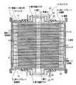
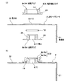
図1は、本実施形態に係る電気二重層キャパシタ(電気化学素子、以後、単にキャパシタと称す)の一例を示す縦断面図である。
図1に示すように、キャパシタ10は、ケーシング1と、このケーシング1の内部に積層収容される複数枚の電極シート2と、積層された積層体LAを上下方向から挟み込むように該積層体LAを定形保持する2つのL形リードプレート3とで構成され、前記2つのL形リードプレート3で前記積層体LAを定形保持することで、電極シート組立体ELが構成されるようにしている。
そして、複数枚の電極シート2の積層方向におけるケーシング1の両端には電解液を注入するための開口6,7がそれぞれ設けられている。
また、前記2つのL形リードプレート3の後記する保持壁32には絶縁膜13が設けられている。
Hereinafter, embodiments of the present invention will be described in detail with reference to the drawings.
FIG. 1 is a longitudinal sectional view showing an example of an electric double layer capacitor (electrochemical element, hereinafter simply referred to as a capacitor) according to the present embodiment.
As shown in FIG. 1, a
And the opening 6 and 7 for inject | pouring electrolyte solution are provided in the both ends of the casing 1 in the lamination direction of the
An
≪ケーシング≫
ケーシング1は、適宜の高さで上下を開口させた角形筒状の筒部1aと、この筒部1aの上下の開口部にそれぞれ取付けられる上下の蓋部1b,1bとで構成され、前記筒部1a内に複数枚の電極シート2を積層収容せしめた後に、前記筒部1aの上下の開口縁部に蓋部1b,1bの周辺縁部が曲げ加工やカシメ加工、あるいは溶着(融着)などによって取付けることで、前記電極シート組立体ELが電解液とともに密閉状に収容されるようにしている。
なお、前記筒部1aの高さは、絶縁性のセパレータ4を介して正極側と負極側とが交互に積層される電極シート2の積層枚数に相当する程度である。
そして、上下の蓋部1b,1bの中央部分には電解液を注入するための開口6,7が、後記の端子接続プラグ8,9によって備えられるようにしている。
≪Casing≫
The casing 1 is composed of a rectangular cylindrical tube portion 1a that is open at an appropriate height and upper and
The height of the cylindrical portion 1a is equivalent to the number of stacked
And the opening 6 and 7 for inject | pouring electrolyte solution is provided in the center part of the upper and
≪電極シート≫
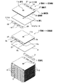
図2は、正極側と負極側の複数枚の電極シートを、セパレータと電極シートの一辺側のリード部間に介在されるシムとを介して交互に積層するその積層形態を示す斜視図である。図3は、積層形成された積層体を、2つのL形リードプレートによって上下から挟み込み保持する状態を示す斜視図である。
電極シート2は、正または負の電荷を貯めるため、アルミニウム箔などの導電性を有する材料から略四角形状でかつシート状に形成された集電箔2aの一辺側の両面を除いたその両面全体に電極層2b,2bを備えることで形成され、前記一辺側を不図示の正極側の外部端子と負極側の外部端子にそれぞれのL形リードプレート3を介して電気的に導通させることによって、前記各電極層2b,2bに貯められた電荷の取出し口としてのリード部2cとしている。
前記電極層2b,2bは、活性炭を主成分としており、前記集電箔2aの前記両面全体にわたって貼付けや塗布などにより略四角形状に形成されている。
≪Electrode sheet≫
FIG. 2 is a perspective view showing a lamination form in which a plurality of electrode sheets on the positive electrode side and the negative electrode side are alternately laminated via a separator and a shim interposed between lead portions on one side of the electrode sheet. . FIG. 3 is a perspective view showing a state in which the laminated body is sandwiched and held from above and below by two L-shaped lead plates.
Since the
The
そして、前記電極層2b,2bを備える電極シート2の中央部分には、図2および図3に示すように、複数枚の電極シート2を積層せしめたときにその積層方向に貫通する貫通孔11を確保形成するための適宜孔径を有する通孔11aが開口されている。
また、図2に示すように、電極層2b,2bを備える集電箔2aの他辺側の両側コーナーをR状にカットすることによって、介在されるセパレータ4へのダメージを低減することができる。これにより、ショートを防ぎ、生産歩留りを向上させることができる。
And in the center part of the
Moreover, as shown in FIG. 2, the damage to the intervening
リード部2cは、図2に示すように、電極シート2の一辺側に、適宜の幅をもってその辺方向に沿って形成され、L形リードプレート3に超音波溶接など適宜の溶着手段によって電気的に溶着接続されるように形成されている。
また、リード部2cには図示のように、長孔12が2ヶ所に設けられており、これによって、材料削減による軽量化を図ると同時に、同じく積層介在されるシム5側に設けられている長孔14との積層連通によって空間が形成される。この空間は、電解液の分解などでガスが生じた場合に、体積増加分を受け持つバッファ部として機能させることができる。
As shown in FIG. 2, the
Further, as shown in the figure, the
前記正極側の電極シート2と負極側の電極シート2との間に介在されるセパレータ4の材質としては特に限定されるものではないが、電解液の保液率が高く、しかも、例えばN2などの乾燥流体をキャリアガスとして適宜に透過する適宜の絶縁部材であることが好ましい。その一例としてセルロース系が挙げられる。
このセパレータ4は、前記電極シート2の電極層2bに相当する大きさの略四角形状のシート状に形成され、積層隣り合う異極の電極シート2を絶縁する。
また、セパレータ4の中央部分には前記電極シート2に設けられている前記通孔11aとによって前記貫通孔11を確保形成するための略同じ程度の孔径を有する通孔11bが設けられている。
The material of the
The
Further, a through
シム5は、導電性を有する略短冊状の部材であり、その角部が適宜R形状に面取りされるとともに、前記リード部2cの長孔12に対応した長孔14が適宜形成されている。
このシム5は、積層隣り合う前記電極シート2のリード部2cの間や、端に位置する前記電極シート2と前記L形リードプレート3との間に介在されるように配置されるようになっている。ここで、電極シート2と前記L形リードプレート3との間の距離は、同極の電極シート2のリード部2c間における距離に対して短いため、実際には、長さが異なる2種類のシム5がある。
The
The
≪L形リードプレート≫
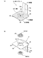
図4は、L形リードプレートを示す斜視図である。図5は、L形リードプレートに対する端子接続プラグの取付け構造を示す要部の拡大縦断面図である。
L形リードプレート3は、積層された電極シート2群を、連結軸20による連結により定形保持する保持壁32と、前記正極側の電極シート2のリード部2cが電気的に導通するように溶着より接続される集電壁31とを備えている。
≪L-shaped lead plate≫
FIG. 4 is a perspective view showing an L-shaped lead plate. FIG. 5 is an enlarged vertical cross-sectional view of the main part showing the structure for attaching the terminal connection plug to the L-shaped lead plate.
The L-shaped
保持壁32は、正極側と負極側の前記電極シート2を、そのリード部2cを相反する方向に向け、電極層2b同士を適合積層せしめた時の平面形状と略同じ形状を呈する四角形状に形成されている。
そして、図4(a)に示すように、集電壁31が折り曲げ連設される保持壁32の一辺側を除くその表面(内面)に絶縁膜13を貼り付けることによって、電極シート2の電極層2bが接する部分の絶縁処理を施している。ちなみに、この絶縁膜13は、テープ状やフィルム状を呈している。
このように、絶縁膜13を貼り付けて絶縁処理を施すことで、絶縁紙などの部品を削減することができ、その分、生産工数の削減とコストの削減が期待できる。
なお、図4(a)に示すように、絶縁膜13は前記保持壁32に取付けられる端子接続プラグ8,9の後記する雄側プラグ8b,9bを覆うように備えられている。
The holding
And as shown to Fig.4 (a), by sticking the insulating
As described above, by applying the insulating treatment by attaching the insulating
As shown in FIG. 4A, the insulating
また、図4(b)に示すように、保持壁32の中央部分には取付孔16,17がそれぞれ設けられており、図5に示すように、前記端子接続プラグ8,9がシール性の高いOリング18をそれぞれ介在せしめた状態で前記取付孔16,17の開口縁を挟み込むように該取付孔16,17に取付けられるようにしている(図5(b)参照)。
Further, as shown in FIG. 4B, mounting
集電壁31は、前記保持壁32,4bの一辺縁から同辺縁幅より狭い幅をもって一体に折り曲げ連設されると共に、その両辺縁部を縁方向に沿って内側(電極シート2側)に折り曲げることで、前記電極シート2のリード部2cを溶着により電気的に接続するための屈曲部19aとしている。
また、集電壁31の幅方向の略中央部分には前記屈曲部19aの曲げ方向で前記電極シート2の積層方向に延びるビード部9bが凸状に形成されている。
The
In addition, a
端子接続プラグ8,9は、不図示の正極側と負極側の外部端子がねじ込み方式にて取付けられるものであり、雌側プラグ8a,9aと雄側プラグ8b,9bとで構成されている。
雌側プラグ8a,9aは、一端外周に鍔部23を備えると共に、軸芯開口部に雌ねじ24を備えている。雄側プラグ8b,9bは、一端外周に鍔部25を備え、軸芯に前記開口6,7を設けると共に、外周面に前記雌ねじ24に螺合連結させる雄ねじ26を備えている。
また、図1に示すように、前記端子接続プラグ8の前記雌側プラグ8aに雄側端子40が、前記端子接続プラグ9の前記雄側プラグ9aに雌側端子41がそれぞれ螺合装着されており、図7に示すように、複数個のキャパシタ10…を直列に配置し、一方のキャパシタ10の開口7と、直列隣り合う他方のキャパシタ10の開口6とを直結させた状態で複数個のキャパシタ10…を接続することができるようにしている。
前記雄側端子40と前記雌側端子41とは互いに嵌り合う形状に形成されており、前記雄側端子40の外周面に雄ねじ42を備え、前記雌側端子41の内周面に前記雄ねじ42に螺合連結させる雄ねじ43を備えている。
なお、図示を省略しているが、前記端子接続プラグ8側に雌側端子を備え、前記端子接続プラグ9側に雄側端子を備えるもよく、特に限定されるものではない。
The terminal connection plugs 8 and 9 have positive and negative external terminals (not shown) attached thereto by screwing, and are composed of
The female side plugs 8a and 9a are provided with a
Further, as shown in FIG. 1, a
The
In addition, although illustration is abbreviate | omitted, a female terminal may be provided in the said
図2および図3において、連結孔27,28,29は、前記電極シート2のリード部2cと、前記シム5、そして前記L形リードプレート3の保持壁32にそれぞれ備えられており、複数枚の電極シート2を、図2に示すように、セパレータ4と電極シート2の一辺側のリード部2c間に介在されるシム5とを介して交互に積層せしめて積層体LAを形成する。
そして、図3に示す方向から積層体LAにL形リードプレート3をそれぞれセットせしめた後に、前記連結孔27,28,29に亘って4本の前記連結軸20…をそれぞれ挿通せしめて前記積層体LAの積層形態を定形保持することで、電極シート組立体ELの製造が完了する。
2 and 3, the connecting
Then, after the L-shaped
しかして、図2および図3に示すように、複数枚の正極側の電極シート2と負極側の電極シート2を、それぞれのリード部2cを相反する方向に向けた状態で、セパレータ4とシム5とをそれぞれ介在させながら交互に積層せしめる。
そして、積層された電極シート2群に正極側と負極側のそれぞれのL形リードプレート3をセットすると共に、四隅コーナーにおいてそれぞれ積層方向に連通する前記連結孔27,28,29にわたって4本の前記連結軸20…をそれぞれ挿通せしめることで、電極シート2群の積層形態が定形保持される。これによって形成された積層体LAの中央部分には積層方向に貫通すると共に、L形リードプレート3の保持壁32に端子接続プラグ8,9によって備えられた開口6,7に同軸上に連通する貫通孔11が確保形成される。
このようにして、L形リードプレート3によって積層形態が定形保持されることで形成される電極シート組立体ELのそれぞれのリード部2cを、前記L形リードプレート3の集電壁31にそれぞれ超音波溶着などにより電気的に接続せしめた後に、電極シート2群をケーシング1の筒部1a内に収容させる共に、該筒部1aの上下開口部に上下の蓋部1b,1bを曲げ加工やカシメ加工などによって取付ける。すると、前記L形リードプレート3の保持壁32にそれぞれ備えられた開口6,7を有するそれぞれの端子接続プラグ8,9が上下の蓋部1b,1bの中央部分においてシール部材30によってシールされた状態で外部突出することで、密閉されたケーシング1の両端に、開口6,7が互いに対向して設けられたキャパシタ10が製作構成されるものである。
As shown in FIGS. 2 and 3, the
Then, the L-shaped
In this way, the
≪電極シートの送風・減圧乾燥、電解液の注入≫
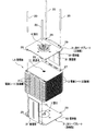
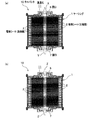
図6は、電極シート組立体をケーシングに収容させた後に行う電極シートなどを含めたケーシング内部の乾燥、そして電解液の注入を示す作業工程手順の縦断面図である。
まず始めに、図6(a)に示すように、一方の開口7側からケーシング1内に例えばN2などの乾燥流体をキャリアガスとして送り込む(矢印X)と共に、他方の開口6側から排気(矢印Y)を行う電極シート2の乾燥処理を実行する。このとき、開口6側を閉塞せしめた状態で、開口7側からケーシング1内へ乾燥流体を送り込み、ある程度の乾燥流体をケーシング1内に送り込んだ後に、開口6を開放させて排気するのもよい。
開口7側からケーシング1内に送り込まれたキャリアガスは、積層方向の貫通孔11を通りながら積層収容されている各電極シート2に接触せしめながら該各電極シート2をその内側から送風乾燥せしめる。
≪Blowing of electrode sheet, drying under reduced pressure, injection of electrolyte solution≫
FIG. 6 is a longitudinal sectional view of a work process procedure showing drying of the casing including the electrode sheet and the like injected after the electrode sheet assembly is accommodated in the casing, and injection of the electrolytic solution.
First, as shown in FIG. 6A, a dry fluid such as N 2 is sent as a carrier gas into the casing 1 from one
The carrier gas fed into the casing 1 from the
つぎに、一方の開口7側からケーシング1内を加圧する一方で、他方の開口6側からケーシング1内を減圧する電極シート2の乾燥処理を実行する。このとき、開口6側を閉塞せしめた状態で、開口7側からケーシング1内を加圧したり、または、開口7側を閉塞せしめた状態で、開口6側からケーシング1内を減圧するなど、ある程度の差圧域までケーシング1の内部と外部との間に差圧をつける。
このように、ケーシング1の内部と外部との間に差圧をつけることで、この差圧を利用して、電極シート2を含めてケーシング1の内部に気泡の残留などがない加圧・減圧乾燥を効果的かつ短時間で行うことができる。
Next, while the inside of the casing 1 is pressurized from the one
In this way, by applying a differential pressure between the inside and the outside of the casing 1, pressurization / decompression is performed by using this differential pressure so that no bubbles remain in the casing 1 including the
このように、送風乾燥処理と加圧・減圧乾燥処理によってケーシング1内の電極シート2を効果的かつ短時間で乾燥した後、図6(b)に示すように、両開口6,7からケーシング1内に電解液を注入(矢印Z)する注入処理を実行する。このとき、ケーシング1内部を減圧雰囲気に保持した状態で一方または双方の開口6,7からケーシング1の内部に電解液を注入することで、電解液は貫通孔11を通ってケーシング1内部に吸込まれるように隅々まで速やかに行き渡る。つまり、電解液は積層体LAの積層された各電極シート2全体にその内側から満遍なく速やかに行き渡り接触せしめる。これにより、積層された電極シート2全体に電解液を効率的に接触含浸させることができる。
Thus, after the
しかして、前記した本実施形態の電極シート2の送風乾燥、加圧・減圧乾燥、そして電解液の注入処理方法によれば、ケーシング1の両端に設けた開口6,7から同ケーシング1の内部に、一方の開口7を入口、他方の開口6を出口として例えばキャリアガスを送り込むことで、積層収容されている電極シート2などを効率的に送風乾燥、加圧・減圧乾燥させることができる。
また、一方の開口7からケーシング1の内部を加圧したり、他方の開口6からケーシング1の内部を減圧するなどのケーシング1の内部と外部との間に差圧をつけることで、この差圧を利用して、電極シート2などの加圧・減圧乾燥を効果的かつ短時間で行うことができる。
しかも、前記差圧、特にケーシング1の内部を減圧雰囲気に保持した状態で一方または双方の開口6,7からケーシング1の内部に電解液を注入することで、電解液はケーシング1の内部に吸込まれるように隅々まで速やかに行き渡る。つまり、電解液は積層された電極シート2全体に満遍なく速やかに行き渡り接触せしめる。これにより、積層された電極シート2に電解液を効率的に含浸させることができる。
また、開口6,7はケーシング1の両端に互いに対向する位置関係で設けられていることで、前記キャリアガスや電解液などの流体がケーシング1の内部をスムーズに流通することが期待できることから、前記乾燥処理と積層された電極シート2への電解液の接触含浸とを効果的かつ短時間で行うことができる。
Thus, according to the above-described method of blowing and drying the
Further, by applying a differential pressure between the inside of the casing 1 and the outside, such as pressurizing the inside of the casing 1 from one
Moreover, the electrolyte is sucked into the casing 1 by injecting the electrolyte into the casing 1 through one or both of the
Further, since the
さらに、ケーシング1の両端の両開口6,7と、収容された積層体LAの電極シート2の積層方向に貫通する貫通孔11とが、ケーシング1の両端略中央部分ならびに電極シート2の略中央部分において同軸対向するようにそれぞれ設けられていることで、前記両開口6,7から行われる前記キャリアガスの送風、排気、そしてケーシング1の内部の加圧・減圧、さらに電解液の注入において、ケーシング1の内周面に沿う電極シート2の周りから行われるキャリアガスの接触や電極液の接触のみならず、貫通孔11を通して電極シート2の中央部分においても前記キャリアガスの接触や電解液との接触が行われる。これによって、キャリアガスや加圧・減圧による電極シート2の乾燥速度を促進させることができ、そして電解液の電極シート2全体への含浸速度を促進させることができることから、キャパシタ10の生産性の向上が期待できる。
Furthermore, both the
また、前記各電極シート2の間に介在されるセパレータ4に、電極シート2の積層方向の貫通孔11に連通させた通孔11aを設けたことで、前記貫通孔11を通る前記キャリアガスや電解液の流れがよくなる。これによって、キャリアガスや加圧・減圧による電極シート2の乾燥速度をより一層効果的に促進させることができ、そして電解液の電極シート2全体への含浸速度をもより一層効果的に促進させることができる。
Further, the
≪電極シートの送風・減圧乾燥、電解液を注入する処理方法≫
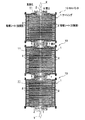
図7は、ケーシングの両端に設けた開口を介して複数個のキャパシタ同士を接続して行う積層された電極シートの乾燥と、電解液の注入などの処理方法を示す概略図である。
図7に示すように、複数個のキャパシタ10…を直列に配置し、一方のキャパシタ10の開口7と直列隣り合う他方のキャパシタ10の開口6とを、それぞれの端子接続プラグ8,9に備えられている雌側端子40と雄側端子41との螺合によって接続することにより、複数個のキャパシタ10…同士を直列状に連通させる。
≪Blowing of electrode sheet, drying under reduced pressure, processing method of injecting electrolyte≫
FIG. 7 is a schematic view showing a processing method such as drying of a laminated electrode sheet and injection of an electrolytic solution performed by connecting a plurality of capacitors through openings provided at both ends of the casing.
As shown in FIG. 7, arranged plurality of
このようにして、複数個のキャパシタ10…同士を直列状に連通させた後に、図示下段に位置するキャパシタ10の開口7から前記の実施形態のように、例えばキャリアガスを送り込む(矢印X)と共に、図示上段に位置するキャパシタ10の開口6から排気(矢印Y)を行うケーシング1内の電極シート2の乾燥処理を実行する。
このとき、前記の実施形態において詳述したように、図示上段のキャパシタ10の開口6側を閉塞せしめた状態で、図示下段のキャパシタ10の開口7側から乾燥流体を送り込み、ある程度の乾燥流体を連通する各キャパシタ10…のケーシング1内に送り込んだ後に、前記開口6を開放させて排気するもよい。
このように、複数個のキャパシタ10…を直列状に連通させ、図示下段のキャパシタ10の開口7から送り込まれたキャリアガスは、各キャパシタ10…のケーシング1内に流入せしめ、各ケーシング1…に積層収容されている電極シート2群の積層方向の貫通孔11を通りながら前記各電極シート2に接触せしめて、連通させた各キャパシタ10…のケーシング1内を併せて(同時に)送風乾燥する。つまり、各ケーシング1内に収容されている前記電極シート組立体ELの前記各電極シート2をその内側から同時に送風乾燥せしめる。
In this way, after the plurality of
At this time, as described in detail in the above embodiment, with the
In this way, the plurality of
つぎに、前記の実施形態において詳述したように、図示下段の前記キャパシタ10の開口7から各キャパシタ10…のケーシング1内を加圧する一方で、図示上段の前記キャパシタ10の開口6から各キャパシタ10…のケーシング1内を減圧する電極シート2の乾燥処理を実行する。このとき、前記開口6を閉塞せしめた状態で、前記開口7から連通させた各キャパシタ10…のケーシング1内を加圧したり、または、前記開口7を閉塞せしめた状態で、開口6から連通させた各キャパシタ10…のケーシング1内を減圧するなど、ある程度の差圧域まで前記各キャパシタ10…のケーシング1の内部と外部との間に差圧をつける。
このように、ケーシング1の内部と外部との間に差圧をつけることで、この差圧を利用して、連通させた各キャパシタ10…のケーシング1内に収容された積層体LAの電極シート2などの加圧・減圧乾燥を効果的かつ短時間で行うことができる。
Next, as described in detail in the above embodiment, the inside of the casing 1 of each
Thus, by applying a differential pressure between the inside and the outside of the casing 1, the electrode sheet of the laminate LA accommodated in the casing 1 of each of the
このように、送風処理と加圧・減圧処理によって連通させた各キャパシタ10…のケーシング1内の電極シート2を効果的かつ短時間で乾燥処理した後、前記の実施形態のように、図示上段のキャパシタ10の開口6、そして図示下段のキャパシタ10の開口7からそれぞれ電解液を注入(矢印Z)する注入処理を開始する。
このとき、各キャパシタ10…のケーシング1内部を減圧雰囲気に保持した状態で前記開口6,7の一方または双方から電解液を注入することで、電解液は各キャパシタ10…の貫通孔11を通って各キャパシタ10…のケーシング1内部に吸込まれるように隅々まで速やかに行き渡る。つまり、電解液は積層体LAの積層された電極シート2全体にその内側から満遍なく速やかに行き渡り接触せしめる。これにより、積層された電極シート2全体に電解液を効率的に接触含浸させることができる。
Thus, after the
At this time, by injecting the electrolytic solution from one or both of the
しかして、前記した本実施形態における電極シート2の送風乾燥、加圧・減圧乾燥、そして電解液の注入処理方法によれば、複数個のキャパシタ10…同士を、ケーシング1両端の開口6,7にて接続連通せしめた状態で前記したキャリアガスや減圧・加圧による乾燥と、電解液の注入とを複数個のキャパシタ10…に併せて(同時に)行うことができる。
すなわち、ケーシング1に収容された積層体LAの電極シート2の乾燥処理、そして前記電極シート2に電解液を接触含浸させるために該電解液を注入するなど一連の処理を複数個まとめて一緒(一同)に行うことができることで、その処理が大幅に改善され、その分、1個当たりのキャパシタ10の生産コストを抑えて、安価なキャパシタ10を提供することができる。
Thus, according to the blow drying, pressurizing / depressurizing drying, and electrolytic solution injecting method of the
That is, a plurality of series of processes such as drying treatment of the
1 ケーシング
1a 筒部
1b 蓋部
2 電極シート
2a 集電箔
2b 電極層
2c リード部
3 L形リードプレート
31 集電壁
32 保持壁
4 セパレータ
5 シム
6,7 開口
8,9 端子接続プラグ
10 キャパシタ
11 貫通孔
11a,11b 通孔
EL 電極シート組立体
LA 積層体
DESCRIPTION OF SYMBOLS 1 Casing
Claims (5)
前記電極シートの積層方向におけるケーシングの両端に、それぞれケーシングの内部に通じる開口を互いに対向させて設け、前記開口のうち少なくとも一方を、前記電解液を注入可能に構成したことを特徴とする電気化学素子。 An electrochemical element in which a laminate in which a plurality of electrode sheets are laminated and an electrolytic solution are housed in a casing,
Electrochemically characterized in that at both ends of the casing in the stacking direction of the electrode sheet, openings that respectively lead to the inside of the casing are provided to face each other, and at least one of the openings is configured to be able to inject the electrolytic solution. element.
電気化学素子のケーシングの両端に設けられている開口同士を接続することにより、複数個の電気化学素子同士を連通状態と成し、前記ケーシングに収容された積層体の各電極シートの乾燥ならびに電解液の注入を複数個の電気化学素子に対して併せて行うことができるようにしたことを特徴する電気化学素子の処理方法。
It is the processing method of the electrochemical element of any one of Claims 1-4, Comprising:
By connecting openings provided at both ends of the casing of the electrochemical element, a plurality of electrochemical elements are brought into communication with each other, and drying and electrolysis of each electrode sheet of the laminate accommodated in the casing are performed. A method for treating an electrochemical element, characterized in that the liquid can be injected into a plurality of electrochemical elements.
Priority Applications (1)
| Application Number | Priority Date | Filing Date | Title |
|---|---|---|---|
| JP2005144089A JP2006324322A (en) | 2005-05-17 | 2005-05-17 | Electrochemical element and processing method thereof |
Applications Claiming Priority (1)
| Application Number | Priority Date | Filing Date | Title |
|---|---|---|---|
| JP2005144089A JP2006324322A (en) | 2005-05-17 | 2005-05-17 | Electrochemical element and processing method thereof |
Publications (1)
| Publication Number | Publication Date |
|---|---|
| JP2006324322A true JP2006324322A (en) | 2006-11-30 |
Family
ID=37543799
Family Applications (1)
| Application Number | Title | Priority Date | Filing Date |
|---|---|---|---|
| JP2005144089A Withdrawn JP2006324322A (en) | 2005-05-17 | 2005-05-17 | Electrochemical element and processing method thereof |
Country Status (1)
| Country | Link |
|---|---|
| JP (1) | JP2006324322A (en) |
Cited By (2)
| Publication number | Priority date | Publication date | Assignee | Title |
|---|---|---|---|---|
| JP2013539606A (en) * | 2010-09-06 | 2013-10-24 | オーユー スケルトン テクノロジーズ | Supercapacitor with high specific capacity and energy density and structure of said supercapacitor |
| JP2013235664A (en) * | 2012-05-07 | 2013-11-21 | Toyota Industries Corp | Power storage device |
-
2005
- 2005-05-17 JP JP2005144089A patent/JP2006324322A/en not_active Withdrawn
Cited By (2)
| Publication number | Priority date | Publication date | Assignee | Title |
|---|---|---|---|---|
| JP2013539606A (en) * | 2010-09-06 | 2013-10-24 | オーユー スケルトン テクノロジーズ | Supercapacitor with high specific capacity and energy density and structure of said supercapacitor |
| JP2013235664A (en) * | 2012-05-07 | 2013-11-21 | Toyota Industries Corp | Power storage device |
Similar Documents
| Publication | Publication Date | Title |
|---|---|---|
| JP4140311B2 (en) | Method for manufacturing case for power storage element | |
| JP4670430B2 (en) | Electrochemical devices | |
| KR101230994B1 (en) | Large-sized Battery | |
| CN110521020B (en) | Method of making an electric vehicle battery cell with a polymer frame support | |
| US10879573B2 (en) | Energy storage apparatus and method of manufacturing energy storage apparatus | |
| JP2003045760A (en) | Multilayer electric double layer capacitor module | |
| CN104641486B (en) | Battery unit with the fixed cover board in locking manner of the shape in shell | |
| CN101273426B (en) | Multilayer electrochemical energy storage device and method of manufacturing the same | |
| US20060210874A1 (en) | Electrode for an electrochemical cell, electrode coil, electrochemical cell, and production method | |
| CN114041213B (en) | Power storage device | |
| WO2018003308A1 (en) | Electrochemical gas sensor | |
| WO2013125153A1 (en) | Electricity storage element fabrication method | |
| JP2007201383A (en) | Power accumulation device | |
| JP2006324322A (en) | Electrochemical element and processing method thereof | |
| JPWO2005052967A1 (en) | Capacitor | |
| US9030805B2 (en) | Capacitor and capacitor module using the same | |
| US4683639A (en) | Method of manufacturing an electrolytic double-layer capacitor | |
| JP4518625B2 (en) | Electric double layer capacitor | |
| KR20040038045A (en) | Electric energy storage device and method for manufacturing the same | |
| KR101306600B1 (en) | Method for manufacturing super capacitor of surface mount type | |
| JP2020145113A (en) | Manufacturing method of power storage module and manufacturing device for power storage module | |
| CN110268492A (en) | Electrode jig and electrode for aluminum electrolytic capacitor manufacturing method | |
| JP4138443B2 (en) | Electrochemical capacitor and method for producing electrochemical capacitor | |
| KR20170113906A (en) | Electrochemical energy storage device of axial type | |
| JP2006135119A (en) | Square electrode cell, manufacturing method thereof, and electric double layer capacitor using the same |
Legal Events
| Date | Code | Title | Description |
|---|---|---|---|
| A300 | Withdrawal of application because of no request for examination |
Free format text: JAPANESE INTERMEDIATE CODE: A300 Effective date: 20080805 |