JP2006310285A - Secondary battery and its formation method - Google Patents
Secondary battery and its formation method Download PDFInfo
- Publication number
- JP2006310285A JP2006310285A JP2006092137A JP2006092137A JP2006310285A JP 2006310285 A JP2006310285 A JP 2006310285A JP 2006092137 A JP2006092137 A JP 2006092137A JP 2006092137 A JP2006092137 A JP 2006092137A JP 2006310285 A JP2006310285 A JP 2006310285A
- Authority
- JP
- Japan
- Prior art keywords
- electrode
- secondary battery
- electrode assembly
- welded
- assembly
- Prior art date
- Legal status (The legal status is an assumption and is not a legal conclusion. Google has not performed a legal analysis and makes no representation as to the accuracy of the status listed.)
- Granted
Links
- 238000000034 method Methods 0.000 title claims abstract description 34
- 230000015572 biosynthetic process Effects 0.000 title abstract description 5
- 238000003466 welding Methods 0.000 claims abstract description 51
- 238000005452 bending Methods 0.000 claims description 2
- 229910052751 metal Inorganic materials 0.000 description 6
- 239000002184 metal Substances 0.000 description 6
- 239000002002 slurry Substances 0.000 description 5
- WHXSMMKQMYFTQS-UHFFFAOYSA-N Lithium Chemical compound [Li] WHXSMMKQMYFTQS-UHFFFAOYSA-N 0.000 description 4
- 229910052744 lithium Inorganic materials 0.000 description 4
- 239000000463 material Substances 0.000 description 4
- 239000011149 active material Substances 0.000 description 3
- 238000007599 discharging Methods 0.000 description 3
- 239000007787 solid Substances 0.000 description 3
- XEEYBQQBJWHFJM-UHFFFAOYSA-N Iron Chemical compound [Fe] XEEYBQQBJWHFJM-UHFFFAOYSA-N 0.000 description 2
- 229910052782 aluminium Inorganic materials 0.000 description 2
- XAGFODPZIPBFFR-UHFFFAOYSA-N aluminium Chemical compound [Al] XAGFODPZIPBFFR-UHFFFAOYSA-N 0.000 description 2
- 239000003792 electrolyte Substances 0.000 description 2
- 239000011888 foil Substances 0.000 description 2
- 239000011244 liquid electrolyte Substances 0.000 description 2
- 229910001416 lithium ion Inorganic materials 0.000 description 2
- 239000002904 solvent Substances 0.000 description 2
- 229910000838 Al alloy Inorganic materials 0.000 description 1
- RYGMFSIKBFXOCR-UHFFFAOYSA-N Copper Chemical compound [Cu] RYGMFSIKBFXOCR-UHFFFAOYSA-N 0.000 description 1
- HBBGRARXTFLTSG-UHFFFAOYSA-N Lithium ion Chemical compound [Li+] HBBGRARXTFLTSG-UHFFFAOYSA-N 0.000 description 1
- 229910018095 Ni-MH Inorganic materials 0.000 description 1
- 229910018477 Ni—MH Inorganic materials 0.000 description 1
- 239000011324 bead Substances 0.000 description 1
- 239000011230 binding agent Substances 0.000 description 1
- 239000004020 conductor Substances 0.000 description 1
- 229910052802 copper Inorganic materials 0.000 description 1
- 239000010949 copper Substances 0.000 description 1
- 230000008878 coupling Effects 0.000 description 1
- 238000010168 coupling process Methods 0.000 description 1
- 238000005859 coupling reaction Methods 0.000 description 1
- 239000007772 electrode material Substances 0.000 description 1
- 239000008151 electrolyte solution Substances 0.000 description 1
- 239000011245 gel electrolyte Substances 0.000 description 1
- 229910052739 hydrogen Inorganic materials 0.000 description 1
- 239000001257 hydrogen Substances 0.000 description 1
- 229910052742 iron Inorganic materials 0.000 description 1
- 235000015110 jellies Nutrition 0.000 description 1
- 239000008274 jelly Substances 0.000 description 1
- 238000013021 overheating Methods 0.000 description 1
- 239000004014 plasticizer Substances 0.000 description 1
- 239000005518 polymer electrolyte Substances 0.000 description 1
- 238000003756 stirring Methods 0.000 description 1
- 238000004804 winding Methods 0.000 description 1
Images


Classifications
-
- H—ELECTRICITY
- H01—ELECTRIC ELEMENTS
- H01M—PROCESSES OR MEANS, e.g. BATTERIES, FOR THE DIRECT CONVERSION OF CHEMICAL ENERGY INTO ELECTRICAL ENERGY
- H01M50/00—Constructional details or processes of manufacture of the non-active parts of electrochemical cells other than fuel cells, e.g. hybrid cells
- H01M50/50—Current conducting connections for cells or batteries
- H01M50/528—Fixed electrical connections, i.e. not intended for disconnection
-
- H—ELECTRICITY
- H01—ELECTRIC ELEMENTS
- H01M—PROCESSES OR MEANS, e.g. BATTERIES, FOR THE DIRECT CONVERSION OF CHEMICAL ENERGY INTO ELECTRICAL ENERGY
- H01M10/00—Secondary cells; Manufacture thereof
- H01M10/04—Construction or manufacture in general
- H01M10/0431—Cells with wound or folded electrodes
-
- H—ELECTRICITY
- H01—ELECTRIC ELEMENTS
- H01M—PROCESSES OR MEANS, e.g. BATTERIES, FOR THE DIRECT CONVERSION OF CHEMICAL ENERGY INTO ELECTRICAL ENERGY
- H01M10/00—Secondary cells; Manufacture thereof
- H01M10/05—Accumulators with non-aqueous electrolyte
- H01M10/058—Construction or manufacture
- H01M10/0587—Construction or manufacture of accumulators having only wound construction elements, i.e. wound positive electrodes, wound negative electrodes and wound separators
-
- H—ELECTRICITY
- H01—ELECTRIC ELEMENTS
- H01M—PROCESSES OR MEANS, e.g. BATTERIES, FOR THE DIRECT CONVERSION OF CHEMICAL ENERGY INTO ELECTRICAL ENERGY
- H01M4/00—Electrodes
- H01M4/02—Electrodes composed of, or comprising, active material
- H01M4/64—Carriers or collectors
- H01M4/70—Carriers or collectors characterised by shape or form
-
- H—ELECTRICITY
- H01—ELECTRIC ELEMENTS
- H01M—PROCESSES OR MEANS, e.g. BATTERIES, FOR THE DIRECT CONVERSION OF CHEMICAL ENERGY INTO ELECTRICAL ENERGY
- H01M50/00—Constructional details or processes of manufacture of the non-active parts of electrochemical cells other than fuel cells, e.g. hybrid cells
- H01M50/10—Primary casings; Jackets or wrappings
- H01M50/147—Lids or covers
- H01M50/166—Lids or covers characterised by the methods of assembling casings with lids
- H01M50/171—Lids or covers characterised by the methods of assembling casings with lids using adhesives or sealing agents
-
- H—ELECTRICITY
- H01—ELECTRIC ELEMENTS
- H01M—PROCESSES OR MEANS, e.g. BATTERIES, FOR THE DIRECT CONVERSION OF CHEMICAL ENERGY INTO ELECTRICAL ENERGY
- H01M50/00—Constructional details or processes of manufacture of the non-active parts of electrochemical cells other than fuel cells, e.g. hybrid cells
- H01M50/40—Separators; Membranes; Diaphragms; Spacing elements inside cells
- H01M50/463—Separators, membranes or diaphragms characterised by their shape
- H01M50/469—Separators, membranes or diaphragms characterised by their shape tubular or cylindrical
-
- Y—GENERAL TAGGING OF NEW TECHNOLOGICAL DEVELOPMENTS; GENERAL TAGGING OF CROSS-SECTIONAL TECHNOLOGIES SPANNING OVER SEVERAL SECTIONS OF THE IPC; TECHNICAL SUBJECTS COVERED BY FORMER USPC CROSS-REFERENCE ART COLLECTIONS [XRACs] AND DIGESTS
- Y02—TECHNOLOGIES OR APPLICATIONS FOR MITIGATION OR ADAPTATION AGAINST CLIMATE CHANGE
- Y02E—REDUCTION OF GREENHOUSE GAS [GHG] EMISSIONS, RELATED TO ENERGY GENERATION, TRANSMISSION OR DISTRIBUTION
- Y02E60/00—Enabling technologies; Technologies with a potential or indirect contribution to GHG emissions mitigation
- Y02E60/10—Energy storage using batteries
-
- Y—GENERAL TAGGING OF NEW TECHNOLOGICAL DEVELOPMENTS; GENERAL TAGGING OF CROSS-SECTIONAL TECHNOLOGIES SPANNING OVER SEVERAL SECTIONS OF THE IPC; TECHNICAL SUBJECTS COVERED BY FORMER USPC CROSS-REFERENCE ART COLLECTIONS [XRACs] AND DIGESTS
- Y02—TECHNOLOGIES OR APPLICATIONS FOR MITIGATION OR ADAPTATION AGAINST CLIMATE CHANGE
- Y02P—CLIMATE CHANGE MITIGATION TECHNOLOGIES IN THE PRODUCTION OR PROCESSING OF GOODS
- Y02P70/00—Climate change mitigation technologies in the production process for final industrial or consumer products
- Y02P70/50—Manufacturing or production processes characterised by the final manufactured product
-
- Y—GENERAL TAGGING OF NEW TECHNOLOGICAL DEVELOPMENTS; GENERAL TAGGING OF CROSS-SECTIONAL TECHNOLOGIES SPANNING OVER SEVERAL SECTIONS OF THE IPC; TECHNICAL SUBJECTS COVERED BY FORMER USPC CROSS-REFERENCE ART COLLECTIONS [XRACs] AND DIGESTS
- Y10—TECHNICAL SUBJECTS COVERED BY FORMER USPC
- Y10T—TECHNICAL SUBJECTS COVERED BY FORMER US CLASSIFICATION
- Y10T29/00—Metal working
- Y10T29/49—Method of mechanical manufacture
- Y10T29/49002—Electrical device making
- Y10T29/49108—Electric battery cell making
- Y10T29/49114—Electric battery cell making including adhesively bonding
Landscapes
- Chemical & Material Sciences (AREA)
- Chemical Kinetics & Catalysis (AREA)
- Electrochemistry (AREA)
- General Chemical & Material Sciences (AREA)
- Engineering & Computer Science (AREA)
- Manufacturing & Machinery (AREA)
- Connection Of Batteries Or Terminals (AREA)
- Sealing Battery Cases Or Jackets (AREA)
- Secondary Cells (AREA)
Abstract
Description
本発明は、二次電池に関し、より詳細には、二次電池でのタブと缶との結合構造及びその形成方法に関する。 The present invention relates to a secondary battery, and more particularly to a tab-can coupling structure in a secondary battery and a method of forming the same.
二次電池は、再充電が可能であり、小型及び大容量化が可能であるという利点から、近年にその開発が急速になされ、使用も急速に増加しつつある。二次電池は、電極活物質によって、ニッケル−水素(Ni−MH)電池とリチウムイオン(Li−ion)電池などに分けられる。 Secondary batteries have been developed rapidly in recent years and their use is rapidly increasing due to the advantages that they can be recharged, and can be reduced in size and capacity. Secondary batteries are classified into nickel-hydrogen (Ni-MH) batteries and lithium ion (Li-ion) batteries according to the electrode active material.
リチウム二次電池の場合、電解質の種類によって、液体電解質を使用する場合と、固体ポリマー電解質、あるいは、ゲル状の電解質を使用する場合とに分けられる。リチウム二次電池は、更に、電極組立体が収容される容器の形態によって、缶状とパウチ状とに分けられる。 In the case of a lithium secondary battery, depending on the type of electrolyte, there are a case where a liquid electrolyte is used and a case where a solid polymer electrolyte or a gel electrolyte is used. The lithium secondary battery is further divided into a can shape and a pouch shape depending on the shape of the container in which the electrode assembly is accommodated.
缶状のリチウム二次電池では、電極組立体が、アルミニウム含有金属などの金属で深絞りなどの方法を通じて形成した缶に組み込まれる。通常、缶状の二次電池の構造では、液体電解質を使用することになる。 In a can-type lithium secondary battery, an electrode assembly is incorporated into a can formed by a method such as deep drawing using a metal such as an aluminum-containing metal. Usually, a liquid electrolyte is used in the structure of a can-shaped secondary battery.
一方、缶状の二次電池は、形態によって、角形と円筒形との電池に分けられる。角形は、容器を直方体状に、あるいは、直方体の側壁角に曲率を与えて薄く成形したものである。円筒形は、比較的大容量の電子電気機器に多く使用され、複数個が結合されて電池パックを形成する形態で多く使用される。 On the other hand, can-shaped secondary batteries are classified into rectangular and cylindrical batteries depending on the form. The square is formed by thinly forming a container in a rectangular parallelepiped shape or by giving a curvature to a side wall angle of the rectangular parallelepiped. The cylindrical shape is often used in relatively large-capacity electronic and electrical equipment, and is often used in a form in which a plurality are combined to form a battery pack.
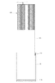
図1及び図2は、従来の円筒形リチウム二次電池の一例に対する構造を示す正断面図及び分解斜視図である。 1 and 2 are a front sectional view and an exploded perspective view showing a structure for an example of a conventional cylindrical lithium secondary battery.
図1及び図2を参照して、円筒形二次電池の形成方法を見てみると、まず、矩形の板状に形成された2つの電極25と、これらの電極の間に介在されて2つの電極の間の短絡を防止するセパレータ21、23とが積層され、渦状に巻き取られてゼリー・ロールと通称される電極組立体20を成す。各電極板は、金属箔からなる集電体に活物質のスラリーが塗布されてなる。
Referring to FIG. 1 and FIG. 2, a method for forming a cylindrical secondary battery will be described. First, two
電極板が巻かれる方向で、集電体の始端と終端とには、スラリーが塗布されない無地部が存在する。無地部には、一電極板に、通常、一つずつ電極タブ27、29が設けられる。電極タブ27、29は、円筒形の缶10と、缶10から絶縁されたキャップアセンブリ80に電気的に接続されて、充放電時に、電極組立体と外部回路とを連結するための通路の一部を形成する。電極組立体20において電極タブは、一つが円筒形の缶10の開口部方向である上方に、もう一つが、下方に電極から取り出されるように形成される。
In the direction in which the electrode plate is wound, there is a solid portion where the slurry is not applied at the start and end of the current collector. In the plain portion,
電極組立体は、上下に位置する上、下絶縁板13a、13bと順に缶の開口部を介して円筒形の缶10に投入される。電極組立体の缶内での移動を防ぐためのビードが缶に形成され、電解液が注入される。缶の開口部の内面に絶縁ガスケット30が設けられ、ガスケット30の内側に缶10の開口部を覆うキャップアセンブリ80が設けられる。
The electrode assembly is placed into the
キャップアセンブリ80として、ベントアセンブリ、PTC(正温度係数:Positive Thermal Coefficient)エレメント60、及び電極端子を持ったキャップアップ70が挿入される。ベントアセンブリは、通常、下側のベント40と、ベントの作用により破断され、電流の経路を切る電流遮断器(CID:Current Interrupt Device)50を備えてなる。
As the
そして、ガスケット30の内側に挿入されたキャップアップ70を栓として使用し、円筒形の缶10の開口部の壁体に内側方向及び下方向の圧力を加えて缶をシールするクランプ作業が行われる。また、電池の外部に外装材を施すチュービング(Tubing)作業が行われる。
Then, using the cap-
このような過程において、電極タブの連結を見てみると、電極組立体の電極タブのうち、下方に伸びたものは、下絶縁板を介在させた状態で缶の底面に溶接され、また、上方に伸びたものは、上絶縁板のホールを介して、キャップアセンブリのベントに概ね溶接される。 In such a process, when looking at the connection of the electrode tab, the electrode tab of the electrode assembly that extends downward is welded to the bottom surface of the can with the lower insulating plate interposed therebetween, The upward extension is generally welded to the vent of the cap assembly through a hole in the upper insulating plate.
上方に取り出される上向き電極タブ27とベント40の凹部42とを溶接するためには、溶接作業が便利なように、電極タブ27は、余分の長さを持つように形成される。そして、電極タブが折り曲げられながら、ベントアセンブリは、ガスケット30が嵌め込まれた缶の上側開口部に挿入される。このような工程は、ベントアセンブリと電極組立体20との間に、工程の便宜のための僅かの空間を必要とする。
In order to weld the
上向き電極タブが長くなり過ぎると、溶接後、タブの処理が困難であるので、作業性のある範囲内において上向き電極タブの長さを決める。溶接後、上向き電極タブの残りの部分が、キャップ組立体と電極組立体との間の空間に蛇行するように位置されることができ、上絶縁板は、上向き電極タブと電極組立体の他極性との短絡を防止する役割を果たせる。 If the upward electrode tab becomes too long, it is difficult to process the tab after welding. Therefore, the length of the upward electrode tab is determined within a workable range. After welding, the remaining portion of the upward electrode tab can be positioned to meander in the space between the cap assembly and the electrode assembly, and the upper insulating plate can be positioned on the other side of the upward electrode tab and the electrode assembly. Can play a role in preventing short circuit with polarity.
電極組立体20の巻取のための中空には、図2のようなセンターピン18を設けることができる。
A
下向き電極タブ29の溶接の場合、図3に部分的に示された断面図から分かるように、電極組立体20が缶10に引き込まれた後、電極組立体20の中心の空スペースを通じて溶接棒115を入れ、電極タブ29を缶10の底面に密着させた状態で、溶接棒に電流を流入して抵抗溶接を実施する。電極タブと缶との間には、溶接棒115の先細部が当接する部位に溶接点291が形成される。ところが、電極組立体の中心の小さい空間に溶接棒を入れて溶接を行う関係から、溶接棒を動かしながら溶接をしにくく、溶接点291が一つである1ポイント溶接をすることになる。
In the case of welding the
ところが、電極組立体の電極タブが、安全ベントや缶と溶接される際に、溶接が相当な強度で行われなければならない。溶接が十分に行われなかった場合には、電極タブと安全ベントあるいは缶との間の電気的接続は、表面接触によって行われやすい。表面接触による電気的接続は、接触抵抗を発生させ、この接触抵抗は、溶接されたものに比べて大きな抵抗値を持つ。したがって、電池の内部抵抗が増加し、充放電効率が低下してしまうという問題がある。 However, when the electrode tab of the electrode assembly is welded to a safety vent or can, the welding must be done with considerable strength. If the welding is not done sufficiently, the electrical connection between the electrode tab and the safety vent or can tends to be made by surface contact. The electrical connection by surface contact generates a contact resistance, which has a large resistance value compared to the welded one. Therefore, there exists a problem that the internal resistance of a battery will increase and charging / discharging efficiency will fall.
特に、缶の底面での1ポイント溶接の場合、引張力に抵抗する強度は、一定の基準を満足しやすいが、内部で電極組立体が回転するようになる場合、溶接点が中心側にあり一つだけあるため、回転に対抗する力は非常に弱い。したがって、電池の使用中でも溶接が外れて、内部抵抗が急激に増加してしまうという現象が生じ得る。そして、このような現象は、電極組立体が缶の内部で回転しやすい円筒形電池の場合に主として問題となる。 In particular, in the case of one-point welding at the bottom of the can, the strength to resist the tensile force is likely to satisfy a certain standard, but when the electrode assembly rotates inside, the welding point is on the center side. Because there is only one, the force against rotation is very weak. Therefore, even during use of the battery, a phenomenon may occur in which welding is disengaged and the internal resistance increases rapidly. Such a phenomenon becomes a problem mainly in the case of a cylindrical battery in which the electrode assembly is easy to rotate inside the can.
本発明は、前述した従来の二次電池の問題点を解決するためのもので、缶の底面と下向き電極タブとの間の電気的接続の信頼性を高めることのできる二次電池及びその形成方法を提供することを目的とする。 The present invention is to solve the above-described problems of the conventional secondary battery, and a secondary battery capable of improving the reliability of the electrical connection between the bottom surface of the can and the downward electrode tab and the formation thereof. It aims to provide a method.
本発明は、缶の底面と下向き電極タブとの間の溶接の強度を高め、接続部の内部抵抗を低く保持して、充放電効率と放電量を高めることのできる二次電池及びその形成方法を提供することを目的とする。 The present invention provides a secondary battery capable of increasing the strength of welding between the bottom surface of the can and the downward electrode tab, maintaining the internal resistance of the connection portion low, and increasing the charge / discharge efficiency and the discharge amount, and a method for forming the same. The purpose is to provide.
前記目的を達成するための本発明の二次電池は、電極タブが形成された2つの電極、及び前記2つの電極の間に介在されて前記2つの電極の間の短絡を防止するセパレータを有する電極組立体と、電極組立体を収容する容器状缶と、前記缶の開口部でガスケットを介在して前記缶を覆うキャップアセンブリと、を備える二次電池において、前記電極タブのうちの一つは、缶内で少なくとも1回折り曲げられ、缶の内面と少なくとも1つのポイントで溶接されることを特徴とする。 In order to achieve the above object, a secondary battery according to the present invention includes two electrodes having electrode tabs formed thereon, and a separator interposed between the two electrodes to prevent a short circuit between the two electrodes. One of the electrode tabs in a secondary battery comprising: an electrode assembly; a container-like can that houses the electrode assembly; and a cap assembly that covers the can through a gasket at an opening of the can. Is bent at least once in the can and welded to the inner surface of the can at at least one point.
本発明において、缶と溶接される電極タブは、互いに離隔された2以上のポイントで溶接されることが望ましく、缶の底面で溶接されるか、または、缶の内面で溶接されてもよい。 In the present invention, the electrode tab to be welded with the can is desirably welded at two or more points spaced apart from each other, and may be welded at the bottom surface of the can or at the inner surface of the can.
本発明において、缶の底面と溶接される電極タブは、二次電池内において2回以上折り曲げられてもよい。もし、本発明において、電極タブのうち、缶の底面と溶接される一つは、電極組立体の下端から取り出されて上部に折り曲げられ、前記缶の上部から下部に折り曲げられた後、前記電極組立体の下端で再び折り曲げられて、前記缶の底面と少なくとも2つのポイントで溶接されてもよい。この時、電極タブが折り曲げられる缶の上部は、缶の内面の長さを基準にして中間以上の部分を意味し、折り曲げが行われる部分は、缶の上端であってもよい。 In the present invention, the electrode tab welded to the bottom surface of the can may be bent twice or more in the secondary battery. In the present invention, one of the electrode tabs to be welded to the bottom surface of the can is taken out from the lower end of the electrode assembly, bent to the upper part, bent from the upper part to the lower part of the can, and then the electrode. It may be folded again at the lower end of the assembly and welded to the bottom of the can at at least two points. At this time, the upper portion of the can where the electrode tab is bent means a portion that is intermediate or higher with respect to the length of the inner surface of the can, and the upper portion of the can may be the portion that is bent.
本発明において、缶の底面と溶接される電極タブにおいて、底面と接する部分、あるいは、底面と平行な部分以外の部分の長さが、缶の側面と電極組立体の側面との間にあるタブ部分の長さと等しいとすると、この部分の電極タブの長さは、缶の長さよりも長く、缶の長さの2倍よりも短いことが望ましい。この時、電極タブが、底面と平行に形成される部分なしに缶の側面と溶接される場合、電極組立体の下方に取り出される電極タブの長さが缶の長さよりも長く、缶の長さの2倍よりも短くてもよい。 In the present invention, in the electrode tab welded to the bottom surface of the can, the length of the portion other than the portion in contact with the bottom surface or the portion parallel to the bottom surface is between the side surface of the can and the side surface of the electrode assembly. If it is equal to the length of the part, the length of the electrode tab in this part is preferably longer than the length of the can and shorter than twice the length of the can. At this time, when the electrode tab is welded to the side surface of the can without a portion formed parallel to the bottom surface, the length of the electrode tab taken out below the electrode assembly is longer than the length of the can, It may be shorter than twice.
前記目的を達成するための本発明の方法は、電池の形成方法において、缶に電極組立体の一つのタブを引き込ませ、電極組立体本体は引き込ませない状態で、電極タブを缶に2ポイント以上溶接させる段階と、電極タブを曲げて電極組立体を缶に引き込ませる段階と、を備えてなることを特徴とする。 According to the method of the present invention for achieving the above object, in the method of forming a battery, two tabs of the electrode tab are formed on the can in a state where the tab of the electrode assembly is retracted into the can and the electrode assembly body is not retracted. The step of welding as described above and the step of bending the electrode tab and retracting the electrode assembly into the can are provided.
本発明の方法において、通常、電極タブの溶接後には、下絶縁板を缶の底部に設けて、電極組立体を引き込ませるようになる。 In the method of the present invention, usually, after welding the electrode tab, a lower insulating plate is provided at the bottom of the can to retract the electrode assembly.
本発明によれば、二次電池において缶の底面と下向き電極タブとの間の溶接の強度を高めることができ、電気接続部の抵抗を低く保持して、全体の内部抵抗を下げ、充放電効率と放電量とを高めることができる。 According to the present invention, in the secondary battery, the strength of welding between the bottom surface of the can and the downward electrode tab can be increased, the resistance of the electrical connection portion is kept low, the overall internal resistance is lowered, and charging / discharging Efficiency and discharge amount can be increased.
特に、外部衝撃などにより電極組立体が回転して、缶の底面と下向き電極タブとの間の溶接が外れることで、電池の使用中に内部抵抗が急激に上昇してしまうという問題を防止して、二次電池の信頼性を高めることができる。 In particular, the electrode assembly rotates due to external impact, etc., and the weld between the bottom surface of the can and the downward electrode tab is disengaged, preventing the problem that the internal resistance suddenly increases during battery use. Thus, the reliability of the secondary battery can be improved.
以下、図面を参照しながら、実施形態に基づいて本発明をより詳細に見てみるとする。 Hereinafter, the present invention will be described in more detail based on embodiments with reference to the drawings.
図4は本発明の一実施形態によって、電極組立体の電極タブが缶に溶接され、電極タブが折り曲げられ、電極組立体が缶に挿入される過程を示す工程断面図、図5は本発明の一実施形態によって、電極組立体の電極タブが缶に溶接され、電極タブが折り曲げられ、電極組立体が缶に挿入される過程を示す工程断面図、図6は本発明の一実施形態によって、電極組立体の電極タブが缶に溶接され、電極タブが折り曲げられ、電極組立体が缶に挿入される過程を示す工程断面図である。 FIG. 4 is a process cross-sectional view illustrating a process in which the electrode tab of the electrode assembly is welded to the can, the electrode tab is bent, and the electrode assembly is inserted into the can according to an embodiment of the present invention. FIG. 6 is a process cross-sectional view illustrating a process in which the electrode tab of the electrode assembly is welded to the can, the electrode tab is bent, and the electrode assembly is inserted into the can according to an embodiment of the present invention. FIG. 6 is a process cross-sectional view illustrating a process in which the electrode tab of the electrode assembly is welded to the can, the electrode tab is bent, and the electrode assembly is inserted into the can.
まず、本発明の二次電池の形成過程を見てみると、従来のように矩形の板状に形成された2つの電極が積層され、渦状に巻き取られてゼリー・ロール状電極組立体を形成する。この時、これらの電極の間、及び2つの電極の下側あるいは上側には、セパレータが一つずつ位置するので、重なって巻き取られる2つの電極が当接する部分には、いずれにおいてセパレータが介在されて短絡が防止される。 First, looking at the formation process of the secondary battery according to the present invention, two electrodes formed in a rectangular plate shape as in the past are stacked and wound in a spiral shape to form a jelly-roll electrode assembly. Form. At this time, since a separator is positioned between these electrodes and below or above the two electrodes, the separator is interposed at any portion where the two electrodes wound up overlapped with each other. To prevent short circuit.
各電極板は、アルミニウムや銅からなる金属箔、あるいは、金属メッシュからなる集電体に、活物質スラリーが塗布されてなる。スラリーは、通常、粒状の活物質と補助導体及びバインダー並びに可塑剤などが、溶媒が添加された状態で撹拌されてなる。溶媒は、後の電極形成工程で除去される。 Each electrode plate is obtained by applying an active material slurry to a metal foil made of aluminum or copper, or a current collector made of a metal mesh. The slurry is usually prepared by stirring a granular active material, an auxiliary conductor, a binder, a plasticizer, and the like with a solvent added. The solvent is removed in a later electrode formation step.
電極板が巻かれる方向の、集電体の始端と終端とには、スラリーが塗布されない無地部が存在する。無地部には、一電極板に一つずつ電極タブが設けられ、電極タブは、一つが円筒形の缶の開口部方向である上方に、もう一つが下方に電極から取り出されるように形成される。 There is a solid portion to which the slurry is not applied at the start and end of the current collector in the direction in which the electrode plate is wound. In the plain part, one electrode tab is provided for each electrode plate, and the electrode tabs are formed so that one is taken out from the electrode in the upper direction, which is the direction of the opening of the cylindrical can. The
缶は、円筒形に、鉄材、アルミニウム合金などを用いて深絞り方法などで形成される。次いで、図4乃至図6のように、電極タブ129の溶接を含んで、電極組立体120と缶10とを結合させる段階が行われる。
The can is formed in a cylindrical shape by a deep drawing method using an iron material, an aluminum alloy, or the like. Next, as shown in FIGS. 4 to 6, the step of joining the
図を参照して、この過程を更に見てみると、図4のように、まず、電極タブ127、129が上下方に取り出される電極組立体120と、これを収容する円筒形の缶10とが用意される。電極組立体において、下方に取り出される電極タブ129は、電極組立体120の最外郭部で電極と連結され、電極と連結される端部以外の他端部は、電極組立体が引き込まれていない状態で、缶の内面の上端部の一部分に平行な状態に溶接点149で2ポイント以上強固に溶接される。
Referring to the drawing, this process will be further examined. As shown in FIG. 4, first, an
この時、図4のように、まず、下絶縁板113bが缶10の底面に設けられることも可能である。図5のように、電極タブ129を折り曲げた状態で、電極組立体120を缶10の内部に挿入する。つまり、図6のように、電極タブ129は、一部の区間で重なった状態で、電極組立体120と缶10の内面との間の空間に置かれるようになる。電極組立体と缶との間に空間がある製品の場合、重なった状態の電極タブが、電極組立体を缶の内部で移動しないように支持する役割を果たすこともできる。
At this time, as shown in FIG. 4, first, the lower insulating
図示していないが、他の実施形態によれば、下向き電極タブは、一部分で折り曲げられ、缶の内面に平行な部分と缶の底面に平行な末端部分とに分けられる。缶の内面に平行な部分は、缶の内面の長さの約1.5倍程度の長さを有し、缶の底面に平行な末端部分は、円筒形の缶の底面の径とほぼ同じ径を有する。缶の底面と溶接される電極タブの、缶の側面と電極組立体の側面との間にある部分の長さは、缶の内面の長さよりも長く、缶の内面の長さの2倍よりも短いことが好ましい。 Although not shown, according to other embodiments, the downward electrode tab is folded in part and divided into a portion parallel to the inner surface of the can and a distal portion parallel to the bottom surface of the can. The portion parallel to the inner surface of the can has a length of about 1.5 times the length of the inner surface of the can, and the end portion parallel to the bottom surface of the can is substantially the same as the diameter of the bottom surface of the cylindrical can. Have a diameter. The length of the portion of the electrode tab to be welded and the electrode tab between the side surface of the can and the side surface of the electrode assembly is longer than the length of the inner surface of the can and more than twice the length of the inner surface of the can Is also preferably short.
電極タブの缶の底面に平行な末端部分を、まず、缶の内部に引き込ませて缶の底面と当接するようにする。そして、缶の底面と当接する電極タブの末端部分には、少なくとも離隔された2箇所で溶接を行う。従来では、缶の底面の中心部のみに溶接が行われたが、本実施形態では、缶の底面の中心を基準にして両側に対称的に溶接を行うか、または、一定の間隔で複数の箇所に溶接を行うことができる。このような溶接には、レーザー溶接や超音波溶接も可能であり、電極タブの材質によっては単純に抵抗溶接を行うこともできる。この時、電極組立体本体は缶の内部に収容されていない状態であるので、電極組立体が溶接を妨げることがなくなる。 The end portion of the electrode tab parallel to the bottom surface of the can is first drawn into the can so that it contacts the bottom surface of the can. And the terminal part of the electrode tab which contact | abuts the bottom face of a can is welded at two places spaced apart at least. Conventionally, welding is performed only at the center of the bottom surface of the can, but in this embodiment, welding is performed symmetrically on both sides with respect to the center of the bottom surface of the can, or a plurality of welding is performed at regular intervals. Welding can be performed at a location. Such welding can be laser welding or ultrasonic welding, and resistance welding can be simply performed depending on the material of the electrode tab. At this time, since the electrode assembly main body is not housed in the can, the electrode assembly does not hinder welding.
そして、下向き電極タブと缶との間の溶接が行われると、電極組立体が缶に挿入される前に下絶縁板が設けられる。下絶縁板は、電極組立体と電極タブ、あるいは、電極組立体と缶の底面の電気的接続による2つの電極の短絡を防止する役割を果たす。 Then, when welding between the downward electrode tab and the can is performed, the lower insulating plate is provided before the electrode assembly is inserted into the can. The lower insulating plate serves to prevent a short circuit between the two electrodes due to the electrical connection between the electrode assembly and the electrode tab or between the electrode assembly and the bottom surface of the can.
そして、電極組立体を缶の内部に引き込ませるようにする。電極組立体の下端から取り出された電極タブは、缶の壁体よりも長く形成されるので、電極組立体が完全に缶内に収容されるためには、電極タブは、一部折り曲げられて重なることになる。この時、下方に取り出される電極タブの部分を上方に折り曲げると、電極タブの溶接された末端が下側にあるので、上方に折り曲げられた部分以後のある部分から、電極タブは再び下方に折り曲げられる。このように折り曲げられた状態で、電極タブは、全体が缶の内部に収容される。収容された状態で再び下方に折り曲げられる部分は、ほぼ缶の中間位置の上側にあるようになる。 Then, the electrode assembly is drawn into the can. Since the electrode tab taken out from the lower end of the electrode assembly is formed longer than the wall of the can, in order for the electrode assembly to be completely accommodated in the can, the electrode tab is partially folded. It will overlap. At this time, when the portion of the electrode tab taken out downward is bent upward, the welded end of the electrode tab is on the lower side, so the electrode tab is bent downward again from a certain portion after the upward bent portion. It is done. In this folded state, the entire electrode tab is accommodated inside the can. The portion that is folded downward again in the accommodated state is substantially above the middle position of the can.
この時、末端部を除いた電極タブの長さが缶の壁体よりも小さいと、電極組立体の一部が缶の内部に入り、電極タブの末端部と缶の底面との間の溶接を妨げることがあり得るので、缶の壁体よりも長く形成する。 At this time, if the length of the electrode tab excluding the end portion is smaller than the wall of the can, a part of the electrode assembly enters the inside of the can and welding between the end portion of the electrode tab and the bottom surface of the can It is longer than the wall of the can.
図7は、本発明の他の実施形態によって、電極組立体が缶と結合された態様を示す部分断面図である。 FIG. 7 is a partial cross-sectional view illustrating a state in which an electrode assembly is coupled to a can according to another embodiment of the present invention.
図7のように、電極タブ129の末端は、缶の内面の中間部分の溶接点149で2箇所以上溶接され得る。このような場合、電極タブ129の長さは、必ずしも缶10の内面の長さよりも長く形成される必要はない。すなわち、このような場合、電極タブ129が缶10の中間部分の内面に溶接されることもでき、電極タブは、溶接時に、電極組立体120が缶10に入らないようにできる長さ、及び電極組立体の収容時に、溶接部と電極組立体の下端との間の長さよりも長く形成させるだけで済ますことができる。
As shown in FIG. 7, the end of the
その後、電極組立体を缶に入れた後、上絶縁板を電極組立体の上に設ける。上絶縁板のホールを介して上向き電極タブを上方に取り出し、缶の内面の一部を外側から内側に押し付けて、電極組立体の移動を防止するように変形させるビーディングを実施する。 Then, after putting an electrode assembly into a can, an upper insulating board is provided on an electrode assembly. An upward electrode tab is taken out through the hole of the upper insulating plate, and a part of the inner surface of the can is pressed from the outside to the inside, and beading is performed so as to prevent the electrode assembly from moving.
電極組立体が設けられた缶には、電解質溶液が投入される。缶の上部の開口部には、缶の内面と当接するようにガスケットが挿入される。ガスケットの内側にキャップアセンブリが設けられる。従来の技術を参照しながら、本実施形態におけるキャップアセンブリの構成を見ると、最下側には、中央部で下方に膨らんで突出する接続部を有するベントが位置する。ベントの上側には、ベントの電気接続部が内部の圧力によって上方に膨らんで変形されながら破断されるようになった電流遮断器(CID:Current Interrupt Device)が設けられる。電流遮断器と連結されるようにPTC(Positive Thermal Coefficient)エレメントが設けられる。PTCエレメントは、電池の過熱によって電池内の電流の流れを遮断する。PTCエレメントの上側には、外部に電気的に接続されるように膨らんで形成された電極端子が形成されたキャップアップ(Cap up)が設けられる。PTCエレメントに代えて、あるいは、PTCエレメントの上側には、別の保護回路基板が形成されてもよい。 An electrolyte solution is charged into the can provided with the electrode assembly. A gasket is inserted into the opening at the top of the can so as to contact the inner surface of the can. A cap assembly is provided inside the gasket. Referring to the configuration of the cap assembly in the present embodiment with reference to the prior art, a vent having a connecting portion that bulges downward and protrudes at the center portion is located on the lowermost side. On the upper side of the vent, there is provided a current interrupt device (CID: Current Interrupt Device) in which the electrical connection portion of the vent is bulged upward and deformed by the internal pressure. A PTC (Positive Thermal Coefficient) element is provided to be connected to the current breaker. The PTC element interrupts the flow of current in the battery due to overheating of the battery. On the upper side of the PTC element, a cap up (Cap up) in which electrode terminals formed so as to swell so as to be electrically connected to the outside is formed. Instead of the PTC element, another protection circuit board may be formed on the PTC element.
キャップアセンブリの設置のために、まず、ガスケットの設置後、安全ベントの下方に突出された接続部には、上向き電極タブが溶接される。溶接は、また2箇所以上で離隔して行い、溶接強度を高めて、電極組立体が内部で回転される際でも耐えられるようにする。 In order to install the cap assembly, first, after the gasket is installed, an upward electrode tab is welded to the connection portion protruding downward from the safety vent. Welding is also carried out at two or more locations to increase the welding strength so that it can withstand even when the electrode assembly is rotated inside.
ガスケットの内側にキャップアセンブリを成す各部分が順に挿入されるか、または、組み合わされて挿入されると、クランプ作業が行われる。後の工程で、外部に外装材を施すチュービング(Tubing)作業が行われる。 When the parts constituting the cap assembly are inserted in sequence or in combination inside the gasket, a clamping operation is performed. In a later process, a tubing operation for applying an exterior material to the outside is performed.
図8は、本発明の更に他の実施形態であって、電極組立体の中心空間にセンターピン150が設けられた場合を示す断面図である。図示しているように、電極組立体の中央の空間を介して溶接をしなくて済むので、下絶縁板113bの中心は、ホールが形成されていなくてもよい。従来では、センターピンを設ける場合、通常、抵抗溶接後にセンターピンを挿入しなければならず、センターピンを利用して抵抗溶接を行う場合には、センターピンも必ず金属からなる必要があった。しかし、本発明のように、先に下向き電極タブを溶接して電極組立体を缶に収容する場合、センターピンに係る制限は、問題とならなくなる。
FIG. 8 is a cross-sectional view showing a case where a
10 缶、
13a、13b、113a、113b 絶縁板、
20 電極組立体、
21、23 セパレータ、
25 電極、
27、29、127、129 電極タブ、
30 ガスケット、
40 ベント、
50 CID(Current Interrupt Device)、
60 PTC(Positive Thermal Coefficient)エレメント、
70 キャップアップ(Cap up)、
80 キャップアセンブリ、
149 溶接点、
115 溶接棒。
10 cans,
13a, 13b, 113a, 113b insulating plate,
20 electrode assembly,
21, 23 separator,
25 electrodes,
27, 29, 127, 129 electrode tabs,
30 gasket,
40 vents,
50 CID (Current Interrupt Device),
60 PTC (Positive Thermal Coefficient) element,
70 Cap up,
80 cap assembly,
149 welding point,
115 welding rod.
Claims (12)
前記電極組立体を収容する容器状缶と、
前記缶の開口部でガスケットを介在して前記缶を覆うキャップアセンブリと、を備える二次電池において、
前記電極タブのうちの一つが、前記缶の内面に溶接され、少なくとも1回折り曲げられるように形成されることを特徴とする二次電池。 An electrode assembly having two electrodes with electrode tabs formed thereon and a separator interposed between the two electrodes to prevent a short circuit between the two electrodes;
A container-like can containing the electrode assembly;
A secondary battery comprising: a cap assembly that covers the can through a gasket at an opening of the can;
One of the electrode tabs is welded to the inner surface of the can and formed to be bent at least once.
前記電極組立体を収容する容器状缶と、
前記缶の開口部でガスケットを介在して前記缶を覆うキャップアセンブリと、を備える二次電池において、
前記電極タブのうちの一つが、前記缶の内面で互いに離隔された少なくとも2つのポイントで溶接されることを特徴とする二次電池。 An electrode assembly having two electrodes with electrode tabs formed thereon and a separator interposed between the two electrodes to prevent a short circuit between the two electrodes;
A container-like can containing the electrode assembly;
A secondary battery comprising: a cap assembly that covers the can through a gasket at an opening of the can;
One of the electrode tabs is welded at at least two points spaced apart from each other on the inner surface of the can.
前記缶に前記電極タブのうちの一つを引き込ませ、前記電極組立体本体は前記缶の外部に位置させた状態で、引き込まれた前記電極タブを缶の内側に2ポイント以上溶接させる段階と、
溶接された前記電極タブを折り曲げて、前記電極タブのすべてを含む前記電極組立体全体を前記缶に引き込ませる段階と、を備えてなることを特徴とする二次電池の形成方法。 An electrode assembly having two electrodes formed with electrode tabs, and a separator interposed between the two electrodes to prevent a short circuit between the two electrodes, and a container-like can containing the electrode assembly And a cap assembly that covers the can through a gasket at the opening of the can, and a method for forming a secondary battery,
One of the electrode tabs is retracted into the can, and the electrode assembly body is positioned outside the can, and the retracted electrode tab is welded at least two points to the inside of the can; ,
And bending the welded electrode tab to retract the entire electrode assembly including all of the electrode tabs into the can.
Applications Claiming Priority (1)
| Application Number | Priority Date | Filing Date | Title |
|---|---|---|---|
| KR1020050035287A KR100709870B1 (en) | 2005-04-27 | 2005-04-27 | cylinder type rechargeable battery and method of making the same |
Publications (2)
| Publication Number | Publication Date |
|---|---|
| JP2006310285A true JP2006310285A (en) | 2006-11-09 |
| JP4394082B2 JP4394082B2 (en) | 2010-01-06 |
Family
ID=37195553
Family Applications (1)
| Application Number | Title | Priority Date | Filing Date |
|---|---|---|---|
| JP2006092137A Expired - Fee Related JP4394082B2 (en) | 2005-04-27 | 2006-03-29 | Secondary battery and method for forming the same |
Country Status (4)
| Country | Link |
|---|---|
| US (1) | US7871724B2 (en) |
| JP (1) | JP4394082B2 (en) |
| KR (1) | KR100709870B1 (en) |
| CN (1) | CN100495799C (en) |
Cited By (1)
| Publication number | Priority date | Publication date | Assignee | Title |
|---|---|---|---|---|
| WO2009144919A1 (en) * | 2008-05-28 | 2009-12-03 | パナソニック株式会社 | Cylindrical nonaqueous electrolytic secondary battery |
Families Citing this family (12)
| Publication number | Priority date | Publication date | Assignee | Title |
|---|---|---|---|---|
| US20080008933A1 (en) * | 2005-12-23 | 2008-01-10 | Boston-Power, Inc. | Lithium-ion secondary battery |
| US7811707B2 (en) * | 2004-12-28 | 2010-10-12 | Boston-Power, Inc. | Lithium-ion secondary battery |
| TWI485908B (en) * | 2007-06-22 | 2015-05-21 | Boston Power Inc | Cid retention device for li-ion cell |
| US9166206B2 (en) * | 2008-04-24 | 2015-10-20 | Boston-Power, Inc. | Prismatic storage battery or cell with flexible recessed portion |
| US8642195B2 (en) | 2008-12-19 | 2014-02-04 | Boston-Power, Inc. | Modular CID assembly for a lithium ion battery |
| CN101882686A (en) * | 2009-05-08 | 2010-11-10 | 深圳市比克电池有限公司 | Cylindrical cell |
| KR101184970B1 (en) * | 2009-10-13 | 2012-10-02 | 주식회사 엘지화학 | Cap assembly characterized by preventing gasket from drooping, and cylinderical secondary battery comprising the same |
| US8420257B2 (en) | 2009-10-13 | 2013-04-16 | Lg Chem, Ltd. | Cap assembly comprising gasket prevented from sagging |
| KR101889592B1 (en) * | 2015-01-16 | 2018-08-17 | 주식회사 엘지화학 | Beading-free Cylindrical Battery and Manufacturing Method for the Same |
| JP6834933B2 (en) | 2017-12-20 | 2021-02-24 | トヨタ自動車株式会社 | All-solid-state battery and its manufacturing method |
| CN113871765B (en) * | 2021-09-26 | 2024-02-23 | 贵阳比耐新能源科技有限公司 | Cylindrical battery and manufacturing method thereof |
| US11728548B1 (en) * | 2022-02-07 | 2023-08-15 | Natron Energy, Inc. | Separator for electrochemical cell |
Family Cites Families (12)
| Publication number | Priority date | Publication date | Assignee | Title |
|---|---|---|---|---|
| JPS5149319Y2 (en) | 1971-06-05 | 1976-11-27 | ||
| JPS50110038A (en) | 1974-02-12 | 1975-08-29 | ||
| JPS5639174Y2 (en) | 1976-06-11 | 1981-09-11 | ||
| JPH04116360A (en) | 1990-09-07 | 1992-04-16 | Saginomiya Seisakusho Inc | Five way reversing valve for reversible refrigeration cycle |
| US6019802A (en) * | 1994-10-27 | 2000-02-01 | Fuji Photo Film Co., Ltd. | Nonaqueous secondary battery and process for producing the same using a dispersion aid |
| JP4538857B2 (en) * | 1998-08-07 | 2010-09-08 | 株式会社Gsユアサ | Cylindrical battery, method for manufacturing the same, and spot welding electrode for battery current collector |
| JP2001135299A (en) | 1999-11-05 | 2001-05-18 | Sony Corp | Sealed battery |
| EP1139468B1 (en) * | 2000-03-30 | 2004-05-19 | Sony Corporation | Material for positive electrode and secondary battery |
| JP2002216739A (en) * | 2001-01-17 | 2002-08-02 | Nec Tokin Tochigi Ltd | Connecting structure of conductive connection tab of battery |
| JP2004071335A (en) | 2002-08-06 | 2004-03-04 | Matsushita Electric Ind Co Ltd | Electrode plate of battery, battery therewith, manufacturing method and equipment therefor |
| KR100884797B1 (en) * | 2002-09-23 | 2009-02-23 | 삼성에스디아이 주식회사 | Method of manufacturing cylindrical secondary battery |
| US7618742B2 (en) * | 2005-01-28 | 2009-11-17 | Eveready Battery Co., Inc. | Electrochemical cell with improved internal contact |
-
2005
- 2005-04-27 KR KR1020050035287A patent/KR100709870B1/en active IP Right Grant
-
2006
- 2006-03-29 JP JP2006092137A patent/JP4394082B2/en not_active Expired - Fee Related
- 2006-04-25 US US11/411,998 patent/US7871724B2/en not_active Expired - Fee Related
- 2006-04-27 CN CNB2006100771207A patent/CN100495799C/en not_active Expired - Fee Related
Cited By (1)
| Publication number | Priority date | Publication date | Assignee | Title |
|---|---|---|---|---|
| WO2009144919A1 (en) * | 2008-05-28 | 2009-12-03 | パナソニック株式会社 | Cylindrical nonaqueous electrolytic secondary battery |
Also Published As
| Publication number | Publication date |
|---|---|
| KR100709870B1 (en) | 2007-04-20 |
| KR20060112727A (en) | 2006-11-02 |
| US7871724B2 (en) | 2011-01-18 |
| JP4394082B2 (en) | 2010-01-06 |
| CN100495799C (en) | 2009-06-03 |
| CN1855602A (en) | 2006-11-01 |
| US20060286447A1 (en) | 2006-12-21 |
Similar Documents
| Publication | Publication Date | Title |
|---|---|---|
| JP4394082B2 (en) | Secondary battery and method for forming the same | |
| US9105890B2 (en) | Cylindrical type secondary battery with upper and lower battery assemblies and fabrication method thereof | |
| KR100509606B1 (en) | Jelly-roll type battery unit and winding method thereof and lithum secondary battery using the same | |
| JP5715155B2 (en) | Cylindrical secondary battery | |
| KR100882912B1 (en) | Cap assembly, secondary battery therewith, manufacturing method of the cap assembly and manufacturing method of the secondary battery | |
| JP4231834B2 (en) | Secondary battery | |
| KR100646530B1 (en) | cylinder type rechargeable battery | |
| US20060099504A1 (en) | Secondary battery | |
| KR100719730B1 (en) | Cylinderical lithium rechargeable battery | |
| JP2007059170A (en) | Battery pack | |
| EP1717894B1 (en) | Cylindrical lithium secondary battery and method of fabricating the same | |
| JP6785431B2 (en) | Revolving battery | |
| JP6789749B2 (en) | Square secondary battery | |
| KR100947977B1 (en) | Secondary Battery | |
| JP3970837B2 (en) | Electrode assembly and secondary battery using the same | |
| KR20090081966A (en) | Secondary battery | |
| KR20090053470A (en) | Secondary battery | |
| KR100696786B1 (en) | cylinder type rechargeable battery | |
| KR100770114B1 (en) | cylinder type rechargeable battery | |
| JP2005011813A (en) | Secondary battery having safety valve and method of manufacturing the same | |
| KR101305461B1 (en) | Secondary battery | |
| KR100601545B1 (en) | cylinder type secondary battery | |
| KR100739951B1 (en) | Secondary battery | |
| KR20070006252A (en) | Secondary battery | |
| JP2008066207A (en) | Battery |
Legal Events
| Date | Code | Title | Description |
|---|---|---|---|
| A131 | Notification of reasons for refusal |
Free format text: JAPANESE INTERMEDIATE CODE: A131 Effective date: 20090602 |
|
| A521 | Request for written amendment filed |
Free format text: JAPANESE INTERMEDIATE CODE: A523 Effective date: 20090902 |
|
| TRDD | Decision of grant or rejection written | ||
| A01 | Written decision to grant a patent or to grant a registration (utility model) |
Free format text: JAPANESE INTERMEDIATE CODE: A01 Effective date: 20090929 |
|
| A01 | Written decision to grant a patent or to grant a registration (utility model) |
Free format text: JAPANESE INTERMEDIATE CODE: A01 |
|
| A61 | First payment of annual fees (during grant procedure) |
Free format text: JAPANESE INTERMEDIATE CODE: A61 Effective date: 20091014 |
|
| R150 | Certificate of patent or registration of utility model |
Ref document number: 4394082 Country of ref document: JP Free format text: JAPANESE INTERMEDIATE CODE: R150 Free format text: JAPANESE INTERMEDIATE CODE: R150 |
|
| FPAY | Renewal fee payment (event date is renewal date of database) |
Free format text: PAYMENT UNTIL: 20121023 Year of fee payment: 3 |
|
| FPAY | Renewal fee payment (event date is renewal date of database) |
Free format text: PAYMENT UNTIL: 20121023 Year of fee payment: 3 |
|
| FPAY | Renewal fee payment (event date is renewal date of database) |
Free format text: PAYMENT UNTIL: 20131023 Year of fee payment: 4 |
|
| R250 | Receipt of annual fees |
Free format text: JAPANESE INTERMEDIATE CODE: R250 |
|
| R250 | Receipt of annual fees |
Free format text: JAPANESE INTERMEDIATE CODE: R250 |
|
| R250 | Receipt of annual fees |
Free format text: JAPANESE INTERMEDIATE CODE: R250 |
|
| R250 | Receipt of annual fees |
Free format text: JAPANESE INTERMEDIATE CODE: R250 |
|
| R250 | Receipt of annual fees |
Free format text: JAPANESE INTERMEDIATE CODE: R250 |
|
| R250 | Receipt of annual fees |
Free format text: JAPANESE INTERMEDIATE CODE: R250 |
|
| R250 | Receipt of annual fees |
Free format text: JAPANESE INTERMEDIATE CODE: R250 |
|
| R250 | Receipt of annual fees |
Free format text: JAPANESE INTERMEDIATE CODE: R250 |
|
| R250 | Receipt of annual fees |
Free format text: JAPANESE INTERMEDIATE CODE: R250 |
|
| LAPS | Cancellation because of no payment of annual fees |