JP2006307843A - Axial turbine - Google Patents
Axial turbine Download PDFInfo
- Publication number
- JP2006307843A JP2006307843A JP2006087699A JP2006087699A JP2006307843A JP 2006307843 A JP2006307843 A JP 2006307843A JP 2006087699 A JP2006087699 A JP 2006087699A JP 2006087699 A JP2006087699 A JP 2006087699A JP 2006307843 A JP2006307843 A JP 2006307843A
- Authority
- JP
- Japan
- Prior art keywords
- turbine
- blade
- stationary blade
- stationary
- outer peripheral
- Prior art date
- Legal status (The legal status is an assumption and is not a legal conclusion. Google has not performed a legal analysis and makes no representation as to the accuracy of the status listed.)
- Granted
Links
Images


Abstract
Description
本発明は蒸気タービンやガスタービン等の軸流タービンに係り、特に、低圧領域の軸流タービン(低圧タービン)に関する。 The present invention relates to an axial flow turbine such as a steam turbine or a gas turbine, and more particularly to an axial flow turbine (low pressure turbine) in a low pressure region.
軸流タービンは、静翼を通過させることで作動流体を増速させてタービンロータ回転方向に偏向させ、回転方向の速度成分を持った流れにより動翼に運動エネルギーを与えタービンロータを回転させる。こうしたタービンロータを駆動させる作動流体の流れを誘起させるため、タービンの段落入口部が段落出口部に比して高圧となることに合わせてタービンロータの径方向に測った段落出口流路高さは段落入口流路高さよりも高くなっている。そのため各段落の静翼環帯外周部では、段落の入口から出口に向かって流路高さが単調に高くなる、即ち、静翼の入口部の半径方向高さに対し該静翼の出口部の半径方向高さが高くなるのが通常である(特許文献1等参照)。 The axial flow turbine accelerates the working fluid by passing through the stationary blade and deflects it in the rotating direction of the turbine rotor, and imparts kinetic energy to the moving blade by the flow having the velocity component in the rotating direction to rotate the turbine rotor. In order to induce the flow of the working fluid that drives the turbine rotor, the height of the paragraph outlet passage measured in the radial direction of the turbine rotor in accordance with the high pressure of the paragraph inlet of the turbine compared to the paragraph outlet is It is higher than the paragraph inlet channel height. Therefore, at the outer periphery of the stationary blade ring zone of each paragraph, the flow path height increases monotonously from the inlet to the outlet of the paragraph, that is, the outlet portion of the stationary blade with respect to the radial height of the inlet portion of the stationary blade. The height in the radial direction is usually high (see Patent Document 1).
一般のタービンでは、前述したように段落出口に向かって静翼環帯外周部の流路高さが単調に高くなるため、静翼を通過した流れは径方向外向きの速度成分を持つ。径方向外向きの速度成分を持った流れはそれだけ動翼に対して相対速度が増すのが通常である。しかしながら、今後はさらなる性能向上のためにタービンの長翼化が見込まれ、動翼外周部の周速はますます速くなる可能性がある。現状の設計のまま軸長を延長せずに長翼化を図る場合、静翼環帯外周部の傾斜角度がより急になり静翼を出た流れの径方向外向きの速度成分が増加する。その結果、動翼に流入する流れの動翼に対する相対速度が音速を超え、動翼の衝撃波損失が生じ易くなる等の要因からタービン効率が却って低下する恐れがある。 In a general turbine, as described above, the flow path height of the outer peripheral portion of the stationary blade ring zone monotonously increases toward the paragraph outlet, so that the flow that has passed through the stationary blade has a radially outward velocity component. Normally, a flow having a velocity component radially outward increases in relative velocity with respect to the blade. However, in the future, the turbine blades are expected to be longer for further performance improvement, and the peripheral speed of the outer periphery of the rotor blades may become higher. If the blade length is increased without extending the axial length with the current design, the inclination angle of the outer periphery of the stator blade annulus becomes steeper and the radially outward velocity component of the flow exiting the stator blade increases. . As a result, the relative speed of the flow flowing into the moving blades with respect to the moving blades exceeds the speed of sound, and the turbine efficiency may decrease due to factors such as the loss of shock waves on the moving blades.
本発明の目的は、動翼に流入する流れの動翼に対する相対速度を抑制しタービン段落効率を向上させることができる軸流タービンを提供することにある。 An object of the present invention is to provide an axial flow turbine capable of suppressing the relative speed of a flow flowing into a moving blade with respect to the moving blade and improving turbine stage efficiency.
上記目的を達成するために、本発明は、複数の段落を有する軸流タービンにおいて、静翼の入口部の半径方向高さに対し該静翼の出口部の半径方向高さが高い静翼を、タービン中心軸を含む面と静翼外周部との交線が静翼出口部を含んでタービン中心軸の延伸方向に伸びる部分を有するように形成する。 In order to achieve the above object, according to the present invention, in an axial flow turbine having a plurality of stages, a stationary blade having a radial height of an outlet portion of the stationary blade higher than a radial height of the inlet portion of the stationary blade is provided. The intersection line between the surface including the turbine central axis and the stationary blade outer peripheral portion includes a portion extending in the extending direction of the turbine central shaft including the stationary blade outlet.
本発明によれば、動翼に流入する流れの動翼に対する相対速度を抑制しタービン段落効率を向上させることができる。 ADVANTAGE OF THE INVENTION According to this invention, the relative speed with respect to the moving blade of the flow which flows in into a moving blade can be suppressed, and turbine stage efficiency can be improved.
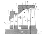
始めに図1を用いて一般的な軸流タービンのタービン段落部の基本構造を説明する。
図1に示すように、軸流タービンのタービン段落は、作動流体の流れ方向上流側(以下単に上流側と記載する)の高圧部P0と下流側の低圧部p1との間にある。タービン段落は、静止体内壁面6と内周側ダイアフラム外周面7の間に固設された静翼41、及び中心軸21周りに回転するタービンロータ15に設けられた動翼42からなり、作動流体流れ方向に複数段設けられている。各段落において、静翼41の作動流体の流れ方向下流側(以下単に下流側と記載する)に動翼42が対向する。
First, a basic structure of a turbine stage section of a general axial flow turbine will be described with reference to FIG.
As shown in FIG. 1, the turbine stage of the axial-flow turbine is located between a high-pressure part P0 on the upstream side in the flow direction of the working fluid (hereinafter simply referred to as upstream side) and a low-pressure part p1 on the downstream side. The turbine stage includes a
なお「静止体内壁面6」とは回転体であるタービンロータ15を覆う静止体(静翼を除く)の内周壁面を指し、例えば、ケーシングの内周側にダイアフラム(外周側ダイアフラム)を環状に取り付けた場合には外周側ダイアフラムの内周側壁面が「静止体内壁面6」に該当し、外周側ダイアフラムを設けない場合にはケーシングの内周側壁面が「静止体内壁面6」に該当する。また、後の説明のため、静止体内壁面6のうち、静翼41が接続された部分を「静翼外周側静止体壁面6a」、動翼42の外周側に対向する部分を「動翼外周側静止体壁面6b」と定義する。
The “stationary
上記構成により、圧力差P0−p1によって作動流体の流れ20が誘起されると、流れ20は静翼41を通過する際に増速され、またタービン周方向に偏向される。静翼41を通過して周方向の速度成分を与えられた流れは動翼42にエネルギーを与えタービンロータ15を回転させる。
With the above configuration, when the
段落入口部は段落出口部に比べて高圧で作動流体の比容積が小さいため、段落入口流路高さH1は段落出口流路高さH2よりも小さくなる。つまり、静翼41の外周部及び動翼外周側静止体壁面6aは、タービン中心軸21を含む面(子午面)とこの静翼41の外周部との交線である外径線4が前段落の動翼出口部から同じ段落を構成する動翼入口部にかけて径方向外側に傾斜しており、静翼41の部分では直線的に(あるいは単調に)作動流体の環状流路の半径が増している。即ち、静翼の入口部の半径方向高さ(段落入口流路高さ)H1に対して該静翼の出口部の半径方向高さH3が高くなっている。そのため、一般的な軸流タービンの特に長翼の段落においては、静翼41の出口外周部(外径線4上の静翼後縁部の点又は静翼外周端後縁部)3の半径R1が動翼42の入口外周部(動翼外周端前縁部)11の半径R2に対し小さい。
Since the paragraph inlet portion has a higher pressure and a smaller specific volume of the working fluid than the paragraph outlet portion, the paragraph inlet passage height H1 is smaller than the paragraph outlet passage height H2. In other words, the outer peripheral portion of the
動翼42の外周端(有効長内における外周部)に流入する流体の音速で動翼42の入口外周部11の回転周速を割った動翼外周端周速マッハ数が1.0を超えると、動翼42に流入する作動流体の動翼42に対する相対速度が超音速となる可能性がある。動翼外周端周速マッハ数が1.7を超えると、動翼42に対する作動流体の相対速度は完全に超音速となる。
The rotor blade outer peripheral speed Mach number obtained by dividing the rotational peripheral speed of the inlet
図2は動翼に対する作動流体の相対マッハ数(動翼相対流入速度)の動翼の翼長方向への変化を表したグラフである。
翼長が長く動翼外周端周速マッハ数が1.0を超える段落の動翼相対流入速度は、点線で示したように動翼の根元部周辺と先端部周辺で1.0を超え易く、動翼の根元部周辺と先端部周辺では相対速度が超音速に達した作動流体が流入する場合がある。動翼相対流入速度が超音速に達すると、動翼の上流側で流れがチョークするために動翼のスロート(周方向に隣接する動翼の最小距離)で流量を決めることができず、設計通りの作動流体の流れを実現することができなくなる。また、動翼前縁上流で形成される離脱衝撃波が翼面境界層と干渉することで大きな損失が生じる。特に動翼先端側では環帯面積が大きく作動流体の流量が大きいため、作動流体が超音速で流入することによる性能低下の割合が動翼根元付近に比べて大きい。以上のように一般的なタービン段落で長翼化を測った場合、動翼に対する作動流体の相対流入速度が超音速に達することにより、段落性能が著しく低下する恐れがある。
FIG. 2 is a graph showing changes in the relative Mach number (moving blade relative inflow velocity) of the working fluid with respect to the moving blade in the blade length direction.
The relative inflow speed of the rotor blade in the paragraph where the blade length is long and the peripheral speed Mach number of the rotor blade exceeds 1.0 tends to exceed 1.0 around the root and tip of the rotor blade as shown by the dotted line. In some cases, the working fluid having a relative velocity of supersonic velocity flows around the root portion and the tip portion of the rotor blade. When the relative inflow velocity of the blade reaches supersonic speed, the flow choke on the upstream side of the blade, so the flow rate cannot be determined by the blade throat (minimum distance between adjacent blades in the circumferential direction). The flow of the working fluid cannot be realized. Further, a large loss occurs due to the separation shock wave formed upstream of the moving blade leading edge interfering with the blade surface boundary layer. In particular, since the ring zone area is large and the flow rate of the working fluid is large on the blade tip side, the rate of performance degradation due to the working fluid flowing in at supersonic speed is large compared to the vicinity of the blade root. As described above, when the blade length is measured in a general turbine stage, the relative inflow speed of the working fluid with respect to the moving blade may reach supersonic speed, so that the stage performance may be remarkably deteriorated.
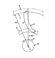
次に図3を用いて図1に示したタービン段落で動翼相対流入速度が動翼先端側で超音速になる原理を説明する。
図3において、周方向に隣接する静翼41a,41bにより形成される流路を出た作動流体は静翼出口外周部3(図1参照)において流速c1を持つ。流速c1は周方向速度成分である旋回速度ct1と軸方向速度成分である軸流速度cx1とタービン径方向外向き(紙面直交方向手前向き)の速度成分である半径速度cr1(図示せず)とからなる。一方、流速c1で静翼41a,41bを通過した流れは動翼42a,42bの外周側前縁11(図1参照)に流速c2で流入する。流速c2の旋回速度成分をct2とする。
Next, the principle that the relative inflow speed of the moving blade is supersonic at the moving blade tip side in the turbine stage shown in FIG. 1 will be described with reference to FIG.
In FIG. 3, the working fluid exiting the flow path formed by the
ここで旋回速度ct1,ct2には、静翼及び動翼の間の角運動量保存則から、静翼外周後縁半径R1と動翼外周前縁半径R2(ともに図1参照)を用いて、
R1×ct1=R2×ct2・・・(式1)
の関係が成立する。
Here, the swirl speeds ct1 and ct2 are determined from the law of conservation of angular momentum between the stationary blade and the moving blade, using the stationary blade outer peripheral edge radius R1 and the moving blade outer peripheral edge radius R2 (both see FIG. 1),
R1 × ct1 = R2 × ct2 (Formula 1)
The relationship is established.
図1に示した軸流タービンでは、
R1<R2・・・(式2)
であるため、(式1)(式2)から
ct1>ct2・・・(式3)
の関係が導かれる。
このように動翼42a,42bの入口における旋回速度ct2は静翼41a,41bの出口における旋回速度ct1に比べて小さくなる。
In the axial turbine shown in FIG.
R1 <R2 (Formula 2)
Therefore, from (Expression 1) and (Expression 2), ct1> ct2 (Expression 3)
The relationship is guided.
Thus, the turning speed ct2 at the inlet of the
一方、動翼先端側では動翼42a,42bの周速Uが大きいため、動翼42a,42bに対する作動流体の相対流入速度w2は流速c2とは逆に動翼42a,42bの回転方向と反対方向を向いた速度成分を持つこととなる。そのため流速c2の周方向速度成分ct2が小さいほど動翼相対流入速度w2は大きくなる。
On the other hand, since the peripheral speed U of the
以上の関係を考慮すると、静翼41a,41bにより与えられた旋回速度ct1は、タービン径方向外向きの速度成分を持って拡径して動翼42a,42bに流入すると、(式3)で説明したように角運動量保存則に従ってct2(<ct1)に減速するため、動翼相対流入速度w2が増大し超音速となる。すなわち、長翼化を図った場合、静翼41の外周部を通過した作動流体がタービン径方向外向きの速度成分を持つようであれば、それは動翼相対流入速度w2が超音速となってタービン段落効率が著しく低下する一因となる。
In consideration of the above relationship, when the turning speed ct1 given by the
以上を踏まえ、本発明の軸流タービンの実施の形態を以下に説明する。
図4は本発明の一実施の形態に係る軸流タービンの要部構造を表す断面図である。この図において先の各図と同様の部分に相当する箇所には同符号を付して説明を省略する。
図4に示すように、本実施の形態では、静翼外径線4が静翼41の出口部(出口外周部3)を含み且つタービン中心軸21の延伸方向(図4中の左右方向)に伸びる部分60を有するように、静翼41及び静翼外周側静止体壁面6aが形成されている。つまり、静翼出口外周部3から静翼外径線4に沿って距離dだけ上流側にある点をタービン中心軸21に沿って伸びる部分60の始端(上流端)5と定義すると、始端5から静翼出口外周部3までの区間では一定の半径R3の円筒状の環状流路が構成されている。つまり、本実施の形態では、同一のタービン段落において、
R1=R3・・・(式4)
の関係が成立する。
Based on the above, embodiments of the axial flow turbine of the present invention will be described below.
FIG. 4 is a cross-sectional view showing the main structure of the axial turbine according to the embodiment of the present invention. In this figure, portions corresponding to the same portions as those in the previous drawings are given the same reference numerals and description thereof is omitted.
As shown in FIG. 4, in the present embodiment, the stationary blade
R1 = R3 (Formula 4)
The relationship is established.
ここで、静翼外径線4の「タービン中心軸21の延伸方向に伸びる部分60」は、実質的にタービン中心軸21と平行に延在する部分であり、上記のように一定の半径R3の円筒状の環状流路を形成することから、便宜上、以下の説明において「流路同径部60」と記載する。
Here, the “
また静翼41及び静翼外周側静止体壁面6aは、静翼外径線4が作動流体流れ方向の下流側に向かってタービン半径方向外周側に傾斜した部分61を流路同径部60よりも上流側に有するように形成されている。先のタービン径方向外周側に傾斜した部分61では静翼外周側静止体壁面6aにより形成される環状流路が下流側に向かうほど拡径するので、以下の説明において、この傾斜した「部分61」を流路拡径部61と記載する。この流路拡径部61は流路同径部60に滑らかに接続している。
Further, the
それに加え、流路同径部60のタービン半径方向高さ(すなわち静翼外周後縁半径R1)は、同段落の動翼42の有効長外周部のタービン半径方向高さにほぼ等しい。本実施の形態においては、動翼42が周方向に隣接する他の動翼と連結するための連結カバー12を先端に備えているため、動翼42の有効長外周部は連結カバー12の内周面の高さ位置に定める。この場合、動翼42の有効長外周部のタービン半径方向高さは動翼外周前縁半径R2である。よって本実施の形態では、
R1=R2・・・(式5)
の関係が成立している。
なお、動翼42の有効長外周部については後に図6や図10でまた触れることにする。
In addition, the height in the turbine radial direction of the flow path same-diameter portion 60 (that is, the stationary blade outer peripheral trailing edge radius R1) is substantially equal to the height in the turbine radial direction of the effective length outer peripheral portion of the moving
R1 = R2 (Formula 5)
The relationship is established.
In addition, the effective length outer peripheral part of the moving
ここで、図4に示したタービン段落は、前段落の動翼よりも翼長の長い動翼42を有している。流路同径部60を含む段落は、動翼42の翼長が長く、具体的には、運転時に動翼42の先端部の回転周速を動翼42の先端部に流入する作動流体の音速で割った動翼先端周速マッハ数が1.0を超え得る長翼を有する段落である。
Here, the turbine stage shown in FIG. 4 has a moving
このようなタービン段落において、本実施の形態は、静翼出口付近の作動流体の環状流路をR3=R1となる円筒形状の流路としている。そのため、静翼41を通過した作動流体はタービン径方向外向きの速度成分が抑制されたタービン中心軸21にほぼ平行な流れとなる。したがって、図5に示すように本実施の形態の軸流タービンにおいて静翼41a,41bを出た流速c3の流れの旋回速度ct3は流れが拡径することで減速することがないので、ほぼ流速c3のまま動翼42a,42b間に流入することとなる。その結果、動翼相対流入速度w3を音速以下に抑制することができ、設計通りのフローパターンを実現することができる。また、動翼相対流入速度w3を音速以下に抑えることができるので、衝撃波損失を大幅に低減することができる。
In such a turbine stage, in the present embodiment, the annular flow path of the working fluid in the vicinity of the stationary blade outlet is a cylindrical flow path with R3 = R1. Therefore, the working fluid that has passed through the
また、本実施の形態においては、静翼外周後縁半径R1が動翼外周前縁半径R2にほぼ等しく設定されているため、静翼外周部近傍を通過してタービン中心軸21とほぼ平行に流れる作動流体は動翼外周部近傍に流入する。したがって、動翼42の有効長部分にバランス良く作動流体を流入させることができ、長翼化した動翼42の性能を最大限に発揮させることができる。
Further, in the present embodiment, the stationary blade outer peripheral trailing edge radius R1 is set to be substantially equal to the moving blade outer peripheral leading edge radius R2, so that it passes through the vicinity of the stationary blade outer peripheral portion and is substantially parallel to the turbine
ここで、図6は連結カバー12を設けた動翼42の先端部の拡大図である。
前述したように、動翼42の先端部には周方向に隣り合う動翼同士を連結するカバー12が設けられている。この連結カバー12と動翼42との接合部には過大な応力集中を避けるためにR部(肉盛り部)14が設けられている。この場合、動翼42の先端側からタービン径方向内周側のR部14の高さhの領域は、流体力学的に本来設計された翼形状と異なるため、作動流体のエネルギーを回転動力に変換する機能を果たす有効長に含めるのが妥当でない場合もある。そのため、動翼42の有効長外周部は、連結カバー12のタービン径方向内周側の面の高さ位置とそこからR部14の高さh分だけタービン径方向内周側の位置との間に位置することとする。つまり動翼有効長の外周部は翼根元からタービン半径方向外側に(R2−h)〜R2の間の距離にあると定義することができる。
Here, FIG. 6 is an enlarged view of the tip portion of the moving
As described above, the
したがって、流体力学的に連結カバー12の接合部のR部14のことまで考慮に入れると、動翼有効長が最大限に活かされる静翼外周側後縁半径R1は、厳密に動翼外周側前縁半径R2と等しくする必要はなく、上記(式5)は、
0≦R2−R1<h・・・(式5’)
で表される範囲に許容される。
Therefore, when the R portion 14 of the joint portion of the
0 ≦ R2−R1 <h (
Is allowed in the range represented by
また、前述したように流路同径部60がタービン中心軸21に厳密に平行である必要がないことと上記した動翼42の有効長の範囲から、上記式(4)は、
−h<R3−R1<h・・・(式4’)
で表される範囲に許容される。この場合、R3はR2との関係では(式5’)から、
0≦R2−R3<2h・・・(式6)
で表される範囲の値となる。
Further, from the fact that the flow path same-
-H <R3-R1 <h (Formula 4 ')
Is allowed in the range represented by In this case, R3 is related to R2 from (
0 ≦ R2−R3 <2h (Formula 6)
The value is in the range represented by.
つまり、本例のように動翼先端に連結カバーを備えている場合、流路同径部60の傾斜は、流路同径部60が連結カバー12の内周面の高さ位置とそこからR部14の高さhだけタービン径方向内周側の位置との間に収まる範囲での傾斜であることが好ましいが、下流側に向かって環状流路を拡径する向きに傾斜する場合、流路同径部60の始端5は、連結カバー12の内周面の高さ位置とさらに高さ2hだけタービン径方向内周側の位置との間にある場合も許容される。
That is, when the connecting blade is provided at the tip of the moving blade as in this example, the inclination of the flow path same-
ここで、図7は流路同径部60の軸方向領域(長さ)の説明図で、周方向に隣り合う静翼41a,41bの外周部を径方向外側から見た状態(連結カバー12は図示省略)を模式的に表している。
図7に示すように、静翼41a,41bの間には絞り流路102が形成されている。静翼41a,41bの間の距離が最小となる線であるスロート103は翼負圧面105と点104で交差している。この場合、作動流体は静翼41a,41b間に形成される絞り流路102に沿って最小流路幅となるスロート103まで加速され、スロート103を通過した後はほぼ慣性運動によって動翼42に流入する。
Here, FIG. 7 is an explanatory view of the axial region (length) of the flow path same-
As shown in FIG. 7, a
つまり、スロート部を通過中の作動流体は静翼に拘束されてガイドされるが、スロート部を通過した後の流れがフリーになる。本実施の形態は、このスロート部を通過した流れを流路同径部60によって半径方向の速度成分を抑えて動翼有効長に導くものであり、静翼41から出た流れの半径方向位置を大きく変化させることなく動翼42に流入させることが重要である。このことを考慮した場合、流路同径部60には絞り流路103で作動流体が最も加速されるスロート103が含まれていることが望ましい。
That is, the working fluid passing through the throat portion is guided by being restrained by the stationary blade, but the flow after passing through the throat portion becomes free. In the present embodiment, the flow that has passed through the throat portion is guided to the effective length of the moving blade by suppressing the velocity component in the radial direction by the flow path same-
すなわち、スロート103の中で最も上流側に位置するのは静翼負圧面側のスロート点104であるため、流路同径部60の始端5(図4参照)は、静翼外周部における負圧面側のスロート点104の軸方向位置かそれよりも上流側から出口外周部3にかけて延在していることが望ましい。これを具体的に図示すると、図8に示すように、流路同径部60の始端5は、点104を通りタービン中心軸21と直交する面106上、若しくはそれよりも上流側にあることが望ましい。例えば図8において下流側に向かう方向を正とするx座標をとり、始端5から面106までのx軸方向距離をαとした場合、α≧0となるように流路同径部60を確保する。これにより作動流体は、流路同径部60に達し流れの外周側が拘束された状態で絞り流路102による最大の加速力を付与されるので、静翼41を出た後の作動流体の径方向外向きの速度成分がより効果的に抑制される。
That is, since the
また前述した通り、本発明を適用したタービン段落では、出口流れの半径方向の速度成分が抑制される。複数の段落を有する本発明の軸流タービンにあって、図4〜図8で説明した特徴を最終段落に適用する場合、最終段落のさらに下流側には排気ディフューザ(図示せず)があるのみなので、通過した作動流体の半径方向の速度成分が小さくても問題はない。 Further, as described above, in the turbine stage to which the present invention is applied, the radial velocity component of the outlet flow is suppressed. In the axial turbine of the present invention having a plurality of paragraphs, when the features described in FIGS. 4 to 8 are applied to the final paragraph, there is only an exhaust diffuser (not shown) further downstream of the final paragraph. Therefore, there is no problem even if the velocity component in the radial direction of the working fluid that has passed is small.
しかし、複数の段落を有する軸流タービンでは、作動流体を膨張させ作動流体の比容積を増加させるために下流側の段落ほど翼長が大きくなる場合がある。そのため、下流側に段落が続く段落(つまり最終段以外の段落)では、段落出口で作動流体に半径方向外周向き速度成分がある方が下流側の段落に作動流体が滑らかに流入する。その意味では、本発明の特徴はタービン最終段のみに適用した場合に最も効果が大きくなる。但し、今後更なる長翼化が進んだ場合には、最終段を含めてその近傍の段落に本発明を適用した場合にも効果が期待される。また、本発明は現状の原子力発電設備等に用いられる蒸気タービンのように回転数が低く(1500rpm又は1800rpm)動翼先端に対する作動流体の相対速度が音速より遅いものに適用した場合には所望する効果は得られ難い。但し、将来的に原子力発電設備等に用いられる蒸気タービンも火力発電所の蒸気タービンの回転数(3000rpm又は3600rpm)並みの回転数となる可能性があり、その場合には本発明が適用でき、所望の効果が得られる。 However, in an axial turbine having a plurality of paragraphs, the blade length may increase in the downstream paragraph in order to expand the working fluid and increase the specific volume of the working fluid. Therefore, in a paragraph in which a paragraph continues on the downstream side (that is, a paragraph other than the final stage), the working fluid smoothly flows into the downstream paragraph when the working fluid has a radially outward velocity component at the paragraph outlet. In that sense, the features of the present invention are most effective when applied only to the turbine final stage. However, if the wings are further increased in the future, the effect is expected even when the present invention is applied to paragraphs in the vicinity including the final stage. Further, the present invention is desirable when applied to a turbine having a low rotational speed (1500 rpm or 1800 rpm) and a relative speed of the working fluid with respect to the tip of the moving blade is slower than the sonic speed, such as a steam turbine used in a current nuclear power generation facility or the like. The effect is difficult to obtain. However, there is a possibility that the steam turbine used in the nuclear power generation facility in the future will have the same rotational speed (3000 rpm or 3600 rpm) as the steam turbine of the thermal power plant, in which case the present invention can be applied, The desired effect is obtained.
図9は本発明をタービン最終段のみに適用した本発明の軸流タービンの一構成例の要部構造を表す断面図である。
図9に示すように、本例ではn段のタービン段落を有する軸流タービンにおいて、タービン最終段(第n段落)を構成する最終段静翼41nのみが、外周部に流路同径部60を有している。先の図4の例でも同様だが、本例のように動翼先端に連結カバーを設けた場合、最終段動翼42nの連結カバー12nの内周面は、最終段静翼41nの流路同径部60と同様に円筒形をなしている。つまり、タービン回転軸21を含む面との交線である外径線13nはタービン中心軸21の延伸方向に延びており、最終段動翼42nの有効長はほぼ一定となっている。
FIG. 9 is a cross-sectional view showing the main structure of a configuration example of the axial turbine according to the present invention in which the present invention is applied only to the turbine final stage.
As shown in FIG. 9, in this example, in the axial flow turbine having the n-stage turbine stage, only the final stage
最終段よりも上流側の段落の静翼は、外径線(第(n−1)段落の静翼41n−1の外径線4n−1のみ図示した)が下流側に向かって径方向外側に傾斜するように形成されている。すなわち、本構成例で最終段以外の段落では静止体内壁面6が下流側に広がる筒状に形成されている。また、最終段以外の段落の動翼の連結カバー(第(n−1)段落の動翼42n−1の連結カバー12n−1のみ図示した)の内周面は、同じ段落の静翼の外径線と同様に下流側に広がる筒状に形成されている。つまり、タービン回転軸21を含む面との交線である外径線(連結カバー12n−1の外径線13n−1のみ図示した)は下流側に向かって径方向外側に傾斜している。
The stationary blade of the upstream stage from the final stage has an outer diameter line (only the
そして、静翼の外径線の延長線は同じ段落の動翼の外径線に、その動翼の外径線の延長線は次の段落の静翼の外径線に、最終的に動翼42n−1の外径線13n−1の延長線は最終段静翼41nの外径線(流路拡径部61)にある程度滑らかに接続しており、最終段静翼41nの流路同径部60の始端5よりも上流側において、作動流体の環状流路が拡径するようになっている。このように構成することにより、作動流体の流れは流路同径部60部分に至るまでは半径方向外向きの速度成分101を持ち、各段落の入り口部に流入する際に剥離などを起こすことなく滑らかに流通し、なおかつ最終的に流路同径部60によって翼長の長い最終段動翼42nに対する相対速度が抑制されタービン段落効率を飛躍的に向上させることができる。つまり最終段よりも上流側にあって作動流体の動翼先端部に対する相対速度が音速に至る可能性の低い段落では、次の翼列に対する作動流体の導入の円滑性を重視した構成である。
Then, the extension line of the outer diameter line of the stationary blade finally moves to the outer diameter line of the moving blade of the same paragraph, and the extension line of the outer diameter line of the moving blade finally moves to the outer diameter line of the stationary blade of the next paragraph. The extension line of the
ここで、上記では動翼先端に連結カバーを設けた軸流タービンに本発明を適用した場合を例に挙げて説明したが、本発明は動翼先端が連結カバーで拘束されていない軸流タービンにも適用可能であり、同様の効果を得ることができる。動翼42に連結カバー12がなく、仮に動翼42の先端が自由端である場合には、動翼42の有効長外周部は動翼42の先端部(外周部)である。この場合、動翼42の有効長が最大限に活かされる静翼外周側後縁半径R1は、動翼外周側前縁半径R2に等しくなるため、先の(式4)及び(式5)を満たすことで動翼相対流入速度を音速以下に抑制し、なおかつ動翼42の有効長を最大限に活かすことができる。但し、(式4)(式5)に定めた関係において、製作誤差範囲の差(翼長にもよるが、例えば1〜2mm程度)は許容される。先端が連結カバーで隣接翼と連結されていない動翼42’を有する場合の本発明の軸流タービンの一構成例の要部構造を表す断面図を図10に示した。
Here, the case where the present invention is applied to an axial flow turbine in which a connecting cover is provided at the tip of a moving blade has been described as an example. However, the present invention describes an axial flow turbine in which the tip of a moving blade is not constrained by a connecting cover. The same effect can be obtained. When the moving
また、静止体内壁面6の形状についてさらに検討する。
例えば図11に示すように静翼外周側後縁半径R1が動翼外周側前縁半径R2よりも大きい場合、動翼入口11の相対流入速度w3は亜音速に抑えられるが、静翼41の外周部を通過した流れが動翼42の先端部(厳密には連結カバー12の外周部)と動翼側静止体壁面6bとの間に形成されるシール間隙16に向かって流れる。この場合、静翼41の外周部を通過した流れがシール間隙16を通過してしまいタービンロータ15を回転させるために有効に使用されない。このことから、動翼42の有効長を最大限に活かすためには、動翼先端に連結カバーを備える場合は(式5’)及び(式6)を満たすことが好ましく、動翼先端に連結カバーを設けない場合は(式5)を満たすことが好ましい。
Further, the shape of the stationary
For example, as shown in FIG. 11, when the stationary blade outer peripheral side trailing edge radius R1 is larger than the moving blade outer peripheral side leading edge radius R2, the relative inflow velocity w3 of the moving
この場合、構造上、動翼有効長外周部の外周側には動翼側静止体壁面6bとの間の所要の間隙を確保しなければならないため、静翼外周部の流路同径部60の半径方向位置を同じ段落の動翼の有効長外周部と同程度に設定する場合、流路同径部60を有する段落の動翼側静止体壁面6bは、必然的に流路同径部60よりも径方向外側に位置する。言い換えれば、このように静止体内壁面6に静翼側と動翼側とで段差を設けることにより、静翼側静止体壁面6aで整流した作動流体を効率的に動翼有効長に導くことができる。
In this case, because of the structure, it is necessary to ensure a required gap between the outer peripheral portion of the rotor blade effective length and the rotor blade side stationary
なお、以上で説明した本実施の形態の軸流タービンは種々設計変更することで動翼相対流入速度をより効果的に抑制することができる。以下にそうした効果的な構成を組み合わせた変形例を順次説明する。 In addition, the axial flow turbine of this Embodiment demonstrated above can suppress a moving blade relative inflow speed more effectively by carrying out various design changes. Hereinafter, modifications in which such effective configurations are combined will be sequentially described.
図12は静翼41の翼長方向の形状変化をスロートとピッチとの比で表したグラフである。
図4に示した実施の形態では、図12に実線で表したように、翼長方向中間部分よりも外周側の方が静翼スロートsとピッチtとの比s/tが小さくなるように静翼41にねじりを与えて形成することにより、動翼相対流入速度をさらに低減することができる。
FIG. 12 is a graph showing the shape change of the
In the embodiment shown in FIG. 4, as indicated by a solid line in FIG. 12, the ratio s / t of the stationary blade throat s to the pitch t is smaller on the outer peripheral side than the intermediate portion in the blade length direction. By forming the
ここで静翼スロートsとは、図13に示したように周方向に隣り合う静翼翼41a,41bとの間に形成される流路において流路面積が最も小さくなる部分(つまり静翼41a,41bの最小間隙部)をさす。一方ピッチtとは静翼41a,41bの周方向間隔をさす。
Here, the stationary blade throat s is a portion where the flow area is the smallest in the flow path formed between the
一般に、スロート・ピッチ比s/tは図12に点線で示したように翼内周側で小さく外周側で大きくなるように設計される。動翼先端周速マッハ数が1.0を超える場合、先の(式4)の条件成就に加え、図12に実線に示したように静翼スロート・ピッチ比s/tを外周側で小さくするように静翼を形成することで、図14に示すように、作動流体の静翼流出角a5(<a4)に小さくなる。a4は図12に点線で示した静翼形状を用いた場合の作動流体の静翼流出角である。また、静翼スロートsが絞られた分、静翼41a,41bから流出した流速c5の流れの旋回速度ct5は点線に示した静翼形状を用いた場合の作動流体の旋回速度ct4よりも大きくなる。よって、本変形例における動翼相対流入速度w4は、図12に点線に示した静翼形状を用いた場合の作動流体の動翼相対流入速度w5よりも小さくすることができる。すなわち、図4の軸流タービンに比しても、本変形例は動翼相対流入速度を低減することができる。
In general, the throat pitch ratio s / t is designed to be small on the blade inner peripheral side and larger on the outer peripheral side as shown by the dotted line in FIG. When the tip peripheral speed Mach number of the moving blade exceeds 1.0, in addition to the fulfillment of the condition (Formula 4), the stationary blade throat pitch ratio s / t is decreased on the outer peripheral side as shown by the solid line in FIG. By forming the stationary blade as described above, the working fluid becomes a stationary blade outflow angle a5 (<a4) as shown in FIG. a4 is the stationary blade outflow angle of the working fluid when the stationary blade shape shown by the dotted line in FIG. 12 is used. Further, the swirl speed ct5 of the flow at the flow velocity c5 flowing out from the
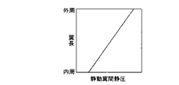
図15はタービン段落における静翼と動翼との間の静圧の翼長方向の変化を表した図である。
図15に示したように、タービン段落における静翼と動翼との間の静圧は、静翼を通過することで発生した旋回流により外周側で大きく内周側で小さくなる。そのため動翼の周速が遅い内周側では、図16に示したように外周側とは反対に動翼周速U6に対して静翼流出速度c6が大きくなり、動翼相対流入速度w6が超音速となる。
FIG. 15 is a diagram showing a change in the blade length direction of the static pressure between the stationary blade and the moving blade in the turbine stage.
As shown in FIG. 15, the static pressure between the stationary blade and the moving blade in the turbine stage is greatly increased on the outer peripheral side due to the swirling flow generated by passing through the stationary blade, and is decreased on the inner peripheral side. Therefore, on the inner peripheral side where the peripheral speed of the moving blade is slow, the stationary blade outflow speed c6 is larger than the moving blade peripheral speed U6, as shown in FIG. Supersonic speed.
図17は動翼相対流入速度(マッハ数)の翼長方向変化を表すグラフであり、一般の軸流タービンにおいて長翼化を図った場合の動翼相対流入速度の翼長方向変化を点線で示している。このグラフからも分かる通り、図15及び図16で説明した要因により、一般の軸流タービンで長翼化を図った場合、動翼の外周側だけでなく内周側においても動翼相対流入速度が音速を超える恐れがある。動翼外周側への作動流体の超音速流入は、先に説明したように静翼外周側を通過した流れのタービン径方向外向きの速度成分を抑制することにより対策される。 FIG. 17 is a graph showing the blade length direction change of the moving blade relative inflow speed (Mach number). The change in the blade length direction of the moving blade relative inflow speed when the blade length is increased in a general axial turbine is indicated by a dotted line. Show. As can be seen from this graph, when the blades are made longer with a general axial turbine due to the factors described in FIGS. 15 and 16, the relative inflow speed of the moving blades not only on the outer peripheral side but also on the inner peripheral side of the moving blades. May exceed the speed of sound. The supersonic inflow of the working fluid to the outer peripheral side of the moving blade is countered by suppressing the velocity component outward in the turbine radial direction of the flow passing through the outer peripheral side of the stationary blade as described above.
図18は動翼内周側への作動流体の超音速流入を抑制するための静翼の構成を表した概念図である。
図18において、静翼41は、翼長方向中間部の後縁2が動翼回転方向Wに突出するように湾曲して形成されている。但し、本例において静翼41は湾曲させてあるが、翼長方向中間部の後縁2が動翼回転方向Wに突出するように屈曲して形成しても良い。いずれにしても静翼41の外周側はほぼタービン径方向に延び、タービン径方向に延びる基準線50に対して静翼41の内周側部分がタービン径方向外側に向かって動翼回転方向Wに傾斜している。
FIG. 18 is a conceptual diagram showing the configuration of a stationary blade for suppressing supersonic inflow of the working fluid to the inner peripheral side of the moving blade.
In FIG. 18, the
図18のように静翼41を湾曲(又は屈曲)させることにより、静翼の内周側部分において、径方向内向きに昇圧する圧力勾配が生じ、タービン段落の静翼及び動翼の間の内周側の静圧が上昇する。これにより、図16に示した静翼出口流速c6を減少させることができ、動翼相対流入速度w6を音速以下に抑制することができる。したがって、図18に示す静翼構成を図4の実施の形態に組み合わせることにより、さらに長翼化を図っても図17に実線で示したように動翼翼長方向の全領域で動翼相対流入速度を音速以下に抑制することができる。よって、設計通りのフローパターンをより確実に実現することができ、衝撃波損失をさらに低減することができる。
By curving (or bending) the
図19は本発明の軸流タービンのさらに他の変形例の要部構造を表す断面図である。
図19に示すように、本例では、静翼外径線4が、流路同径部60よりも上流側に、流路同径部60よりもタービン半径方向外側を通り下流側に向かって径方向内側に向かう部分62を有するように静翼41及び静止体内壁面6が形成されている。なお、このタービン径方向内周側に向かう部分62では静翼外周側静止体壁面6aにより形成される環状流路が下流側に向かうほど縮小されるので、以下の説明において、この「部分62」を流路縮径部62と記載する。
FIG. 19 is a cross-sectional view showing a main part structure of still another modified example of the axial turbine according to the present invention.
As shown in FIG. 19, in the present example, the stationary blade
つまり、流路縮径部62は流路拡径部61及び流路同径部60の間に位置し、タービン径方向上向きに凸の曲率を与えられ、流路同径部60との境界部付近で変曲し、流路同径部60に滑らかに連続している。流路拡径部61に対してはそのまま連続している。流路縮径部62の最外周部の半径R4は、
R4>R3・・・(式7)
の関係を満たす。その他の構成は図4に示した構成と同様である。
That is, the flow path
R4> R3 (Formula 7)
Satisfy the relationship. Other configurations are the same as those shown in FIG.
静翼外周側を通る流れは静翼外径線4に沿って流れるため、流路縮径部62を通過する際にタービン径方向内周側に凸となる曲率を一旦与えられる。このような内周側に凸となる曲率を流れに与えることにより、タービン段落において静翼41と動翼42との間で遠心力によりタービン径方向外周側に流れが膨らもうとする作用を緩和することができる。図20に示された静翼と動翼との間の静圧分布の翼長方向変化のグラフを見て分かるように、一般的な軸流タービンの静翼と動翼との間の静圧分布は、点線で示したように翼長方向内周側から外周側に向かって高圧となる。それに対し、図19に示した構成の軸流タービンにおける静翼と動翼との間の静圧分布は、図20に実線で示したようにタービン径方向外周側の領域で静圧の上昇が抑制される。よって、図4の構成に図19の構成を組み合わせることにより、図4の構成と同様の効果が得られるとともに、静翼外周側から流出する流れの流速をより増加させ、動翼相対流入速度をさらに低減することができる。
Since the flow passing through the stationary blade outer peripheral side flows along the stationary blade
なお、以上において、静翼外径線4に流路拡径部61を設けた場合を各図の例に挙げて説明したが、静翼を通過した流れのタービン径方向外向きの速度成分を抑える限りにおいては、少なくとも静翼外周後縁部3を含む流路同径部60が設けられていれば足りる。よって、流路拡径部61は必ずしも静翼外径線4上に設ける必要はなく、場合によっては静翼入口部とその全段落の動翼出口部との間に設ける構成とすることも考えられる。この場合も同様の効果が得られる。
In the above description, the case where the flow passage diameter-expanding
また、静翼外周後縁半径R1を動翼外周前縁半径R2(又は動翼有効長外周半径)にほぼ等しくした場合を例に挙げて各図で図示説明したが、この条件は静翼を通過した流れのタービン径方向外向きの速度成分を抑える限りにおいては、必ずしも設計上満たさなければならない訳ではない。径方向外向きの速度成分を流れに与えず動翼相対流入速度を音速以下に抑える限りにおいては、静翼外径線4の少なくとも下流部に流路同径部60があれば良く、静翼外周後縁半径R1と動翼外周前縁半径R2(又は動翼有効長外周半径)の関係は必ずしも(式5’)の範囲内である必要はない。
In addition, although the case where the stationary blade outer periphery trailing edge radius R1 is substantially equal to the moving blade outer periphery leading edge radius R2 (or the effective outer periphery radius of the moving blade) has been illustrated and explained in the drawings, this condition is shown in the drawings. As long as the velocity component outward in the radial direction of the turbine is suppressed, it does not necessarily have to be satisfied by design. As long as the relative inflow speed of the moving blade is kept below the sonic speed without giving a radially outward velocity component to the flow, it is sufficient if the flow path
3 静翼出口外周部
4 静翼外径線
5 流路同径部の始端
6 静止体内壁面
6a 静翼側静止体壁面
6b 動翼側静止体壁面
11 動翼入口外周部
12 連結カバー
14 R部
21 タービン中心軸
41 静翼
41’ 静翼
42 動翼
42’ 動翼
60 流路同径部
61 流路拡径部
62 流路縮径部
103 スロート
103 スロートの動翼負圧面側の点
105 動翼負圧面
h R部の高さ
i 動翼最大厚み
R1 静翼外周後縁半径
R2 動翼外周前縁半径
s 静翼スロート
t 静翼ピッチ
3 Stator blade outlet outer
Claims (13)
前記静翼の入口部の半径方向高さに対し該静翼の出口部の半径方向高さが高い静翼は、タービン中心軸を含む面と静翼外周部との交線が静翼出口部を含んでタービン中心軸の延伸方向に伸びる部分を有するように形成され、かつ、
前記タービン中心軸の延伸方向に伸びる部分を有する段落の動翼の外周側に対向する静止体内壁面は、前記タービン中心軸の延伸方向に伸びる部分よりも径方向外側に位置しており、
動翼の翼長のうち作動流体のエネルギーを回転動力に変換するのに有効に機能する部分を動翼有効長と定義した場合、前記タービン中心軸の延伸方向に伸びる部分のタービン半径方向高さは、同じ段落の動翼の動翼有効長の外周部のタービン半径方向高さに設定されている
ことを特徴とする軸流タービン。 In the axial flow turbine having a plurality of paragraphs composed of a stationary blade and a moving blade facing the downstream side in the working fluid flow direction of the stationary blade,
A stationary blade having a radial height of an outlet portion of the stationary blade higher than a radial height of the inlet portion of the stationary blade is such that an intersection line between a surface including the turbine center axis and the outer peripheral portion of the stationary blade is Including a portion extending in the extending direction of the turbine central axis, and
The stationary body wall surface facing the outer peripheral side of the moving blade of the stage having a portion extending in the extending direction of the turbine central axis is located radially outside the portion extending in the extending direction of the turbine central axis,
When the portion of the blade length that effectively functions to convert the working fluid energy into rotational power is defined as the blade effective length, the turbine radial height of the portion extending in the extending direction of the turbine central axis Is an axial flow turbine characterized in that it is set to the height in the turbine radial direction of the outer peripheral portion of the moving blade effective length of the moving blade of the same paragraph.
前記静翼の入口部の半径方向高さに対し該静翼の出口部の半径方向高さが高い静翼は、タービン中心軸を含む面と静翼外周部との交線が静翼出口部を含んでタービン中心軸の延伸方向に伸びる部分を有するように形成され、かつ、
前記タービン中心軸の延伸方向に伸びる部分を有する段落よりも上流側の段落の静翼は、タービン中心軸を含む面と静翼外周部との交線が下流側に向かって径方向外側に傾斜するように形成されており、
前記タービン中心軸の延伸方向に伸びる部分が、最終段静翼のみに形成されている
ことを特徴とする軸流タービン。 In the axial flow turbine having a plurality of paragraphs composed of a stationary blade and a moving blade facing the downstream side in the working fluid flow direction of the stationary blade,
A stationary blade having a radial height of an outlet portion of the stationary blade higher than a radial height of the inlet portion of the stationary blade is such that an intersection line between a surface including the turbine center axis and the outer peripheral portion of the stationary blade is Including a portion extending in the extending direction of the turbine central axis, and
The stationary blade of the upstream stage with respect to the upstream side of the stage having a portion extending in the extending direction of the turbine central axis is inclined radially outward toward the downstream side of the intersection of the surface including the turbine central axis and the outer peripheral portion of the stationary blade Is formed to
The axial flow turbine characterized in that a portion extending in the extending direction of the turbine central shaft is formed only in the final stage stationary blade.
前記静翼の入口部の半径方向高さに対し該静翼の出口部の半径方向高さが高い静翼は、タービン中心軸を含む面と静翼外周部との交線が静翼出口部を含んでタービン中心軸の延伸方向に伸びる部分を有するように形成され、かつ、
前記タービン中心軸の延伸方向に伸びる部分は、周方向に隣接する静翼との距離が最小となる前記静翼外周部の負圧面側の点の軸方向位置かそれよりも上流側から延伸していることを特徴とする軸流タービン。 In the axial flow turbine having a plurality of paragraphs composed of a stationary blade and a moving blade facing the downstream side in the working fluid flow direction of the stationary blade,
A stationary blade having a radial height of an outlet portion of the stationary blade higher than a radial height of the inlet portion of the stationary blade is such that an intersection line between a surface including the turbine center axis and the outer peripheral portion of the stationary blade is Including a portion extending in the extending direction of the turbine central axis, and
The portion extending in the extending direction of the turbine central axis extends from the axial position of the point on the suction surface side of the outer peripheral portion of the stationary blade where the distance from the stationary blade adjacent in the circumferential direction is the minimum, or from the upstream side. An axial-flow turbine characterized by that.
前記静翼の入口部の半径方向高さに対し該静翼の出口部の半径方向高さが高い静翼は、タービン中心軸を含む面と静翼外周部との交線が静翼出口部を含んでタービン中心軸の延伸方向に伸びる部分を有するように形成され、かつ、
前記タービン中心軸の延伸方向に伸びる部分を含む段落は、動翼先端部の回転周速をこの動翼先端部に流入する作動流体の音速で割った動翼先端周速マッハ数が1.0を超える
ことを特徴とする軸流タービン。 In the axial flow turbine having a plurality of paragraphs composed of a stationary blade and a moving blade facing the downstream side in the working fluid flow direction of the stationary blade,
A stationary blade having a radial height of an outlet portion of the stationary blade higher than a radial height of the inlet portion of the stationary blade is such that an intersection line between a surface including the turbine center axis and the outer peripheral portion of the stationary blade is Including a portion extending in the extending direction of the turbine central axis, and
In the paragraph including the portion extending in the extending direction of the turbine central axis, the rotor blade tip peripheral speed Mach number obtained by dividing the rotational peripheral speed of the blade tip by the sound speed of the working fluid flowing into the blade tip is 1.0. An axial turbine characterized by exceeding.
Priority Applications (1)
| Application Number | Priority Date | Filing Date | Title |
|---|---|---|---|
| JP2006087699A JP4515404B2 (en) | 2005-03-31 | 2006-03-28 | Axial flow turbine |
Applications Claiming Priority (2)
| Application Number | Priority Date | Filing Date | Title |
|---|---|---|---|
| JP2005101371 | 2005-03-31 | ||
| JP2006087699A JP4515404B2 (en) | 2005-03-31 | 2006-03-28 | Axial flow turbine |
Related Child Applications (1)
| Application Number | Title | Priority Date | Filing Date |
|---|---|---|---|
| JP2007036187A Division JP4869974B2 (en) | 2005-03-31 | 2007-02-16 | Axial flow turbine |
Publications (3)
| Publication Number | Publication Date |
|---|---|
| JP2006307843A true JP2006307843A (en) | 2006-11-09 |
| JP2006307843A5 JP2006307843A5 (en) | 2007-04-05 |
| JP4515404B2 JP4515404B2 (en) | 2010-07-28 |
Family
ID=37474989
Family Applications (1)
| Application Number | Title | Priority Date | Filing Date |
|---|---|---|---|
| JP2006087699A Active JP4515404B2 (en) | 2005-03-31 | 2006-03-28 | Axial flow turbine |
Country Status (1)
| Country | Link |
|---|---|
| JP (1) | JP4515404B2 (en) |
Cited By (5)
| Publication number | Priority date | Publication date | Assignee | Title |
|---|---|---|---|---|
| CN101839148A (en) * | 2009-03-16 | 2010-09-22 | 株式会社日立制作所 | Steam turbine rotor blade and corresponding steam turbine |
| JP2011069308A (en) * | 2009-09-28 | 2011-04-07 | Hitachi Ltd | Axial flow turbine |
| JP2012149614A (en) * | 2011-01-21 | 2012-08-09 | Hitachi Ltd | Axial flow turbine |
| EP2540967A2 (en) | 2011-06-29 | 2013-01-02 | Hitachi Ltd. | Supersonic turbine moving blade and axial-flow turbine |
| JP2021509458A (en) * | 2018-01-02 | 2021-03-25 | ゼネラル・エレクトリック・カンパニイ | Controlled flow guide for turbines |
Citations (13)
| Publication number | Priority date | Publication date | Assignee | Title |
|---|---|---|---|---|
| JPH01106903A (en) * | 1987-10-21 | 1989-04-24 | Toshiba Corp | Turbine nozzle |
| JPH02169802A (en) * | 1988-12-23 | 1990-06-29 | Toshiba Corp | Turbine blade lacing wire structure |
| JPH03189304A (en) * | 1990-03-19 | 1991-08-19 | Hitachi Ltd | Stationary blade for axial-flow fluid machinery |
| JPH06323105A (en) * | 1993-05-13 | 1994-11-22 | Hitachi Ltd | Leaking and flowing passage structure for axial-flow turbo-machinery |
| JPH07233703A (en) * | 1994-02-23 | 1995-09-05 | Mitsubishi Heavy Ind Ltd | Shroud for gas turbine moving blade |
| JPH08109803A (en) * | 1994-10-13 | 1996-04-30 | Toshiba Corp | Turbine nozzle, turbine moving blade and turbine stage |
| JPH10184304A (en) * | 1996-12-27 | 1998-07-14 | Toshiba Corp | Turbine nozzle and turbine moving blade of axial flow turbine |
| JP2000248903A (en) * | 1999-02-26 | 2000-09-12 | Toshiba Corp | Axial flow turbine |
| JP2001055902A (en) * | 1999-08-18 | 2001-02-27 | Toshiba Corp | Turbine rotor blade |
| JP2003020904A (en) * | 2001-07-11 | 2003-01-24 | Toshiba Corp | Axial flow turbine blade and axial flow turbine stage |
| JP2003106106A (en) * | 2001-10-02 | 2003-04-09 | Ishikawajima Harima Heavy Ind Co Ltd | Gas turbine structure |
| JP2003269109A (en) * | 2002-03-18 | 2003-09-25 | Toshiba Corp | Steam turbine |
| JP2004232499A (en) * | 2003-01-28 | 2004-08-19 | Toshiba Corp | Turbine rotor blade and coating forming method |
-
2006
- 2006-03-28 JP JP2006087699A patent/JP4515404B2/en active Active
Patent Citations (13)
| Publication number | Priority date | Publication date | Assignee | Title |
|---|---|---|---|---|
| JPH01106903A (en) * | 1987-10-21 | 1989-04-24 | Toshiba Corp | Turbine nozzle |
| JPH02169802A (en) * | 1988-12-23 | 1990-06-29 | Toshiba Corp | Turbine blade lacing wire structure |
| JPH03189304A (en) * | 1990-03-19 | 1991-08-19 | Hitachi Ltd | Stationary blade for axial-flow fluid machinery |
| JPH06323105A (en) * | 1993-05-13 | 1994-11-22 | Hitachi Ltd | Leaking and flowing passage structure for axial-flow turbo-machinery |
| JPH07233703A (en) * | 1994-02-23 | 1995-09-05 | Mitsubishi Heavy Ind Ltd | Shroud for gas turbine moving blade |
| JPH08109803A (en) * | 1994-10-13 | 1996-04-30 | Toshiba Corp | Turbine nozzle, turbine moving blade and turbine stage |
| JPH10184304A (en) * | 1996-12-27 | 1998-07-14 | Toshiba Corp | Turbine nozzle and turbine moving blade of axial flow turbine |
| JP2000248903A (en) * | 1999-02-26 | 2000-09-12 | Toshiba Corp | Axial flow turbine |
| JP2001055902A (en) * | 1999-08-18 | 2001-02-27 | Toshiba Corp | Turbine rotor blade |
| JP2003020904A (en) * | 2001-07-11 | 2003-01-24 | Toshiba Corp | Axial flow turbine blade and axial flow turbine stage |
| JP2003106106A (en) * | 2001-10-02 | 2003-04-09 | Ishikawajima Harima Heavy Ind Co Ltd | Gas turbine structure |
| JP2003269109A (en) * | 2002-03-18 | 2003-09-25 | Toshiba Corp | Steam turbine |
| JP2004232499A (en) * | 2003-01-28 | 2004-08-19 | Toshiba Corp | Turbine rotor blade and coating forming method |
Cited By (8)
| Publication number | Priority date | Publication date | Assignee | Title |
|---|---|---|---|---|
| CN101839148A (en) * | 2009-03-16 | 2010-09-22 | 株式会社日立制作所 | Steam turbine rotor blade and corresponding steam turbine |
| JP2011069308A (en) * | 2009-09-28 | 2011-04-07 | Hitachi Ltd | Axial flow turbine |
| JP2012149614A (en) * | 2011-01-21 | 2012-08-09 | Hitachi Ltd | Axial flow turbine |
| EP2540967A2 (en) | 2011-06-29 | 2013-01-02 | Hitachi Ltd. | Supersonic turbine moving blade and axial-flow turbine |
| US9051839B2 (en) | 2011-06-29 | 2015-06-09 | Mitsubishi Hitachi Power Systems, Ltd. | Supersonic turbine moving blade and axial-flow turbine |
| EP3828387A1 (en) | 2011-06-29 | 2021-06-02 | Mitsubishi Power, Ltd. | Turbine moving blade and axial-flow turbine |
| EP3832068A1 (en) | 2011-06-29 | 2021-06-09 | Mitsubishi Power, Ltd. | Turbine moving blade and axial-flow turbine |
| JP2021509458A (en) * | 2018-01-02 | 2021-03-25 | ゼネラル・エレクトリック・カンパニイ | Controlled flow guide for turbines |
Also Published As
| Publication number | Publication date |
|---|---|
| JP4515404B2 (en) | 2010-07-28 |
Similar Documents
| Publication | Publication Date | Title |
|---|---|---|
| US7429161B2 (en) | Axial turbine | |
| JP4869974B2 (en) | Axial flow turbine | |
| JP6030853B2 (en) | Turbine blade and axial turbine | |
| WO2018179100A1 (en) | Centrifugal compressor and turbocharger | |
| US9011084B2 (en) | Steam turbine stator vane and steam turbine using the same | |
| JP2008128064A (en) | Diagonal flow turbine or radial turbine | |
| JP4515404B2 (en) | Axial flow turbine | |
| JP5023125B2 (en) | Axial flow turbine | |
| JP6268315B2 (en) | Turbine blade and steam turbine | |
| JP2009036118A (en) | Axial-flow exhaust gas turbine | |
| JP6518526B2 (en) | Axial flow turbine | |
| JP2009036112A (en) | Blade for rotary machine | |
| EP3998397A1 (en) | Steam turbine with diffuser | |
| JP2008202420A (en) | Nozzle blade and axial-flow turbine | |
| JP3927887B2 (en) | Stator blade of axial compressor | |
| JP2016079919A (en) | Moving blade and axial flow turbine | |
| KR20190116516A (en) | Gas turbine | |
| JP2005233057A (en) | Compressor for transonic fluid | |
| JP2018035676A (en) | Turbine | |
| JP6684593B2 (en) | Axial turbine | |
| JP4782625B2 (en) | Axial flow turbine | |
| JP2015175336A (en) | Turbine rotor blade and steam turbine |
Legal Events
| Date | Code | Title | Description |
|---|---|---|---|
| A521 | Request for written amendment filed |
Free format text: JAPANESE INTERMEDIATE CODE: A523 Effective date: 20070216 |
|
| A621 | Written request for application examination |
Free format text: JAPANESE INTERMEDIATE CODE: A621 Effective date: 20070216 |
|
| A977 | Report on retrieval |
Free format text: JAPANESE INTERMEDIATE CODE: A971007 Effective date: 20090814 |
|
| A131 | Notification of reasons for refusal |
Free format text: JAPANESE INTERMEDIATE CODE: A131 Effective date: 20100209 |
|
| A521 | Request for written amendment filed |
Free format text: JAPANESE INTERMEDIATE CODE: A523 Effective date: 20100412 |
|
| TRDD | Decision of grant or rejection written | ||
| A01 | Written decision to grant a patent or to grant a registration (utility model) |
Free format text: JAPANESE INTERMEDIATE CODE: A01 Effective date: 20100511 |
|
| A01 | Written decision to grant a patent or to grant a registration (utility model) |
Free format text: JAPANESE INTERMEDIATE CODE: A01 |
|
| A61 | First payment of annual fees (during grant procedure) |
Free format text: JAPANESE INTERMEDIATE CODE: A61 Effective date: 20100512 |
|
| R150 | Certificate of patent or registration of utility model |
Ref document number: 4515404 Country of ref document: JP Free format text: JAPANESE INTERMEDIATE CODE: R150 Free format text: JAPANESE INTERMEDIATE CODE: R150 |
|
| FPAY | Renewal fee payment (event date is renewal date of database) |
Free format text: PAYMENT UNTIL: 20130521 Year of fee payment: 3 |
|
| FPAY | Renewal fee payment (event date is renewal date of database) |
Free format text: PAYMENT UNTIL: 20130521 Year of fee payment: 3 |
|
| R250 | Receipt of annual fees |
Free format text: JAPANESE INTERMEDIATE CODE: R250 |
|
| S111 | Request for change of ownership or part of ownership |
Free format text: JAPANESE INTERMEDIATE CODE: R313111 |
|
| R350 | Written notification of registration of transfer |
Free format text: JAPANESE INTERMEDIATE CODE: R350 |
|
| R250 | Receipt of annual fees |
Free format text: JAPANESE INTERMEDIATE CODE: R250 |
|
| R250 | Receipt of annual fees |
Free format text: JAPANESE INTERMEDIATE CODE: R250 |
|
| R250 | Receipt of annual fees |
Free format text: JAPANESE INTERMEDIATE CODE: R250 |
|
| R250 | Receipt of annual fees |
Free format text: JAPANESE INTERMEDIATE CODE: R250 |
|
| R250 | Receipt of annual fees |
Free format text: JAPANESE INTERMEDIATE CODE: R250 |
|
| R250 | Receipt of annual fees |
Free format text: JAPANESE INTERMEDIATE CODE: R250 |
|
| S533 | Written request for registration of change of name |
Free format text: JAPANESE INTERMEDIATE CODE: R313533 |
|
| R350 | Written notification of registration of transfer |
Free format text: JAPANESE INTERMEDIATE CODE: R350 |
|
| R250 | Receipt of annual fees |
Free format text: JAPANESE INTERMEDIATE CODE: R250 |
|
| R250 | Receipt of annual fees |
Free format text: JAPANESE INTERMEDIATE CODE: R250 |
|
| R250 | Receipt of annual fees |
Free format text: JAPANESE INTERMEDIATE CODE: R250 |