JP2006305293A - Pneumatic body-acting apparatus - Google Patents
Pneumatic body-acting apparatus Download PDFInfo
- Publication number
- JP2006305293A JP2006305293A JP2005193758A JP2005193758A JP2006305293A JP 2006305293 A JP2006305293 A JP 2006305293A JP 2005193758 A JP2005193758 A JP 2005193758A JP 2005193758 A JP2005193758 A JP 2005193758A JP 2006305293 A JP2006305293 A JP 2006305293A
- Authority
- JP
- Japan
- Prior art keywords
- pressurized air
- pneumatic
- valve
- opening
- solenoid
- Prior art date
- Legal status (The legal status is an assumption and is not a legal conclusion. Google has not performed a legal analysis and makes no representation as to the accuracy of the status listed.)
- Pending
Links
Images


Classifications
-
- F—MECHANICAL ENGINEERING; LIGHTING; HEATING; WEAPONS; BLASTING
- F16—ENGINEERING ELEMENTS AND UNITS; GENERAL MEASURES FOR PRODUCING AND MAINTAINING EFFECTIVE FUNCTIONING OF MACHINES OR INSTALLATIONS; THERMAL INSULATION IN GENERAL
- F16K—VALVES; TAPS; COCKS; ACTUATING-FLOATS; DEVICES FOR VENTING OR AERATING
- F16K31/00—Actuating devices; Operating means; Releasing devices
- F16K31/02—Actuating devices; Operating means; Releasing devices electric; magnetic
- F16K31/06—Actuating devices; Operating means; Releasing devices electric; magnetic using a magnet, e.g. diaphragm valves, cutting off by means of a liquid
- F16K31/0603—Multiple-way valves
- F16K31/0624—Lift valves
- F16K31/0627—Lift valves with movable valve member positioned between seats
-
- A—HUMAN NECESSITIES
- A61—MEDICAL OR VETERINARY SCIENCE; HYGIENE
- A61H—PHYSICAL THERAPY APPARATUS, e.g. DEVICES FOR LOCATING OR STIMULATING REFLEX POINTS IN THE BODY; ARTIFICIAL RESPIRATION; MASSAGE; BATHING DEVICES FOR SPECIAL THERAPEUTIC OR HYGIENIC PURPOSES OR SPECIFIC PARTS OF THE BODY
- A61H9/00—Pneumatic or hydraulic massage
- A61H9/005—Pneumatic massage
- A61H9/0078—Pneumatic massage with intermittent or alternately inflated bladders or cuffs
-
- F—MECHANICAL ENGINEERING; LIGHTING; HEATING; WEAPONS; BLASTING
- F16—ENGINEERING ELEMENTS AND UNITS; GENERAL MEASURES FOR PRODUCING AND MAINTAINING EFFECTIVE FUNCTIONING OF MACHINES OR INSTALLATIONS; THERMAL INSULATION IN GENERAL
- F16K—VALVES; TAPS; COCKS; ACTUATING-FLOATS; DEVICES FOR VENTING OR AERATING
- F16K11/00—Multiple-way valves, e.g. mixing valves; Pipe fittings incorporating such valves
- F16K11/02—Multiple-way valves, e.g. mixing valves; Pipe fittings incorporating such valves with all movable sealing faces moving as one unit
- F16K11/04—Multiple-way valves, e.g. mixing valves; Pipe fittings incorporating such valves with all movable sealing faces moving as one unit comprising only lift valves
- F16K11/044—Multiple-way valves, e.g. mixing valves; Pipe fittings incorporating such valves with all movable sealing faces moving as one unit comprising only lift valves with movable valve members positioned between valve seats
Landscapes
- Engineering & Computer Science (AREA)
- General Engineering & Computer Science (AREA)
- Mechanical Engineering (AREA)
- Health & Medical Sciences (AREA)
- Epidemiology (AREA)
- Pain & Pain Management (AREA)
- Physical Education & Sports Medicine (AREA)
- Rehabilitation Therapy (AREA)
- Life Sciences & Earth Sciences (AREA)
- Animal Behavior & Ethology (AREA)
- General Health & Medical Sciences (AREA)
- Public Health (AREA)
- Veterinary Medicine (AREA)
- Massaging Devices (AREA)
Abstract
Description
本発明は、身体に当接して使用されて、加圧空気を供給排出されて膨張収縮することにより身体への作用を行う空圧式身体作用具に関し、特に、人間の上肢や下肢などの周りに取り付けられたり、横臥する身体の下に敷かれたりして、加圧空気の供給排出により膨張収縮してマッサージ作用を行う空圧式マッサージ具と、該空圧式マッサージ具への加圧空気源(エアポンプ)を備え、空圧式マッサージ具使用者の近くに置かれるマッサージ器本体とを有する空圧式マッサージ器に関する。 The present invention relates to a pneumatic body action tool that is used in contact with a body and performs an action on the body by supplying and discharging pressurized air and expanding and contracting, and particularly, around a human upper limb or lower limb. A pneumatic massage device that is attached or laid under a lying body and expands and contracts by supplying and discharging pressurized air to perform a massage action, and a pressurized air source (air pump) to the pneumatic massage device And a pneumatic massager having a massager body placed near the pneumatic massager user.
空圧式マッサージ器は、通常、空圧式マッサージ具が、それぞれ加圧空気を供給排出されて膨張収縮する複数の気密室を有し、マッサージ器本体が気密室の数に応じた数の三方電磁弁を備え、各電磁弁とそれに対応する気密室とがそれぞれ別のホースによって連通され、該電磁弁を介して該気密室への加圧空気供給、気密室から加圧空気排出が行われるようになっている。(特許文献1参照)
このため、使用者が装着する空気式マッサージ具と、マッサージ器本体との間には、気密室の数に応じたホースが設けられることになり、取り扱いが面倒になる。また、気密室から排気する場合に該気密室から排気される空気は、マッサージ器本体の電磁弁を通して行われるので、電磁弁までのホースにおける流路抵抗のために迅速な排気が難しい。
本発明は、このような問題を解決することを目的とする。
For this reason, a hose corresponding to the number of airtight chambers is provided between the pneumatic massager worn by the user and the massager body, which makes handling difficult. Further, when exhausting from the hermetic chamber, the air exhausted from the hermetic chamber is conducted through the electromagnetic valve of the massager body, so that rapid exhaust is difficult due to the flow path resistance in the hose to the electromagnetic valve.
The present invention aims to solve such problems.
すなわち、本発明は、
身体に当接して使用される空圧式身体作用具であって、加圧空気を供給排出されて膨張収縮することにより身体への作用を行う空圧式身体作用具と、
該空圧式身体作用具とは別に設けられ、加圧空気源を備え、該空圧式身体作用具の使用者の近くに置かれる空圧式身体作用装置本体と
を有する空圧式身体作用装置において、
該空圧式身体作用具が、
それぞれ加圧空気を供給排出される複数の気密室と、
空圧式身体作用装置本体の加圧空気源に接続可能とされた接続端を有するホースと、
該ホースと各気密室との間に接続され、ホースからの各気密室への加圧空気供給を行う電動式加圧空気配給手段と
を有することを特徴とする空圧式身体作用装置を提供する。
That is, the present invention
A pneumatic body action tool that is used in contact with the body, the pneumatic body action tool acting on the body by supplying and discharging pressurized air and expanding and contracting;
A pneumatic body effect device, provided separately from the pneumatic body effect device, having a pressurized air source and having a pneumatic body effect device body placed near a user of the pneumatic body effect device,
The pneumatic body effector is
A plurality of airtight chambers each supplied and discharged with pressurized air;
A hose having a connection end that is connectable to a pressurized air source of the pneumatic body effector body;
There is provided a pneumatic body action device, characterized in that it has an electric pressurized air distribution means connected between the hose and each hermetic chamber and supplying pressurized air from the hose to each hermetic chamber. .
この空圧式身体作用装置では、人体に対する作用を行う空圧式身体作用具に電磁弁を取り付けるようにしたので、加圧空気源から電磁弁に加圧空気を供給するために空圧式身体作用装置本体と該空圧式身体作用具との間に設ける接続ホースを単一のものとすることが可能となる。 In this pneumatic body working device, the electromagnetic valve is attached to the pneumatic body working tool that acts on the human body, so the pneumatic body working device main body is used to supply pressurized air from the pressurized air source to the electromagnetic valve. It is possible to provide a single connection hose provided between the pneumatic body working tool and the pneumatic body working tool.
具体的には、
該空圧式身体作用具が、加圧空気を供給排出されることにより膨張収縮してマッサージ作用を行う空圧式マッサージ具とされ、
該電動式加圧空気配給手段が、該ホースと各気密室との間に接続された複数の電磁弁であって、それぞれが、ホースからの気密室への加圧空気供給、気密室からの加圧空気排出を行う複数の電磁弁と
を有するものとすることができる。
In particular,
The pneumatic body action device is a pneumatic massage device that performs a massage action by expanding and contracting by supplying and discharging pressurized air,
The electric pressurized air distribution means is a plurality of solenoid valves connected between the hose and each hermetic chamber, each of which supplies pressurized air from the hose to the hermetic chamber, And a plurality of solenoid valves for discharging pressurized air.
このようにした場合、気密室から加圧空気を排出する際の気密室から該電磁弁までの距離を短くすることが出来るので、流路抵抗を小さくすることが出来る。 In this case, since the distance from the airtight chamber to the electromagnetic valve when discharging the pressurized air from the airtight chamber can be shortened, the flow path resistance can be reduced.
より具体的には、
空圧式身体作用具が、
各電磁弁に接続され、前記ホースに沿って該ホースの前記接続端まで延びて、接続端子で終端する電磁弁制御用リード線と、
該電磁弁制御用リード線の接続端子を保持し、空圧式身体作用装置本体の電磁弁制御装置からの制御信号ケーブルを受け入れて、該ケーブルと接続端子の電気接続を可能にするコネクタと
を有するようにすることができる。
More specifically,
Pneumatic body working equipment
A solenoid valve control lead wire connected to each solenoid valve, extending along the hose to the connection end of the hose and terminating at a connection terminal;
A connector for holding a connection terminal of the electromagnetic valve control lead wire, receiving a control signal cable from the electromagnetic valve control device of the pneumatic body action device body, and enabling electrical connection between the cable and the connection terminal; Can be.
本発明は、また、
身体に当接して使用される空圧式身体作用具であって、加圧空気を供給排出されて膨張収縮することにより身体への作用を行う空圧式身体作用具と、
該空圧式身体作用具とは別に設けられ、加圧空気源を備え、該空圧式身体作用具の使用者の近くに置かれる空圧式身体作用装置本体と
を有する空圧式身体作用装置において、
該空圧式身体作用具が、
それぞれ加圧空気を供給排出される複数の気密室と、
それぞれ対応する気密室に接続された複数の電磁弁であって、それぞれが、加圧源からの気密室への加圧空気供給を行う複数の電磁弁と、
該複数の電磁弁を保持し、加圧空気源からの加圧空気供給ホースに接続可能であり、加圧空気源からの加圧空気を電磁弁に供給するヘッダと、
を有することを特徴とする空圧式身体作用装置を提供する。
The present invention also provides
A pneumatic body action tool that is used in contact with the body, the pneumatic body action tool acting on the body by supplying and discharging pressurized air and expanding and contracting;
A pneumatic body effect device, provided separately from the pneumatic body effect device, having a pressurized air source and having a pneumatic body effect device body placed near a user of the pneumatic body effect device,
The pneumatic body effector is
A plurality of airtight chambers each supplied and discharged with pressurized air;
A plurality of solenoid valves each connected to a corresponding hermetic chamber, each of which is a plurality of solenoid valves for supplying pressurized air from a pressurization source to the hermetic chamber;
A header for holding the plurality of solenoid valves, connectable to a pressurized air supply hose from a pressurized air source, and supplying pressurized air from the pressurized air source to the solenoid valve;
A pneumatic body working device is provided.
この空圧式身体作用装置においても、人体に対する作用を行う空圧式身体作用具に電磁弁を取り付けるようにしたので、加圧空気源から電磁弁に加圧空気を供給するために空圧式身体作用装置本体と該空圧式身体作用具との間に設ける接続ホースを単一のものとすることが可能であり、また、気密室から加圧空気を排出する際に従来のもののように空圧式マッサージ具とマッサージ具本体との間に延びる接続ホースを通すことが無く、排気のための流路を短くすることが出来るので、該流路の抵抗を小さくすることが出来る。 Also in this pneumatic body action device, since the electromagnetic valve is attached to the pneumatic body tool that acts on the human body, the pneumatic body action device is used to supply pressurized air from the pressurized air source to the electromagnetic valve. It is possible to make a single connection hose provided between the main body and the pneumatic body action tool, and when discharging pressurized air from the hermetic chamber, a pneumatic massage tool like the conventional one Since the connecting hose extending between the body and the massage device main body is not passed and the exhaust flow path can be shortened, the resistance of the flow path can be reduced.
本発明に係る空圧式身体作用装置で用いられる上記電磁弁は、好ましくは、
筒状壁、該筒状壁の両端を閉じる第1及び第2端壁、該第1端壁を貫通する第1開口、第2端壁を貫通する第2開口、該第1及び第2端壁の間の位置で該筒状壁を貫通する第3開口を有するハウジングと、
該ハウジング内に該ハウジングと同軸状にして設けられた電磁ソレノイドと、
アーマチュア、及び、第1弁体及び第2弁体を有し、該電磁ソレノイドの作動により該アーマチュアが吸引されて該筒状壁の軸線方向で変位される可動弁であって、該第1弁体が該第1開口を開くと共に第2弁体が該第2開口を閉じて第1開口と第3開口とを連通状態とする第1位置と、該第1弁体が該第1開口を閉じると共に第2弁体が該第2開口を開いて第2及び第3開口を連通状態とする第2位置との間で変位可能とされた可動弁と、
を有し、
第2弁体が、該可動弁の変位方向において該第2開口に向うに従い半径方向外側に広がる形状となされた可撓性弁座係合部を有し、該可動弁が該第2位置になるときに、該可撓性弁座係合部が該第2開口の周りの弁座と係合することにより半径方向に拡がるように弾性変形しながら該弁座に対する所定の位置まで近づくようにしたものとし、
第1開口を加圧空気源に連通し、第2開口を気密室に連通し、第3開口を大気に連通するようにする。
The solenoid valve used in the pneumatic body action device according to the present invention is preferably,
A cylindrical wall, first and second end walls closing both ends of the cylindrical wall, a first opening penetrating the first end wall, a second opening penetrating the second end wall, the first and second ends A housing having a third opening extending through the cylindrical wall at a position between the walls;
An electromagnetic solenoid provided coaxially with the housing in the housing;
An armature, and a movable valve having a first valve body and a second valve body, wherein the armature is attracted by the operation of the electromagnetic solenoid and displaced in the axial direction of the cylindrical wall. A first position where the body opens the first opening and the second valve body closes the second opening to bring the first opening and the third opening into communication; and the first valve body opens the first opening. A movable valve that is displaceable between a second position that is closed and the second valve body opens the second opening and communicates the second and third openings;
Have
The second valve body has a flexible valve seat engaging portion configured to expand outward in the radial direction toward the second opening in the displacement direction of the movable valve, and the movable valve is in the second position. The flexible valve seat engaging portion is elastically deformed so as to expand radially by engaging with the valve seat around the second opening so as to approach a predetermined position with respect to the valve seat. And
The first opening communicates with the pressurized air source, the second opening communicates with the airtight chamber, and the third opening communicates with the atmosphere.
この電磁弁では、可動弁が第1位置とされたときには、加圧空気が第1開口及び第3開口を通して気密室に供給されて、空圧式身体作用具を膨張させ、同可動弁が第2位置とされたときには、加圧空気の供給は遮断されて、気密室から加圧空気が第3及び第2開口を通して外部へ排出され、空気式身体作用具が収縮する。 In this electromagnetic valve, when the movable valve is set to the first position, pressurized air is supplied to the hermetic chamber through the first opening and the third opening to inflate the pneumatic body effector, and the movable valve is in the second position. When the position is set, the supply of pressurized air is cut off, the pressurized air is discharged from the hermetic chamber through the third and second openings, and the pneumatic body effector contracts.
この電磁弁においては、第2弁体が上記の如き可撓性弁座係合部を有するので、弁座係合部の弁座に対する圧縮代を大きくすることが出来る。 In this solenoid valve, since the second valve body has the flexible valve seat engaging portion as described above, the compression allowance of the valve seat engaging portion with respect to the valve seat can be increased.
すなわち、弁座係合部は、弁座に係合するように全体として環状とされ、その半径方向での断面は、通常は、半円状としたものが多い。その様なものでは、弁座係合部が弁座と係合するときには、弁座に対する押圧力によりある程度は弾性変形するが、圧縮代すなわち、弁座に押圧されて弾性変形する大きさを余り大きくすることが出来ない。 That is, the valve seat engaging portion is generally annular so as to engage with the valve seat, and the radial cross section is usually semicircular. In such a case, when the valve seat engaging portion engages with the valve seat, it is elastically deformed to some extent by the pressing force against the valve seat, but the compression margin, that is, the size that is elastically deformed by being pressed by the valve seat is excessive. I can't make it bigger.
気密室への加圧空気の供給を確実適正に行うためには、排気口としての第2開口を確実に閉止する必要があり、このため、弁座に対する弁座係合部の押圧力与えるための電磁ソレノイドをそれなりに大きなものとする必要があり、前述した空圧式身体作用具などへの装着のために小型化を計るには支障となる。 In order to reliably and properly supply pressurized air to the hermetic chamber, it is necessary to close the second opening as the exhaust port reliably, and in order to apply a pressing force of the valve seat engaging portion to the valve seat. Therefore, it is necessary to increase the size of the electromagnetic solenoid. Therefore, it is difficult to reduce the size of the electromagnetic solenoid for mounting on the pneumatic body working tool.
これに対して、本発明においては弁座係合部の圧縮代を大きくすることが出来る、換言すれば、小さな押圧力で弁座係合部の弁座に対する圧縮変形を伴う係合を可能とすることができ、弁座との適正な密封係合が可能となる。このため、電磁ソレノイドを小型軽量のものとすることができる。 On the other hand, in the present invention, the compression allowance of the valve seat engaging portion can be increased. In other words, the valve seat engaging portion can be engaged with the valve seat with compression deformation with a small pressing force. And a proper sealing engagement with the valve seat is possible. For this reason, an electromagnetic solenoid can be made small and light.
また、電磁ソレノイドをハウジング内に収納したので、この点でも、当該電磁弁のサイズを小型化することができる。 In addition, since the electromagnetic solenoid is housed in the housing, the size of the electromagnetic valve can be reduced in this respect as well.
更に、この電磁弁においては、それが作動されるときに、電磁ソレノイド及び可動弁が収納されているハウジング内を加圧空気が流れるので、該電磁弁の強制冷却が行われ、また、アーマチュアの衝突音の外部への漏れを抑えることができる。 Furthermore, in this solenoid valve, when it is actuated, pressurized air flows through the housing in which the solenoid solenoid and the movable valve are housed, so that the solenoid valve is forcibly cooled, and the armature Leakage of collision sound to the outside can be suppressed.
すなわち、この電磁弁は、人体に装着したりして用いられる空圧式身体作用具に適したものとなる。 That is, this electromagnetic valve is suitable for a pneumatic body action tool used by being mounted on a human body.
電磁弁は、より具体的には、
可動弁を第2位置に向けて付勢するバネ部材を有し、
可動弁が、電磁ソレノイドの軸線に沿う貫通孔を貫通して延びるロッドを有し、
アーマチュアが、電磁ソレノイドよりも第1弁体側に固定され、該電磁ソレノイドが通電されたときに、電磁ソレノイドの端面に吸着係合されて、可動弁を該第1位置とする
ようにすることができる。
More specifically, the solenoid valve
A spring member for biasing the movable valve toward the second position;
The movable valve has a rod extending through a through hole along the axis of the electromagnetic solenoid;
The armature is fixed to the first valve body side of the electromagnetic solenoid, and when the electromagnetic solenoid is energized, the armature is attracted and engaged with the end face of the electromagnetic solenoid so that the movable valve is in the first position. it can.
すなわち、電磁ソレノイドが作動してアーマチュアが吸引された場合、該アーマチュアが電磁ソレノイドの端面に係合されないで、隙間の開いた状態で止まった場合、アーマチュアに対する電磁ソレノイドの磁気吸着力は最大とはならず、このため、可動弁が反力により押し戻される可能性がある。すなわち、アーマチュアは、可動弁が第1位置にされて第2弁体が弁座と係合する状態となった状態で、電磁ソレノイドの端面に係合するようになることが望まれる。しかし、アーマチュアや可動弁体などの組立による製造誤差の集積などで、アーマチュアをその様な状態にすることは難しい。このような場合、通常の方法では、電磁ソレノイドを大型のものとしてアーマチュアへの磁気吸引力を大きくし、第2弁体の弁座係合部の弁座への圧縮代を大きくすることにより製作誤差の集積を吸収するようにせざるを得ない。
これに対し、第2弁体の弁座係合部を前述の如くすれば、電磁ソレノイドを大きくせずに、可動弁が第1位置となったときにアーマチュアが電磁ソレノイドの端面に係合するようにすることが出来る。
That is, when the armature is attracted by actuating the electromagnetic solenoid, if the armature is not engaged with the end face of the electromagnetic solenoid and stops in a state where a gap is opened, the magnetic adsorption force of the electromagnetic solenoid to the armature is the maximum Therefore, there is a possibility that the movable valve is pushed back by the reaction force. That is, the armature is desirably engaged with the end face of the electromagnetic solenoid in a state where the movable valve is in the first position and the second valve body is engaged with the valve seat. However, it is difficult to make the armature in such a state due to accumulation of manufacturing errors due to assembly of the armature and the movable valve body. In such a case, the normal method is to increase the magnetic attraction force to the armature with a large electromagnetic solenoid and increase the compression allowance of the valve seat engaging portion of the second valve body to the valve seat. It is necessary to absorb the accumulation of errors.
On the other hand, if the valve seat engaging portion of the second valve body is as described above, the armature is engaged with the end face of the electromagnetic solenoid when the movable valve is in the first position without enlarging the electromagnetic solenoid. You can do that.
本発明に係る空圧式身体作用装置は、以上のように構成されるので、空圧式身体作用具と空圧式身体作用装置本体の加圧空気源とを多数のホースでつなぐ必要はない。また、電磁弁に排気機能を持たせた場合には、気密室から電磁弁までの排気のための流路抵抗を少なくすることができるので、迅速な排気が可能となる。また、電磁弁を上述の如き構成のものとすることにより、空圧式身体作用具を軽量小型で且つ操作音の小さいものとして使用者が快適に使用することを可能とする。 Since the pneumatic body working device according to the present invention is configured as described above, it is not necessary to connect the pneumatic body working tool and the pressurized air source of the pneumatic body working device main body with a large number of hoses. Further, when the solenoid valve is provided with an exhaust function, the flow resistance for exhaust from the hermetic chamber to the solenoid valve can be reduced, so that quick exhaust is possible. In addition, by configuring the solenoid valve as described above, the pneumatic body effector can be comfortably used by the user as being lightweight and compact and having low operation sound.
以下、本発明に係る空圧式マッサージ器に適用した実施形態を、添付図面に基づき説明する。 Hereinafter, an embodiment applied to the pneumatic massager according to the present invention will be described with reference to the accompanying drawings.
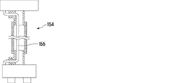
図1は、第1の実施形態に係る空圧式マッサージ器10の概要を示す。すなわち、この空圧式マッサージ器10は、使用者の左右の下肢の周りに装着される一対の空圧式マッサージ具12と、該空圧式マッサージ具の装着者の近くの床などの上に置かれるマッサージ器本体14とを有する。
FIG. 1 shows an outline of a
空圧式マッサージ具12は、その内部が複数の気密室16,18,20,22に分けられており、加圧空気を該気密室にそれぞれ供給排出することにより膨張収縮して、使用者へのマッサージ効果を奏するものである。図1の、特に右側の空圧式マッサージ具12に示されているように、空圧式マッサージ具の表面には、マッサージ器本体14の加圧空気源に接続可能とされた接続端(図で見て下端)を有するホース21と、該ホース21と各気密室16,18,20,22との間に接続された複数の電磁弁24,26,28,30とが設けられており、各電磁弁は、対応する気密室に対するホース21からの加圧空気の供給、加圧空気の保持、該気密室からの加圧空気の排出を行うようにされている。各電磁弁24,26,28,30からは、電磁弁制御用リード線24´,26´,28´,30´がホース21に沿って該ホース21の加圧源との接続端まで延び、制御信号受信端子(図示せず)で終端している。図示の例では、ホース21の接続端と電磁弁制御用リード線の制御信号受信端子とは、接続ユニット31にまとめて保持されている。図1の左側のマッサージ具12に示されているように、該マッサージ具12には、ホース21及び電磁弁24,26,28,30を覆い、外側から見えないようにするカバー32が取り付けられているようにされており、図1の右側の空圧式マッサージ器では、気密室16,18,20,22、ホース21、電磁弁24,26,28,30、及び、電磁弁制御用リード線24´,26´,28´,30´の関係を明瞭にするために、カバー32は示されていない。
The interior of the
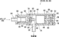
図3に示すように、電磁弁24,26,28,30は、筒状のハウジング42と、該ハウジングに設けられた電磁ソレノイド44と、ハウジング42内に設けられ該電磁ソレノイドの作動によってハウジングの軸線方向で変位する可動弁46とを有している。ハウジング42は、筒状壁48、第1端壁50、及び、第2端壁52を有している。第1端壁50には第1開口54、第2端壁52には第2開口56、筒状壁48には第3開口58が、それぞれを貫通するように設けられている。図示の例では、ハウジング42の第1端壁50に逆止弁60が取り付けられており、第1開口54は該逆止弁60を介してポンプに連通されるようになされている。すなわち、該逆止弁60は、ハウジング42に同軸状に連結された筒状ハウジング62と、該筒状ハウジング62の端壁に設けられたポンプ連通開口64に同軸状にして取り付けられたゴムなどの可撓性材からなる円錐状逆止弁部材66とを有している。
As shown in FIG. 3, the
第1開口54は、該逆止弁60を介してマッサージ器のポンプに連通され、第3開口58はポンプからの加圧空気の供給排出を受けてマッサージ器の膨張収縮を行うための気密室に連通されており、第2開口56は大気に連通されている。
The
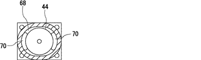
ハウジング42には、筒状壁48の内面に環状のコイル支持壁68が形成されており、電磁ソレノイド44がハウジング42に対して同軸状にして固定されている。図4に示すように、コイル支持壁68には、一対の通気口70が貫通するように設けられている。
In the
可動弁46は、該電磁ソレノイドの軸線に沿う貫通孔を貫通して延びるロッド72と、電磁ソレノイド44よりも第1開口54側で該ロッド72に固定された円盤状で鉄などの磁性材料から形成されるアーマチュア74と、ロッド72の両端に設けられた第1弁体76及び第2弁体78とから構成されている。第1弁体76は、ロッド72の端部に嵌合されて左端にフランジ80を有する筒状の弁体保持材82と、フランジ80の周りに嵌合されたゴムなどの可撓性材料からなる全体として円盤状の弁部材84とからなる。弁部材84は、第1開口54に対向する面に環状に突出した、半径方向断面がほぼ半円形の弁座係合部86を有している。第2弁体78は、第1弁体76の弁体保持材82と同様の弁体保持体88を備えるが、バネ受け部89が設けられており、第2端壁52との間に圧縮バネ90を保持し、可動弁46を第1端壁に向けて付勢している。第2弁体78は、また、第1弁体76と同様の弁部材92を備えるが、第2端壁52に対向する面に設けられる弁座係合部94が、第2端壁52に向うに従い半径方向外側に広がる円錐形状とされている。
The
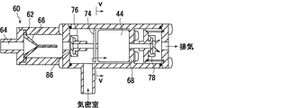
電磁弁24,26,28,30は、以上のような構成を有しており、電磁ソレノイド44が通電されていないときには、図5に示すように、可動弁46が圧縮バネ90により押圧されて、第1弁体76の弁座係合部86が第1端壁50に押圧されて第1開口54を閉じ、第2弁体78が第2端壁52から離れて第2開口56を開いた状態とされる。従って、このときはポンプからの加圧空気の供給は停止され、マッサージ器の気密室にあった加圧空気は第3開口58及び第2開口56を介して排気される状態にある。
The
これに対して電磁ソレノイド44が通電されると、それにより発生する磁力によりアーマチュア74は電磁ソレノイド44の端面に吸着され、可動弁46を第2端壁に向けて動かし、図3に示す状態とする。この状態では、第2弁体78の環状の弁座係合部94が第2開口56の周りの第2端壁52内面(すなわち弁座)に弾性変形しながら押圧されて第2開口56を閉じ、第1弁体76が第1端壁50から離れて第1開口54が開いた状態とされる。従って、このときはポンプからの加圧空気の供給は第1開口54及び第3開口58を介してマッサージ器の気密室に供給され。
On the other hand, when the
電磁ソレノイド44への通電を周期的に行うことにより、可動弁46は往復動され、マッサージ器の気密室への加圧空気の供給排気が周期的に行われる。逆止弁部材60は気密室から加圧空気がポンプ側に逆流するのを防止する。
By periodically energizing the
マッサージ器本体14は、加圧空気源としてのエアポンプ148と、該エアポンプからの加圧空気の脈動を低減するタンク150と、電磁弁24,26,28,30を制御するための制御回路152と、を有している。
The
マッサージ器本体14と各空圧式マッサージ具12とは、それぞれ、接続ホース154(図1には、右側の空圧式マッサージ具12用の接続ホースのみを示している)によって接続されており、該ホースを通して加圧空気が空圧式マッサージ具のホース21に供給されるようになっている。また、制御回路152からの電磁弁制御信号は、図2に示すように、該接続ホース内を通された制御信号ケーブル155を介して、制御弁制御用リード線に送られる。
The
図6は、空圧式マッサージ具の別の実施形態を示している。
すなわち、この空圧式マッサージ具では、加圧源に連通されるヘッダ156と、該ヘッダに連通され、それぞれが、対応する気密室16´,18´,20´,22´に連通された電磁弁158,160,162,164であって、それぞれが、気密室への加圧空気供給、加圧空気保持、気密室からの加圧空気排出を行う複数の電磁弁158,160,162,164と、を有する。該電磁弁は、前述した電磁弁24,26,28,30と実質的に同じ構造のものとすることができる。各電磁弁は、空圧式マッサージ具の表面に取り付けられたホース158´,160´,162´,164´を介して各気密室16´,18´,20´,22´に連通されている。ヘッダ156は、第1の実施形態の接続ホース154と同様の接続ホース(図示せず)により接続され、マッサージ器本体の制御回路からの制御信号に基づき電磁弁が制御され、各気密室の加圧空気供給・排気が行われる。
FIG. 6 shows another embodiment of the pneumatic massage device.
That is, in this pneumatic massage device, a
以上、本件発明に係るマッサージ装置の実施形態を説明したが、本発明はこれに限定されるものではない。例えば、マッサージ具は体に装着されるものに限られるものではなく、例えば、特公昭60−50459号に開示されているマット式のマッサージ具としたり、、実公告平3−54735号に開示の「床擦れ防止装置」として用いることが可能である。また、図示の例では、接続ホース154を用いる場合を示したが、ホース21と電磁弁制御用リード線とを、接続ホース154に相当する長さだけ延ばして接続ユニット31によりまとめて保持して、該接続端子31をマッサージ器本体14に直接接続するようにすることもできる。また、電磁弁の第1弁体76を、第2弁体78と同じような円錐形の弁座係合部を有するものとしたり、逆に第2弁体78を第1弁体76と同様に半径断面が半円形のものとすることもできる。
As mentioned above, although embodiment of the massage apparatus which concerns on this invention was described, this invention is not limited to this. For example, the massage device is not limited to the one attached to the body. For example, the massage device is a mat type massage device disclosed in Japanese Patent Publication No. 60-50459, or disclosed in Japanese Utility Model Publication No. 3-54735. It can be used as a “floor rub prevention device”. In the illustrated example, the
10 マッサージ器(空圧式身体作用装置)
12 空圧式マッサージ具(空圧式身体作用具)
14 マッサージ器本体(空圧式身体作用装置本体)
16,18,20,22 気密室
16´,18´,20´,22´ 気密室
21 ホース
24,26,28,30 電磁弁(加圧空気配給手段)
24´,26´,28´,30´ 電磁弁制御用リード線
31 接続ユニット
32 カバー
42 ハウジング
44 電磁ソレノイド
46 可動弁
48 筒状壁
50 第1端壁
52 第2端壁
54 第1開口
56 第2開口
58 第3開口
60 逆止弁筒状
62 ハウジング
64 ポンプ連通開口
66 円錐状逆止弁部材
68 コイル支持壁
70 通気口
72 ロッド
74 アーマチュア
76 第1弁体
78 第2弁体
80 フランジ
82 弁体保持材
84 弁部材
86 弁座係合部
88 弁体保持体
89 バネ受け部
90 圧縮バネ
92 弁部材
94 弁座係合部
148 加圧空気源(エアポンプ)
150 タンク
152 制御回路
154 接続ホース
155 制御信号ケーブル
156 ヘッダ
158,160,162,164 電磁弁
158´,160´,162´,164´ ホース
10 Massager (pneumatic body action device)
12 Pneumatic massager (pneumatic body effector)
14 Massage device (pneumatic body action device)
16, 18, 20, 22 Airtight chamber 16 ', 18', 20 ', 22'
24 ', 26', 28 ', 30' Electromagnetic valve
89 Spring receiving part
90
150
Claims (6)
該空圧式身体作用具とは別に設けられ、加圧空気源を備え、該空圧式身体作用具の使用者の近くに置かれる空圧式身体作用装置本体と
を有する空圧式身体作用装置において、
該空圧式身体作用具が、
それぞれ加圧空気を供給排出される複数の気密室と、
空圧式身体作用装置本体の加圧空気源に接続可能とされた接続端を有するホースと、
該ホースと各気密室との間に接続され、ホースからの各気密室への加圧空気供給を行う電動式加圧空気配給手段と
を有することを特徴とする空圧式身体作用装置。 A pneumatic body action tool that is used in contact with the body, the pneumatic body action tool acting on the body by supplying and discharging pressurized air and expanding and contracting;
A pneumatic body effect device, provided separately from the pneumatic body effect device, having a pressurized air source and having a pneumatic body effect device body placed near a user of the pneumatic body effect device,
The pneumatic body effector is
A plurality of airtight chambers each supplied and discharged with pressurized air;
A hose having a connection end that is connectable to a pressurized air source of the pneumatic body effector body;
A pneumatic body action device comprising: an electric pressurized air distributing means connected between the hose and each hermetic chamber for supplying pressurized air from the hose to each hermetic chamber.
該電動式加圧空気配給手段が、該ホースと各気密室との間に接続された複数の電磁弁であって、それぞれが、ホースからの気密室への加圧空気供給、気密室からの加圧空気排出を行う複数の電磁弁と
を有することを特徴とする空圧式身体作用装置。 The pneumatic body action device is a pneumatic massage device that performs a massage action by expanding and contracting by supplying and discharging pressurized air,
The electric pressurized air distribution means is a plurality of solenoid valves connected between the hose and each hermetic chamber, each of which supplies pressurized air from the hose to the hermetic chamber, And a plurality of solenoid valves for discharging pressurized air.
各電磁弁に接続され、該ホースに沿って該ホースの該接続端まで延びて、接続端子で終端する電磁弁制御用リード線と、
該電磁弁制御用リード線の接続端子を保持し、マッサージ器本体の電磁弁制御装置からの制御信号ケーブルを受け入れて、該ケーブルと接続端子の電気接続を可能にするコネクタと
を有することを特徴とする請求項2に記載の空圧式身体作用装置。 The pneumatic massage device is
A solenoid valve control lead wire connected to each solenoid valve, extending along the hose to the connection end of the hose and terminating at a connection terminal;
A connector that holds the connection terminal of the electromagnetic valve control lead wire, receives a control signal cable from the electromagnetic valve control device of the massager body, and enables electrical connection between the cable and the connection terminal. The pneumatic body action device according to claim 2.
該空圧式身体作用具とは別に設けられ、加圧空気源を備え、該空圧式身体作用具の使用者の近くに置かれる空圧式身体作用装置本体と
を有する空圧式身体作用装置において、
該空圧式身体作用具が、
それぞれ加圧空気を供給排出される複数の気密室と、
それぞれ対応する気密室に接続された複数の電磁弁であって、それぞれが、加圧源からの気密室への加圧空気供給を行う複数の電磁弁と、
該複数の電磁弁を保持し、加圧空気源からの加圧空気供給ホースに接続可能であり、加圧空気源からの加圧空気を電磁弁に供給するヘッダと、
を有することを特徴とする空圧式身体作用装置。 A pneumatic body action tool that is used in contact with the body, the pneumatic body action tool acting on the body by supplying and discharging pressurized air and expanding and contracting;
A pneumatic body effect device, provided separately from the pneumatic body effect device, having a pressurized air source and having a pneumatic body effect device body placed near a user of the pneumatic body effect device,
The pneumatic body effector is
A plurality of airtight chambers each supplied and discharged with pressurized air;
A plurality of solenoid valves each connected to a corresponding hermetic chamber, each of which is a plurality of solenoid valves for supplying pressurized air from a pressurization source to the hermetic chamber;
A header for holding the plurality of solenoid valves, connectable to a pressurized air supply hose from a pressurized air source, and supplying pressurized air from the pressurized air source to the solenoid valve;
A pneumatic body action device characterized by comprising:
筒状壁、該筒状壁の両端を閉じる第1及び第2端壁、該第1端壁を貫通する第1開口、第2端壁を貫通する第2開口、該第1及び第2端壁の間の位置で該筒状壁を貫通する第3開口を有するハウジングと、
該ハウジング内に該ハウジングと同軸状にして設けられた電磁ソレノイドと、
アーマチュア、及び、第1弁体及び第2弁体を有し、該電磁ソレノイドの作動により該アーマチュアが吸引されて該筒状壁の軸線方向で変位される可動弁であって、該第1弁体が該第1開口を開くと共に該第2弁体が該第2開口を閉じて該第1開口と該第3開口とを連通状態とする第1位置と、該第1弁体が該第1開口を閉じると共に該第2弁体が該第2開口を開いて該第2及び該第3開口を連通状態とする第2位置との間で変位可能とされた可動弁と、
を有し、
第2弁体が、該可動弁の変位方向において該第2開口に向うに従い半径方向外側に広がる形状となされた可撓性弁座係合部を有し、該可動弁が該第2位置になるときに、該可動性弁座係合部が該第2開口の周りの弁座と係合することにより半径方向に拡がるように弾性変形しながら該弁座に対する所定の位置まで近づくようなものとし、
第1開口を加圧空気源に連通し、第2開口を大気に連通し、第3開口を気密室に連通するようにした
ことを特徴とする請求項2乃至4のいずれかに記載の空圧式身体作用装置。 The solenoid valve
A cylindrical wall, first and second end walls closing both ends of the cylindrical wall, a first opening penetrating the first end wall, a second opening penetrating the second end wall, the first and second ends A housing having a third opening extending through the cylindrical wall at a position between the walls;
An electromagnetic solenoid provided coaxially with the housing in the housing;
An armature, and a movable valve having a first valve body and a second valve body, wherein the armature is attracted by the operation of the electromagnetic solenoid and displaced in the axial direction of the cylindrical wall. A first position in which the body opens the first opening and the second valve body closes the second opening so that the first opening and the third opening are in communication with each other; and A movable valve that is displaceable between a second position that closes one opening and the second valve body opens the second opening to bring the second and third openings into communication;
Have
The second valve body has a flexible valve seat engaging portion configured to expand outward in the radial direction toward the second opening in the displacement direction of the movable valve, and the movable valve is in the second position. When the movable valve seat engaging portion engages with the valve seat around the second opening, the movable valve seat engaging portion is elastically deformed so as to expand in the radial direction and approaches a predetermined position with respect to the valve seat. age,
5. The air according to claim 2, wherein the first opening communicates with a pressurized air source, the second opening communicates with the atmosphere, and the third opening communicates with the hermetic chamber. Pressure body action device.
該可動弁が、該電磁ソレノイドの軸線に沿う貫通孔を貫通して延びるロッドを有し、
該アーマチュアが、該電磁ソレノイドよりも該第1弁体側に固定され、該電磁ソレノイドが通電されたときに、該電磁ソレノイドの端面に吸着係合されて、該可動弁を該第1位置とする
ことを特徴とする請求項5に記載の空圧式身体作用装置。
A spring member for biasing the movable valve toward the second position;
The movable valve has a rod extending through a through hole along the axis of the electromagnetic solenoid;
The armature is fixed to the first valve body side with respect to the electromagnetic solenoid, and when the electromagnetic solenoid is energized, it is attracted and engaged with the end face of the electromagnetic solenoid, and the movable valve is set to the first position. The pneumatic body effect device according to claim 5.
Priority Applications (4)
| Application Number | Priority Date | Filing Date | Title |
|---|---|---|---|
| JP2005193758A JP2006305293A (en) | 2005-03-31 | 2005-07-01 | Pneumatic body-acting apparatus |
| US11/887,442 US20090018474A1 (en) | 2005-03-31 | 2006-03-29 | Pneumatic Body Treating Apparatus |
| EP06730363A EP1864639A1 (en) | 2005-03-31 | 2006-03-29 | Pneumatic body acting apparatus |
| PCT/JP2006/306415 WO2006106708A1 (en) | 2005-03-31 | 2006-03-29 | Pneumatic body acting apparatus |
Applications Claiming Priority (2)
| Application Number | Priority Date | Filing Date | Title |
|---|---|---|---|
| JP2005103081 | 2005-03-31 | ||
| JP2005193758A JP2006305293A (en) | 2005-03-31 | 2005-07-01 | Pneumatic body-acting apparatus |
Publications (2)
| Publication Number | Publication Date |
|---|---|
| JP2006305293A true JP2006305293A (en) | 2006-11-09 |
| JP2006305293A5 JP2006305293A5 (en) | 2008-01-31 |
Family
ID=37073272
Family Applications (1)
| Application Number | Title | Priority Date | Filing Date |
|---|---|---|---|
| JP2005193758A Pending JP2006305293A (en) | 2005-03-31 | 2005-07-01 | Pneumatic body-acting apparatus |
Country Status (4)
| Country | Link |
|---|---|
| US (1) | US20090018474A1 (en) |
| EP (1) | EP1864639A1 (en) |
| JP (1) | JP2006305293A (en) |
| WO (1) | WO2006106708A1 (en) |
Families Citing this family (11)
| Publication number | Priority date | Publication date | Assignee | Title |
|---|---|---|---|---|
| GB0307097D0 (en) | 2003-03-27 | 2003-04-30 | Bristol Myers Squibb Co | Compression device for the limb |
| ATE397912T1 (en) * | 2004-10-11 | 2008-07-15 | Smm Medical Ab | ELECTROACTIVE COMPRESSION BANDAGE |
| GB0423410D0 (en) * | 2004-10-21 | 2004-11-24 | Bristol Myers Squibb Co | Compression device for the limb |
| TWI378791B (en) * | 2005-06-08 | 2012-12-11 | Convatec Technologies Inc | A cuff for providing compression to a limb, a channel for use in a compression device and use of a separating means in the manufacture of the cuff and the channel |
| WO2007079777A1 (en) | 2006-01-13 | 2007-07-19 | Smm Medical Ab | Device, system and method for compression treatment of a body part |
| GB0601454D0 (en) * | 2006-01-24 | 2006-03-08 | Bristol Myers Squibb Co | A proximity detection apparatus |
| GB0601451D0 (en) | 2006-01-24 | 2006-03-08 | Bristol Myers Squibb Co | Control unit assembly |
| JP5006619B2 (en) * | 2006-06-29 | 2012-08-22 | 日東工器株式会社 | Solenoid valve and pneumatic massage device |
| JP4949754B2 (en) * | 2006-07-03 | 2012-06-13 | 日東工器株式会社 | Pneumatic massage device |
| US20150057585A1 (en) * | 2013-08-20 | 2015-02-26 | Covidien Lp | Compression device having compliance tracking |
| DE102017213736B3 (en) * | 2017-08-08 | 2018-10-25 | Conti Temic Microelectronic Gmbh | Pneumatic valve |
Family Cites Families (15)
| Publication number | Priority date | Publication date | Assignee | Title |
|---|---|---|---|---|
| US2196798A (en) * | 1936-06-15 | 1940-04-09 | Horstmann Frederick Otto | Tap or valve |
| JPS472526U (en) * | 1971-01-29 | 1972-08-29 | ||
| JPS5941739B2 (en) * | 1975-01-17 | 1984-10-09 | リチヤ−ド ロ−タ ニコラス | A blood circulation promoting device that uses fluid pressure to treat the human body from the outside. |
| JPS5512632Y2 (en) * | 1975-03-14 | 1980-03-19 | ||
| JPS5728965U (en) * | 1980-07-28 | 1982-02-16 | ||
| JPS59155670A (en) * | 1983-02-22 | 1984-09-04 | Toyoda Autom Loom Works Ltd | Three-way valve |
| JPH0247822Y2 (en) * | 1986-07-17 | 1990-12-14 | ||
| JPH0310995Y2 (en) * | 1988-09-27 | 1991-03-18 | ||
| JP2585987Y2 (en) * | 1991-08-06 | 1998-11-25 | 東洋電装株式会社 | On-off valve device |
| US6000677A (en) * | 1997-08-25 | 1999-12-14 | Siemens Canada Limited | Automotive emission control valve with a counter-force mechanism |
| JPH11113992A (en) * | 1997-10-15 | 1999-04-27 | Family Kk | Air massager and air distributor |
| US6199587B1 (en) * | 1998-07-21 | 2001-03-13 | Franco Shlomi | Solenoid valve with permanent magnet |
| US6126681A (en) * | 1998-08-24 | 2000-10-03 | Augustine Medical, Inc. | Detection of a condition between an inflatable thermal device and an air hose in a convective warming system |
| JP3909789B2 (en) * | 1998-12-28 | 2007-04-25 | 日東工器株式会社 | Air massager |
| US6589267B1 (en) * | 2000-11-10 | 2003-07-08 | Vasomedical, Inc. | High efficiency external counterpulsation apparatus and method for controlling same |
-
2005
- 2005-07-01 JP JP2005193758A patent/JP2006305293A/en active Pending
-
2006
- 2006-03-29 EP EP06730363A patent/EP1864639A1/en not_active Withdrawn
- 2006-03-29 WO PCT/JP2006/306415 patent/WO2006106708A1/en active Application Filing
- 2006-03-29 US US11/887,442 patent/US20090018474A1/en not_active Abandoned
Also Published As
| Publication number | Publication date |
|---|---|
| WO2006106708A1 (en) | 2006-10-12 |
| EP1864639A1 (en) | 2007-12-12 |
| US20090018474A1 (en) | 2009-01-15 |
Similar Documents
| Publication | Publication Date | Title |
|---|---|---|
| JP2006305293A (en) | Pneumatic body-acting apparatus | |
| JP3909789B2 (en) | Air massager | |
| CA2243942C (en) | Improved valve enclosure assembly | |
| US6719268B2 (en) | Solenoid-operated valve | |
| JP4949754B2 (en) | Pneumatic massage device | |
| SG143164A1 (en) | Inflatable bed having a built-in electric air pump unit for inflating a mattress assembly | |
| JP4275135B2 (en) | Directional control valve | |
| JPH1119145A (en) | Valve and device for distributing compressed air | |
| JP5006619B2 (en) | Solenoid valve and pneumatic massage device | |
| CN103807464A (en) | Valve | |
| US11746922B2 (en) | Pneumatic lost motion/binary device system and method | |
| CN107035887A (en) | Pneumatic operated valve for vehicle | |
| JP2005518950A5 (en) | ||
| WO2006106709A1 (en) | Electromagnetic valve | |
| KR20220066406A (en) | High pressure fluid discharge device | |
| KR101850342B1 (en) | Pneumetic pressure providing device for seat | |
| WO2006090916A1 (en) | Electromagnetic drive valve | |
| JP2006097784A (en) | Pneumatic control device and solenoid valve manifold | |
| JPH11310391A (en) | Fluid feeding device and mobile crane using the same | |
| JP3609925B2 (en) | Air massage machine | |
| DE602004006240D1 (en) | INLET AND DISCHARGE VALVE | |
| JP2019198486A (en) | Air-operated massage device and air supply tube | |
| CN115264129A (en) | Variable pressure type electromagnetic valve | |
| JP2000320705A (en) | Gas adjustment valve unit | |
| JP2005211216A (en) | Air supply and exhaust apparatus for air bag |
Legal Events
| Date | Code | Title | Description |
|---|---|---|---|
| A521 | Written amendment |
Free format text: JAPANESE INTERMEDIATE CODE: A523 Effective date: 20071012 |
|
| A521 | Written amendment |
Free format text: JAPANESE INTERMEDIATE CODE: A523 Effective date: 20071207 |
|
| A131 | Notification of reasons for refusal |
Free format text: JAPANESE INTERMEDIATE CODE: A131 Effective date: 20090603 |
|
| A521 | Written amendment |
Free format text: JAPANESE INTERMEDIATE CODE: A523 Effective date: 20090803 |
|
| A02 | Decision of refusal |
Free format text: JAPANESE INTERMEDIATE CODE: A02 Effective date: 20091124 |