JP2006294162A - Disk device - Google Patents
Disk device Download PDFInfo
- Publication number
- JP2006294162A JP2006294162A JP2005115681A JP2005115681A JP2006294162A JP 2006294162 A JP2006294162 A JP 2006294162A JP 2005115681 A JP2005115681 A JP 2005115681A JP 2005115681 A JP2005115681 A JP 2005115681A JP 2006294162 A JP2006294162 A JP 2006294162A
- Authority
- JP
- Japan
- Prior art keywords
- data
- zone
- disk device
- recording medium
- track
- Prior art date
- Legal status (The legal status is an assumption and is not a legal conclusion. Google has not performed a legal analysis and makes no representation as to the accuracy of the status listed.)
- Pending
Links
Images


Classifications
-
- G—PHYSICS
- G11—INFORMATION STORAGE
- G11B—INFORMATION STORAGE BASED ON RELATIVE MOVEMENT BETWEEN RECORD CARRIER AND TRANSDUCER
- G11B5/00—Recording by magnetisation or demagnetisation of a record carrier; Reproducing by magnetic means; Record carriers therefor
- G11B5/48—Disposition or mounting of heads or head supports relative to record carriers ; arrangements of heads, e.g. for scanning the record carrier to increase the relative speed
- G11B5/58—Disposition or mounting of heads or head supports relative to record carriers ; arrangements of heads, e.g. for scanning the record carrier to increase the relative speed with provision for moving the head for the purpose of maintaining alignment of the head relative to the record carrier during transducing operation, e.g. to compensate for surface irregularities of the latter or for track following
- G11B5/596—Disposition or mounting of heads or head supports relative to record carriers ; arrangements of heads, e.g. for scanning the record carrier to increase the relative speed with provision for moving the head for the purpose of maintaining alignment of the head relative to the record carrier during transducing operation, e.g. to compensate for surface irregularities of the latter or for track following for track following on disks
- G11B5/59633—Servo formatting
-
- G—PHYSICS
- G11—INFORMATION STORAGE
- G11B—INFORMATION STORAGE BASED ON RELATIVE MOVEMENT BETWEEN RECORD CARRIER AND TRANSDUCER
- G11B20/00—Signal processing not specific to the method of recording or reproducing; Circuits therefor
- G11B20/10—Digital recording or reproducing
- G11B20/12—Formatting, e.g. arrangement of data block or words on the record carriers
- G11B20/1217—Formatting, e.g. arrangement of data block or words on the record carriers on discs
- G11B20/1258—Formatting, e.g. arrangement of data block or words on the record carriers on discs where blocks are arranged within multiple radial zones, e.g. Zone Bit Recording or Constant Density Recording discs, MCAV discs, MCLV discs
-
- G—PHYSICS
- G11—INFORMATION STORAGE
- G11B—INFORMATION STORAGE BASED ON RELATIVE MOVEMENT BETWEEN RECORD CARRIER AND TRANSDUCER
- G11B5/00—Recording by magnetisation or demagnetisation of a record carrier; Reproducing by magnetic means; Record carriers therefor
- G11B5/012—Recording on, or reproducing or erasing from, magnetic disks
-
- G—PHYSICS
- G11—INFORMATION STORAGE
- G11B—INFORMATION STORAGE BASED ON RELATIVE MOVEMENT BETWEEN RECORD CARRIER AND TRANSDUCER
- G11B5/00—Recording by magnetisation or demagnetisation of a record carrier; Reproducing by magnetic means; Record carriers therefor
- G11B2005/0002—Special dispositions or recording techniques
- G11B2005/0005—Arrangements, methods or circuits
- G11B2005/001—Controlling recording characteristics of record carriers or transducing characteristics of transducers by means not being part of their structure
-
- G—PHYSICS
- G11—INFORMATION STORAGE
- G11B—INFORMATION STORAGE BASED ON RELATIVE MOVEMENT BETWEEN RECORD CARRIER AND TRANSDUCER
- G11B20/00—Signal processing not specific to the method of recording or reproducing; Circuits therefor
- G11B20/10—Digital recording or reproducing
- G11B20/12—Formatting, e.g. arrangement of data block or words on the record carriers
- G11B20/1217—Formatting, e.g. arrangement of data block or words on the record carriers on discs
- G11B2020/1218—Formatting, e.g. arrangement of data block or words on the record carriers on discs wherein the formatting concerns a specific area of the disc
- G11B2020/1238—Formatting, e.g. arrangement of data block or words on the record carriers on discs wherein the formatting concerns a specific area of the disc track, i.e. the entire a spirally or concentrically arranged path on which the recording marks are located
-
- G—PHYSICS
- G11—INFORMATION STORAGE
- G11B—INFORMATION STORAGE BASED ON RELATIVE MOVEMENT BETWEEN RECORD CARRIER AND TRANSDUCER
- G11B20/00—Signal processing not specific to the method of recording or reproducing; Circuits therefor
- G11B20/10—Digital recording or reproducing
- G11B20/12—Formatting, e.g. arrangement of data block or words on the record carriers
- G11B2020/1291—Formatting, e.g. arrangement of data block or words on the record carriers wherein the formatting serves a specific purpose
- G11B2020/1292—Enhancement of the total storage capacity
-
- G—PHYSICS
- G11—INFORMATION STORAGE
- G11B—INFORMATION STORAGE BASED ON RELATIVE MOVEMENT BETWEEN RECORD CARRIER AND TRANSDUCER
- G11B20/00—Signal processing not specific to the method of recording or reproducing; Circuits therefor
- G11B20/10—Digital recording or reproducing
- G11B20/12—Formatting, e.g. arrangement of data block or words on the record carriers
- G11B2020/1291—Formatting, e.g. arrangement of data block or words on the record carriers wherein the formatting serves a specific purpose
- G11B2020/1294—Increase of the access speed
- G11B2020/1295—Increase of the access speed wherein the focus is on the read access speed
-
- G—PHYSICS
- G11—INFORMATION STORAGE
- G11B—INFORMATION STORAGE BASED ON RELATIVE MOVEMENT BETWEEN RECORD CARRIER AND TRANSDUCER
- G11B20/00—Signal processing not specific to the method of recording or reproducing; Circuits therefor
- G11B20/10—Digital recording or reproducing
- G11B20/12—Formatting, e.g. arrangement of data block or words on the record carriers
- G11B2020/1291—Formatting, e.g. arrangement of data block or words on the record carriers wherein the formatting serves a specific purpose
- G11B2020/1294—Increase of the access speed
- G11B2020/1297—Increase of the access speed wherein the focus is on the write access speed
-
- G—PHYSICS
- G11—INFORMATION STORAGE
- G11B—INFORMATION STORAGE BASED ON RELATIVE MOVEMENT BETWEEN RECORD CARRIER AND TRANSDUCER
- G11B2220/00—Record carriers by type
- G11B2220/20—Disc-shaped record carriers
- G11B2220/25—Disc-shaped record carriers characterised in that the disc is based on a specific recording technology
- G11B2220/2508—Magnetic discs
- G11B2220/2516—Hard disks
Abstract
Description
本発明は、ハードディスク等、円盤状の記録媒体を有するディスク装置に関する。 The present invention relates to a disk device having a disk-shaped recording medium such as a hard disk.
近年では、種々の装置にハードディスクが搭載されている。例えば携帯用音楽プレーヤや、カーナビゲーションシステムなどにもハードディスクが搭載されている。こうした状況の下、ハードディスク自体の小型化を進めながら、情報の記録容量を増大させる技術の一つとして、例えば、記録媒体の円周内側から外側へと順次、隣接するデータトラックで一部を上書きしながら、板葺き屋根(shingle)のようにデータトラックを記録していく方法がある(以下、シングル(shingle)・ライト方式と呼ぶ)。これにより、実際の磁気ヘッドが書き込む記録幅よりも狭いデータトラックを実現できる。 In recent years, hard disks are mounted on various devices. For example, a hard disk is mounted on a portable music player, a car navigation system, and the like. Under such circumstances, as one of the technologies to increase the recording capacity of information while promoting miniaturization of the hard disk itself, for example, a part is overwritten by adjacent data tracks sequentially from the inner circumference to the outer circumference of the recording medium. However, there is a method of recording a data track like a shingle (hereinafter referred to as a single / light method). As a result, a data track narrower than the recording width written by the actual magnetic head can be realized.
ところがこの方法では、例えば円周内側から数えてk番目のデータトラックにデータを書き込む場合、当該k番目から円周の最も外側までのすべてのデータトラックを再度書き直さなければならない。そこでこの書き直しのオーバーヘッドを低減するため、特許文献1には次のような技術が開示されている。
However, in this method, for example, when data is written to the kth data track counted from the inside of the circumference, all the data tracks from the kth to the outermost side of the circumference must be rewritten. Therefore, in order to reduce the overhead of rewriting,
すなわち、特許文献1では、図7に示すように、2つのデータトラックを組(グループ)とし、この組においてシングル・ライト方式での記録を行う。つまり、組に含まれる2つのデータトラックのうち、円周内側のデータトラックを記録して、次に円周外側のデータトラックを記録する。この円周外側のデータトラックについては、一部を上書きせず、磁気ヘッドの記録幅のデータトラックとなる。
That is, in
この方法によると、奇数番目のデータトラックと、偶数番目のデータトラックとで読み出し位置を異ならせることで、組となったデータトラックの上書き部分(重なり合う部分)を避けて読み出し位置を設定することができ(特許文献1の図10を参照)、データの書き替えを比較的柔軟に行うことができる。
しかしながら、上記従来の、2つのデータトラックを組として書き込む方法では、当該組のうち、後から書き込むデータトラックの書き込み幅は、磁気ヘッドが書き込む記録幅となるので、記憶容量の増大率を高めることができない。一方、組(グループ)に含めるデータトラックの数を増大させると、読み出し位置を異ならせる制御が複雑になってしまい、読み出し、書き込みの処理負荷が増大する。 However, in the conventional method of writing two data tracks as a set, the write width of the data track to be written later in the set is the recording width to be written by the magnetic head, so that the increase rate of the storage capacity is increased. I can't. On the other hand, when the number of data tracks included in a set (group) is increased, the control for changing the reading position becomes complicated, and the processing load for reading and writing increases.
本発明は上記実情に鑑みて為されたもので、読み書きの処理負荷を軽減しつつ記憶容量の増大率を向上できるディスク装置を提供することを、その目的の一つとする。 The present invention has been made in view of the above circumstances, and an object thereof is to provide a disk device capable of improving the increase rate of the storage capacity while reducing the processing load of reading and writing.
上記従来例の問題点を解決するための本発明は、ディスク装置であって、同心円状またはスパイラル状のデータトラックであって、隣接する円周内側または外側のデータトラックによって一部が上書きされて形成されたデータトラックを有し、当該データトラックの各々には、さらに円周方向に複数のセクタが形成された記録媒体と、複数のセクタに対する書き込み指示を受けて、セクタごとに書き込むべきデータを、所定N個ずつの書き込みデータ群に並べ替えて、N個のデータトラックに対して書き込みを行う制御部と、を有することを特徴としている。 The present invention for solving the problems of the above-described conventional example is a disk device, which is a concentric or spiral data track, a part of which is overwritten by an adjacent inner or outer data track. Each of the data tracks includes a recording medium in which a plurality of sectors are formed in the circumferential direction, and data to be written for each sector in response to a write instruction for the plurality of sectors. And a control unit that rearranges the data into predetermined N write data groups and writes data to N data tracks.
本発明の実施の形態について図面を参照しながら説明する。本発明の実施の形態に係るディスク装置は、図1に示すように、記録媒体1、ヘッドアセンブリ2、ヘッド制御部3、読み書き(RW)部4、及び制御部5を含んで構成されている。図1は、ディスク装置の概要を表す構成図である。
Embodiments of the present invention will be described with reference to the drawings. As shown in FIG. 1, the disk device according to the embodiment of the present invention includes a
ここでヘッドアセンブリ2は、磁気ヘッドを含み、記録媒体1の表面上を相対移動しながら記録媒体1に対して情報を磁気的に記録し、また記録媒体1に記録されている磁気パターンを読み取って情報の再生を行う。
Here, the
ヘッド制御部3は、ヘッドアセンブリ2の位置を制御し、磁気ヘッドを記録媒体1上で移動させる。
The
RW部4は、制御部5から入力される信号を符号化して、符号化後の情報を電気信号として、ヘッドアセンブリ2の磁気ヘッドに出力する。また、このRW部4は、磁気ヘッドから入力される電気信号に基づいて記録されている情報を復号し、復号の結果を制御部5に出力する。
The
制御部5は、例えばマイクロプロセッサであり、図示しない記憶装置に格納されているプログラムに従って動作している。この制御部5は、ディスク装置のホストとなったコンピュータから、記録の対象となる情報の入力を受けて、RW部4に当該情報を出力する。また、記録媒体1上の当該情報の記録位置まで、磁気ヘッド部を移動するよう、ヘッド制御部3に対して指示を出力する。
The
また、ホストとなったコンピュータから記録媒体1に記録された情報を読み出す指示を受けると、当該指示に係る情報の記録位置まで磁気ヘッドを移動させるよう、ヘッド制御部3に指示を出力し、その後RW部4が出力する復号結果の信号をコンピュータ側に出力する。
Further, when receiving an instruction to read information recorded on the
本実施の形態では、この制御部5がシングル・ライトを実現する。この制御部5の具体的な処理の内容については、後に詳しく述べる。
In the present embodiment, the
つまり、このディスク装置は、ホストとなるコンピュータに接続され、当該コンピュータ側から情報の記録指示を受けると、制御部5が当該指示に従って、記録の対象となる情報をRW部4に出力し、RW部4が当該情報を符号化し、電気信号を生成して出力し、ヘッドアセンブリ2の磁気ヘッドが当該電気信号を磁気信号に変換し、記録媒体1を磁化して情報を記録する。
That is, when this disk device is connected to a host computer and receives an information recording instruction from the computer side, the
また、ホストとなったコンピュータから記録媒体1上に記録された情報の読取指示を受けると、制御部5が当該指示に従って、読取の対象となる情報の記録位置まで磁気ヘッドを移動させるよう、ヘッド制御部3に指示を出力する。ヘッド制御部3はヘッドアセンブリ2を制御して、磁気ヘッド部を記録媒体1上の上記記録位置まで移動させる。磁気ヘッド部が当該記録位置から読み取った情報は、RW部4に出力され、RW部4が当該情報を復号して制御部5に出力する。制御部5は、当該復号された情報をホストとなったコンピュータに出力する。
Further, when receiving an instruction to read information recorded on the
ここで制御部5の動作について説明する。制御部5は、記録媒体1の面に、同心円状またはスパイラル状にデータトラックを形成する。このとき制御部5は、円周内側のデータトラックの一部が、隣接する円周外側のデータトラックによって上書きされる第1ゾーンと、円周外側のデータトラックの一部が、隣接する円周内側のデータトラックによって上書きされる第2ゾーンと、を交互に隣接させて形成する。なお、以下では同心円状にデータトラックを形成した場合を例として説明する。
Here, the operation of the
つまりこの制御部5は、Nを2以上の整数、kを0以上の整数として、記録媒体1のトラックを、Nk+1番目のトラックからNk+N番目のトラックまでのN個(Nは2以上)ずつのセットに分割する。
That is, the
そして、図2に示すように、例えばkが奇数であるセットについては、円周内側のデータトラックの一部が隣接する円周外側のデータトラックによって上書きされるように磁気ヘッドの位置を制御し、RW部4を介してデータを書き込んで第1ゾーンを形成する(A)。また、kが偶数であるセットについては、円周外側のデータトラックの一部が隣接する円周内側のデータトラックによって上書きされるように磁気ヘッドの位置を制御し、RW部4を介してデータを書き込んで第2ゾーンを形成する(B)。
As shown in FIG. 2, for the set in which k is an odd number, for example, the position of the magnetic head is controlled so that a part of the data track on the inner circumference is overwritten by the data track on the outer circumference. Then, data is written through the
これにより記録媒体1上に、円周内側のデータトラックの一部が、隣接する円周外側のデータトラックによって上書きされる第1ゾーンと、円周外側のデータトラックの一部が、隣接する円周内側のデータトラックによって上書きされる第2ゾーンと、が形成される。
Thereby, on the
このようにデータトラックが形成されると、図2に示すように、磁気ヘッドによって記録されるデータトラックの幅Wに対して、各トラックの中心C′間の距離(トラックピッチ)SWPを小さくすることができる。なお、第1ゾーンと第2ゾーンとが隣り合う場所では、図2にXとして示す使用不能トラックが現れる。このように本実施の形態では、第1,第2ゾーンに含まれるデータトラックの数をNとして2N個のデータトラックあたり、使用不能トラックの数を1個に抑えることができ、記憶容量の増大率を高めることができる。 When the data track is formed in this way, as shown in FIG. 2, the distance (track pitch) SWP between the centers C ′ of each track is made smaller than the width W of the data track recorded by the magnetic head. be able to. Note that in the place where the first zone and the second zone are adjacent, an unusable track shown as X in FIG. 2 appears. As described above, in the present embodiment, the number of data tracks included in the first and second zones is N, and the number of unusable tracks can be suppressed to one per 2N data tracks, thereby increasing the storage capacity. The rate can be increased.
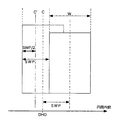
なお、本実施の形態において制御部5は、読み出しの際に磁気ヘッドの中心位置を、図2のC′の位置に制御する必要がある。このため制御部5は、磁気ヘッドの位置をキャリブレートする処理を行う。以下、この処理を図3を参照して説明する。図3は、第1ゾーンにおけるデータトラックの一部を拡大した模式図である。なお、図3では理解を容易にするため、データトラックの重なり合いの状態を模式的に示している。
In this embodiment, the
制御部5は、図3に示すように、読み出すべきデータトラックについて、当該データトラックに対してデータを書き込んだときの磁気ヘッドの中心Cの位置DHOに磁気ヘッドの中心を移動したのでは、上書きされた隣接するデータトラックのデータがノイズとなってしまう。そこで読み出し時には、DHOから書き込み幅Wの半分W/2だけ円周外側へ移動し、さらにトラックピッチSWPの半分、SWP/2だけ円周内側へ移動した位置(DHO−W/2+SWP/2)へ磁気ヘッドを移動する。
As shown in FIG. 3, the
ここで書き込み幅Wが不明の場合は、書き込み時の磁気ヘッドの中心位置DHOからのオフセット(理想的には、−W/2+SWP/2となるべき値)を、実際に読み出しを行ったときのエラーレートから求める。すなわち、制御部5は、例えば読み出し時の磁気ヘッドの位置を中心位置DHOからトラックピッチSWPだけ移動した位置から、所定のステップずつ中心位置DHOへ磁気ヘッドを移動しながら、各ステップにおいてデータの読み出しを試行する。この試行の結果、データのエラーレートは、理想的なポジションにおいて最低となる。そこで、当該エラーレートが最低となるポジションをオフセットとして記憶しておく。
Here, when the write width W is unknown, an offset (ideally a value that should be −W / 2 + SWP / 2) from the center position DHO of the magnetic head at the time of writing is actually obtained. Calculate from error rate. That is, for example, the
そして制御部5は、指定されたデータトラックから読み出しを行う場合、当該指定されたデータトラックへの書き込み時の磁気ヘッドの中心Cの位置DHOに対して、記憶しているオフセットだけ補正した位置へ磁気ヘッドを移動する。そして当該データトラックからのデータの読み出しを行い、RW部4から入力されるデータをホスト側へ出力する。
When the
なお、ここでは書き込みの際の磁気ヘッドの位置(記録素子の位置)を基準としてDHOを定めたが、読み出し時の磁気ヘッドの位置(再生素子の位置)がサーボ情報などから確定できる場合は、この再生素子の位置を基準としてDHOを定めてもよい。この場合、書き込みの際の磁気ヘッドの位置を、再生素子の位置を基準としたDHOからDHO+W/2−SWP/2へとオフセットする。 Here, DHO is determined based on the position of the magnetic head at the time of writing (position of the recording element). However, when the position of the magnetic head at the time of reading (position of the reproducing element) can be determined from servo information or the like, The DHO may be determined based on the position of the reproducing element. In this case, the position of the magnetic head at the time of writing is offset from DHO based on the position of the reproducing element to DHO + W / 2−SWP / 2.
また、LBA(論理ブロックアドレス)を、記録媒体の複数面に亘って割り当てる場合、図4に示すように、読み出し/書き込みを行う面の切り替えを行う位置と、第1、第2ゾーンの切り替えを行う位置(P)とを一致させておく。さらに、第1ゾーンが形成されている部分に対応する裏面側の部分には、第2ゾーンが形成されているようにし、第2ゾーンが形成されている部分に対応する裏面側の部分には、第1ゾーンが形成されているようにする。図4は、記録媒体を、その中心を通るAーA′線で切ったときの断面から見たときのデータトラックの形成状態を表す模式図である。 Further, when assigning LBA (logical block address) over a plurality of surfaces of a recording medium, as shown in FIG. 4, the position for switching the surface to be read / written and the switching between the first and second zones are switched. The position (P) to be performed is matched. Further, the second zone is formed on the back side portion corresponding to the portion where the first zone is formed, and the back side portion corresponding to the portion where the second zone is formed on the back side portion. The first zone is formed. FIG. 4 is a schematic diagram showing the formation state of the data track when the recording medium is viewed from a cross section when cut along the line AA ′ passing through the center thereof.
図4のA−A′断面の図において、幅広の矩形領域は、第1または第2ゾーンのうちで最後に上書きされるデータトラックであり、幅の狭い矩形領域は、他のデータトラックによって一部が上書きされるデータトラックを表している。また、矩形領域内の数字は、書き込み順序の例を示す。 In the cross-sectional view taken along the line AA ′ of FIG. 4, the wide rectangular area is the data track that is overwritten last in the first or second zone, and the narrow rectangular area is shared by the other data tracks. The data track is overwritten. The numbers in the rectangular area indicate examples of the writing order.
すなわち、このように形成しておくことで、データを順次記録していくとき、例えば図4に示すように、データトラック「1」、「2」、「3」と円周外側から順に書き込んだ後、面を切り替えて、「4」、「5」、「6」と、磁気ヘッドを異なる方向(円周外側方向)へ移動させながらデータを記録していき、次に「7」のデータトラックをシークして、「7」、「8」、「9」と、磁気ヘッドを円周内側方向へ移動させながらデータを記録する。そしてゾーンの切り替え位置Pで再び面を切り替えて、逆方向(円周外側方向)へ磁気ヘッドを移動させながらデータを記録する(「10」、「11」、「12」)。この例のように、面の切り替え時にシークを行う必要がなくなり、記録効率を向上できる。 That is, by forming the data in this way, when data is sequentially recorded, for example, as shown in FIG. 4, data tracks “1”, “2”, “3” are written in order from the outer circumference. Then, the surface is switched, and data is recorded while moving the magnetic head in different directions (circumferential outer direction) “4”, “5”, “6”, and then the data track “7” The data is recorded while the magnetic head is moved inward in the circumferential direction, such as “7”, “8”, and “9”. Then, the surface is switched again at the zone switching position P, and data is recorded while moving the magnetic head in the opposite direction (circumferential outer direction) (“10”, “11”, “12”). As in this example, it is not necessary to perform a seek operation when switching surfaces, and the recording efficiency can be improved.
また、図4に示すように、例えば円周外側と、円周内側とで、それぞれのゾーンに含まれるデータトラックの数を変えてもよい。図4では、円周外側において1つのゾーンに2つのデータトラックが含まれ、円周内側において1つのゾーンに3つのデータトラックが含まれるようにした場合を例示している。 Further, as shown in FIG. 4, for example, the number of data tracks included in each zone may be changed between the outer circumference and the inner circumference. FIG. 4 illustrates a case where two data tracks are included in one zone on the outer side of the circumference and three data tracks are included in one zone on the inner side of the circumference.
このようにしておくと、例えばゾーンに含まれるデータトラックの数が少ない領域(R)をランダムアクセスデータの記録領域とし、ゾーンに含まれるデータトラックの数が多い領域(S)をシーケンシャルアクセスデータの記録領域として切り替えることができる。一般に、ゾーンあたりのデータトラック数が少なければ、記憶容量の増大率は減少するが、書き替えの効率が高くなり、ランダムアクセスにより適合できる。なお、ゾーンごとのデータトラックの数を異ならせる領域の境界は、記録媒体の半径位置によって特定できることとしておくのも好適である。利用者は、例えばフォーマット時に当該半径位置を選択して、フォーマットを行わせる。 In this way, for example, an area (R) with a small number of data tracks included in a zone is used as a random access data recording area, and an area (S) with a large number of data tracks included in a zone is used as a sequential access data. It can be switched as a recording area. In general, if the number of data tracks per zone is small, the increase rate of the storage capacity decreases, but the rewriting efficiency becomes high and can be adapted by random access. It should be noted that it is also preferable that the boundary of the area where the number of data tracks for each zone differs can be specified by the radial position of the recording medium. The user selects the radius position at the time of formatting, for example, and causes the formatting to be performed.
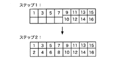
さらに本実施の形態の制御部5は、データを記録するセクタを、図5に示すように、ゾーンごとに、最初に書き込まれるデータトラックから順に、記録媒体1の動径方向に沿って最後に書き込まれるデータトラックへ「1」ずつセクタ番号が増大するように、セクタを配列する。
Further, the
すなわち制御部5は、記録するべきデータとして複数セクタ分のデータの入力を、ホストから受けると、当該データの記録先となるゾーンに含まれるデータトラックの数Nに対応して、記録するべきデータを、N個の書き込みデータ群に分割する。この際、iセクタ目のデータは、このiをNで除した余りRを用い、R+1番目の書き込みデータ群に含めて並べ替えを行う。
That is, when the
例えば書き替えるデータが8セクタ分のデータであるとき、記録先のゾーンに含まれるデータトラックの数が「2」であれば、1,3,5,7番目のセクタに記録するデータからなる第1番目の書き込みデータ群と、2,4,6,8番目のセクタに記録するデータからなる第2番目の書き込みデータ群とを生成する。 For example, when the data to be rewritten is data for 8 sectors, if the number of data tracks included in the recording destination zone is “2”, the first data consisting of data recorded in the first, third, fifth, and seventh sectors. A first write data group and a second write data group composed of data recorded in the second, fourth, sixth and eighth sectors are generated.
そして制御部5は、第1番目の書き込みデータ群に基づいて、ゾーン内で最初に記録されるデータトラック(第1番目のデータトラック)に、4セクタ分(1,3,5,7番目のセクタ)のデータを記録する(図6のステップ1)。次に、制御部5は、第2番目の書き込みデータ群に基づいて、当該4セクタの一部に上書きして隣接する第2番目のデータトラックに4セクタ分(2,4,6,8番目のセクタ)のデータを記録する(図6のステップ2)。このようなセクタの配列と、データの処理により、後から記録するデータトラックのデータをバッファに保持しておく必要がなくなる。つまり、後から記録するデータトラックに既に記録されていたデータを読み出す必要もないので、読み出し・書き込みのためのディスクの周回数分(最大で(N−1)回分)のオーバーヘッドが削減でき、効率的な記録が行われる。
Based on the first write data group, the
なお、このようなセクタ配列及びデータの書き込み方法は、第1ゾーン,第2ゾーンの区別のない、従来のシングル・ライト方式にも適用できる。すなわち、複数のセクタに対する書き込み指示を受けて、セクタごとに書き込むべきデータを、シングル・ライトされるデータトラックのセットの数Nに対応するN個ずつの書き込みデータ群に並べ替えて、N個のデータトラックに対して書き込みを行うこととすればよい。尤も、同じ記録密度に対する書き替え効率は、第1、第2ゾーンのように書き込み方向を切り替える場合に比べ低下する。すなわち、図5,6に示した例と局所的に同程度の記録密度を実現するには、シングル・ライトするデータトラックを4つずつ組とする必要がある。そしてこの場合は、上述の例のように8セクタ分のデータを記録する際に、4つの書き込みデータ群に分割することとなり、書き込み時にディスク4周分の時間がかかる。 Such a sector arrangement and data writing method can also be applied to a conventional single write method without distinction between the first zone and the second zone. That is, in response to a write instruction for a plurality of sectors, the data to be written for each sector is rearranged into N write data groups corresponding to the number N of sets of data tracks to be single-written, and N data The data track may be written. However, the rewriting efficiency for the same recording density is lower than when the writing direction is switched as in the first and second zones. That is, in order to achieve a recording density that is locally the same as the example shown in FIGS. 5 and 6, it is necessary to make a group of four data tracks for single writing. In this case, when data for 8 sectors is recorded as in the above example, it is divided into four write data groups, and it takes time for four rounds of the disk at the time of writing.
このように本実施の形態によると、読み書きの処理負荷を軽減しつつ記憶容量の増大率を向上できる。さらに、特許文献1に開示の技術のように、組になったデータトラックの一方が偏って多く書き替えられた場合に、他方のデータトラックに記録信号が干渉して攻め込んでしまうことを防止できる。
Thus, according to the present embodiment, it is possible to improve the increase rate of the storage capacity while reducing the processing load of reading and writing. Furthermore, as in the technique disclosed in
なお、本発明は、ここで示した実施の形態に限定されるものではなく、その趣旨に基づくあらゆる変形を含む。 In addition, this invention is not limited to embodiment shown here, All the deformation | transformation based on the meaning is included.
1 記録媒体、2 ヘッドアセンブリ、3 ヘッド制御部、4 読み書き部、5 制御部。
DESCRIPTION OF
Claims (7)
複数のセクタに対する書き込み指示を受けて、セクタごとに書き込むべきデータを、所定N個ずつの書き込みデータ群に並べ替えて、N個のデータトラックに対して書き込みを行う制御部と、
を有することを特徴とするディスク装置。 Concentric or spiral data tracks having data tracks partially overwritten by adjacent inner or outer circumferential data tracks, each of the data tracks further including a circumferential direction A recording medium on which a plurality of sectors are formed;
A control unit which receives a write instruction for a plurality of sectors, rearranges data to be written for each sector into a predetermined N number of write data groups, and writes to N data tracks;
A disk device comprising:
前記記録媒体には、
円周内側のデータトラックの一部が、隣接する円周外側のデータトラックによって上書きされる第1ゾーンと、
円周外側のデータトラックの一部が、隣接する円周内側のデータトラックによって上書きされる第2ゾーンと、
が形成されていることを特徴とするディスク装置。 The disk device according to claim 1,
The recording medium includes
A first zone in which a portion of a data track inside the circumference is overwritten by an adjacent data track outside the circumference;
A second zone in which a portion of the outer circumferential data track is overwritten by an adjacent inner circumferential data track;
A disk device characterized in that is formed.
前記制御部は、前記第1ゾーン又は第2ゾーンのいずれか一方のi番目のセクタに書き込むべきデータについて、当該iを前記Nで除した剰余rに相当するr番目のデータトラックに書き込むべきデータとして設定し、前記並べ替えを行うことを特徴とするディスク装置。 The disk device according to claim 2,
For the data to be written in the i-th sector of either the first zone or the second zone, the control unit writes the data to be written in the r-th data track corresponding to the remainder r obtained by dividing i by the N. And performing the sorting.
前記記録媒体の第1ゾーンと第2ゾーンとは、交互に隣接されて配置されていることを特徴とするディスク装置。 The disk device according to claim 2,
The disk device according to claim 1, wherein the first zone and the second zone of the recording medium are alternately arranged adjacent to each other.
前記記録媒体の第1ゾーンと第2ゾーンとには、それぞれ前記N個(Nは2以上)のデータトラックが含まれることを特徴とするディスク装置。 The disk device according to claim 2,
The disk device according to claim 1, wherein the first zone and the second zone of the recording medium each include the N data tracks (N is 2 or more).
前記記録媒体上で第1ゾーンと第2ゾーンとに含まれるデータトラックの数Nが、互いに異なる複数の領域が形成されていることを特徴とするディスク装置。 The disk device according to claim 5,
A disk device, wherein a plurality of areas having different numbers N of data tracks included in the first zone and the second zone are formed on the recording medium.
前記複数の領域の境界は利用者がフォーマット時に指定することを特徴とするディスク装置。
The disk device according to claim 6, wherein
A disk device characterized in that a boundary of the plurality of areas is specified by a user at the time of formatting.
Priority Applications (3)
| Application Number | Priority Date | Filing Date | Title |
|---|---|---|---|
| JP2005115681A JP2006294162A (en) | 2005-04-13 | 2005-04-13 | Disk device |
| CNB2006100735215A CN100449614C (en) | 2005-04-13 | 2006-04-12 | Disk drive |
| US11/404,156 US7486460B2 (en) | 2005-04-13 | 2006-04-13 | Disk drive with enhanced storage capacity increase ratio |
Applications Claiming Priority (1)
| Application Number | Priority Date | Filing Date | Title |
|---|---|---|---|
| JP2005115681A JP2006294162A (en) | 2005-04-13 | 2005-04-13 | Disk device |
Publications (1)
| Publication Number | Publication Date |
|---|---|
| JP2006294162A true JP2006294162A (en) | 2006-10-26 |
Family
ID=37077782
Family Applications (1)
| Application Number | Title | Priority Date | Filing Date |
|---|---|---|---|
| JP2005115681A Pending JP2006294162A (en) | 2005-04-13 | 2005-04-13 | Disk device |
Country Status (3)
| Country | Link |
|---|---|
| US (1) | US7486460B2 (en) |
| JP (1) | JP2006294162A (en) |
| CN (1) | CN100449614C (en) |
Cited By (4)
| Publication number | Priority date | Publication date | Assignee | Title |
|---|---|---|---|---|
| WO2011052474A1 (en) * | 2009-10-29 | 2011-05-05 | 昭和電工株式会社 | Method for examining a magnetic recording medium |
| JP2013140661A (en) * | 2011-12-28 | 2013-07-18 | Hgst Netherlands B V | System, method and apparatus for shingled magnetic recording in disc drive device |
| US8559123B2 (en) | 2010-06-14 | 2013-10-15 | Tdk Corporation | Magnetic recording device, magnetic recording method and magnetic recording medium for shingle write scheme |
| US8665548B2 (en) | 2011-03-14 | 2014-03-04 | Tdk Corporation | Magnetic recording device and magnetic recording method |
Families Citing this family (58)
| Publication number | Priority date | Publication date | Assignee | Title |
|---|---|---|---|---|
| US7567397B2 (en) * | 2006-09-11 | 2009-07-28 | Hitachi Global Storage Technologies Netherlands B.V. | Adjacent Track Interference (ATI) identification methodology |
| US7830632B2 (en) * | 2007-06-19 | 2010-11-09 | Samsung Electronics Co., Ltd. | Large data block written on overlapping tracks in a hard disk drive |
| JP4895308B2 (en) * | 2008-01-30 | 2012-03-14 | 東芝ストレージデバイス株式会社 | Recording method for magnetic disk device and magnetic disk device |
| JP2010040114A (en) * | 2008-08-06 | 2010-02-18 | Hitachi Global Storage Technologies Netherlands Bv | Magnetic disk drive |
| US8023214B2 (en) * | 2009-09-10 | 2011-09-20 | Tdk Corporation | Rework method and apparatus of magnetic record medium, information |
| US8385157B1 (en) | 2009-09-30 | 2013-02-26 | Western Digital Technologies, Inc. | Method and system for performing EAMR recording at high density using a large thermal spot size |
| US8443167B1 (en) | 2009-12-16 | 2013-05-14 | Western Digital Technologies, Inc. | Data storage device employing a run-length mapping table and a single address mapping table |
| US8194340B1 (en) | 2010-03-18 | 2012-06-05 | Western Digital Technologies, Inc. | Disk drive framing write data with in-line mapping data during write operations |
| US9330715B1 (en) | 2010-03-22 | 2016-05-03 | Western Digital Technologies, Inc. | Mapping of shingled magnetic recording media |
| US8699185B1 (en) | 2012-12-10 | 2014-04-15 | Western Digital Technologies, Inc. | Disk drive defining guard bands to support zone sequentiality when butterfly writing shingled data tracks |
| US8856438B1 (en) | 2011-12-09 | 2014-10-07 | Western Digital Technologies, Inc. | Disk drive with reduced-size translation table |
| US8693133B1 (en) | 2010-03-22 | 2014-04-08 | Western Digital Technologies, Inc. | Systems and methods for improving sequential data rate performance using sorted data zones for butterfly format |
| US8687306B1 (en) | 2010-03-22 | 2014-04-01 | Western Digital Technologies, Inc. | Systems and methods for improving sequential data rate performance using sorted data zones |
| US9563397B1 (en) | 2010-05-05 | 2017-02-07 | Western Digital Technologies, Inc. | Disk drive using non-volatile cache when garbage collecting log structured writes |
| US8179627B2 (en) * | 2010-06-10 | 2012-05-15 | Seagate Technology International | Floating guard band for shingle magnetic recording |
| US9530436B1 (en) * | 2010-08-12 | 2016-12-27 | Western Digital Technologies, Inc. | Methods and systems for providing data security in data storage devices |
| US8954664B1 (en) | 2010-10-01 | 2015-02-10 | Western Digital Technologies, Inc. | Writing metadata files on a disk |
| US8756361B1 (en) | 2010-10-01 | 2014-06-17 | Western Digital Technologies, Inc. | Disk drive modifying metadata cached in a circular buffer when a write operation is aborted |
| US8854751B2 (en) * | 2011-01-06 | 2014-10-07 | Seagate Technology Llc | Reducing errors resulting from width variability of storage media write tracks |
| JP2012174325A (en) * | 2011-02-23 | 2012-09-10 | Toshiba Corp | Information recorder and information recording method |
| JP2012212488A (en) * | 2011-03-30 | 2012-11-01 | Toshiba Corp | Information recording device and information recording method |
| JP2012230736A (en) * | 2011-04-26 | 2012-11-22 | Sharp Corp | Magnetic recording and reproducing device and magnetic recording medium |
| US8913335B2 (en) * | 2011-05-23 | 2014-12-16 | HGST Netherlands B.V. | Storage device with shingled data and unshingled cache regions |
| US8793429B1 (en) | 2011-06-03 | 2014-07-29 | Western Digital Technologies, Inc. | Solid-state drive with reduced power up time |
| US8693134B1 (en) | 2011-06-23 | 2014-04-08 | Western Digital Technologies, Inc. | Alternating wedge repeatable runout (WRRO) pattern |
| US9003101B1 (en) | 2011-06-29 | 2015-04-07 | Western Digital Technologies, Inc. | Prioritized access for media with heterogeneous access rates |
| US8756382B1 (en) | 2011-06-30 | 2014-06-17 | Western Digital Technologies, Inc. | Method for file based shingled data storage utilizing multiple media types |
| JP5548993B2 (en) * | 2011-09-07 | 2014-07-16 | シャープ株式会社 | Magnetic recording / reproducing apparatus and magnetic recording medium |
| JP5581285B2 (en) | 2011-09-07 | 2014-08-27 | シャープ株式会社 | Magnetic recording / reproducing apparatus and magnetic recording medium |
| US9213493B1 (en) | 2011-12-16 | 2015-12-15 | Western Digital Technologies, Inc. | Sorted serpentine mapping for storage drives |
| US8819367B1 (en) | 2011-12-19 | 2014-08-26 | Western Digital Technologies, Inc. | Accelerated translation power recovery |
| US8612706B1 (en) | 2011-12-21 | 2013-12-17 | Western Digital Technologies, Inc. | Metadata recovery in a disk drive |
| US9189395B2 (en) * | 2012-04-27 | 2015-11-17 | Seagate Technology Llc | Method and apparatus for adjustable virtual addressing for data storage |
| US8874875B2 (en) * | 2012-06-29 | 2014-10-28 | HGST Netherlands B.V. | ICC-NCQ command scheduling for shingle-written magnetic recording (SMR) Drives |
| US8976478B1 (en) * | 2012-10-10 | 2015-03-10 | Seagate Technology Llc | Band rewrites based on error scan counts |
| US9336814B1 (en) | 2013-03-12 | 2016-05-10 | Western Digital (Fremont), Llc | Inverse tapered waveguide for use in a heat assisted magnetic recording head |
| US8867161B2 (en) | 2013-03-15 | 2014-10-21 | Seagate Technology Llc | Shingled magnetic recording with variable track spacing |
| US9064528B1 (en) | 2013-05-17 | 2015-06-23 | Western Digital Technologies, Inc. | Interferometric waveguide usable in shingled heat assisted magnetic recording in the absence of a near-field transducer |
| US8947985B1 (en) | 2013-07-16 | 2015-02-03 | Western Digital (Fremont), Llc | Heat assisted magnetic recording transducers having a recessed pole |
| US8923102B1 (en) | 2013-07-16 | 2014-12-30 | Western Digital (Fremont), Llc | Optical grating coupling for interferometric waveguides in heat assisted magnetic recording heads |
| US9460751B2 (en) * | 2013-09-16 | 2016-10-04 | Seagate Technology Llc | Binding shingled recording bands |
| US9489145B2 (en) | 2013-12-09 | 2016-11-08 | HGST Netherlands B.V. | Disk drive including I-regions having configurable final logical block addresses |
| US8941943B1 (en) | 2013-12-09 | 2015-01-27 | HGST Netherlands B.V. | Dynamic variable capacity hard disk drive |
| US8867153B1 (en) | 2013-12-09 | 2014-10-21 | HGST Netherlands B.V. | Method and apparatus for dynamic track squeeze in a hard drive |
| US8922925B1 (en) * | 2013-12-09 | 2014-12-30 | HGST Netherlands B.V. | Actively written guard bands in a cold storage or mixed mode drive |
| US9501393B2 (en) | 2014-01-27 | 2016-11-22 | Western Digital Technologies, Inc. | Data storage system garbage collection based on at least one attribute |
| US9142233B1 (en) | 2014-02-28 | 2015-09-22 | Western Digital (Fremont), Llc | Heat assisted magnetic recording writer having a recessed pole |
| US9208810B1 (en) * | 2014-04-24 | 2015-12-08 | Western Digital Technologies, Inc. | Data storage device attenuating interference from first spiral track when reading second spiral track |
| US9129658B1 (en) * | 2014-05-07 | 2015-09-08 | Kabushiki Kaisha Toshiba | Magnetic disk drive and method for controlling data rewrite |
| US9129627B1 (en) * | 2014-05-15 | 2015-09-08 | Seagate Technology Llc | Sector-based write operation |
| US8953269B1 (en) | 2014-07-18 | 2015-02-10 | Western Digital Technologies, Inc. | Management of data objects in a data object zone |
| US9875055B1 (en) | 2014-08-04 | 2018-01-23 | Western Digital Technologies, Inc. | Check-pointing of metadata |
| US9542965B2 (en) * | 2015-04-02 | 2017-01-10 | Seagate Technology Llc | Skewed shingled magnetic recording data reader |
| US9368131B1 (en) * | 2015-04-03 | 2016-06-14 | Western Digital (Fremont), Llc | Data storage device employing mirrored cross-track profiles for top and bottom disk surfaces |
| US9817579B2 (en) | 2015-09-18 | 2017-11-14 | Seagate Technology Llc | Maximize SMR drive capacity |
| JP6699905B2 (en) * | 2017-08-31 | 2020-05-27 | 株式会社東芝 | Magnetic disk device and recording area setting method |
| JP2020140752A (en) | 2019-02-28 | 2020-09-03 | 株式会社東芝 | Magnetic disk drive and light processing method |
| JP7404285B2 (en) * | 2021-02-16 | 2023-12-25 | 株式会社東芝 | Magnetic disk device and write processing method |
Family Cites Families (8)
| Publication number | Priority date | Publication date | Assignee | Title |
|---|---|---|---|---|
| US6185063B1 (en) * | 1997-02-13 | 2001-02-06 | Seagate Technology Llc | Methods and apparatus for overlapping data tracks on a storage medium |
| JP3303859B2 (en) * | 1999-10-22 | 2002-07-22 | 日本電気株式会社 | Magnetic recording medium and magnetic recording / reproducing apparatus using the same |
| WO2002027723A1 (en) * | 2000-09-27 | 2002-04-04 | Seagate Technology Llc | Method to achieve higher track density by allowing only one-sided track encroachment |
| US6891694B2 (en) * | 2002-08-23 | 2005-05-10 | Hitachi Global Storage Technologies Netherlands B.V. | Method for writing streaming audiovisual data to a disk drive |
| US7996645B2 (en) * | 2003-09-26 | 2011-08-09 | Hitachi Global Storage Technologies Netherlands B.V. | Log-structured file system for disk drives with shingled writing |
| US6967810B2 (en) * | 2003-09-29 | 2005-11-22 | Hitachi Global Storage Technologies Netherlands B.V. | System and method for writing HDD depending on direction of head skew |
| US7490212B2 (en) * | 2003-09-29 | 2009-02-10 | Hitachi Global Storage Technologies Netherlands B.V. | System and method for writing data to dedicated bands of a hard disk drive |
| US7133241B2 (en) * | 2005-04-11 | 2006-11-07 | Hitachi Global Storage Technologies Netherlands B.V. | Method and apparatus for optimizing record quality with varying track and linear density by allowing overlapping data tracks |
-
2005
- 2005-04-13 JP JP2005115681A patent/JP2006294162A/en active Pending
-
2006
- 2006-04-12 CN CNB2006100735215A patent/CN100449614C/en not_active Expired - Fee Related
- 2006-04-13 US US11/404,156 patent/US7486460B2/en not_active Expired - Fee Related
Cited By (5)
| Publication number | Priority date | Publication date | Assignee | Title |
|---|---|---|---|---|
| WO2011052474A1 (en) * | 2009-10-29 | 2011-05-05 | 昭和電工株式会社 | Method for examining a magnetic recording medium |
| JP2011096313A (en) * | 2009-10-29 | 2011-05-12 | Showa Denko Kk | Method of inspecting magnetic recording medium |
| US8559123B2 (en) | 2010-06-14 | 2013-10-15 | Tdk Corporation | Magnetic recording device, magnetic recording method and magnetic recording medium for shingle write scheme |
| US8665548B2 (en) | 2011-03-14 | 2014-03-04 | Tdk Corporation | Magnetic recording device and magnetic recording method |
| JP2013140661A (en) * | 2011-12-28 | 2013-07-18 | Hgst Netherlands B V | System, method and apparatus for shingled magnetic recording in disc drive device |
Also Published As
| Publication number | Publication date |
|---|---|
| CN1848247A (en) | 2006-10-18 |
| CN100449614C (en) | 2009-01-07 |
| US7486460B2 (en) | 2009-02-03 |
| US20060232874A1 (en) | 2006-10-19 |
Similar Documents
| Publication | Publication Date | Title |
|---|---|---|
| JP2006294162A (en) | Disk device | |
| JP5485770B2 (en) | Magnetic disk unit | |
| JP4719047B2 (en) | Information recording device | |
| JP2007048335A (en) | Disk drive | |
| JP2006294163A (en) | Disk drive | |
| JP2008243269A (en) | Disk driving device and data rewriting method thereof | |
| JP3373690B2 (en) | Disk-shaped recording medium and disk device | |
| JP2007073138A (en) | Disk device | |
| JPH01137410A (en) | Method and apparatus of disc memory | |
| JP2006139902A (en) | Recording density varying method of data recording medium, disk drive using the same, setting method of recording density, and data recording method | |
| KR20020091185A (en) | Magnetic storage medium, method of controlling track pitch of the medium, and magnetic recorder for the medium | |
| KR101012476B1 (en) | Data recording/reproduction device and data recording/reproduction method | |
| JPH09265746A (en) | Disk device and head changeover method thereon | |
| US7019939B2 (en) | Apparatus and method for positioning head at target position on disk | |
| JP2007293968A (en) | Write-once storage device, control method, and program | |
| US6483654B2 (en) | Disk drive recording apparatus having actuator arm with dual heads and head switching control method | |
| JP2009026443A (en) | Hard disk drive including numbers of data sectors and hard disk drive controller for controlling the same | |
| JP4489125B2 (en) | Hard disk device and head positioning method | |
| TW200304617A (en) | Method of generating an efficient sequence of multi-level random numbers used for an information recording medium | |
| US20100149681A1 (en) | Recording method and storage device | |
| JP2008276875A (en) | Data writing method using magnetic disk device, off-track margin setting method, magnetic disk device, and off-track margin setting device | |
| JP2003016745A (en) | Disk storage and method for positioning head in the device | |
| US20050078949A1 (en) | Reproducing apparatus and method, and recording apparatus and method | |
| JP2006031825A (en) | Recording and reproducing control method, and recording and reproducing control apparatus | |
| US8098448B2 (en) | Method for setting zone format of a disk for storing data and disk drive |