JP2006293200A - Lens barrel of camera - Google Patents
Lens barrel of camera Download PDFInfo
- Publication number
- JP2006293200A JP2006293200A JP2005116755A JP2005116755A JP2006293200A JP 2006293200 A JP2006293200 A JP 2006293200A JP 2005116755 A JP2005116755 A JP 2005116755A JP 2005116755 A JP2005116755 A JP 2005116755A JP 2006293200 A JP2006293200 A JP 2006293200A
- Authority
- JP
- Japan
- Prior art keywords
- shutter
- lens group
- lens
- lens barrel
- optical system
- Prior art date
- Legal status (The legal status is an assumption and is not a legal conclusion. Google has not performed a legal analysis and makes no representation as to the accuracy of the status listed.)
- Pending
Links
Images


Classifications
-
- G—PHYSICS
- G02—OPTICS
- G02B—OPTICAL ELEMENTS, SYSTEMS OR APPARATUS
- G02B7/00—Mountings, adjusting means, or light-tight connections, for optical elements
- G02B7/02—Mountings, adjusting means, or light-tight connections, for optical elements for lenses
- G02B7/04—Mountings, adjusting means, or light-tight connections, for optical elements for lenses with mechanism for focusing or varying magnification
- G02B7/08—Mountings, adjusting means, or light-tight connections, for optical elements for lenses with mechanism for focusing or varying magnification adapted to co-operate with a remote control mechanism
-
- G—PHYSICS
- G02—OPTICS
- G02B—OPTICAL ELEMENTS, SYSTEMS OR APPARATUS
- G02B7/00—Mountings, adjusting means, or light-tight connections, for optical elements
- G02B7/02—Mountings, adjusting means, or light-tight connections, for optical elements for lenses
- G02B7/04—Mountings, adjusting means, or light-tight connections, for optical elements for lenses with mechanism for focusing or varying magnification
- G02B7/10—Mountings, adjusting means, or light-tight connections, for optical elements for lenses with mechanism for focusing or varying magnification by relative axial movement of several lenses, e.g. of varifocal objective lens
-
- G—PHYSICS
- G03—PHOTOGRAPHY; CINEMATOGRAPHY; ANALOGOUS TECHNIQUES USING WAVES OTHER THAN OPTICAL WAVES; ELECTROGRAPHY; HOLOGRAPHY
- G03B—APPARATUS OR ARRANGEMENTS FOR TAKING PHOTOGRAPHS OR FOR PROJECTING OR VIEWING THEM; APPARATUS OR ARRANGEMENTS EMPLOYING ANALOGOUS TECHNIQUES USING WAVES OTHER THAN OPTICAL WAVES; ACCESSORIES THEREFOR
- G03B17/00—Details of cameras or camera bodies; Accessories therefor
- G03B17/02—Bodies
- G03B17/17—Bodies with reflectors arranged in beam forming the photographic image, e.g. for reducing dimensions of camera
-
- G—PHYSICS
- G03—PHOTOGRAPHY; CINEMATOGRAPHY; ANALOGOUS TECHNIQUES USING WAVES OTHER THAN OPTICAL WAVES; ELECTROGRAPHY; HOLOGRAPHY
- G03B—APPARATUS OR ARRANGEMENTS FOR TAKING PHOTOGRAPHS OR FOR PROJECTING OR VIEWING THEM; APPARATUS OR ARRANGEMENTS EMPLOYING ANALOGOUS TECHNIQUES USING WAVES OTHER THAN OPTICAL WAVES; ACCESSORIES THEREFOR
- G03B9/00—Exposure-making shutters; Diaphragms
- G03B9/08—Shutters
- G03B9/10—Blade or disc rotating or pivoting about axis normal to its plane
- G03B9/14—Two separate members moving in opposite directions
-
- H—ELECTRICITY
- H04—ELECTRIC COMMUNICATION TECHNIQUE
- H04N—PICTORIAL COMMUNICATION, e.g. TELEVISION
- H04N2101/00—Still video cameras
Landscapes
- Physics & Mathematics (AREA)
- General Physics & Mathematics (AREA)
- Optics & Photonics (AREA)
- Studio Devices (AREA)
- Lens Barrels (AREA)
- Shutters For Cameras (AREA)
Abstract
Description
本発明は、焦点距離を変更することができる撮影光学系を有し、焦点距離の変更に伴い撮影光学系の主点位置が移動するカメラのレンズ鏡筒に関するものである。 The present invention relates to a lens barrel of a camera having a photographing optical system capable of changing a focal length, and a principal point position of the photographing optical system is moved in accordance with the change of the focal length.
カメラのレンズ鏡筒、特に小型化を要求されるいわゆるコンパクトタイプのカメラのレンズ鏡筒には、シャッタを内蔵しているものが多い(例えば、特許文献1)。
特許文献1に記載のレンズ鏡筒では、シャッタユニットが可動レンズ群と一体的に設けられており、可動レンズ群の移動とともにシャッタユニットが移動するように構成されている。
また、シャッタユニットを固定として、このシャッタユニットの前方及び後方に可動レンズ群を配置したレンズ鏡筒もある。
Many camera lens barrels, particularly so-called compact type camera lens barrels that are required to be miniaturized, incorporate a shutter (for example, Patent Document 1).
In the lens barrel described in
There is also a lens barrel in which the shutter unit is fixed and movable lens groups are arranged in front and rear of the shutter unit.
しかし、前者(特許文献1)の場合、可動レンズ群に加えてシャッタユニットも移動させる必要がある。レンズ群に対してシャッタユニットは大きく、かつ、重量も重いので、シャッタユニットを含めた可動レンズ群を駆動するモータ等のアクチュエータに要求される駆動力も大きくなる。また、大きなシャッタユニットが移動する軌跡となる部分は移動スペースを確保する必要もある。その結果、レンズ鏡筒全体が大型化してしまうという問題があった。
一方、後者の場合、可動レンズ群がシャッタユニットの前方及び後方に分かれて配置されているので、レンズ鏡筒の全長が長くなってしまうという問題があった。
On the other hand, in the latter case, there is a problem that the entire length of the lens barrel becomes long because the movable lens group is arranged separately at the front and rear of the shutter unit.
本発明の課題は、焦点距離の変更に伴い撮影光学系の主点位置が移動するカメラのレンズ鏡筒を小型化かつ軽量化して提供することである。 SUMMARY OF THE INVENTION An object of the present invention is to provide a lens barrel of a camera in which the principal point position of a photographing optical system moves with a change in focal length in a reduced size and weight.
前記課題を解決するために、請求項1の発明は、焦点距離を変更することができる撮影光学系と、前記撮影光学系を形成するレンズ群であって、焦点距離を変更するときに光軸に沿った方向に移動する少なくとも1つの可動レンズ群と、を備え、前記撮影光学系の主点位置が前記可動レンズ群の光軸に沿った方向の移動に伴い移動するレンズ鏡筒において、前記撮影光学系を通過する撮影光束を遮断することができるシャッタ羽根を有したシャッタユニットを前記可動レンズ群の可動領域外に固定したこと、を特徴とするカメラのレンズ鏡筒である。
請求項2の発明は、請求項1に記載のカメラのレンズ鏡筒において、前記シャッタ羽根が前記撮影光学系の光束を遮断する動作は、長方形の撮像領域の短辺方向に略沿った方向の動作であること、を特徴とするカメラのレンズ鏡筒である。
請求項3の発明は、請求項1又は請求項2に記載のカメラのレンズ鏡筒において、前記シャッタ羽根として、前記撮影光学系の光軸に略直交する異なる方向へ各々駆動される複数枚のシャッタ羽根が設けられていること、を特徴とするカメラのレンズ鏡筒である。
請求項4の発明は、請求項1から請求項3までのいずれか1項に記載のカメラのレンズ鏡筒において、前記シャッタ羽根は、前記可動レンズ群の可動領域の直近に配置されていること、を特徴とするカメラのレンズ鏡筒である。
In order to solve the above-mentioned problem, the invention of
According to a second aspect of the present invention, in the lens barrel of the camera according to the first aspect, the operation of the shutter blade blocking the light flux of the photographing optical system is performed in a direction substantially along the short side direction of the rectangular imaging region. It is a lens barrel of a camera characterized by operation.
According to a third aspect of the present invention, in the lens barrel of the camera according to the first or second aspect, the shutter blade is a plurality of sheets each driven in different directions substantially orthogonal to the optical axis of the photographing optical system. A lens barrel of a camera, characterized in that shutter blades are provided.
According to a fourth aspect of the present invention, in the lens barrel of the camera according to any one of the first to third aspects, the shutter blade is disposed in the immediate vicinity of the movable region of the movable lens group. The lens barrel of the camera characterized by the above.
本発明によれば、以下の効果を奏することができる。
請求項1の発明によれば、撮影光学系を通過する撮影光束を遮断することができるシャッタ羽根を有したシャッタユニットを可動レンズ群の可動領域外に固定したので、シャッタユニットを可動レンズ群とともに移動する必要がなく、シャッタユニットの移動軌跡部分を有効に活用することができ、また、可動レンズ群の駆動に用いるモータも小型とすることができ、レンズ鏡筒を小型かつ軽量にすることができる。
According to the present invention, the following effects can be obtained.
According to the first aspect of the present invention, since the shutter unit having the shutter blade capable of blocking the photographing light beam passing through the photographing optical system is fixed outside the movable region of the movable lens group, the shutter unit is mounted together with the movable lens group. It is not necessary to move, the moving locus part of the shutter unit can be used effectively, the motor used for driving the movable lens group can be made small, and the lens barrel can be made small and light. it can.
請求項2の発明によれば、シャッタ羽根が撮影光学系の光束を遮断する動作は、長方形の撮像領域の短辺方向に略沿った方向の動作であるので、シャッタ羽根の移動時間が短くなり、露光むらを低減することができる。
According to the invention of
請求項3の発明によれば、シャッタ羽根として、撮影光学系の光軸に略直交する異なる方向へ各々駆動される複数枚のシャッタ羽根が設けられているので、シャッタ羽根の移動距離が短くなり、露光むらを低減することができる。また、シャッタ羽根の退避スペースが僅かで済み、レンズ鏡筒を小型にすることができる。
According to the invention of
請求項4の発明によれば、シャッタ羽根は、可動レンズ群の可動領域の直近に配置されているので、露光むらを少なくすることができる。
According to the invention of
焦点距離の変更に伴い撮影光学系の主点位置が移動するカメラのレンズ鏡筒を小型化かつ軽量化するという目的を、シャッタユニットの位置及び形態を改良することにより実現した。 The purpose of reducing the size and weight of the lens barrel of the camera in which the principal point position of the photographic optical system moves with the change of the focal length is realized by improving the position and form of the shutter unit.
以下、図面等を参照して、本発明の実施例をあげて、さらに詳しく説明する。
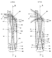
図1は、本発明を適用したレンズ鏡筒の実施例を対物レンズの光軸側から見た外観図である。図2は、図1のII−II部矢視断面図である。図2(a)には、広角端状態を示し、図2(b)には、望遠端状態を示している。図3は、図2のIII―III部矢視断面図である。図4は、図3のIV−IV部矢視断面図である。図5は、図3のV−V部矢視断面図である。
Hereinafter, the present invention will be described in more detail with reference to the drawings and the like.
FIG. 1 is an external view of an embodiment of a lens barrel to which the present invention is applied as viewed from the optical axis side of an objective lens. 2 is a cross-sectional view taken along the line II-II in FIG. FIG. 2A shows the wide-angle end state, and FIG. 2B shows the telephoto end state. 3 is a cross-sectional view taken along the line III-III in FIG. 4 is a cross-sectional view taken along the line IV-IV in FIG. 5 is a cross-sectional view taken along the line VV in FIG.
実施例1のレンズ鏡筒1は、その途中で光軸の方向を変換するいわゆる屈曲光学系を備え、例えばデジタルスチルカメラの撮影用レンズ鏡筒として用いられるものである。
レンズ鏡筒1は、鏡胴部2と、モータホルダ部3と、ガイド軸4と、回転防止軸5とを備えている(ガイド軸4、回転防止軸5は図3参照)。
鏡胴部(鏡筒本体)2は、略直方体のボックス状に形成され、その内部に後述する屈曲光学系を収容するものである。
モータホルダ部3は、鏡胴部2の側部に対して着脱可能に装着され、後述するリードスクリュー110,120及びモータ130,140を支持するものである。モータホルダ部3は、その鏡胴部2との接合部に開口を有するボックス状に形成されている。また、鏡胴部2のモータホルダ部3側の部分にも開口が形成され、鏡胴部2とモータホルダ部3は、これらの開口同士を対向させて接合されることによって、その内部に連続した空間部が形成されるものである。
なお、これらの鏡胴部2及びモータホルダ部3は、それぞれ樹脂系材料をインジェクション成形することによって形成されている。
ガイド軸4は、鏡胴部2の内部に設けられ、光軸I2と平行して延在する丸棒状の部材であって、後述する第2レンズ群40及び第3レンズ群50をその光軸方向にガイドするものである。
回転防止軸5は、ガイド軸4に対して第2レンズ群40及び第3レンズ群50を挟んだ反対側の領域に設けられ、光軸I2と平行して延在する丸棒状の部材であって、第2レンズ群40及び第3レンズ群50がガイド軸4回りに回転することを防止するものである。
The
The
The lens barrel portion (lens barrel main body) 2 is formed in a substantially rectangular parallelepiped box shape, and accommodates a bending optical system described later therein.
The
The
The
The anti-rotation shaft 5 is a round bar-like member that is provided in a region opposite to the
鏡胴部2は、その内部に収容される光学系として、対物レンズ10と、プリズム20と、第1レンズ群30と、第2レンズ群40と、第3レンズ群50と、シャッタユニットSと、第4レンズ群70と、ローパスフィルタ(LPF)80と、CCD90とを備えている。
The
対物レンズ10は、鏡胴部2の被写体側の前面部の通常撮影時における上端部付近に形成された開口部に隣接して固定されている。
プリズム20は、鏡胴部2の対物レンズ10の射出側の領域に固定され、対物レンズ10から出た像光の方向を例えば90度変換する屈曲部である。
The
The
第1レンズ群30は、鏡胴部2のプリズム20の射出側(通常撮影時における下側)の領域に固定されている。なお、この第1レンズ群30以降の光学系の光軸I2は、対物レンズ10の光軸I1に対して直交して配置されている。この光軸I2は、カメラの通常撮影時において略鉛直方向に配置される。
第1レンズ群30は、その光軸I2方向に入光側から順次配列されたレンズ31,32を張り合わせて構成され、レンズ31は、レンズ32よりもその外径を大きく形成されている。第1レンズ群30は、レンズ31の外周縁部がレンズ32から突き出した部分を、鏡胴部2に形成された凹部に固定することによってその位置決めが行われる。
The
The
図6は、対物レンズ10及び第1レンズ群30の構成を示す図である。図6(a)は、第1レンズ群30を光軸I1,I2にそれぞれ直交する方向から見た図であり、図6(b)、図6(c)はそれぞれ図6(a)のb−b部矢視図及びc−c部矢視図である。
対物レンズ10は、その外周縁部のうち第1レンズ群30に隣接した部分を切り落としたDカット形状に形成され、この部分の端面10aは、通常撮影時における下側に面した平坦面になっている。
一方、第1レンズ群30のレンズ31,32は、それぞれその外周縁部のうち対物レンズ10に隣接した部分を切り落としたDカット形状に形成され、この部分の端面31a,32aは、光軸I1の対物側に面した平坦面になっている。そして、第1レンズ群30は、レンズ31の端面31aを、対物レンズ10の裏面側に微小な間隔を隔てて対向させて配置されている。
FIG. 6 is a diagram illustrating configurations of the
The
On the other hand, the
第2レンズ群40は、鏡胴部2の第1レンズ群30の射出側の空間部内に配置され、鏡胴部2に対して光軸I2方向に移動可能に支持された第1の可動レンズ群である。
第2レンズ群40は、その周囲に備えられた枠体であるレンズホルダ41を有し、この可動レンズホルダ41は、ガイド軸4及び回転防止軸5に対してその長手方向に摺動することによって光軸I2方向に移動する。
図3に示すように、ガイド軸4及び回転防止軸5は、レンズホルダ41の光軸I2を挟んだ両側の領域に設けられ、それぞれ光軸I2と平行に延在している。
The
The
As shown in FIG. 3, the
図5に示すように、レンズホルダ41は、開口部41aと、溝部41bとを備えている。
開口部41aは、ガイド軸4が挿入されるものであって、その直径はガイド軸4の直径に対して不可避的に設けられるクリアランスだけ大きく設定されている。
溝部41bは、回転防止軸5が挿入されるものであって、レンズホルダ41の外縁部を凹ませて形成され、その溝幅は回転防止軸5の直径に対して不可避的に設けられるクリアランスだけ大きく設定されている。なお、回転防止軸5は、溝部41bの延在方向においてはレンズホルダ41を拘束せず、万一開口部41aと溝部41bとの間に寸法のばらつきがあった場合にその吸収が可能となっている。
As shown in FIG. 5, the
The opening 41 a is inserted with the
The
また、レンズホルダ41は、レンズホルダナット42を備えている。レンズホルダナット42は、後述するリードスクリュー110がその内部に挿入される溝部の一方の内面に、このリードスクリュー110と係合するめネジ部が形成された第1の被駆動部材であって、この溝部を挟んだ二股状に形成されている。レンズホルダナット42は、レンズホルダ41の外周縁部に光軸I2と平行に配置された軸部41c回りに回転可能に支持されるとともに、バネ42a,52a(図8参照)によってその一方の回転方向側に付勢され、めネジ部が後述するリードスクリューの表面に押圧されるようになっている。
Further, the
第3レンズ群50は、第2レンズ群40の射出側に設けられ、鏡胴部2の第2レンズ群40を収容する空間部内に収容されている。第3レンズ群50は、鏡胴部2に対して光軸I2方向に移動可能に支持された第2の可動レンズ群である。
第3レンズ群50は、その周囲に備えられた枠体であるレンズホルダ51を有し、この可動レンズホルダ51は、上述した可動レンズホルダ41と同様にガイド軸4及び回転防止軸5によって、光軸I2方向に移動可能に支持されている。
また、レンズホルダ51は、上述したレンズホルダ41のレンズホルダナット42と同様に構成され、後述するリードスクリュー120と係合されるレンズホルダナット52を備えている。
なお第2レンズ群40の移動範囲と第3レンズ群50の移動範囲とは、その一部が相互に重なった範囲に設定されている。
The
The
The
The moving range of the
図2に示すように、広角端では、第2レンズ群40及び第3レンズ群50は、第1レンズ群30に近い位置にあり、望遠端では、後述のシャッタユニットSに近い位置に移動する。そして、この第2レンズ群40及び第3レンズ群50の移動に伴い、主点位置も広角端における主点位置HWと望遠端における主点位置HTとの間で移動する。
As shown in FIG. 2, the
シャッタユニットSは、第3レンズ群50から出て第4レンズ群70に入光する像光を遮断するシャッタ羽根170(後述)と、シャッタ羽根170よりもCCD90側に配置され、像光の光量を低減するNDフィルタ62aを備えた絞り部(光量調整部)とを備えている。この絞り部は、図示しない制御部が出力する挿入指示信号、退避信号に応じて所定のNDフィルタ62aを光路上に出し入れするものである。
シャッタユニットSは、これらのシャッタ羽根170、NDフィルタ62aをそれぞれ駆動するシャッタ駆動部160及びNDフィルタ駆動部62をそれぞれ備えている。
シャッタ駆動部160及びNDフィルタ駆動部62は、光路を挟んだ両側にそれぞれ設けられ、光軸I2方向における位置は、シャッタ駆動部160は後述するモータ140の光軸I2方向像側に隣接して配置され、NDフィルタ駆動部62は、シャッタ駆動部160よりも光軸I2方向対物側にオフセットして配置されている。
シャッタ羽根170及びシャッタ駆動部160の詳細については、後述する。
The shutter unit S is disposed on the
The shutter unit S includes a
The
Details of the
第4レンズ群70は、鏡胴部2のシャッタユニットSの射出側の領域に固定されており、像光がCCD90へ入射する入射角度を光軸I2と平行に近くする役割を有したコンデンサーレンズである。なお、撮影光学系及び撮像素子の形態によっては、このコンデンサーレンズを省略することもできる。
LPF80は、鏡胴部2の第4レンズ群の射出側の領域に固定された光学式のローパスフィルタである。
The
The
CCD90は、LPF80から出た像光が結像され、その像を電気的な信号として取得する撮像素子である。本実施例のCCD90は、デジタルカメラに通常見られるように、その撮像領域が長方形となっている。
図7は、レンズ鏡筒1をCCD90が設けられる側から見た外観斜視図である。
CCD90は、その背面側に固定された基板91に支持されている。図3に示すように、基板91は、これと対向する鏡胴部2の端面2aとの間に弾性部材(バネ)92を介して装着されている。
端面2aは、ここから突き出して形成されたピン2bを備え、このピン2bが基板91に形成された開口91aに挿入されることによって基板91の光軸I2と直交する方向における位置決めがなされている。
The
FIG. 7 is an external perspective view of the
The
The
基板91は、その外周縁部に分散して配置された例えば3本のビス93を鏡胴部2の端面2aに対してねじ込み、締結することによって固定されている。ここで、ビス93をねじ込むことによって、上述した弾性部材92が押圧されて弾性変形するが、その変形量はビス93の締付量に依存する。そして、3本のビス93のうち一部のものを締め付け、又は緩めることによって、基板91を光軸I2に対して任意の方向へ傾斜することができ、このように基板91を傾斜させることによってCCD90の撮像面が光学系に起因する像面の倒れに適合するように角度調整が行われる。
The
図4に示すように、モータホルダ部3は、リードスクリュー110,120と、モータ130,140を備えている。
リードスクリュー110,120は、それぞれ光軸I2と平行に延在して配置され、その外周面にネジ部が形成された駆動軸であって、光軸I1方向に配列され、リードスクリュー120が光軸I1方向において対物側に配置されている。リードスクリュー110,120は、モータホルダ部3に対して、それぞれの中心軸回りに回転可能に支持されている。
リードスクリュー110は、第1レンズ群40のレンズホルダ41に接続されたレンズホルダナット42と係合し、第1レンズ群40の光軸I2方向の駆動を行うものである。
リードスクリュー120は、第2レンズ群50のレンズホルダ51に接続されたレンズホルダナット52と係合し、第2レンズ群50の光軸I2方向の駆動を行うものである。
As shown in FIG. 4, the
Each of the lead screws 110 and 120 is arranged to extend in parallel with the optical axis I2, and is a drive shaft having a thread portion formed on the outer peripheral surface thereof. The lead screws 110 and 120 are arranged in the optical axis I1 direction. It is arranged on the object side in the direction of the axis I1. The lead screws 110 and 120 are supported by the
The
The
モータ130は、リードスクリュー110を回転駆動するものであって、リードスクリュー110の光軸I2方向対物側(上側)の端部に接続されている。
モータ130は、リードスクリュー110と略同心の円筒状に形成されたハウジングを備え、このハウジングのリードスクリュー110側の端面からその外径側に突き出して形成されたフランジ部をビスによりモータホルダ部3に締結することによって固定されている。
The
The
モータ140は、リードスクリュー120を回転駆動するものであって、リードスクリュー120の光軸I2方向像側(下側)の端部に接続されている。このモータ140は、光軸I2方向から見た場合にその一部がモータ130と重なった位置に配置されている。
モータ140は、リードスクリュー120と略同心の円筒状に形成されたハウジングを備え、このハウジングのリードスクリュー120側の端面からその外径側に突き出して形成されたフランジ部をビスによりモータホルダ部3に締結することによって固定されている。
The
The
なお、リードスクリュー110,120のモータ130,140が接続される側と反対側の端部110a,120aは、鏡胴部2にそれぞれ形成された凹部3a,3bにそれぞれ挿入されている。この凹部3a,3bは、モータホルダ3の材料よりも摩擦係数が小さい異なる材料によって形成してもよい。これによって、リードスクリュー110,120はいわゆる両持ち支持されることになり、回転時の振れが低減される。
The ends 110a and 120a of the lead screws 110 and 120 on the opposite side to the side to which the
また、レンズ鏡筒1は、図5に示すように、可動レンズ群である第2レンズ群40、第3レンズ群50それぞれの位置を検出する位置検出器150を備えている。
位置検出器150は、図1から図4では図示を省略するが、第2レンズ群40、第3レンズ群50のそれぞれに例えば1対ずつ備えられ、各レンズ群の位置検出器150は、検出対象となるレンズ群の移動範囲の両端部近傍にそれぞれ配置されている。
Further, as shown in FIG. 5, the
Although not shown in FIGS. 1 to 4, the
位置検出器150は、鏡胴部2のレンズホルダ41、51と対向する内壁面部に備えられ、レンズホルダ41(51)の外周縁部から突き出した突起部151の通過を検出するフォトインタラプタである。このフォトインタラプタは、突起部151が通過する間隔を隔てて対向して配置されたLEDとSPDとを備え、LEDから出た光が突起部151によって遮られたか否かを検出するものである。
このレンズ鏡筒1に備えられる図示しない制御部は、モータ130,140を駆動して第2レンズ群40、第3レンズ群50をそれぞれその移動範囲にわたって駆動し、このとき各レンズ群の突起部151が対応する位置検出器150を通過するタイミングに応じて、制御部は各レンズ群の位置割り出しを行う。
The
A control unit (not shown) provided in the
次に、本実施例のレンズ鏡筒1の組立方法について説明する。
本実施例においては、モータホルダ部3にリードスクリュー110,120、モータ130,140を予め装着してモジュール化した状態で鏡胴部2に装着している。
図8は、モータホルダ部3の鏡胴部2への装着方法を示す模式図であって、図8(a)は装着前の状態を示し、図8(b)は装着後の状態を示している。
なお、図8は、図示及び理解の容易のために、各部材の構成等は簡略化して図示している。
Next, an assembling method of the
In the present embodiment, the
FIGS. 8A and 8B are schematic views showing a method of mounting the
In FIG. 8, the structure of each member is simplified for easy illustration and understanding.
図8に示すように、モータホルダ部3は、光軸I1、I2とそれぞれ略直交する方向に沿って鏡胴部2に装着される。レンズホルダナット42,52は、それぞれこの装着方向に延在し、そのモータホルダ部3側の端部が開いた溝部を備え、その内部の一端面にめネジ部が形成されているから、上述したようにモータホルダ部3を鏡胴部2に装着することによって、リードスクリュー110,120は、それぞれ対応するレンズホルダナット42,52の溝部内に挿入される。
As shown in FIG. 8, the
そして、モータホルダ部3は、鏡胴部2のモータホルダ部3側の端部に形成された弾性を有する爪部2cを、モータホルダ部3の対応する位置に形成された開口部3cに嵌め込んで係止させることによって鏡胴部2に固定される。
なお、鏡胴部2とモータホルダ部3との接合部には、これらが対向する面間に挟まれて配置され、例えばゴム等の弾性を有する材料によって形成された弾性部材6が設けられ、この弾性部材6の反発力により爪部2cにテンションがかかることによって、鏡胴部2とモータホルダ部3との位置関係が安定し、リードスクリュー110,120とレンズホルダナット42,52との位置関係が略一定に保たれるようになっている。
And the
In addition, an elastic member 6 formed of a material having elasticity such as rubber is provided at a joint portion between the
図9は、シャッタ駆動部160及びシャタ羽根170を光軸I2に沿った方向から見た図である。図9(a)は、シャッタ閉状態を示し、図9(b)は、シャッタ開状態を示している。また、図9中には、シャッタ羽根170が遮断する必要がある撮像領域に対応した像光の概略形状としてシャッタ開口形状SAを示している。このシャッタ開口形状SAは、シャッタ羽根170に隣接して設けられたシャッタ開口絞り175により規定されている。
実施例1におけるシャッタ羽根170は、一枚の板状部材であって、回転中心170aを中心としてシャッタ閉状態とシャッタ開状態との間で回転可能にシャッタユニットSに取り付けられている。シャッタ羽根170の遮光に影響がなく回転中心170に近い位置には、溝170bが設けられている。
FIG. 9 is a view of the
The
シャッタ駆動部160には、シャッタモータ161,シャッタ駆動アーム162が設けられている。シャッタ駆動アーム162は、シャッタモータ161の出力軸に取り付けられており、シャッタモータ161が回転することにより回転駆動される。シャッタ駆動アーム162の先端には、係合ピン163が設けられており、この係合ピン163がシャッタ羽根170の溝170bに係合している。この機構により、シャッタモータ161の駆動力によってシャッタ羽根170をシャッタ閉状態とシャッタ開状態との間で回転駆動することができる。なお、本実施例では、レリーズ操作をされる前にシャッタ開状態となっていてCCD90に像光が到達しており、レリーズ操作によりデータの蓄積を開始し、所定のタイミングでシャッタ閉動作を開始するようになっている。
The
シャッタ羽根170は、上述のシャッタ駆動部160によりシャッタ開口形状SAの短辺方向に略沿った方向に移動することにより、シャッタ閉状態とシャッタ開状態との間で移動する。
ここで、シャッタ羽根170をシャッタ開口形状SAの短辺方向に略沿った方向に移動するようにした理由について説明する。
本実施例では、シャッタユニットSを第2レンズ群40及び第3レンズ群50の可動領域外に固定したことにより、シャッタユニットSをこれらレンズ群の移動とともに移動させる必要がなく、モータ130,140を小型にすることが可能となっている。その結果、レンズ鏡筒全体の小型化を達成している。ただし、その一方で、本実施例では、図2に示したように第2レンズ群40及び第3レンズ群50の移動に伴い、主点位置も広角端における主点位置HWと望遠端における主点位置HTとの間で移動し、この主点位置から離れた位置にシャッタ羽根170が設けられていることから、シャッタ羽根170を適切な形態としないと、露光むらが生じるおそれがあった。
The
Here, the reason why the
In this embodiment, since the shutter unit S is fixed outside the movable area of the
図10は、撮影光学系の光束とシャッタ羽根との関係を模式的に示した図である。図10に示した例では、簡単のため撮影光学系をひとつのレンズLとして示し、シャッタ羽根170が撮像面に近い位置に配置されており、図中の上方から下方へシャッタ羽根170が移動することにより光束を遮断する。
レンズLから撮像面に到達する像光は、レンズLの様々な位置から撮像面に到達するが、シャッタ羽根170は、従来よりも撮影光学系の主点から遠い位置に設けられている。そのため、シャッタ羽根170の設けられている位置における光束の光軸に直交する断面積が大きく、その光束の断面をシャッタ羽根170が通過するために要する時間が従来よりも長くかかってしまう。
FIG. 10 is a diagram schematically showing the relationship between the light flux of the photographing optical system and the shutter blades. In the example shown in FIG. 10, the imaging optical system is shown as one lens L for simplicity, and the
Image light that reaches the imaging surface from the lens L reaches the imaging surface from various positions of the lens L, but the
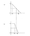
図11は、図10に示した撮像面における位置の違いによる露光量を示す図である。図11の横軸には、撮像面上の位置を示し、縦軸には、露光量を示している。
シャッタ羽根170が閉じ動作を開始すると、まず時間TAで位置Aに到達し、この位置Aでは、露光量EAだけ露光する。そのままシャッタ羽根170が移動して時間TBで位置Bに到達し、この位置Bでは、露光量EBだけ露光する。従ってこの時間TAとTBとの差が大きくなってしまうと、撮影結果に露光むらとして現れてしまうおそれがある。
FIG. 11 is a diagram illustrating an exposure amount due to a difference in position on the imaging surface illustrated in FIG. 10. The horizontal axis in FIG. 11 indicates the position on the imaging surface, and the vertical axis indicates the exposure amount.
When the
図12は、シャッタ羽根の位置と時間との関係を示す図である。図12(a)は、シャッタ羽根の移動速度を従来と同等とした場合を示し、図12(b)は、本実施例の場合を示している。
図12における縦軸に示したDは、シャッタ羽根170が移動してシャッタ閉状態となるまでに移動する距離D(=シャッタ羽根170が移動する方向の開口幅)である。なお、シャッタ羽根の移動軌跡は円弧であって、実際の移動距離は、図中のDとは異なるが、ここでは簡単のためシャッタ羽根が直線移動をすることとしている。図12(a)から、距離Dが長くなれば位置による露光むらが大きくなってしまうことが明らかであり、この距離Dができるだけ小さいことが望ましいといえる。
FIG. 12 is a diagram illustrating the relationship between the position of the shutter blade and time. FIG. 12A shows a case where the moving speed of the shutter blades is equivalent to the conventional one, and FIG. 12B shows a case of this embodiment.
D shown on the vertical axis in FIG. 12 is a distance D (= opening width in the direction in which the
そこで、本実施例では、シャッタ羽根170をシャッタ開口形状SAの短辺方向に略沿った方向に移動するようにして、他の方向に沿って移動する場合と比べて移動距離を少なくし、露光むらが少なくなるようにしている。
また、本実施例では、シャッタ羽根170の移動速度を図12(a)の場合の略倍の速度で移動させる(図12(b))ことにより、露光むらが実質的に問題にならない程度まで少なくなっている。なお、例えば、その移動距離Dが小さければ、シャッタ羽根の移動時間が実質的に短くなるので、シャッタ羽根の移動速度を速くすることが必須ではない。
さらに、シャッタ羽根を配置する位置は、可動レンズ群の可動領域の直近であることが、シャッタ羽根が撮像面のある位置に到達する光束を通過するために要する時間が長くなる(図10参照)ので、露光むらを低減するためには望ましい。よって、本実施例においても、可能な限り第2レンズ群40及び第3レンズ群50の可動領域の直近に配置した。
Therefore, in this embodiment, the
Further, in this embodiment, the moving speed of the
Furthermore, the position where the shutter blades are arranged is in the immediate vicinity of the movable region of the movable lens group, and the time required for the shutter blades to pass the light beam that reaches the position on the imaging surface becomes longer (see FIG. 10). Therefore, it is desirable to reduce exposure unevenness. Therefore, also in the present embodiment, the
実施例2は、実施例1におけるシャッタ羽根170及びシャッタ駆動部160を改良したシャッタ羽根271,272及びシャッタ駆動部260を用いている他は、実施例1と同一である。従って、前述した実施例1と同様の機能を果たす部分には、同一の符号を付して、重複する説明を適宜省略する。
図13は、シャッタ駆動部260及びシャタ羽根271,272を光軸I2に沿った方向から見た図である。図13(a)は、シャッタ閉状態を示し、図13(b)は、シャッタ開状態を示している。
実施例2では、シャッタ羽根271,272の二枚の板状部材を組み合わせて使用している。シャッタ羽根271,272は、それぞれ回転中心271a,272aを中心としてシャッタ閉状態とシャッタ開状態との間で回転可能にシャッタユニットSに取り付けられている。シャッタ羽根271,272の遮光に影響がなく回転中心271a,272aに近い位置には、溝271b,272bがそれぞれ設けられている。
The second embodiment is the same as the first embodiment except that the
FIG. 13 is a view of the
In the second embodiment, two plate-like members of
シャッタ駆動部260には、シャッタモータ261,シャッタ駆動アーム262が設けられている。シャッタ駆動アーム262は、シャッタモータ261の出力軸に取り付けられており、シャッタモータ261が回転することにより回転駆動される。シャッタ駆動アーム262の先端には、係合ピン263が設けられており、この係合ピン263がシャッタ羽根271,272の溝271b,272bに係合している。この機構により、シャッタモータ261の駆動力によってシャッタ羽根271,272をシャッタ閉状態とシャッタ開状態との間で回転駆動することができる。
The
シャッタ羽根271,272は、上述のシャッタ駆動部260によりシャッタ開口形状SAの短辺方向に略沿った方向であって、シャッタ開口形状SAの短辺方向で対向する異なる2方向において、シャッタ閉状態とシャッタ開状態との間で移動する。
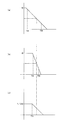
図14は、シャッタ羽根の位置と時間との関係を図12と同様にして示す図である。図14では、比較のため図12(a),図12(b)に示した図10の例の場合と実施例1の場合を図14(a),(b)にそれぞれ示し、実施例2の場合を図14(c)に示す。
先にも説明したように、シャッタ羽根の移動距離が少なくなれば、シャッタ羽根により遮光されるまでの時間の撮像面上における位置による差(時間TAとTBとの差)が少なくなり、露出むらを低減することができる。
The
FIG. 14 is a diagram showing the relationship between the position of the shutter blades and time in the same manner as in FIG. In FIG. 14, the case of FIG. 10 shown in FIGS. 12A and 12B and the case of Example 1 are shown in FIGS. 14A and 14B for comparison, respectively. This case is shown in FIG.
As described above, if the moving distance of the shutter blade is reduced, the difference in the time until the light is blocked by the shutter blade on the imaging surface (difference between the time TA and TB) is reduced, and the exposure unevenness. Can be reduced.
そこで、本実施例では、シャッタ羽根271,272の2枚のシャッタ羽根を設け、これらによりシャッタ開口形状SAの遮光する領域をそれぞれが分担するようにした。これにより、一枚のシャッタ羽根の移動距離が実施例1に比べて略半分となり、シャッタ羽根の移動時間を短縮することができる。従って、実施例1の場合のようにシャッタ羽根の移動速度を速くしなくても露光むらを実施例1と同程度まで低減することができる。シャッタ羽根の移動速度を速くした実施例1の場合には、シャッタモータ161に要求される駆動特性が高くなり、シャッタモータ161が高価になったり、大型化したりするという弊害が生じるが、本実施例によれば、そのような弊害が生じることもない。
Therefore, in this embodiment, two shutter blades,
また、図13と図9とを比較すれば明らかなように、シャッタ羽根を2枚に分けることにより、シャッタ羽根の退避スペースを一方向に大きく確保する必要がなく、効率よく退避スペースを確保することができ、全体として小型にすることができる。なお、本実施例では、シャッタ羽根を2枚としたが、これに限らず、より多くの枚数、例えば、3枚、4枚、5枚等としてもよい。シャッタ羽根の枚数を2枚よりもさらに多くすると、退避スペースにおいてシャッタ羽根を重ねることができ、より狭い退避スペースであっても成立させることができ、全体を非常に小型にすることができる。
なお、本実施例のように、シャッタ羽根をシャッタ開口形状SAの略中央部分で分けて形成した場合、画面中心付近が最も露光時間が長くなり、端部に行くに従い露光時間が短くなる。これにより露出むらとしては、画面中心について対称な形となるので、実施例1の場合と比べて、露出むらの程度が同程度であるにもかかわらず、より違和感のない映像とすることができる。
Further, as apparent from a comparison between FIG. 13 and FIG. 9, by dividing the shutter blades into two, it is not necessary to secure a large retreat space for the shutter blades in one direction, and the retreat space is efficiently secured. Can be made small as a whole. In this embodiment, the number of shutter blades is two. However, the number of shutter blades is not limited to this, and may be a larger number, for example, three, four, five, or the like. If the number of shutter blades is further increased from two, the shutter blades can be overlapped in the retreat space, and even a narrow retreat space can be established, and the whole can be made very small.
When the shutter blades are divided and formed at the substantially central portion of the shutter aperture shape SA as in this embodiment, the exposure time is the longest near the center of the screen, and the exposure time is shortened toward the end. As a result, the unevenness of exposure is symmetric with respect to the center of the screen, so that it is possible to obtain a video with a more uncomfortable feeling even though the degree of unevenness of exposure is the same as in the case of the first embodiment. .
(変形例)
以上説明した実施例に限定されることなく、種々の変形や変更が可能であって、それらも本発明の均等の範囲内である。
(1)各実施例において、シャッタユニットSを第2レンズ群40及び第3レンズ群50の可動領域とCCD90との間に配置した例を示したが、これに限らず、第2レンズ群40及び第3レンズ群50の可動領域よりも光軸に沿った方向で被写体側、例えば、第1レンズ群30と第2レンズ群40との間にシャッタユニットSを配置してもよい。
(Modification)
The present invention is not limited to the embodiments described above, and various modifications and changes are possible, and these are also within the equivalent scope of the present invention.
(1) In each of the embodiments, the example in which the shutter unit S is disposed between the movable regions of the
(2)各実施例において、プリズム20を備え、像光の方向を変えるいわゆる屈曲光学系を例に挙げて説明したが、これに限らず、プリズムを持たないストレートな光軸を持った撮影光学系であってもよい。
(2) In each of the embodiments, the so-called bending optical system that includes the
(3)各実施例において、映像を電気的に記録するデジタルカメラを例に挙げて説明したが、これに限らず、例えば、銀塩フィルムカメラのレンズ鏡筒であってもよい。 (3) In each embodiment, a digital camera that electrically records video has been described as an example. However, the present invention is not limited thereto, and for example, a lens barrel of a silver salt film camera may be used.
10:対物レンズ、20:プリズム、30:第1レンズ群、40:第2レンズ群、50:第3レンズ群、70:第4レンズ群、170,271,272:シャッタ羽根、160,260:シャッタ駆動部、S:シャッタユニット
10: objective lens, 20: prism, 30: first lens group, 40: second lens group, 50: third lens group, 70: fourth lens group, 170, 271, 272: shutter blades, 160, 260: Shutter drive unit, S: shutter unit
Claims (4)
前記撮影光学系を形成するレンズ群であって、焦点距離を変更するときに光軸に沿った方向に移動する少なくとも1つの可動レンズ群と、
を備え、
前記撮影光学系の主点位置が前記可動レンズ群の光軸に沿った方向の移動に伴い移動するレンズ鏡筒において、
前記撮影光学系を通過する撮影光束を遮断することができるシャッタ羽根を有したシャッタユニットを前記可動レンズ群の可動領域外に固定したこと、
を特徴とするカメラのレンズ鏡筒。 A photographic optical system that can change the focal length;
A lens group forming the photographing optical system, and at least one movable lens group moving in a direction along the optical axis when changing a focal length;
With
In a lens barrel in which the principal point position of the photographing optical system moves with movement in a direction along the optical axis of the movable lens group,
A shutter unit having a shutter blade capable of blocking a photographing light beam passing through the photographing optical system is fixed outside a movable region of the movable lens group;
The lens barrel of the camera.
前記シャッタ羽根が前記撮影光学系の光束を遮断する動作は、長方形の撮像領域の短辺方向に略沿った方向の動作であること、
を特徴とするカメラのレンズ鏡筒。 The lens barrel of the camera according to claim 1,
The operation in which the shutter blade blocks the light flux of the photographing optical system is an operation in a direction substantially along the short side direction of the rectangular imaging region,
The lens barrel of the camera.
前記シャッタ羽根として、前記撮影光学系の光軸に略直交する異なる方向へ各々駆動される複数枚のシャッタ羽根が設けられていること、
を特徴とするカメラのレンズ鏡筒。 In the lens barrel of the camera according to claim 1 or 2,
A plurality of shutter blades that are driven in different directions substantially perpendicular to the optical axis of the photographing optical system are provided as the shutter blades;
The lens barrel of the camera.
前記シャッタ羽根は、前記可動レンズ群の可動領域の直近に配置されていること、
を特徴とするカメラのレンズ鏡筒。
In the lens barrel of the camera according to any one of claims 1 to 3,
The shutter blade is disposed in the immediate vicinity of the movable region of the movable lens group;
The lens barrel of the camera.
Priority Applications (5)
| Application Number | Priority Date | Filing Date | Title |
|---|---|---|---|
| JP2005116755A JP2006293200A (en) | 2005-04-14 | 2005-04-14 | Lens barrel of camera |
| PCT/JP2006/307831 WO2006112353A1 (en) | 2005-04-14 | 2006-04-13 | Lens barrel |
| EP06731767A EP1870755A4 (en) | 2005-04-14 | 2006-04-13 | Lens barrel |
| CNA2006800124351A CN101160543A (en) | 2005-04-14 | 2006-04-13 | Lens barrel |
| US11/918,124 US20090041451A1 (en) | 2005-04-14 | 2006-04-13 | Lens Barrel |
Applications Claiming Priority (1)
| Application Number | Priority Date | Filing Date | Title |
|---|---|---|---|
| JP2005116755A JP2006293200A (en) | 2005-04-14 | 2005-04-14 | Lens barrel of camera |
Publications (2)
| Publication Number | Publication Date |
|---|---|
| JP2006293200A true JP2006293200A (en) | 2006-10-26 |
| JP2006293200A5 JP2006293200A5 (en) | 2008-07-03 |
Family
ID=37115076
Family Applications (1)
| Application Number | Title | Priority Date | Filing Date |
|---|---|---|---|
| JP2005116755A Pending JP2006293200A (en) | 2005-04-14 | 2005-04-14 | Lens barrel of camera |
Country Status (5)
| Country | Link |
|---|---|
| US (1) | US20090041451A1 (en) |
| EP (1) | EP1870755A4 (en) |
| JP (1) | JP2006293200A (en) |
| CN (1) | CN101160543A (en) |
| WO (1) | WO2006112353A1 (en) |
Cited By (1)
| Publication number | Priority date | Publication date | Assignee | Title |
|---|---|---|---|---|
| JP2008180774A (en) * | 2007-01-23 | 2008-08-07 | Nikon Corp | Lens barrel and digital camera |
Families Citing this family (7)
| Publication number | Priority date | Publication date | Assignee | Title |
|---|---|---|---|---|
| US7682092B2 (en) * | 2007-06-21 | 2010-03-23 | Nokia Corporation | Camera shutter assembly having casing walls for guiding a shutter and method for producing same |
| US8723922B2 (en) * | 2008-09-25 | 2014-05-13 | Sony Corporation | Single camera device and method for 3D video imaging using a refracting lens |
| JP2011048276A (en) * | 2009-08-28 | 2011-03-10 | Fujifilm Corp | Stereoscopic imaging apparatus |
| EP2604173A4 (en) * | 2011-04-26 | 2014-12-10 | Olympus Medical Systems Corp | Optical measuring device |
| JP2014179736A (en) * | 2013-03-14 | 2014-09-25 | Toshiba Corp | Camera module |
| JP6481242B2 (en) * | 2014-10-29 | 2019-03-13 | 新シコー科技株式会社 | LENS DRIVE DEVICE, CAMERA DEVICE, AND ELECTRONIC DEVICE |
| KR102651831B1 (en) * | 2021-04-05 | 2024-03-29 | 삼성전기주식회사 | Lens assembly |
Citations (9)
| Publication number | Priority date | Publication date | Assignee | Title |
|---|---|---|---|---|
| JPH07295008A (en) * | 1994-04-28 | 1995-11-10 | Nikon Corp | Image blurring correction photographing device |
| JP2000035528A (en) * | 1998-07-16 | 2000-02-02 | Nidec Copal Corp | Lens driving device |
| JP2001272711A (en) * | 2000-03-24 | 2001-10-05 | Nidec Copal Corp | Shutter blade for camera |
| JP2001281728A (en) * | 2000-03-31 | 2001-10-10 | Nidec Copal Corp | Blade chamber structure for camera |
| JP2002287004A (en) * | 2001-03-22 | 2002-10-03 | Asahi Optical Co Ltd | Lens barrel |
| JP2002344217A (en) * | 2001-05-14 | 2002-11-29 | Kojima Press Co Ltd | Antenna-tipping unit structure |
| JP2004056362A (en) * | 2002-07-18 | 2004-02-19 | Olympus Corp | Electronic imaging apparatus |
| JP2005084605A (en) * | 2003-09-11 | 2005-03-31 | Konica Minolta Opto Inc | Imaging apparatus and personal digital assistant with the apparatus |
| JP2006091405A (en) * | 2004-09-24 | 2006-04-06 | Fuji Photo Film Co Ltd | Lens barrel, imaging apparatus and optical device |
Family Cites Families (33)
| Publication number | Priority date | Publication date | Assignee | Title |
|---|---|---|---|---|
| US4724455A (en) * | 1985-01-11 | 1988-02-09 | Konishiroku Photo Industry Co., Ltd. | Exposure controlling means for a variable focus type camera |
| JP2667990B2 (en) * | 1988-07-04 | 1997-10-27 | セイコープレシジョン株式会社 | Camera system |
| US4959680A (en) * | 1988-06-29 | 1990-09-25 | Seikosha Co., Ltd. | Camera system |
| MY106892A (en) * | 1989-11-08 | 1995-08-30 | Canon Kk | Compact varifocal lens. |
| JP3360859B2 (en) * | 1993-01-26 | 2003-01-07 | 株式会社ニコン | camera |
| JPH07168231A (en) * | 1993-12-14 | 1995-07-04 | Nikon Corp | Lens barrel |
| US5680251A (en) * | 1994-01-21 | 1997-10-21 | Nikon Corporation | Lens barrel having a vibration compensation lens unit with moveable lens support member |
| US6037972A (en) * | 1994-10-21 | 2000-03-14 | Canon Kabushiki Kaisha | Camera |
| JP3379270B2 (en) * | 1995-03-02 | 2003-02-24 | 株式会社ニコン | Variable focal length lens |
| JPH09184971A (en) * | 1995-12-28 | 1997-07-15 | Olympus Optical Co Ltd | Camera with external light system automatic focusing function |
| JP2000284167A (en) * | 1999-04-01 | 2000-10-13 | Nidec Copal Corp | Lens driving mechanism equipped with vane driving mechanism |
| JP2000352657A (en) * | 1999-06-09 | 2000-12-19 | Fuji Photo Film Co Ltd | Zoom lens |
| JP2000356731A (en) * | 1999-06-15 | 2000-12-26 | Canon Inc | Bellows-like member and lens barrel provided therewith |
| JP2001350174A (en) * | 2000-06-07 | 2001-12-21 | Nisca Corp | Light quantity controller and optical apparatus incorporating the same |
| US6636362B2 (en) * | 2001-03-22 | 2003-10-21 | Pentax Corporation | Lens barrel |
| US7436599B2 (en) * | 2001-05-14 | 2008-10-14 | Olympus Corporation | Electronic image pickup system |
| JP3496667B2 (en) * | 2001-08-22 | 2004-02-16 | ミノルタ株式会社 | Zoom lens barrel |
| US6835006B2 (en) * | 2002-04-19 | 2004-12-28 | Fuji Photo Optical Co., Ltd. | Lens barrel and camera |
| JP4346008B2 (en) * | 2002-08-30 | 2009-10-14 | 元祐 高 | Method for maintaining object surface size by calculation and photographing apparatus |
| AU2003270796A1 (en) * | 2002-09-23 | 2004-04-08 | Concord Camera Corp. | Image capture device |
| US7025513B2 (en) * | 2002-11-18 | 2006-04-11 | Olympus Corporation | Optical apparatus, shutter device, and camera |
| JP2004177693A (en) * | 2002-11-27 | 2004-06-24 | Olympus Corp | Optical device and camera |
| US7019917B2 (en) * | 2002-12-03 | 2006-03-28 | Pentax Corporation | Lens barrel |
| JP2004309952A (en) * | 2003-04-10 | 2004-11-04 | Kyocera Corp | Shutter of electronic camera |
| JP4059146B2 (en) * | 2003-05-30 | 2008-03-12 | ソニー株式会社 | Zoom lens and imaging device |
| JP2005010352A (en) * | 2003-06-18 | 2005-01-13 | Konica Minolta Opto Inc | Imaging apparatus, camera equipped with imaging apparatus, and method of manufacturing lens unit |
| WO2005019925A1 (en) * | 2003-08-21 | 2005-03-03 | Olympus Corporation | Electrostatic actuator, shutter device, imaging module, and camera |
| JP3938155B2 (en) * | 2004-04-20 | 2007-06-27 | カシオ計算機株式会社 | Imaging apparatus and lens unit control method |
| JP2005326777A (en) * | 2004-05-17 | 2005-11-24 | Fujinon Corp | Lens barrel |
| JP4486428B2 (en) * | 2004-07-12 | 2010-06-23 | 日本電産コパル株式会社 | Lens drive device |
| JP2006091770A (en) * | 2004-09-27 | 2006-04-06 | Fuji Photo Film Co Ltd | Optical system unit, optical system, photographing device and optical device |
| JP4692027B2 (en) * | 2005-03-08 | 2011-06-01 | 株式会社ニコン | Image blur correction device and camera having the same |
| JP5109232B2 (en) * | 2005-03-15 | 2012-12-26 | 株式会社ニコン | Lens barrel |
-
2005
- 2005-04-14 JP JP2005116755A patent/JP2006293200A/en active Pending
-
2006
- 2006-04-13 WO PCT/JP2006/307831 patent/WO2006112353A1/en active Application Filing
- 2006-04-13 CN CNA2006800124351A patent/CN101160543A/en active Pending
- 2006-04-13 EP EP06731767A patent/EP1870755A4/en not_active Withdrawn
- 2006-04-13 US US11/918,124 patent/US20090041451A1/en not_active Abandoned
Patent Citations (9)
| Publication number | Priority date | Publication date | Assignee | Title |
|---|---|---|---|---|
| JPH07295008A (en) * | 1994-04-28 | 1995-11-10 | Nikon Corp | Image blurring correction photographing device |
| JP2000035528A (en) * | 1998-07-16 | 2000-02-02 | Nidec Copal Corp | Lens driving device |
| JP2001272711A (en) * | 2000-03-24 | 2001-10-05 | Nidec Copal Corp | Shutter blade for camera |
| JP2001281728A (en) * | 2000-03-31 | 2001-10-10 | Nidec Copal Corp | Blade chamber structure for camera |
| JP2002287004A (en) * | 2001-03-22 | 2002-10-03 | Asahi Optical Co Ltd | Lens barrel |
| JP2002344217A (en) * | 2001-05-14 | 2002-11-29 | Kojima Press Co Ltd | Antenna-tipping unit structure |
| JP2004056362A (en) * | 2002-07-18 | 2004-02-19 | Olympus Corp | Electronic imaging apparatus |
| JP2005084605A (en) * | 2003-09-11 | 2005-03-31 | Konica Minolta Opto Inc | Imaging apparatus and personal digital assistant with the apparatus |
| JP2006091405A (en) * | 2004-09-24 | 2006-04-06 | Fuji Photo Film Co Ltd | Lens barrel, imaging apparatus and optical device |
Cited By (1)
| Publication number | Priority date | Publication date | Assignee | Title |
|---|---|---|---|---|
| JP2008180774A (en) * | 2007-01-23 | 2008-08-07 | Nikon Corp | Lens barrel and digital camera |
Also Published As
| Publication number | Publication date |
|---|---|
| WO2006112353A1 (en) | 2006-10-26 |
| EP1870755A1 (en) | 2007-12-26 |
| US20090041451A1 (en) | 2009-02-12 |
| EP1870755A4 (en) | 2010-10-20 |
| CN101160543A (en) | 2008-04-09 |
Similar Documents
| Publication | Publication Date | Title |
|---|---|---|
| JP5109232B2 (en) | Lens barrel | |
| US10048507B2 (en) | Imaging apparatus | |
| US8465218B2 (en) | Aperture unit and lens barrel including the same | |
| US7768727B2 (en) | Optical lens barrel and image pickup apparatus | |
| US8026972B2 (en) | Picture-taking lens unit | |
| JP2006293200A (en) | Lens barrel of camera | |
| US7544004B2 (en) | Lens barrel and image pickup apparatus | |
| US7899312B2 (en) | Lens barrel and imaging device | |
| US9007469B2 (en) | Lens barrel and image pickup device | |
| US7808731B2 (en) | Lens guide mechanism, lens barrel, and image pickup apparatus | |
| US6222684B1 (en) | Aperture regulating apparatus | |
| JPH09269520A (en) | Image blurring correcting device | |
| JP2008164681A (en) | Lens barrel | |
| US8498060B2 (en) | Lens barrel | |
| JP5401853B2 (en) | Lens barrel and optical equipment | |
| JP2007072386A (en) | Lens barrel and photographing apparatus | |
| JPH10161194A (en) | Zoom finder | |
| JP7362377B2 (en) | Lens barrel and optical equipment including it | |
| JP2017138449A (en) | Lens barrel, optical equipment using the same and manufacturing method of lens barrel | |
| JP2013145272A (en) | Lens barrel | |
| JP6702744B2 (en) | Lens barrel and optical equipment using the same | |
| JP5897887B2 (en) | Lens barrel | |
| JPH1172690A (en) | Lens barrel | |
| CN117706848A (en) | Lens barrel | |
| JP2003287670A (en) | Lens barrel of camera |
Legal Events
| Date | Code | Title | Description |
|---|---|---|---|
| A621 | Written request for application examination |
Free format text: JAPANESE INTERMEDIATE CODE: A621 Effective date: 20080214 |
|
| A521 | Request for written amendment filed |
Free format text: JAPANESE INTERMEDIATE CODE: A523 Effective date: 20080519 |
|
| A131 | Notification of reasons for refusal |
Free format text: JAPANESE INTERMEDIATE CODE: A131 Effective date: 20100727 |
|
| A521 | Request for written amendment filed |
Free format text: JAPANESE INTERMEDIATE CODE: A523 Effective date: 20100927 |
|
| A02 | Decision of refusal |
Free format text: JAPANESE INTERMEDIATE CODE: A02 Effective date: 20101026 |