JP2006276490A - Developing device, and process cartridge and image forming apparatus using the developing device - Google Patents

Developing device, and process cartridge and image forming apparatus using the developing device Download PDF

Info

Publication number
JP2006276490A
JP2006276490A JP2005096084A JP2005096084A JP2006276490A JP 2006276490 A JP2006276490 A JP 2006276490A JP 2005096084 A JP2005096084 A JP 2005096084A JP 2005096084 A JP2005096084 A JP 2005096084A JP 2006276490 A JP2006276490 A JP 2006276490A
Authority
JP
Japan
Prior art keywords
developer
toner
chamber
developing device
storage chamber
Prior art date
Legal status (The legal status is an assumption and is not a legal conclusion. Google has not performed a legal analysis and makes no representation as to the accuracy of the status listed.)
Pending
Application number
JP2005096084A
Other languages
Japanese (ja)
Other versions
JP2006276490A5 (en
Inventor
Isao Ito
功 伊藤
Takeshi Ogoshi
竹士 大越
Current Assignee (The listed assignees may be inaccurate. Google has not performed a legal analysis and makes no representation or warranty as to the accuracy of the list.)
Fujifilm Business Innovation Corp
Original Assignee
Fuji Xerox Co Ltd
Priority date (The priority date is an assumption and is not a legal conclusion. Google has not performed a legal analysis and makes no representation as to the accuracy of the date listed.)
Filing date
Publication date
Application filed by Fuji Xerox Co Ltd filed Critical Fuji Xerox Co Ltd
Priority to JP2005096084A priority Critical patent/JP2006276490A/en
Priority to US11/245,224 priority patent/US7529509B2/en
Priority to KR1020050111775A priority patent/KR100730333B1/en
Priority to CNB2005101344939A priority patent/CN100517106C/en
Publication of JP2006276490A publication Critical patent/JP2006276490A/en
Publication of JP2006276490A5 publication Critical patent/JP2006276490A5/ja
Pending legal-status Critical Current

Links

Images

Classifications

    • GPHYSICS
    • G03PHOTOGRAPHY; CINEMATOGRAPHY; ANALOGOUS TECHNIQUES USING WAVES OTHER THAN OPTICAL WAVES; ELECTROGRAPHY; HOLOGRAPHY
    • G03GELECTROGRAPHY; ELECTROPHOTOGRAPHY; MAGNETOGRAPHY
    • G03G15/00Apparatus for electrographic processes using a charge pattern
    • G03G15/06Apparatus for electrographic processes using a charge pattern for developing
    • G03G15/08Apparatus for electrographic processes using a charge pattern for developing using a solid developer, e.g. powder developer
    • G03G15/0822Arrangements for preparing, mixing, supplying or dispensing developer
    • G03G15/0887Arrangements for conveying and conditioning developer in the developing unit, e.g. agitating, removing impurities or humidity
    • G03G15/0891Arrangements for conveying and conditioning developer in the developing unit, e.g. agitating, removing impurities or humidity for conveying or circulating developer, e.g. augers
    • G03G15/0893Arrangements for conveying and conditioning developer in the developing unit, e.g. agitating, removing impurities or humidity for conveying or circulating developer, e.g. augers in a closed loop within the sump of the developing device
    • GPHYSICS
    • G03PHOTOGRAPHY; CINEMATOGRAPHY; ANALOGOUS TECHNIQUES USING WAVES OTHER THAN OPTICAL WAVES; ELECTROGRAPHY; HOLOGRAPHY
    • G03GELECTROGRAPHY; ELECTROPHOTOGRAPHY; MAGNETOGRAPHY
    • G03G15/00Apparatus for electrographic processes using a charge pattern
    • G03G15/06Apparatus for electrographic processes using a charge pattern for developing
    • G03G15/08Apparatus for electrographic processes using a charge pattern for developing using a solid developer, e.g. powder developer
    • G03G15/0822Arrangements for preparing, mixing, supplying or dispensing developer
    • G03G15/0865Arrangements for supplying new developer
    • G03G15/0867Arrangements for supplying new developer cylindrical developer cartridges, e.g. toner bottles for the developer replenishing opening
    • G03G15/0868Toner cartridges fulfilling a continuous function within the electrographic apparatus during the use of the supplied developer material, e.g. toner discharge on demand, storing residual toner, acting as an active closure for the developer replenishing opening
    • GPHYSICS
    • G03PHOTOGRAPHY; CINEMATOGRAPHY; ANALOGOUS TECHNIQUES USING WAVES OTHER THAN OPTICAL WAVES; ELECTROGRAPHY; HOLOGRAPHY
    • G03GELECTROGRAPHY; ELECTROPHOTOGRAPHY; MAGNETOGRAPHY
    • G03G15/00Apparatus for electrographic processes using a charge pattern
    • G03G15/06Apparatus for electrographic processes using a charge pattern for developing
    • G03G15/08Apparatus for electrographic processes using a charge pattern for developing using a solid developer, e.g. powder developer
    • G03G15/0822Arrangements for preparing, mixing, supplying or dispensing developer
    • G03G15/0865Arrangements for supplying new developer
    • G03G15/0875Arrangements for supplying new developer cartridges having a box like shape
    • GPHYSICS
    • G03PHOTOGRAPHY; CINEMATOGRAPHY; ANALOGOUS TECHNIQUES USING WAVES OTHER THAN OPTICAL WAVES; ELECTROGRAPHY; HOLOGRAPHY
    • G03GELECTROGRAPHY; ELECTROPHOTOGRAPHY; MAGNETOGRAPHY
    • G03G2215/00Apparatus for electrophotographic processes
    • G03G2215/08Details of powder developing device not concerning the development directly
    • G03G2215/0802Arrangements for agitating or circulating developer material
    • G03G2215/0816Agitator type
    • G03G2215/0819Agitator type two or more agitators
    • G03G2215/0822Agitator type two or more agitators with wall or blade between agitators
    • GPHYSICS
    • G03PHOTOGRAPHY; CINEMATOGRAPHY; ANALOGOUS TECHNIQUES USING WAVES OTHER THAN OPTICAL WAVES; ELECTROGRAPHY; HOLOGRAPHY
    • G03GELECTROGRAPHY; ELECTROPHOTOGRAPHY; MAGNETOGRAPHY
    • G03G2215/00Apparatus for electrophotographic processes
    • G03G2215/08Details of powder developing device not concerning the development directly
    • G03G2215/0802Arrangements for agitating or circulating developer material
    • G03G2215/0836Way of functioning of agitator means
    • G03G2215/0838Circulation of developer in a closed loop within the sump of the developing device

Abstract

<P>PROBLEM TO BE SOLVED: To obtain a developing device capable of securing internal capacity space, keeping the conveying property of developer excellent, and achieving the supply or the recovery of fixed quantity of developer while meeting a demand that the device is miniaturized. <P>SOLUTION: In the developing device equipped with a development assisting unit for assisting a developing unit in development, the developer storing chamber 2 of the developing unit 1 and the auxiliary storing chamber 6 of the development assisting unit 5 are adjacently arranged through a partition wall 7. A dispensing chamber 8 communicating with the developer storing chamber 2 and the auxiliary storing chamber 6 so as to supply or recover the fixed quantity of developer G is formed inside the partition wall 7, and a dispensing member 9 for conveying the fixed quantity of developer is disposed in the dispensing chamber 8. The invention aims at the process cartridge and the image forming apparatus equipped with the developing device. <P>COPYRIGHT: (C)2007,JPO&INPIT

Description

本発明は、電子写真複写機やプリンタ等の画像形成装置で用いられる現像装置に係り、特に、像担持体上の静電潜像を可視像化する現像ユニットとこの現像ユニットに連通接続されて現像ユニットに対する現像補助を行う現像補助ユニットとを備えた態様の現像装置及びこれを用いたプロセスカートリッジ並びに画像形成装置の改良に関する。   The present invention relates to a developing device used in an image forming apparatus such as an electrophotographic copying machine or a printer, and in particular, is connected to a developing unit that visualizes an electrostatic latent image on an image carrier and to the developing unit. The present invention relates to a development apparatus having a development auxiliary unit for assisting development with respect to the development unit, and a process cartridge and an image forming apparatus using the development apparatus.

従来、例えば電子写真方式の画像形成装置にあっては、感光体ドラム等の像担持体上に形成された静電潜像を現像装置にてトナー現像(可視像化)し、このトナー像を転写装置にて用紙や中間転写体などの転写媒体に転写する一方、像担持体上の残留トナーをクリーニング装置にて回収する方式が通常採用されている。
そして、現像装置500としては、例えば図24又は図25に示すように、例えばトナー及びキャリアからなる現像剤が収容されて現像に供される現像ユニット510を有するが、この現像ユニット510の寿命を伸ばすために、現像ユニット510で使用された現像剤消費量に対して現像剤の補給が行われる現像剤補給ユニット520を付設したものが既に提供されている(特許文献1〜3参照)。
2. Description of the Related Art Conventionally, for example, in an electrophotographic image forming apparatus, an electrostatic latent image formed on an image carrier such as a photosensitive drum is developed with a developing device (visualized), and the toner image A system is generally employed in which the toner is transferred to a transfer medium such as a sheet or an intermediate transfer member by a transfer device, and the residual toner on the image carrier is recovered by a cleaning device.
As shown in FIG. 24 or FIG. 25, for example, the developing device 500 includes a developing unit 510 that contains a developer composed of toner and a carrier and is used for development. In order to extend, a developer replenishment unit 520 that replenishes the developer with respect to the developer consumption amount used in the development unit 510 is already provided (see Patent Documents 1 to 3).

従来この種の現像装置のうち、特許文献1に示す現像装置にあっては、現像ユニット510は、例えば図24に示すように、感光体ドラム等の像担持体501に対向する現像ハウジング511を有し、この現像ハウジング511内に例えばトナー及びキャリアからなる現像剤Gが収容される現像剤収容室512を設けると共に、この現像ハウジング511の開口に面した部位に現像ロール513を配設し、更に、現像剤収容室512内には現像剤Gが撹拌搬送される撹拌搬送オーガー514,515を配設したものである。
一方、現像剤補給ユニット520は、例えばトナー及びキャリアからなる現像剤Gが収容される補給容器521を有し、この補給容器521と現像ハウジング511とを連通ダクト522にて連通させ、現像剤収容室512内に収容される現像剤Gの上方に向かって補給容器521内の現像剤Gを自重による落下にて補給可能としたものである。
尚、図24においては、現像剤補給ユニット520は、現像剤収容室512にて劣化した現像剤Gが回収可能な回収容器530を有しており、この回収容器530と現像ハウジング511との間を連通ダクト531を介して連通させるようになっている。
Conventionally, of this type of developing device, in the developing device shown in Patent Document 1, the developing unit 510 has a developing housing 511 facing the image carrier 501 such as a photosensitive drum as shown in FIG. The developer housing 511 is provided with a developer containing chamber 512 in which a developer G made of, for example, toner and carrier is housed, and a developing roll 513 is disposed at a portion facing the opening of the developing housing 511. Further, agitating and conveying augers 514 and 515 for agitating and conveying the developer G are disposed in the developer storage chamber 512.
On the other hand, the developer replenishment unit 520 has a replenishment container 521 in which a developer G made of, for example, toner and carrier is accommodated. The replenishment container 521 and the development housing 511 are communicated with each other through a communication duct 522 to accommodate the developer. The developer G in the replenishing container 521 can be replenished by dropping due to its own weight toward the upper side of the developer G accommodated in the chamber 512.
In FIG. 24, the developer supply unit 520 has a recovery container 530 capable of recovering the developer G deteriorated in the developer storage chamber 512. Between the recovery container 530 and the development housing 511, Are communicated via a communication duct 531.

また、特許文献2,3に示す現像装置にあっては、現像ユニット510は特許文献1記載のものと略同様であるが、現像剤補給ユニット520は、図25(a)に示すように、現像ユニット510の現像ハウジング511の一部をハウジング隔壁550とする補給ハウジング541を有し、この補給ハウジング541内に補給用現像剤が収容される現像剤補給室542を設けると共に、この現像剤補給室542内に撹拌搬送用のアジテータ543を配設し、更に、この現像剤補給室542の現像ユニット510側には現像剤補給機構及び現像剤回収機構を設けたものである。
ここで、現像剤補給機構は、図25(a)(b)に示すように、通路隔壁544にて現像剤補給通路545を設けると共に、この現像剤補給通路545内に補給用オーガー546を配設し、ハウジング隔壁550に供給口547を開設したものである。但し、この供給口547は、現像剤収容室512側から現像剤Gの圧力を受けずにスムーズに現像剤を供給するために、撹拌搬送オーガー515の軸中心よりも上方、好ましくは撹拌搬送オーガー515が配設された部位の現像剤の表面位置よりも上方に設けられている。
一方、現像剤回収機構は、図25(c)に示すように、通路隔壁554にて現像剤回収通路555を設けると共に、この現像剤回収通路555内に回収用オーガー556を配設し、ハウジング隔壁550に回収口557を開設したものである。但し、この回収口557は現像剤収容室512からの現像剤の回収性を上げるために撹拌搬送オーガー515の軸中心よりも下方に設けられている。
In the developing devices shown in Patent Documents 2 and 3, the developing unit 510 is substantially the same as that described in Patent Document 1, but the developer replenishing unit 520 is as shown in FIG. A developer housing 541 having a housing partition wall 550 as a part of the developing housing 511 of the developing unit 510 is provided. In the supply housing 541, a developer supply chamber 542 in which a developer for supply is stored is provided, and the developer supply is performed. An agitator 543 for stirring and conveying is disposed in the chamber 542, and a developer replenishing mechanism and a developer collecting mechanism are provided on the developing unit 510 side of the developer replenishing chamber 542.
Here, in the developer supply mechanism, as shown in FIGS. 25A and 25B, a developer supply passage 545 is provided in the passage partition 544, and a supply auger 546 is disposed in the developer supply passage 545. The supply port 547 is opened in the housing partition wall 550. However, the supply port 547 is located above the center of the agitating / conveying auger 515, preferably the agitating / conveying auger, in order to smoothly supply the developer without receiving the developer G pressure from the developer containing chamber 512 side. It is provided above the surface position of the developer at the portion where 515 is disposed.
On the other hand, as shown in FIG. 25C, the developer recovery mechanism is provided with a developer recovery passage 555 in the passage partition 554, and a recovery auger 556 is provided in the developer recovery passage 555, and the housing A recovery port 557 is opened in the partition wall 550. However, the recovery port 557 is provided below the center of the agitating / conveying auger 515 in order to improve the recoverability of the developer from the developer storage chamber 512.

特開2001−305861号公報(発明の実施の形態、図4)Japanese Patent Laying-Open No. 2001-305861 (Embodiment of the Invention, FIG. 4) 特開平10−239970号公報(発明の実施の形態,図1)JP-A-10-239970 (Embodiment of the Invention, FIG. 1) 特開平11−44997号公報(発明の実施の形態,図1)Japanese Patent Laid-Open No. 11-44997 (Embodiment of the Invention, FIG. 1)

しかしながら、特許文献1記載の現像装置(現像剤補給ユニット520を備えた態様)にあっては、現像ユニット510と現像剤補給ユニット520との間を連結ダクト522にて連結する構造となっているため、連結ダクト522の配設スペース分だけ装置構成が大型化してしまい、小型化という要請には沿い難い。
この点、特許文献2,3記載の現像装置にあっては、現像ユニット510と現像剤補給ユニット520とをハウジング隔壁550を介して隣接配置し、現像剤補給室542のうちハウジング隔壁550に沿った部位に現像剤補給機構あるいは現像剤回収機構を配設するようにしているため、確かに現像装置の小型化を図ることは可能かも知れない。
However, in the developing device described in Patent Document 1 (a mode including the developer replenishing unit 520), the developing unit 510 and the developer replenishing unit 520 are connected by a connecting duct 522. For this reason, the apparatus configuration is increased in size by the arrangement space of the connecting duct 522, and it is difficult to meet the demand for downsizing.
In this regard, in the developing devices described in Patent Documents 2 and 3, the developing unit 510 and the developer replenishing unit 520 are disposed adjacent to each other via the housing partition 550, and along the housing partition 550 in the developer replenishing chamber 542. Since the developer replenishing mechanism or the developer collecting mechanism is arranged at the above-mentioned site, it may be possible to downsize the developing device.

ところが、特許文献2,3記載の現像装置にあっては、現像剤補給室542内の領域の一部に現像剤補給通路545あるいは現像剤回収通路555を確保し、夫々の通路545,555内に補給用オーガー546あるいは回収用オーガー556を配設する構造が採用されているため、現像剤補給室542の容量スペースを無駄に侵食するばかりか、現像剤補給室542のうちアジテータ543による搬送力が及ばない領域が生ずる等、現像剤の搬送性を阻害するという懸念がある。
尚、このような技術的課題は、トナー又はキャリアのみを補給する補給ユニットや劣化現像剤を回収するためのみの回収ユニット等の現像補助ユニットを備えた態様にあっても同様に生ずるものである。
However, in the developing devices described in Patent Documents 2 and 3, the developer supply passage 545 or the developer recovery passage 555 is secured in a part of the region in the developer supply chamber 542, and the passages 545 and 555 are provided. In the developer supply chamber 542, the capacity of the developer auger 546 or the collection auger 556 is employed, and the capacity of the developer supply chamber 542 is eroded unnecessarily. There is a concern that the transportability of the developer may be hindered, for example, an area that does not reach the threshold.
Such a technical problem similarly occurs even in a mode provided with a development auxiliary unit such as a replenishment unit that replenishes only toner or carrier or a collection unit that only collects the deteriorated developer. .

本発明は、以上の技術的課題を解決するためになされたものであって、現像ユニットに対する現像補助が行われる現像補助ユニットを備えた現像装置を前提とし、装置の小型化という要請を満たしながら、内部容量スペースを確保すると共に、現像剤の搬送性を良好に保ち、現像剤の定量供給若しくは定量回収を可能とする現像装置及びこれを用いたプロセスカートリッジ並びに画像形成装置を提供するものである。   The present invention has been made in order to solve the above technical problem, and is based on the premise of a developing device including a development auxiliary unit that performs development assistance for the development unit, while satisfying the demand for downsizing of the device. The present invention provides a developing device, a process cartridge and an image forming apparatus using the same, which secures an internal capacity space, maintains good developer transportability, and enables quantitative supply or recovery of the developer. .

すなわち、本発明は、図1(a)(b)に示すように、トナー及びキャリアからなる現像剤Gが収容される現像剤収容室2を有し、この現像剤収容室2に現像剤撹拌搬送部材3を配設すると共に、この現像剤撹拌搬送部材3にて撹拌搬送された現像剤Gが担持搬送可能な現像剤担持体4を配設した現像ユニット1と、この現像ユニット1に連通接続され、トナー及びキャリアの少なくともいずれかを含む現像剤Gが収容される補助収容室6を有し、現像ユニット1に対する現像補助を行う現像補助ユニット5とを備え、現像ユニット1の現像剤収容室2と現像補助ユニット5の補助収容室6とを隔壁7を介して隣接配置し、この隔壁7内部には、現像剤収容室2と補助収容室6とに連通して現像剤Gが定量供給可能又は定量回収可能なディスペンス室8を形成すると共に、このディスペンス室8に定量搬送用のディスペンス部材9を配設したことを特徴とする。   That is, according to the present invention, as shown in FIGS. 1 (a) and 1 (b), a developer containing chamber 2 containing a developer G composed of toner and carrier is provided, and the developer agitating chamber 2 is provided with a developer stirring chamber. A developing unit 1 provided with a conveying member 3 and a developer carrying member 4 capable of carrying and conveying the developer G stirred and conveyed by the developer agitating and conveying member 3 is communicated with the developing unit 1. A developing auxiliary unit 5 which is connected and has an auxiliary storage chamber 6 in which a developer G containing at least one of toner and carrier is stored, and which assists development with respect to the developing unit 1. The chamber 2 and the auxiliary storage chamber 6 of the development auxiliary unit 5 are disposed adjacent to each other via a partition wall 7, and the developer G is fixed in the partition wall 7 in communication with the developer storage chamber 2 and the auxiliary storage chamber 6. Disposable or quantitatively recoverable disc To form a Nsu chamber 8, characterized in that disposed dispensing member 9 for quantification conveyed to the dispensing chamber 8.

このような技術的手段において、本件は、現像ユニット1と現像補助ユニット5とを隔壁7を介して隣接配置した態様を前提とする。
現像ユニット1としては、現像剤収容室2、現像剤撹拌搬送部材(オーガー)3、現像剤担持体4を備えていればよく、他の機能部材(現像剤担持体4への供給部材や層形成部材など)については必要に応じて備えるようにすればよい。
ここで、現像剤収容室2に収容される現像剤Gはトナー及びキャリアからなる二成分現像剤である。また、この種の現像剤収容室2の好ましい態様としては、例えば現像剤担持体4の軸方向に沿って延びる仕切壁2aにて現像剤収容室2を二分すると共に、この仕切壁2aの長手方向両端に連通口2b,2cを開設することにより、現像剤収容室2に現像剤循環経路を構成し、この現像剤循環経路には一対の現像剤撹拌搬送部材3(3a,3b)を配設する態様が挙げられる。
In such technical means, the present case is premised on a mode in which the development unit 1 and the development auxiliary unit 5 are arranged adjacent to each other via the partition wall 7.
The developing unit 1 only needs to include a developer storage chamber 2, a developer agitating / conveying member (auger) 3, and a developer carrier 4. Other functional members (members and layers for supplying the developer carrier 4) A forming member or the like may be provided as necessary.
Here, the developer G accommodated in the developer accommodating chamber 2 is a two-component developer composed of toner and carrier. Further, as a preferred embodiment of this type of developer accommodating chamber 2, for example, the developer accommodating chamber 2 is divided into two by a partition wall 2a extending along the axial direction of the developer carrier 4, and the length of the partition wall 2a is By opening communication ports 2b and 2c at both ends in the direction, a developer circulation path is formed in the developer storage chamber 2, and a pair of developer agitating and conveying members 3 (3a and 3b) are arranged in the developer circulation path. The aspect to set is mentioned.

また、現像補助ユニット5は現像ユニット1に対する現像補助を行うものを広く含むものであり、現像剤供給用である態様、現像剤回収用である態様、あるいは、現像剤供給用と現像剤回収用とを兼用した態様など適宜選定して差し支えない。
ここで、現像剤供給用としては、補助収容室6にトナー及びキャリアの少なくともいずれかが含まれる新しい現像剤を予め収容し、ディスペンス室8を経由して補助収容室6の現像剤の定量供給を行う態様であればよく、代表的態様としては、トナー補給ユニット(原則的に補給用トナーを収容するものであるが、所謂トリクル方式(現像剤そのものも補給し、劣化現像剤を廃棄回収する方式)を考慮し、補給用トナーが少なくとも含まれる現像剤をも収容するものでもよい。)やキャリアを専用で供給するキャリア補給ユニットが挙げられる。
Further, the development auxiliary unit 5 includes a wide variety of units that provide development assistance to the development unit 1, an embodiment for supplying the developer, an embodiment for collecting the developer, or for supplying the developer and for collecting the developer. It is permissible to select a mode that also serves as the above.
Here, for supplying the developer, a new developer containing at least one of toner and carrier is previously stored in the auxiliary storage chamber 6, and the fixed amount of developer in the auxiliary storage chamber 6 is supplied via the dispense chamber 8. A typical mode is a toner replenishment unit (which basically stores replenishment toner, but a so-called trickle system (also replenishes the developer itself, and discards and collects the deteriorated developer). And a carrier replenishment unit that supplies a carrier exclusively.

一方、現像剤回収用としては、ディスペンス室8を経由して現像剤収容室2からの使用済み現像剤を定量回収し、補助収容室6に収容するものであればよく、代表的態様としては、使用済みの現像剤を回収する現像剤回収ユニットが挙げられる。この現像剤回収ユニットは現像剤供給用ユニットと別個に設けてもよいが、共用するものであってもよい。
更に、現像補助ユニット5としては、トナー及びキャリアの少なくともいずれかが収容される補助収容室6を備えていればよく、この補助収容室6には通常アジテータ等の現像剤搬送部材10が配設されるが、自重などで供給する態様もあるため、現像剤搬送部材10については備えていない態様も含む。また、現像補助ユニット5は単一ユニットでもよいし、複数に分かれていてもよい。
On the other hand, for collecting the developer, it is sufficient if the used developer from the developer accommodating chamber 2 is quantitatively collected via the dispensing chamber 8 and accommodated in the auxiliary accommodating chamber 6. And a developer collecting unit for collecting used developer. The developer recovery unit may be provided separately from the developer supply unit, but may be shared.
Further, the development auxiliary unit 5 only needs to include an auxiliary storage chamber 6 in which at least one of toner and carrier is stored. In the auxiliary storage chamber 6, a developer conveying member 10 such as an agitator is usually disposed. However, since there is a mode in which the developer is supplied by its own weight, a mode in which the developer conveying member 10 is not included is also included. Further, the development auxiliary unit 5 may be a single unit or may be divided into a plurality of units.

また、現像ユニット1の現像剤収容室2と現像補助ユニット5の補助収容室6とは隔壁7を介して隣接配置されていればよく、隔壁7の肉厚や形状については適宜選定して差し支えないが、隔壁7内部にディスペンス室8を確保する代表的な態様としては、現像剤収容室2と補助収容室6とを隔てる薄肉壁部を有し、この薄肉壁部の一部に厚肉壁部を設けると共に、この厚肉壁部内にディスペンス室8を形成するものが挙げられる。
ここで、ディスペンス室8は現像剤を定量供給可能又は定量回収可能とするものであればよく、通常同一断面の長尺な通路構造を採用することが多い。
更に、ディスペンス部材9はディスペンス室8での定量搬送性を実現できるものであればよく、代表的にはオーガー構成が挙げられる。
更にまた、ディスペンス室8は現像剤収容室2、補助収容室6と連通口8a,8bを介して連通していればよく、連通口8a,8bの大きさ、配設位置、数などは適宜選定して差し支えない。
Further, the developer storage chamber 2 of the developing unit 1 and the auxiliary storage chamber 6 of the development auxiliary unit 5 may be disposed adjacent to each other via a partition wall 7, and the thickness and shape of the partition wall 7 may be appropriately selected. However, as a typical mode of securing the dispensing chamber 8 inside the partition wall 7, the dispensing chamber 8 has a thin wall portion that separates the developer storage chamber 2 and the auxiliary storage chamber 6. There is one that provides a wall portion and forms the dispensing chamber 8 in the thick wall portion.
Here, the dispensing chamber 8 only needs to be capable of supplying a constant amount of developer or recovering the amount of developer, and generally employs a long passage structure having the same cross section.
Further, the dispensing member 9 may be any member that can realize the quantitative transportability in the dispensing chamber 8, and typically includes an auger configuration.
Furthermore, the dispensing chamber 8 only needs to communicate with the developer storage chamber 2 and the auxiliary storage chamber 6 through the communication ports 8a and 8b, and the size, position, number, and the like of the communication ports 8a and 8b are appropriately determined. You can choose.

また、ディスペンス室8と現像剤収容室2との好ましい連通構造としては、両者間の連通口8aは、その下端が現像剤収容室2に収容される現像剤Gの表面位置よりも下方に位置するように開口している態様が挙げられる。このように、両者間の連通口8aは現像剤収容室2の現像剤Gの表面位置から少なくとも一部が埋もれていればよく、例えば現像剤収容室2の現像剤に補給用トナーを横から供給することにより、補給トナーの現像剤への混合性を確保することができる。   Further, as a preferable communication structure between the dispensing chamber 8 and the developer storage chamber 2, the communication port 8 a between the two is positioned below the surface position of the developer G stored in the developer storage chamber 2. The mode which is opened so that it may be mentioned. In this way, the communication port 8a between the two is only required to be at least partially buried from the surface position of the developer G in the developer storage chamber 2, and for example, supply toner is supplied to the developer in the developer storage chamber 2 from the side. By supplying, it is possible to ensure the mixing property of the replenishment toner to the developer.

また、ディスペンス室8の好ましい態様としては、前記隔壁7の長手方向に沿ってもうける態様が挙げられる。この場合、ディスペンス部材9による現像剤搬送長を稼ぐことができ、省スペースでありながら、ディスペンス性能(定量供給性、定量回収性)を安定させることができる。
特に、ディスペンス室8は隔壁7の長手方向略全域に亘って設けられているのが好ましく、本態様によれば、ディスペンス部材9による現像剤搬送長を限られたスペースの中で最大化することができる。
更に、ディスペンス室8の好ましい連通構造としては、補助収容室6の連通口8bと現像剤収容室2との連通口8aとを離間配置することが好ましく、ディスペンス部材9による現像剤搬送長を稼ぐ上で有効である。
Moreover, as a preferable aspect of the dispensing chamber 8, the aspect provided along the longitudinal direction of the said partition 7 is mentioned. In this case, the developer conveyance length by the dispensing member 9 can be earned, and the dispensing performance (quantitative supply property, quantitative recovery property) can be stabilized while saving space.
In particular, it is preferable that the dispensing chamber 8 is provided over substantially the entire longitudinal direction of the partition wall 7, and according to this aspect, the developer conveyance length by the dispensing member 9 is maximized in a limited space. Can do.
Further, as a preferable communication structure of the dispensing chamber 8, it is preferable that the communication port 8b of the auxiliary storage chamber 6 and the communication port 8a of the developer storage chamber 2 are spaced apart from each other, so that the developer conveyance length by the dispensing member 9 is increased. Effective above.

また、ディスペンス機構の好ましい態様としては、隔壁7のうち薄肉壁部はディスペンス室8内のディスペンス部材9の軸方向略中心位置に沿って設けられている態様が挙げられる。本態様によれば、ディスペンス機構によって侵食されるスペースが現像剤収容室2、補助収容室6で略均等になるので、ディスペンス機構の配置に伴う各収容室2,6での現像剤の搬送性に悪影響を与えない点で好ましい。
更に、ディスペンス室8は隔壁7の任意の位置に設けて差し支えないが、隔壁7の下部に設ける態様が好ましい。この場合、補助収容室6又は現像剤収容室2からディスペンス機構に現像剤を持ち上げることなく供給又は回収することができるので、ディスペンス機構への現像剤の供給性又は回収性を安定させることが可能である。
更にまた、現像補助ユニット5を現像剤供給用として構成する場合には、補助収容室6に現像剤搬送部材10を有し、この現像剤搬送部材10の中心位置を補助収容室6とディスペンス室8との連通口8b位置よりも上方に配置することが好ましい。本態様によれば、補助収容室6からディスペンス室8まで現像剤を持ち上げる必要がないため、ディスペンス室8での現像剤内圧を損なうことなく、現像剤収容室2への現像剤補給をスムーズに行うことができる。
Moreover, as a preferable aspect of a dispensing mechanism, the aspect by which the thin wall part among the partition walls 7 is provided along the axial direction approximate center position of the dispensing member 9 in the dispensing chamber 8 is mentioned. According to this aspect, since the space eroded by the dispensing mechanism is substantially equal in the developer storage chamber 2 and the auxiliary storage chamber 6, the developer transportability in the storage chambers 2 and 6 associated with the arrangement of the dispensing mechanism. It is preferable in that it does not adversely affect.
Furthermore, although the dispensing chamber 8 may be provided at an arbitrary position of the partition wall 7, an embodiment in which the dispensing chamber 8 is provided below the partition wall 7 is preferable. In this case, since the developer can be supplied or recovered from the auxiliary storage chamber 6 or the developer storage chamber 2 to the dispensing mechanism without being lifted, it is possible to stabilize the supply or recovery of the developer to the dispensing mechanism. It is.
Furthermore, when the development auxiliary unit 5 is configured to supply developer, the auxiliary storage chamber 6 has a developer transport member 10, and the central position of the developer transport member 10 is positioned between the auxiliary storage chamber 6 and the dispense chamber. 8 is preferably disposed above the position of the communication port 8b. According to this aspect, since it is not necessary to lift the developer from the auxiliary storage chamber 6 to the dispense chamber 8, the developer supply to the developer storage chamber 2 can be smoothly performed without impairing the developer internal pressure in the dispense chamber 8. It can be carried out.

また、隔壁7の好ましい外形形態としては、補助収容室6に現像剤搬送部材10を有する態様において、隔壁7のうちディスペンス室8が囲まれる壁外側面の補助収容室6側の一部を前記現像剤搬送部材10の回転軌跡に略沿うように形成したものが挙げられ、この場合には、補助収容室6からの現像剤の搬送性を良好に保つことができる。
更に、隔壁7のうちディスペンス室8が囲まれる壁外壁面の現像剤収容室2側の一部を現像剤撹拌搬送部材3(具体的には3a)の回転軌跡に略沿うように形成したものが挙げられ、この場合には、現像剤収容室2での現像剤の搬送性を良好に保つことができる。
In addition, as a preferable external form of the partition wall 7, in the aspect in which the auxiliary transport chamber 6 includes the developer transport member 10, a part of the partition wall 7 on the side of the auxiliary storage chamber 6 on the outer wall surface surrounding the dispense chamber 8 is described above. Examples include those formed so as to substantially follow the rotation trajectory of the developer conveying member 10. In this case, the developer conveying property from the auxiliary storage chamber 6 can be kept good.
Further, a part of the outer wall surface of the partition wall 7 surrounding the dispensing chamber 8 on the developer storage chamber 2 side is formed so as to substantially follow the rotation locus of the developer stirring and conveying member 3 (specifically, 3a). In this case, the developer transportability in the developer storage chamber 2 can be kept good.

また、ディスペンス室8との連通口8a,8bには使用時に開放可能に塞がれるシール部材を設けることが好ましい。本態様によれば、シール部材によりディスペンス室8を密封することで、輸送時にディスペンス室8に現像剤が充填され、目詰まりを起こす懸念が少ない。   In addition, it is preferable to provide a sealing member that can be opened in use at the communication ports 8a and 8b with the dispensing chamber 8. According to this aspect, by sealing the dispensing chamber 8 with the seal member, the dispensing chamber 8 is filled with the developer at the time of transportation, and there is little concern about clogging.

本発明は、上述した現像装置に限られるものではなく、以下のようなプロセスカートリッジや画像形成装置にも適用可能である。
すなわち、本発明に係るプロセスカートリッジは、図1(a)に示すように、画像形成装置本体に着脱自在に装着されるプロセスカートリッジであって、像担持体15と、この像担持体15に対向配置され且つ像担持体15上の静電潜像を可視像化可能な上述した現像装置16とを含むことを特徴とするものである。
更に、本発明に係る画像形成装置は、像担持体15と、この像担持体15に対向配置され且つ像担持体15上の静電潜像を可視像化可能な上述した現像装置16とを含むものであればよく、現像装置16がプロセスカートリッジ態様であるものは勿論、プロセスカートリッジ態様でないものも含む。
The present invention is not limited to the above-described developing device, but can be applied to the following process cartridges and image forming apparatuses.
That is, as shown in FIG. 1A, the process cartridge according to the present invention is a process cartridge that is detachably attached to the main body of the image forming apparatus, and is opposed to the image carrier 15 and the image carrier 15. And the above-described developing device 16 capable of visualizing the electrostatic latent image on the image carrier 15.
Furthermore, the image forming apparatus according to the present invention includes the image carrier 15 and the above-described developing device 16 that is disposed to face the image carrier 15 and can visualize the electrostatic latent image on the image carrier 15. The developing device 16 includes not only the process cartridge mode but also the non-process cartridge mode.

本発明に係る現像装置によれば、現像ユニットの現像剤収容室と現像補助ユニットの補助収容室とを隔壁を介して隣接配置し、隔壁内部には、現像剤収容室と補助収容室とに連通して現像剤が定量的に供給可能又は回収可能なディスペンス室を形成すると共に、このディスペンス室に定量搬送用のディスペンス部材を配設したので、現像補助ユニットの補助収容室に対しディスペンス機構の配設スペースを部分的に確保する必要がなくなり、無駄なスペースや現像剤の搬送性に悪影響を与える虞れを有効に回避でき、装置の小型化に寄与することができる。   According to the developing device of the present invention, the developer storage chamber of the development unit and the auxiliary storage chamber of the development auxiliary unit are disposed adjacent to each other via the partition, and the developer storage chamber and the auxiliary storage chamber are provided inside the partition. Since a dispensing chamber is formed in which the developer can be quantitatively supplied or collected and a dispensing member for quantitative conveyance is disposed in the dispensing chamber, the dispensing mechanism is connected to the auxiliary storage chamber of the developing auxiliary unit. It is not necessary to partially secure the installation space, and it is possible to effectively avoid the possibility of adversely affecting the useless space and developer transportability, thereby contributing to downsizing of the apparatus.

また、このような現像装置を用いたプロセスカートリッジ又は画像形成装置によれば、現像装置の小型化を図りながら、現像剤の定量供給性又は定量回収性が良好なプロセスカートリッジ又は画像形成装置を簡単に構築することができる。   In addition, according to the process cartridge or the image forming apparatus using such a developing device, it is possible to simplify the process cartridge or the image forming device having good developer quantitative supply ability or quantitative recoverability while reducing the size of the developing apparatus. Can be built.

以下、添付図面に示す実施の形態に基づいてこの発明を詳細に説明する。
◎実施の形態1
<画像形成装置の全体構成>
図2は、本発明が適用された画像形成装置の実施の形態1を示す。
同図において、画像形成装置は所謂タンデム型のカラー画像形成装置であり、装置筐体21内に4つの色(本実施の形態ではイエロ、マゼンタ、シアン、ブラック)の画像形成ユニット22(具体的には22a〜22d)を縦方向に配列し、その下方には供給用の用紙24が収容される給紙カセット23を配設すると共に、各画像形成ユニット22に対応した箇所には給紙カセット23からの用紙24の搬送路となる用紙搬送路25を垂直方向に配置したものである。
Hereinafter, the present invention will be described in detail based on embodiments shown in the accompanying drawings.
Embodiment 1
<Overall configuration of image forming apparatus>
FIG. 2 shows Embodiment 1 of an image forming apparatus to which the present invention is applied.
In the figure, the image forming apparatus is a so-called tandem type color image forming apparatus, and an image forming unit 22 (specifically, yellow, magenta, cyan, and black in this embodiment) is provided in the apparatus housing 21. 22a to 22d) are arranged in the vertical direction, and a paper feed cassette 23 for storing paper 24 for supply is arranged below the paper feed cassette 23, and a paper feed cassette is provided at a position corresponding to each image forming unit 22. 23, a sheet conveyance path 25 serving as a conveyance path for the sheet 24 from 23 is arranged in the vertical direction.

本実施の形態において、画像形成ユニット22(22a〜22d)は、用紙搬送路25の上流側から順に、イエロ用、マゼンタ用、シアン用、ブラック用のトナー像を形成するものであり、各種プロセスユニットを組み込んだプロセスカートリッジ30と、このプロセスカートリッジ30に対して作像用の走査光を照射する露光装置40とを備えている。
ここで、プロセスカートリッジ30は、例えば感光体ドラム31と、この感光体ドラム31を予め帯電する帯電ロール32と、帯電された感光体ドラム31上に前記露光装置40にて露光形成された静電潜像を対応する色トナー(本実施の形態では例えば負極性)で現像する現像装置33と、感光体ドラム31上の廃トナーを除去するクリーニング装置34と、帯電された感光体ドラム31の表面を除電するイレーズランプ35とを一体的にカートリッジ化したものである。
一方、露光装置40は、ケース41内に図示外の半導体レーザ、ポリゴンミラー42、結像レンズ43及びミラー44を格納し、半導体レーザからの光をポリゴンミラー42で偏向走査し、結像レンズ43、ミラー44を介して感光体ドラム31上の露光ポイントに光像を導くようにしたものである。
In the present embodiment, the image forming units 22 (22a to 22d) form toner images for yellow, magenta, cyan, and black in order from the upstream side of the sheet conveyance path 25, and various processes. A process cartridge 30 incorporating the unit and an exposure device 40 for irradiating the process cartridge 30 with scanning light for image formation are provided.
Here, the process cartridge 30 includes, for example, a photosensitive drum 31, a charging roll 32 that precharges the photosensitive drum 31, and an electrostatic device that is exposed and formed by the exposure device 40 on the charged photosensitive drum 31. A developing device 33 that develops the latent image with corresponding color toner (for example, negative polarity in the present embodiment), a cleaning device 34 that removes waste toner on the photosensitive drum 31, and a surface of the charged photosensitive drum 31 An erase lamp 35 that neutralizes the charge is integrated into a cartridge.
On the other hand, the exposure apparatus 40 stores a semiconductor laser (not shown), a polygon mirror 42, an imaging lens 43 and a mirror 44 in the case 41, and deflects and scans the light from the semiconductor laser with the polygon mirror 42. The optical image is guided to the exposure point on the photosensitive drum 31 through the mirror 44.

更に、本実施の形態では、各画像形成ユニット22の各感光体ドラム31に対応した箇所には用紙搬送路25に沿って循環移動する搬送ベルト53が配設されている。
この搬送ベルト53は用紙24を静電吸着し得るベルト素材(ゴム又は樹脂)にて構成され、一対の張架ロール51,52に掛け渡されており、本実施の形態では、上方側の張架ロール52が駆動ロール、下方側の張架ロール51が従動ロールになっている。
Further, in the present embodiment, a conveyance belt 53 that circulates along the sheet conveyance path 25 is disposed at a position corresponding to each photosensitive drum 31 of each image forming unit 22.
The conveyor belt 53 is made of a belt material (rubber or resin) that can electrostatically attract the paper 24, and is stretched between a pair of tension rolls 51 and 52. The rack roll 52 is a driving roll, and the lower tension roll 51 is a driven roll.

更にまた、搬送ベルト53の入口部位(張架ロール51対向部位)には用紙吸着ロール54が配設されており、この用紙吸着ロール54に高電圧な吸着電圧を印加することにより、搬送ベルト53に用紙24が吸着されるようになっている。また、各画像形成ユニット22の感光体ドラム31に対応した搬送ベルト53の裏面側には転写ロール50が配設されており、この転写ロール50により感光体ドラム31と搬送ベルト53上の用紙24とを密着させるようになっている。そして、転写ロール50と感光体ドラム31との間には転写バイアス電源による所定の転写バイアスが適宜印加されるようになっている。   Furthermore, a paper suction roll 54 is disposed at the entrance portion of the transport belt 53 (the portion facing the stretching roll 51). By applying a high voltage suction voltage to the paper suction roll 54, the transport belt 53 is provided. The sheet 24 is attracted to the sheet. Further, a transfer roll 50 is disposed on the back side of the conveyance belt 53 corresponding to the photosensitive drum 31 of each image forming unit 22, and the sheet 24 on the photosensitive drum 31 and the conveyance belt 53 is transferred by the transfer roll 50. And come to stick. A predetermined transfer bias by a transfer bias power source is appropriately applied between the transfer roll 50 and the photosensitive drum 31.

また、本実施の形態では、給紙カセット23の近傍には、用紙24を所定のタイミングで送出するピックアップロール61が設けられており、搬送ロール62及びレジストレーションロール63を介して転写位置へと送り込むようになっている。
更に、最下流画像形成ユニット22dの下流側に位置する用紙搬送路25には定着装置64が設けられると共に、この定着装置64の下流側には用紙排出用の排出ロール66が設けられており、装置筐体21の上部に形成された収容トレイ67に排出用紙が収容されるようになっている。
尚、図2中、符号80は高圧用の装置デバイスに高電圧を供給する高圧電源を示し、符号81は低圧用の装置デバイスに低電圧を供給する低圧電源を示す。
In the present embodiment, a pickup roll 61 is provided in the vicinity of the paper feed cassette 23 to feed the paper 24 at a predetermined timing. The pickup roll 61 is moved to the transfer position via the transport roll 62 and the registration roll 63. It comes to send.
Further, a fixing device 64 is provided in the paper conveyance path 25 located on the downstream side of the most downstream image forming unit 22d, and a discharge roll 66 for discharging paper is provided on the downstream side of the fixing device 64. The discharged paper is stored in a storage tray 67 formed on the upper portion of the apparatus housing 21.
In FIG. 2, reference numeral 80 denotes a high-voltage power supply that supplies a high voltage to the high-voltage device, and reference numeral 81 denotes a low-voltage power supply that supplies a low voltage to the low-voltage device.

このような、画像形成装置の作像プロセスは以下の通りである。
今、図2に示すように、各画像形成ユニット22(22a〜22d)では、感光体ドラム31が帯電ロール32により帯電され、露光装置40により感光体ドラム31上に潜像が形成された後に、現像装置33により可視像(トナー像)が形成される。
一方、給紙カセット23からの用紙24は、ピックアップロール61にて所定のタイミングで繰り出され、搬送ロール62及びレジストレーションロール63を介して搬送ベルト53の吸着位置へと送り込まれ、搬送ベルト53に吸着された状態で転写位置へと送り込まれるようになっている。
そして、各画像形成ユニット22における感光体ドラム31上のトナー像は転写ロール50により用紙24に夫々転写され、定着装置64にて用紙24上の各色成分未定着トナー像が定着された後、定着済みの用紙24は収容トレイ67へ排出される。
The image forming process of such an image forming apparatus is as follows.
As shown in FIG. 2, in each image forming unit 22 (22 a to 22 d), after the photosensitive drum 31 is charged by the charging roll 32 and a latent image is formed on the photosensitive drum 31 by the exposure device 40. A visible image (toner image) is formed by the developing device 33.
On the other hand, the paper 24 from the paper feed cassette 23 is fed out at a predetermined timing by the pickup roll 61, sent to the suction position of the transport belt 53 through the transport roll 62 and the registration roll 63, and is fed to the transport belt 53. It is sent to the transfer position in the adsorbed state.
Then, the toner images on the photosensitive drum 31 in each image forming unit 22 are respectively transferred to the paper 24 by the transfer roll 50, and each color component unfixed toner image on the paper 24 is fixed by the fixing device 64 and then fixed. The used paper 24 is discharged to the storage tray 67.

<プロセスカートリッジの概要>
また、本実施の形態で用いられるプロセスカートリッジ30の詳細を図3に示す。
同図において、プロセスカートリッジ30は、感光体ドラム31、帯電ロール32、現像装置33の一部、クリーニング装置34のほかに、クリーニング処理前に感光体ドラム31を除電するデバイスとしてのイレーズランプ35が含まれる感光体カートリッジ30aと、この感光体カートリッジ30aの下方側に前記感光体カートリッジ30aに対して揺動自在で且つ位置決めされた状態で設けられると共に現像装置33の主要部が含まれる現像カートリッジ30bとを備えている。
<Outline of process cartridge>
FIG. 3 shows details of the process cartridge 30 used in the present embodiment.
In the figure, a process cartridge 30 includes a photosensitive drum 31, a charging roll 32, a part of a developing device 33, a cleaning device 34, and an erase lamp 35 as a device for discharging the photosensitive drum 31 before the cleaning process. A photosensitive cartridge 30a included, and a developing cartridge 30b provided below the photosensitive cartridge 30a so as to be swingable and positioned with respect to the photosensitive cartridge 30a and including a main part of the developing device 33. And.

特に、本実施の形態では、現像装置33は、感光体ドラム31に対向し且つ感光体ドラム31上の静電潜像をトナー及びキャリアからなる現像剤Gにて可視像化する現像ユニット100と、この現像ユニット100に対してトナーTを補給するトナー補給ユニット110,120(本実施の形態では、メイントナー補給ユニット110、サブトナー補給ユニット120との分離型を採用)とを備えている。
そして、感光体カートリッジ30aはクリーニング装置34をユニット化したクリーニングユニット200とサブトナー補給ユニット120とを横方向に一体化した構成になっており、また、現像カートリッジ30bは現像ユニット100とメイントナー補給ユニット110とを横方向に一体化した構成になっている。
In particular, in the present embodiment, the developing device 33 faces the photosensitive drum 31 and visualizes the electrostatic latent image on the photosensitive drum 31 with a developer G composed of toner and carrier. And toner replenishing units 110 and 120 for replenishing toner T to the developing unit 100 (in this embodiment, a separate type from the main toner replenishing unit 110 and the sub toner replenishing unit 120 is employed).
The photosensitive cartridge 30a has a configuration in which a cleaning unit 200 in which the cleaning device 34 is unitized and a sub-toner replenishment unit 120 are integrated in the horizontal direction, and the development cartridge 30b has a development unit 100 and a main toner replenishment unit. 110 is integrated in the horizontal direction.

更に、本実施の形態では、現像カートリッジ30bは装置筐体21に位置決め固定された感光体カートリッジ30aに対し現像ユニット100部位にピボット軸30cにて揺動自在に設けられており、感光体カートリッジ30aと現像カートリッジ30bとの間には露光装置40からの走査光が通過可能な走査用通路135が確保され、この走査用通路135の入口付近の各パーツカートリッジ30a,30bの両側には弾性部材からなるスペーサ130が介在され、感光体カートリッジ30aに対して現像カートリッジ30bを加圧付勢するようになっている。尚、スペーサ130に代えて、あるいは、加えて付勢スプリング等の付勢要素を用いるようにしてもよいことは勿論である。   Further, in the present embodiment, the developing cartridge 30b is provided at the developing unit 100 portion so as to be swingable by the pivot shaft 30c with respect to the photosensitive cartridge 30a positioned and fixed to the apparatus housing 21, and the photosensitive cartridge 30a. A scanning passage 135 through which scanning light from the exposure device 40 can pass is secured between the developing cartridge 30b and an elastic member on both sides of each part cartridge 30a, 30b near the entrance of the scanning passage 135. A spacer 130 is interposed to pressurize the developing cartridge 30b against the photosensitive cartridge 30a. Of course, a biasing element such as a biasing spring may be used instead of or in addition to the spacer 130.

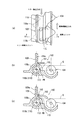
また、本実施の形態では、感光体カートリッジ30aのサブトナー補給ユニット120には、図3及び図4(a)(b)に示すように、感光体ドラム31の軸方向に直交する方向に延びる例えば一対の支持突起141が設けられている。
そして、装置筐体21のカートリッジ受部(図示せず)にプロセスカートリッジ30を装着した時に、感光体ドラム31を回転自在に支承する支持軸の両端が、カートリッジ受部に設けられた図示外の固定受け部材により所定の位置に固定されると共に、該支持軸に回転自在に配設された該感光体ドラム31の片端に配設された駆動伝達部材(例えば駆動伝達ギア)が、カートリッジ受部に設けられた図示外の駆動系に連結係合する。また、前記一対の支持突起141がカートリッジ受部の被係合部(凹部や孔等)に係合し、感光体カートリッジ30aが装置筐体21に位置決め固定されるようになっている。ここで、装置筐体21のカートリッジ受部はプロセスカートリッジ30を収容保持できるものであればよく、筐体フレーム自体を用いて構成してもよいし、筐体フレームに別部材を設けて構成してもよい。
特に、本実施の形態にあっては、前記支持突起141は、感光体ドラム31から離れたユニット外壁に設けられると共に、感光体ドラム31を駆動する駆動力による、該プロセスカートリッジ30の回転を抑える機能も有している。
尚、図4中、符号142はプロセスカートリッジ30を着脱操作する際の把持アームである。
In the present embodiment, the sub-toner replenishment unit 120 of the photoconductor cartridge 30a extends in a direction orthogonal to the axial direction of the photoconductor drum 31, as shown in FIGS. 3 and 4A and 4B, for example. A pair of support protrusions 141 are provided.
Then, when the process cartridge 30 is mounted in a cartridge receiving portion (not shown) of the apparatus housing 21, both ends of the support shaft that rotatably supports the photosensitive drum 31 are not shown in the drawing provided in the cartridge receiving portion. A drive transmission member (for example, a drive transmission gear) disposed at one end of the photosensitive drum 31 that is fixed at a predetermined position by the fixed receiving member and is rotatably disposed on the support shaft is a cartridge receiving portion. It is connected and engaged with a drive system (not shown) provided in The pair of support protrusions 141 are engaged with engaged portions (such as recesses and holes) of the cartridge receiving portion so that the photosensitive cartridge 30 a is positioned and fixed to the apparatus housing 21. Here, the cartridge receiving portion of the apparatus housing 21 may be any as long as it can accommodate and hold the process cartridge 30, and may be configured using the housing frame itself, or may be configured by providing another member on the housing frame. May be.
In particular, in the present embodiment, the support protrusion 141 is provided on the outer wall of the unit away from the photosensitive drum 31 and suppresses the rotation of the process cartridge 30 due to the driving force that drives the photosensitive drum 31. It also has a function.
In FIG. 4, reference numeral 142 denotes a gripping arm used when the process cartridge 30 is attached and detached.

<現像装置>
本実施の形態で用いられる現像装置33を構成する各ユニット100,110,120について説明する。
−現像ユニット−
本実施の形態において、現像ユニット100は、図3、図5及び図6に示すように、所謂二成分現像方式を採用したものであって、感光体ドラム31の下方側には感光体ドラム31側に開口する現像ハウジング101を有し、この現像ハウジング101内をトナー及びキャリアからなる現像剤Gが収容可能な現像剤収容室102として構成すると共に、現像ハウジング101の開口に面した部位に現像剤担持用の現像ロール103を配設したものである。そして、この現像ユニット100は、現像ロール103の軸方向に沿って延びる仕切壁106にて現像剤収容室102を二分すると共に、この仕切壁106の長手方向両端に連通口107,108を開設することにより、現像剤収容室102に現像剤循環経路を構成し、この現像剤循環経路には現像ロール103の軸方向に沿って一対の撹拌搬送オーガー104,105を配設し、現像剤循環経路内の現像剤Gを撹拌しながら搬送するようになっている。
ここで、撹拌搬送オーガー104は既存の現像剤Gに専ら補給されたトナーTを撹拌混合することを主眼としたアドミックスオーガーであり、一方、撹拌搬送オーガー105は前記トナーの撹拌混合機能に加えて現像ロール103への現像剤供給機能を担ったサプライオーガーである。
尚、本実施の形態では、現像ロール103寄りの撹拌搬送オーガー105が現像ロール103への現像剤供給機能を兼用しているが、撹拌搬送オーガー105とは別に現像剤供給部材(ロールやパドル等)を付加してもよいことは勿論である。また、現像ロール103の周囲には現像剤層厚を規制するトリミング部材や未使用現像剤を回収する回収部材などが必要に応じて設けられる。
<Developing device>
The units 100, 110, and 120 constituting the developing device 33 used in this embodiment will be described.
-Development unit-
In the present embodiment, the developing unit 100 employs a so-called two-component developing system as shown in FIGS. 3, 5, and 6, and the photosensitive drum 31 is disposed below the photosensitive drum 31. The developing housing 101 is open to the side, and the developing housing 101 is configured as a developer containing chamber 102 in which a developer G composed of toner and carrier can be stored, and development is performed at a portion facing the opening of the developing housing 101. A developing roll 103 for supporting the agent is disposed. The developing unit 100 bisects the developer accommodating chamber 102 with a partition wall 106 extending along the axial direction of the developing roll 103, and opens communication ports 107 and 108 at both longitudinal ends of the partition wall 106. As a result, a developer circulation path is formed in the developer storage chamber 102, and a pair of agitation transport augers 104 and 105 are disposed along the axial direction of the developing roll 103 in this developer circulation path. The developer G inside is conveyed while stirring.
Here, the agitating / conveying auger 104 is an admix auger whose main purpose is to agitate and mix the toner T replenished exclusively to the existing developer G. On the other hand, the agitating / conveying auger 105 is added to the agitating and mixing function of the toner. This is a supply auger responsible for the developer supply function to the developing roll 103.
In this embodiment, the agitating / conveying auger 105 near the developing roll 103 also serves as a developer supplying function to the developing roll 103. However, a developer supplying member (roll, paddle, etc.) is provided separately from the agitating / conveying auger 105. Of course, it may be added. Further, a trimming member for regulating the developer layer thickness, a collecting member for collecting unused developer, and the like are provided around the developing roll 103 as necessary.

−メイントナー補給ユニット−
また、メイントナー補給ユニット110は、図3、図5及び図6に示すように、現像ユニット100の現像ハウジング101の奥側隔壁109を一部兼用するメイン補給ハウジング111を有し、このメイン補給ハウジング111内を補給用トナーTが補給可能に収容されるトナー補給室として構成するようになっている。
特に、本実施の形態では、トナー補給室は、補給用トナーTが収容されるトナー収容室112と、このトナー収容室112と連通し且つ現像ユニット100に対してトナーTを定量的に補給するディスペンス室113とに分かれている。ここで、現像ハウジング101の奥側隔壁109は薄肉壁部109aを有し、この薄肉壁部109aの下部寄りに末広がり状の厚肉壁部109bを設けたものである。そして、ディスペンス室113は現像ハウジング101の奥側隔壁109の下部寄りに厚肉壁部109bを設け、この厚肉壁部109b内に現像ロール103の軸方向に沿って延びる断面略円形の長尺通路(トンネル状通路)として構成されている。
そして、前記厚肉壁部109bの長手方向奥側のうちトナー収容室112に面した部位にはディスペンス入口開口114が開設される一方、厚肉壁部109bのうち現像剤収容室102に面した部位で前記ディスペンス入口開口114とは長手方向反対側にはトナー供給口115が開設されている。
-Main toner supply unit-
Further, as shown in FIGS. 3, 5 and 6, the main toner replenishment unit 110 has a main replenishment housing 111 which also serves as a part of the rear partition 109 of the developing housing 101 of the developing unit 100. The housing 111 is configured as a toner replenishing chamber in which replenishing toner T is accommodated so as to be replenished.
In particular, in the present embodiment, the toner supply chamber communicates with the toner storage chamber 112 in which the supply toner T is stored, and the toner storage chamber 112, and quantitatively supplies the toner T to the developing unit 100. It is divided into a dispensing chamber 113. Here, the rear partition 109 of the developing housing 101 has a thin wall portion 109a, and a thick wall portion 109b having a divergent shape is provided near the lower portion of the thin wall portion 109a. The dispensing chamber 113 is provided with a thick wall portion 109b near the lower portion of the rear partition 109 of the developing housing 101, and has a substantially circular cross section extending along the axial direction of the developing roll 103 in the thick wall portion 109b. It is configured as a passage (tunnel-shaped passage).
A dispensing inlet opening 114 is opened in a portion facing the toner storage chamber 112 on the inner side in the longitudinal direction of the thick wall portion 109b, while facing the developer storage chamber 102 in the thick wall portion 109b. A toner supply port 115 is opened on the side opposite to the dispensing inlet opening 114 in the longitudinal direction.

更に、トナー収容室112内には補給用トナーTを撹拌搬送するためのアジテータ116と、このアジテータ116にて撹拌搬送されたトナーTをディスペンス室113のディスペンス入口開口114に向けて撹拌搬送するアジテータ117とが配設されている。
ここで、アジテータ116はクランク状の回転ロッド401の先端にPETフィルム等からなるアジテートフィルム402を有し、このアジテートフィルム402にてトナーをトナー補給室壁面に沿って搬送するものである。そして、回転ロッド401のアジテータフィルム402の反対側には回転ロッド401の径方向に延びる適宜数の撹拌ロッド403が設けられ、トナー補給室内のトナーを撹拌するようになっている。また、アジテータ117はアジテータ116と略同様に構成して差し支えないが、例えばアジテートフィルムに適宜切り込みを設けるなどしてディスペンス入口開口114に向けてトナー搬送方向を調整するようにすることが好ましい。但し、アジテータ116,117としては撹拌搬送オーガーなどを用いるようにしてもよいことは勿論である。
尚、図6中、アジテータ116,117の形態は模式的に示されている。
一方、ディスペンス室113には長手方向に沿ってディスペンスオーガー118が配設されている。特に、本実施の形態では、ディスペンスオーガー118は現像ユニット100内の撹拌搬送オーガー104,105と略同径かそれ以下の螺旋羽根を備えたものになっており、更に、ディスペンスオーガー118のピッチが撹拌搬送オーガー104,105のピッチ以下に設定されている。
Further, an agitator 116 for agitating and conveying the replenishing toner T in the toner storage chamber 112, and an agitator for agitating and conveying the toner T agitated and conveyed by the agitator 116 toward the dispensing inlet opening 114 of the dispensing chamber 113. 117 is disposed.
Here, the agitator 116 has an agitate film 402 made of a PET film or the like at the tip of a crank-shaped rotating rod 401, and the agitator film 402 conveys toner along the wall of the toner supply chamber. An appropriate number of stirring rods 403 extending in the radial direction of the rotating rod 401 are provided on the opposite side of the rotating rod 401 from the agitator film 402 so as to stir the toner in the toner supply chamber. The agitator 117 may be configured in substantially the same manner as the agitator 116, but it is preferable to adjust the toner conveyance direction toward the dispense inlet opening 114 by, for example, appropriately cutting the agitate film. However, as agitator 116, 117, it is needless to say that a stirring conveyance auger or the like may be used.
In FIG. 6, the form of the agitators 116 and 117 is schematically shown.
On the other hand, a dispense auger 118 is disposed in the dispense chamber 113 along the longitudinal direction. In particular, in the present embodiment, the dispense auger 118 is provided with a spiral blade having a diameter substantially equal to or less than that of the agitating / conveying augers 104 and 105 in the developing unit 100, and the pitch of the dispense auger 118 is further increased. The pitch is set below the pitch of the agitating and conveying augers 104 and 105.

更に、本実施の形態では、隔壁109のうち薄肉壁部109aはディスペンス室113内のディスペンスオーガー118の軸方向略中央に沿って設けられており、ディスペンス機構(ディスペンス室113,ディスペンスオーガー118)によって侵食されるスペースが現像剤収容室102、トナー収容室112で略均等に配分されている。このため、ディスペンス機構の配置に伴う各収容室102,112での現像剤若しくはトナーの搬送性に悪影響を与えない。
また、ディスペンス室113が囲まれる厚肉壁部109bの外側面のうちトナー収容室112側の一部は、アジテータ117の回転軌跡(具体的にはアジテータフィルム142先端の回転軌跡に相当)に略沿うように形成されており、トナー収容室112でのトナーの搬送性が良好に保たれるようになっている。
そしてまた、厚肉壁部109bの外側面のうち現像剤収容室102側の一部は、アドミックスオーガー104の回転軌跡に沿うように形成されており、現像剤収容室102での現像剤の搬送性が良好に保たれるようになっている。
そして、本実施の形態では、隔壁109の厚肉壁部109bの外壁面はアジテータ117、撹拌搬送オーガー104の軸方向に沿って略平行に延びる滑らかな面として構成されているため、この隔壁109の厚肉壁部109bの外壁面に局部的な凹所が設けられるという懸念は全くなく、トナー収容室112、現像剤収容室102の隔壁109近傍にトナーや現像剤が搬送されずに滞留するという事態は有効に回避される。
Furthermore, in the present embodiment, the thin wall portion 109a of the partition wall 109 is provided along substantially the center in the axial direction of the dispense auger 118 in the dispense chamber 113, and is dispensed by the dispense mechanism (the dispense chamber 113, the dispense auger 118). The space to be eroded is distributed substantially evenly in the developer storage chamber 102 and the toner storage chamber 112. For this reason, the developer or toner transportability in each of the storage chambers 102 and 112 due to the arrangement of the dispensing mechanism is not adversely affected.
In addition, a part of the outer surface of the thick wall portion 109b surrounded by the dispense chamber 113 on the toner storage chamber 112 side is substantially a rotation locus of the agitator 117 (specifically, corresponds to a rotation locus of the tip of the agitator film 142). It is formed so that the toner transportability in the toner storage chamber 112 is kept good.
Further, a part of the outer side surface of the thick wall portion 109b on the developer storage chamber 102 side is formed along the rotation locus of the admix auger 104, and the developer in the developer storage chamber 102 Good transportability is maintained.
In the present embodiment, the outer wall surface of the thick wall portion 109b of the partition wall 109 is configured as a smooth surface extending substantially in parallel along the axial direction of the agitator 117 and the agitating / conveying auger 104. There is no concern that a local recess is provided on the outer wall surface of the thick wall portion 109b, and toner and developer stay in the vicinity of the partition wall 109 of the toner storage chamber 112 and the developer storage chamber 102 without being conveyed. This situation is effectively avoided.

また、本実施の形態では、トナー供給口115は、図7(a)(b)に示すように、その下端が現像剤収容室102に収容される現像剤Gの表面位置より下方に位置するように開口している。すなわち、トナー供給口115は現像剤収容室102の現像剤Gの表面位置から少なくとも埋もれていればよく、現像剤収容室102の現像剤に補給用トナーTを横から供給可能とし、現像剤G上に補給用トナーTを浮き上がらせることなく、補給用トナーTの現像剤への撹拌混合性を確保するようになっている。
特に、本実施の形態では、トナー補給ユニット110内の補給用トナーTがトナー供給口115から押し出される押圧力が現像剤収容室102の現像剤Gによる内圧よりも大きく設定されている。
具体的には、ディスペンス入口開口114がトナー供給口115よりも広く形成され、また、ディスペンス室113の長手方向長がディスペンス入口開口114よりも充分長く設定されている。更に、アジテータ117によるディスペンス入口開口114へのトナー供給量はディスペンスオーガー118によるトナー搬送量(トナー供給口115から排出されるトナー供給量に相当)より多く設定されている。
更にまた、ディスペンスオーガー118の径寸法や羽根ピッチ、回転数などについては、ディスペンスオーガー118によるトナーの搬送力に基づくトナー内圧がトナー供給口115にかかる現像剤収容室102内の現像剤Gの内圧(撹拌搬送オーガー104の搬送力に依存)に比べて大きくなるように選定されている。
In the present embodiment, as shown in FIGS. 7A and 7B, the lower end of the toner supply port 115 is located below the surface position of the developer G stored in the developer storage chamber 102. So that it is open. That is, the toner supply port 115 only needs to be buried at least from the surface position of the developer G in the developer storage chamber 102, and the replenishment toner T can be supplied from the side to the developer in the developer storage chamber 102. The replenishing toner T is secured to the developer without causing the replenishing toner T to rise above.
In particular, in this embodiment, the pressing force by which the replenishing toner T in the toner replenishing unit 110 is pushed out from the toner supply port 115 is set to be larger than the internal pressure by the developer G in the developer storage chamber 102.
Specifically, the dispense inlet opening 114 is formed wider than the toner supply opening 115, and the longitudinal length of the dispense chamber 113 is set sufficiently longer than the dispense inlet opening 114. Furthermore, the amount of toner supplied to the dispense inlet opening 114 by the agitator 117 is set to be larger than the amount of toner transported by the dispense auger 118 (corresponding to the amount of toner supplied from the toner supply port 115).
Furthermore, regarding the diameter size, blade pitch, rotation speed, and the like of the dispense auger 118, the internal pressure of the developer G in the developer storage chamber 102 applied to the toner supply port 115 is based on the toner internal pressure based on the toner conveying force by the dispense auger 118. It is selected to be larger than (depends on the conveying force of the agitating / conveying auger 104).

また、本実施の形態では、図7(a)(b)に示すように、ディスペンスオーガー118は通常の撹拌搬送用のオーガー羽根118aのほかに、トナー供給口115に面した部位にせき止め用のオーガー羽根118bを有しており、このせき止め用のオーガー羽根118bが押出部PSとして働き、この押出部PSによりせき止められたトナーTがトナー供給口115から現像剤収容室102へと押し出されるようになっている。
尚、本実施の形態では、トナー供給口115は、現像剤収容室102の端部位置から離れた位置に開口しているが、前記せき止め用のオーガー羽根118bによる押し出し作用にてトナー供給口115から補給用トナーTが押し出される。
Further, in the present embodiment, as shown in FIGS. 7A and 7B, the dispense auger 118 is used for preventing clogging at a portion facing the toner supply port 115 in addition to an auger blade 118a for normal stirring and conveying. The auger blade 118b for preventing clogging functions as an extruding portion PS, and the toner T blocked by the extruding portion PS is pushed out from the toner supply port 115 to the developer accommodating chamber 102. It has become.
In this embodiment, the toner supply port 115 is opened at a position away from the end position of the developer storage chamber 102. However, the toner supply port 115 is pushed out by the auger blade 118b for preventing damming. The replenishment toner T is pushed out of the toner.

更に、本実施の形態では、トナー供給口115の上端はアドミックスオーガー104の上端部よりも下方に位置するように設定されているため、アドミックスオーガー104の上端部より下方からトナーが補給されることになり、その分、補給されたトナーがアドミックスオーガー104に巻き込まれ、速やかに撹拌混合される。
更にまた、トナー供給口115の下端がアドミックスオーガー104の回転中心より下方に設定されているため、アドミックスオーガー104の回転中心より下方からトナーTが補給されることになり、その分、補給されたトナーTがアドミックスオーガー104に巻き込まれ、速やかに現像剤と撹拌混合される。
また、ディスペンスオーガー118の中心はアドミックスオーガー104の回転中心よりも略同じか下方に位置するように設定されているため、アドミックスオーガー104の回転中心より下方からトナーが補給されることになり、その分、補給されたトナーがアドミックスオーガー104に巻き込まれ、速やかに撹拌混合される。
Further, in this embodiment, since the upper end of the toner supply port 115 is set to be positioned below the upper end portion of the admix auger 104, toner is supplied from below the upper end portion of the admix auger 104. As a result, the replenished toner is entangled in the admix auger 104 and rapidly stirred and mixed.
Furthermore, since the lower end of the toner supply port 115 is set below the rotation center of the admix auger 104, the toner T is replenished from below the rotation center of the admix auger 104. The toner T is wound on the admix auger 104 and quickly mixed with the developer by stirring.
Further, since the center of the dispense auger 118 is set to be substantially the same as or below the rotation center of the admix auger 104, toner is supplied from below the rotation center of the admix auger 104. Accordingly, the replenished toner is taken up in the admix auger 104 and quickly stirred and mixed.

また、トナー収容室112の容量については、ディスペンス室113の容量、あるいは、ディスペンス室113と現像剤収容室102との合計容量よりもトナー収容室112の容量を大きくすれば、トナー供給口115からのトナーを継続的に安定補給することができる。尚、ここでいう容量は、夫々トナーの収容量、現像剤の収容量を意味する。
更に、本実施の形態では、アジテータ116,117の回転中心はディスペンスオーガー118及び撹拌搬送オーガー104,105よりも上方に位置するように配置されている。
このため、トナー収容室112からディスペンス室113、現像剤収容室102までトナーTを持ち上げる必要がないため、ディスペンス室113でのトナー内圧を効果的に上げることができ、ディスペンス室113でのトナー内圧を損なうことなく、現像剤収容室102へのトナー補給をスムーズに行うことができる。
Further, regarding the capacity of the toner storage chamber 112, if the capacity of the toner storage chamber 112 is made larger than the capacity of the dispense chamber 113 or the total capacity of the dispense chamber 113 and the developer storage chamber 102, the toner supply port 115 can be used. The toner can be continuously and stably supplied. Note that the capacity here means the toner capacity and the developer capacity, respectively.
Furthermore, in the present embodiment, the rotational centers of the agitators 116 and 117 are arranged so as to be positioned above the dispense auger 118 and the stirring and conveying augers 104 and 105.
Therefore, there is no need to lift the toner T from the toner storage chamber 112 to the dispensing chamber 113 and the developer storage chamber 102, so that the toner internal pressure in the dispense chamber 113 can be effectively increased, and the toner internal pressure in the dispense chamber 113 can be increased. The toner can be smoothly supplied to the developer storage chamber 102 without impairing the toner.

また、本実施の形態では、メイントナー補給ユニット110は、図8(a)(b)に示すように、使用開始前においてディスペンス入口開口114、トナー供給口115をシール部材156,157にて塞ぐようになっている。
このシール部材156,157は例えばフィルム状に構成され、材質としては、ポリエチレンフィルム、ポリプロピレンフィルムあるいはこれらのラミネート製品などが用いられる。そして、このシール部材156,157は熱溶着や接着にて剥離可能に貼り付けられており、このシール部材156,157はその長手方向一端部が折り返された延長部を現像カートリッジ30bの外部に配置し、これをユーザーが引き抜くことによりディスペンス入口開口114、トナー供給口115を開放するようになっている。
ここで、このシール部材156,157としては、フィルム状の態様に限られるものではなく、例えばディスペンス入口開口114、トナー供給口115に面して開閉自在な蓋構成にて構成しても差し支えない。この場合、シール部材の開放方式としては、プロセスカートリッジ30装着時にカートリッジ受部側にシール部材と係合可能な被係合部を設け、この被係合部にシール部材を係合させ、プロラスカートリッジ30装着動作に連動してシール部材を開放させるようにしたり、あるいは、例えば付勢スプリングのような付勢手段にて蓋構成のシール部材を閉鎖方向に予め付勢しておき、ユーザーの操作により付勢手段に抗する方向にシール部材を開放する等適宜選定して差し支えない。
In the present embodiment, as shown in FIGS. 8A and 8B, the main toner supply unit 110 closes the dispensing inlet opening 114 and the toner supply opening 115 with seal members 156 and 157 before starting use. It is like that.
The sealing members 156 and 157 are formed in a film shape, for example, and a polyethylene film, a polypropylene film, or a laminate product thereof is used as a material. The seal members 156 and 157 are pasted so as to be peelable by heat welding or adhesion, and the seal members 156 and 157 have an extended portion whose one end in the longitudinal direction is folded outside the developing cartridge 30b. When the user pulls this out, the dispensing inlet opening 114 and the toner supply opening 115 are opened.
Here, the sealing members 156 and 157 are not limited to film-like forms, and may be configured to have a lid configuration that can be opened and closed facing the dispensing inlet opening 114 and the toner supply opening 115, for example. . In this case, as a method of opening the seal member, an engaged portion that can be engaged with the seal member is provided on the cartridge receiving portion side when the process cartridge 30 is mounted, and the seal member is engaged with the engaged portion, The seal member is opened in conjunction with the mounting operation of the cartridge 30, or the seal member having a lid structure is urged in the closing direction in advance by an urging means such as an urging spring. Thus, the seal member may be appropriately selected such as opening the seal member in a direction against the urging means.

従って、本実施の形態では、メイントナー補給ユニット110は、未使用時においてシール部材156,157によりディスペンス室113を密封することが可能になり、輸送時にディスペンス室113に現像剤が充填され、目詰まりを起こす懸念がほとんどない。
本実施の形態では、ディスペンス入口開口114、トナー供給口115に夫々シール部材156,157が設けられているが、例えば現像剤収容室102側での現像剤が使用時にて初期投入可能に隔離されている態様(現像剤収容室の現像剤循環経路内に現像剤が予め収容されていない態様)にあっては、トナー供給口115側のシール部材157を設けないようにしても差し支えない。
Therefore, in the present embodiment, the main toner replenishing unit 110 can seal the dispensing chamber 113 with the seal members 156 and 157 when not in use, and the dispensing chamber 113 is filled with the developer during transportation. There is little concern about clogging.
In the present embodiment, the seal inlets 114 and the toner supply port 115 are provided with seal members 156 and 157, respectively. However, for example, the developer on the developer storage chamber 102 side is isolated so as to be initially charged when used. In the present embodiment (embodiment in which the developer is not stored in advance in the developer circulation path of the developer storage chamber), the seal member 157 on the toner supply port 115 side may not be provided.

−サブトナー補給ユニット−
また、本実施の形態において、サブトナー補給ユニット120は、図3に示すように、クリーニングユニット200の背面側に隣接するサブ補給ハウジング121を有し、このサブ補給ハウジング121内を補給用トナーTが補給可能に収容されるトナー補給室122として構成するようになっている。
そして、トナー補給室122内には補給用トナーTを撹拌搬送するための一対のアジテータ123,124が配設されている。
ここで、サブトナー補給ユニット120とメイントナー補給ユニット110との連通構造としては、図3及び図9に示すように、弾性部材からなるスペーサ130に連通路(トナー供給路)131を形成したものが用いられる。本実施の形態では、スペーサ130は各ユニット110,120間の両側二箇所に設けられ、夫々にトナー供給路131を形成しているが、例えばいずれか一方のスペーサ130にのみトナー供給路131を形成してもよいし、あるいは、片側一箇所にスペーサ130を設け、このスペーサ130にトナー供給路131を形成しても差し支えない。
尚、本実施の形態では、このサブトナー補給ユニット120は、図9に仮想線で示すように、未使用時にはトナー供給路131との連結部位を使用時に開放可能なシール部材125で塞ぐことが好ましい。この場合、プロセスカートリッジ30未使用時(例えば輸送時)にサブトナー補給ユニット120内のトナーがトナー供給路131に入り込み、目詰まりを起こす懸念がないばかりか、サブトナー補給ユニット120内のトナーがメイントナー補給ユニット110側に偏って充填され、メイントナー補給ユニット110内のトナーの充填密度が不必要に高くなってしまう事態を有効に回避することができる。
-Sub-toner supply unit-
Further, in the present embodiment, the sub-toner replenishment unit 120 has a sub-replenishment housing 121 adjacent to the back side of the cleaning unit 200, as shown in FIG. It is configured as a toner replenishing chamber 122 that is accommodated so as to be replenished.
In the toner supply chamber 122, a pair of agitators 123 and 124 for stirring and transporting the supply toner T are disposed.
Here, the communication structure between the sub-toner replenishment unit 120 and the main toner replenishment unit 110 is a structure in which a communication path (toner supply path) 131 is formed in a spacer 130 made of an elastic member, as shown in FIGS. Used. In the present embodiment, the spacers 130 are provided at two positions on both sides between the units 110 and 120, and the toner supply paths 131 are formed respectively. For example, the toner supply paths 131 are provided only in one of the spacers 130. Alternatively, the spacer 130 may be provided at one location on one side, and the toner supply path 131 may be formed in the spacer 130.
In the present embodiment, the sub-toner replenishment unit 120 preferably closes the connecting portion with the toner supply path 131 with a seal member 125 that can be opened when in use, as indicated by a virtual line in FIG. . In this case, when the process cartridge 30 is not used (for example, during transportation), the toner in the sub toner replenishment unit 120 enters the toner supply path 131 and there is no fear of clogging, and the toner in the sub toner replenishment unit 120 is the main toner. It is possible to effectively avoid a situation in which the toner filling density in the main toner replenishing unit 110 is unnecessarily increased because the toner is charged in the replenishment unit 110 side.

そして、本実施の形態では、メイントナー補給ユニット110から現像ユニット100に所定量のトナーTが補給されると、これと同時に、サブトナー補給ユニット120内のトナーTがメイントナー補給ユニット110に補充されるようになっている。このため、メイントナー補充ユニット110内にはサブトナー補給ユニット120が空になるまで略一定のトナーTが充填されることになり、現像カートリッジ30bの重量変化は少なく抑えられる。
このとき、感光体カートリッジ30aは装置筐体21のカートリッジ受部に対して位置決め固定されているため、サブトナー補給ユニット120のトナー収容量変化は現像カートリッジ30bの重量変化には何等影響しない。
よって、サブトナー補給ユニット120が空に至るまでは感光体カートリッジ30aに対する現像カートリッジ30bの加圧付勢力の変動は抑えられ、その分、画像乱れを有効に防止することが可能である。
In this embodiment, when a predetermined amount of toner T is supplied from the main toner supply unit 110 to the developing unit 100, the toner T in the sub toner supply unit 120 is supplied to the main toner supply unit 110 at the same time. It has become so. For this reason, the main toner replenishment unit 110 is filled with the substantially constant toner T until the sub toner replenishment unit 120 becomes empty, and the change in the weight of the developing cartridge 30b is suppressed to a small extent.
At this time, since the photosensitive cartridge 30a is positioned and fixed with respect to the cartridge receiving portion of the apparatus housing 21, the change in the toner storage amount of the sub toner replenishment unit 120 does not affect the change in the weight of the developing cartridge 30b.
Therefore, fluctuations in the pressing and urging force of the developing cartridge 30b with respect to the photosensitive cartridge 30a are suppressed until the sub-toner replenishing unit 120 is empty, and image disturbance can be effectively prevented correspondingly.

更に、感光体カートリッジ30aが装置筐体21に位置決め固定されていることから、少なくとも走査用通路135を形成する感光体トートリッジ30aの下側面位置が変化することはなく、その分、感光体カートリッジ30aに揺動支持されている現像カートリッジ30bの位置が変動したとしても、走査用通路135が遮られる虞れは少ない。   Further, since the photosensitive member cartridge 30a is positioned and fixed to the apparatus casing 21, at least the lower surface position of the photosensitive member cartridge 30a forming the scanning passage 135 is not changed, and the photosensitive member cartridge is correspondingly changed. Even if the position of the developing cartridge 30b swingably supported by 30a changes, there is little possibility that the scanning path 135 is blocked.

<クリーニング装置>
また、本実施の形態において、クリーニング装置34は、図10に示すように、感光体カートリッジ30aにクリーニングユニット200として組み込まれている。
このクリーニングユニット200は感光体ドラム31に対向して開口するクリーニングハウジング201を有し、このクリーニングハウジング201内を廃トナーが収容可能な廃トナー収容室203として構成すると共に、クリーニングハウジング201の上壁201aを感光体ドラム31側に向けて庇状に延ばしたものである。
そして、このクリーニングハウジング201の開口下縁部201bにはクリーニングブレード210が配設されており、このクリーニングブレード210はクリーニングハウジング201の開口下縁部201b及び上壁201a両側から垂下した側壁部(図示せず)に略L字状のブレードホルダ212を取付け、このブレードホルダ212の先端部外側にウレタンゴム等の弾性体からなるブレード本体211を取付け、このブレード本体211の先端を感光体ドラム31の回転方向(図10では反時計回り方向)に対向するように弾接させたものである。
一方、クリーニングハウジング201の開口上縁部(本実施の形態では上壁201a先端近傍)にはPET、ポリウレタンなどのフィルムシール215が設けられ、このフィルムシール215の先端部が感光体ドラム31の回転方向に沿って弾接し、クリーニングブレード210によって回収された廃トナーの飛散を防止するようになっている。
<Cleaning device>
In the present embodiment, the cleaning device 34 is incorporated as a cleaning unit 200 in the photosensitive member cartridge 30a as shown in FIG.
The cleaning unit 200 includes a cleaning housing 201 that opens to face the photosensitive drum 31. The cleaning housing 201 is configured as a waste toner storage chamber 203 that can store waste toner, and an upper wall of the cleaning housing 201. 201a is extended in a bowl shape toward the photosensitive drum 31 side.
A cleaning blade 210 is disposed on the lower opening edge 201b of the cleaning housing 201. The cleaning blade 210 is a side wall (see FIG. 5) that hangs down from both the opening lower edge 201b and the upper wall 201a of the cleaning housing 201. (Not shown), a substantially L-shaped blade holder 212 is attached, and a blade body 211 made of an elastic material such as urethane rubber is attached to the outside of the distal end portion of the blade holder 212, and the distal end of the blade body 211 is attached to the photosensitive drum 31. It is elastically contacted so as to face the rotation direction (counterclockwise direction in FIG. 10).
On the other hand, a film seal 215 such as PET or polyurethane is provided at the upper edge of the opening of the cleaning housing 201 (in the present embodiment, in the vicinity of the front end of the upper wall 201a), and the front end of the film seal 215 is the rotation of the photosensitive drum 31. Elastic contact is made along the direction to prevent the waste toner collected by the cleaning blade 210 from scattering.

本実施の形態において、クリーニングブレード210のクリーニングハウジング201への取付部以外の部分はクリーニングハウジング201の上壁201aの庇状部分と略平行に配置されており、クリーニングブレード210で掻き取った廃トナーを一時的に溜める廃トナー溜まり部213(本例ではブレードホルダ212内面が相当)として構成される。特に、本例では、廃トナー溜まり部213は廃トナー収容室203に向かって下り勾配になっており、廃トナーTdの搬送性を向上させることが可能である。
尚、本実施の形態では、廃トナー溜まり部213はクリーニングブレード210のみで構成されているが、クリーニングブレード210のみならずクリーニングハウジング201の一部をも用いて構成するようにしてもよい。
また、このクリーニングハウジング201とクリーニングブレード210との間には感光体ドラム31に対して凹所となるスペースが確保されるため、この凹所を利用して帯電ロール32が配設されている。
尚、クリーニングハウジング201の上壁201aの先端にはイレーズランプ35の保持ブロック202が一体的に構成されている。
In the present embodiment, the portion other than the attachment portion of the cleaning blade 210 to the cleaning housing 201 is disposed substantially parallel to the bowl-shaped portion of the upper wall 201a of the cleaning housing 201, and the waste toner scraped off by the cleaning blade 210 is used. Is configured as a waste toner reservoir portion 213 (corresponding to the inner surface of the blade holder 212 in this example). In particular, in this example, the waste toner reservoir 213 has a downward slope toward the waste toner storage chamber 203, so that the transportability of the waste toner Td can be improved.
In the present embodiment, the waste toner reservoir 213 is configured by only the cleaning blade 210, but may be configured by using not only the cleaning blade 210 but also a part of the cleaning housing 201.
Further, since a space that becomes a recess with respect to the photosensitive drum 31 is secured between the cleaning housing 201 and the cleaning blade 210, the charging roll 32 is disposed using the recess.
A holding block 202 for the erase lamp 35 is integrally formed at the tip of the upper wall 201a of the cleaning housing 201.

更に、本実施の形態において、クリーニングハウジング201内には、クリーニングブレード210で掻き取った廃トナーTdを廃トナー収容室203側に搬送する廃トナー搬送部材220が設けられている。
この廃トナー搬送部材220は、廃トナー収容室203から廃トナー溜まり部213との間に跨る部材要素としての搬送プレート221を有し、この搬送プレート221の廃トナー収容室203側端部には外部からの駆動力が入力可能な駆動入力部222を設けると共に、搬送プレート221の感光体ドラム31側端部には廃トナー溜まり部213と接触可能な突出部223を設けたものである。
ここで、搬送プレート221は板状のままでも差し支えないが、軽量化及び上面部への廃トナーTdの堆積などを有効に回避するという観点からすれば、搬送プレート221の突出部223及び駆動入力部222以外の部位に開口224を形成することが好ましい。また、突出部223の形成箇所については搬送プレート221の端部である必要は必ずしもなく、端部から離れた部位でもよいし、また、突出部223の数についても少なくとも一つあればよいが、複数設けても差し支えない。更に、突出部223の形成法については、搬送プレート221の先端部を折り曲げて形成したり、あるいは、搬送プレート221の一部に突出部223を一体的若しくは別体にて形成する等適宜選定して差し支えない。
尚、廃トナー搬送部材220の部材要素としては、必ずしも搬送プレート221である必要はなく、例えば枠フレーム構造のものなどを用いてもよいことは勿論である。
Further, in the present embodiment, a waste toner transport member 220 that transports the waste toner Td scraped by the cleaning blade 210 to the waste toner storage chamber 203 side is provided in the cleaning housing 201.
The waste toner transport member 220 has a transport plate 221 as a member element straddling between the waste toner storage chamber 203 and the waste toner reservoir 213, and is disposed at the end of the transport plate 221 on the side of the waste toner storage chamber 203. A drive input unit 222 capable of inputting an external driving force is provided, and a protrusion 223 capable of contacting the waste toner reservoir 213 is provided at the end of the transport plate 221 on the photosensitive drum 31 side.
Here, the transport plate 221 may remain plate-shaped, but from the viewpoint of reducing the weight and effectively avoiding the accumulation of the waste toner Td on the upper surface portion, the protruding portion 223 of the transport plate 221 and the drive input. It is preferable to form the opening 224 in a portion other than the portion 222. In addition, the projecting portion 223 is not necessarily formed at the end portion of the transport plate 221, and may be a portion away from the end portion, and the number of the projecting portions 223 may be at least one. There may be more than one. Further, the method for forming the protruding portion 223 is appropriately selected, for example, by bending the tip portion of the transport plate 221 or by forming the protruding portion 223 integrally or separately on a part of the transport plate 221. It does not matter.
Of course, the member element of the waste toner conveying member 220 is not necessarily the conveying plate 221, and it is of course possible to use a frame frame structure, for example.

そして、本実施の形態では、例えば図10に示すように、廃トナー搬送部材220の駆動入力部222には回転軌跡状の駆動力が入力されるようになっており、この回転軌跡状の駆動力は例えば回転駆動機構230の一種であるクランク軸231を回転中心を中心として回転駆動させることにより容易に得られるものである。
更に、本実施の形態では、廃トナー搬送部材220には廃トナー搬送部材220の移動姿勢を規制するための姿勢規制機構240が付設されている。
本実施の形態において、姿勢規制機構240は、廃トナー搬送部材220の突出部223側に一端が係合し且つ他端がクリーニングハウジング201の一部に係合する付勢スプリング241にて構成され、駆動入力部222から離間する方向に向かって廃トナー搬送部材220を付勢するものである。
In the present embodiment, for example, as shown in FIG. 10, a driving force in the form of a rotation locus is input to the drive input unit 222 of the waste toner conveying member 220. The force can be easily obtained, for example, by rotating a crankshaft 231 that is a kind of the rotation drive mechanism 230 around the rotation center.
Further, in the present embodiment, the waste toner conveying member 220 is provided with a posture regulating mechanism 240 for regulating the movement posture of the waste toner conveying member 220.
In the present embodiment, the attitude regulating mechanism 240 is configured by a biasing spring 241 that has one end engaged with the protruding portion 223 side of the waste toner conveying member 220 and the other end engaged with a part of the cleaning housing 201. The waste toner conveying member 220 is biased in a direction away from the drive input unit 222.

特に、本実施の形態では、付勢スプリング241は廃トナー搬送部材220の進退方向に対して斜め方向に向かって配設されている。
ここで、付勢スプリング241の取付構造としては、図10及び図11において、付勢スプリング241の両端に係止フック242,243を設け、クリーニングハウジング201側の係合突起204に一方の係止フック242を係合させ、廃トナー搬送部材220の突出部223側端部に設けられた係合片225に他方の係止フック243を係合させるものが用いられる。
尚、本実施の形態では、付勢スプリング241の取付構造として、クリーニングハウジング201内に係合突起204を設けているが、これに限られるものではなく、例えばクリーニングハウジング201に対し外部に連通する係止孔を開設するような態様にあっては、廃トナー漏れの虞れがあるが、このような場合には、係止孔をシール部材にてシールするようにすればよい。このシール部材としては、CRUに貼られるラベル等を兼用することが好ましい。
In particular, in the present embodiment, the urging spring 241 is disposed in an oblique direction with respect to the advancing / retreating direction of the waste toner conveying member 220.
Here, as a mounting structure of the urging spring 241, in FIGS. 10 and 11, locking hooks 242 and 243 are provided at both ends of the urging spring 241, and one locking projection 204 on the cleaning housing 201 side is locked. The hook 242 is engaged, and the other hook 243 is engaged with the engagement piece 225 provided at the end of the waste toner conveying member 220 on the protruding portion 223 side.
In this embodiment, the engagement protrusion 204 is provided in the cleaning housing 201 as a mounting structure of the urging spring 241. However, the present invention is not limited to this, and for example, communicates with the cleaning housing 201 to the outside. In a mode in which the locking hole is opened, there is a risk of waste toner leakage. In such a case, the locking hole may be sealed with a seal member. As this sealing member, it is preferable to also use a label or the like attached to the CRU.

このように、廃トナー搬送部材220に付勢スプリング241を付設すると、図10及び図11に示すように、廃トナー搬送部材220の駆動入力部222に回転軌跡状の駆動力が入力されると、これに追従して、廃トナー搬送部材220の突出部223は廃トナー溜まり部213に沿って進退移動する。
このとき、付勢スプリング241は、廃トナー搬送部材220の駆動入力部222の位置変化に対する廃トナー搬送部材220の姿勢変化範囲を規制するようになっている。本例では、廃トナー搬送部材220は、後退移動時には突出部223が廃トナー溜まり部213に沿って廃トナーに対し接触移動し、進出移動時には突出部223が廃トナー溜まり部213上の廃トナーに対し非接触移動するものである。具体的挙動については後述する。
特に、本実施の形態では、付勢スプリング241は廃トナー搬送部材220の進退方向に対して斜め方向に配設されているため、配設スペースの省スペース化を図ることができるほか、廃トナー搬送部材220の移動量に対して付勢スプリング241の伸縮量を小さく設定することが可能になり、その分、廃トナー搬送部材への駆動力負荷変動を緩和することができる点で好ましい。
As described above, when the urging spring 241 is attached to the waste toner conveying member 220, as shown in FIGS. 10 and 11, when a driving force having a rotational locus is input to the drive input unit 222 of the waste toner conveying member 220. Following this, the protrusion 223 of the waste toner conveying member 220 moves forward and backward along the waste toner reservoir 213.
At this time, the biasing spring 241 regulates the posture change range of the waste toner transport member 220 with respect to the change in the position of the drive input unit 222 of the waste toner transport member 220. In this example, when the waste toner transport member 220 moves backward, the protrusion 223 moves in contact with the waste toner along the waste toner reservoir 213, and when the advance toner moves, the protrusion 223 moves to the waste toner reservoir 213. It moves non-contactingly. Specific behavior will be described later.
In particular, in the present embodiment, the urging spring 241 is disposed obliquely with respect to the advancing / retreating direction of the waste toner conveying member 220, so that it is possible to save the space for disposing the waste toner. The amount of expansion / contraction of the urging spring 241 can be set small with respect to the amount of movement of the conveying member 220, which is preferable in that the fluctuation of the driving force applied to the waste toner conveying member can be reduced accordingly.

次に、本実施の形態で用いられるクリーニング装置34の作動について説明する。
今、図10及び図12(a)に示すように、感光体ドラム31上の残留トナーがクリーニングブレード210で掻き取られると、掻き取られた廃トナーTdはクリーニングブレード210上及びその近傍に堆積するが、廃トナー溜まり部213(本例ではブレードホルダ211内面が相当)上に廃トナーTdが堆積する。
このような状態において、今、廃トナー搬送部材220の駆動入力部222が図12(a)の位置にあるとすると、廃トナー搬送部材220は最進出位置に配設されることになる。
このとき、付勢スプリング241は廃トナー搬送部材220を駆動入力部222から離間する方向に付勢することになるが、廃トナー搬送部材220の駆動入力部222位置と付勢スプリング241のクリーニングハウジング201側の係止点位置との関係を調整することにより、付勢スプリング241の付勢力成分の一部が廃トナー搬送部材220の突出部223を廃トナー溜まり部213上の廃トナーに接触させる方向に作用するようにしておけば、廃トナー搬送部材220の突出部223は廃トナー溜まり部213上の廃トナーに接触する。
Next, the operation of the cleaning device 34 used in the present embodiment will be described.
As shown in FIGS. 10 and 12A, when the residual toner on the photosensitive drum 31 is scraped off by the cleaning blade 210, the scraped waste toner Td is accumulated on the cleaning blade 210 and in the vicinity thereof. However, the waste toner Td is deposited on the waste toner reservoir 213 (in this example, the inner surface of the blade holder 211 corresponds).
In such a state, if the drive input unit 222 of the waste toner transport member 220 is now in the position of FIG. 12A, the waste toner transport member 220 is disposed at the most advanced position.
At this time, the urging spring 241 urges the waste toner conveying member 220 in a direction away from the drive input unit 222, but the position of the driving input unit 222 of the waste toner conveying member 220 and the cleaning housing of the urging spring 241. By adjusting the relationship with the locking point position on the 201 side, a part of the urging force component of the urging spring 241 causes the protrusion 223 of the waste toner conveying member 220 to contact the waste toner on the waste toner reservoir 213. If acting in the direction, the protruding portion 223 of the waste toner conveying member 220 contacts the waste toner on the waste toner reservoir 213.

この状態から回転駆動機構230により駆動入力部222位置が下方へ回転することにより、図12(b)に示すように、廃トナー搬送部材220は次第に傾斜しながら後退移動するが、このとき、廃トナー搬送部材220の突出部223は廃トナー溜まり部213上の廃トナーを廃トナー収容室203側へ向けて搬送していく。
そして、廃トナー搬送部材220の駆動入力部222が最下点に達すると、廃トナー搬送部材220の姿勢は最も急傾斜状態になるが、廃トナー搬送部材220の突出部223と廃トナー溜まり部213との間の接触状態を保つという観点から、廃トナー搬送部材220のうち突出部223以外の部位が廃トナー溜まり部213と非接触にしておくことが効率的である。
この後、廃トナー搬送部材220の駆動入力部222が図12(c)の位置まで回転すると、廃トナー搬送部材121は次第に傾斜姿勢をゆるめながら更に後退移動する。このとき、付勢スプリング241は依然として廃トナー搬送部材220を廃トナー溜まり部213側に押し付けるように作用するため、廃トナー搬送部材220の突出部223は廃トナー溜まり部213に沿って廃トナーTdに対し接触移動し、廃トナーTdを廃トナー収容室203側に移動させる。
尚、本実施の形態では、図12(c)及び図13(a)に示すように、廃トナー搬送部材220が最後退位置に到達したとしても、廃トナー搬送部材220の突出部223は廃トナー溜まり部213の廃トナー収容室203寄り端部までは移動しないが、廃トナー溜まり部213の廃トナー収容室203寄り端部付近まで搬送された廃トナーは、後から搬送されてくる廃トナーによって押され、順次廃トナー収容室203へと収容されていく。
From this state, when the position of the drive input unit 222 is rotated downward by the rotation drive mechanism 230, as shown in FIG. 12B, the waste toner conveying member 220 moves backward while being gradually inclined. The protruding portion 223 of the toner conveying member 220 conveys the waste toner on the waste toner reservoir 213 toward the waste toner storage chamber 203 side.
When the drive input unit 222 of the waste toner conveying member 220 reaches the lowest point, the posture of the waste toner conveying member 220 becomes the steepest inclination, but the protruding portion 223 of the waste toner conveying member 220 and the waste toner reservoir portion. From the standpoint of maintaining the contact state with 213, it is efficient to keep the portion other than the protruding portion 223 of the waste toner conveying member 220 out of contact with the waste toner reservoir 213.
Thereafter, when the drive input portion 222 of the waste toner transport member 220 is rotated to the position shown in FIG. 12C, the waste toner transport member 121 is further moved backward while gradually loosening the inclined posture. At this time, the urging spring 241 still acts to press the waste toner conveying member 220 toward the waste toner reservoir 213, so that the protruding portion 223 of the waste toner conveyance member 220 is disposed along the waste toner reservoir 213 with the waste toner Td. To move the waste toner Td to the waste toner storage chamber 203 side.
In this embodiment, as shown in FIGS. 12C and 13A, even if the waste toner conveying member 220 reaches the last retracted position, the protruding portion 223 of the waste toner conveying member 220 is discarded. Although the waste toner does not move to the end of the toner reservoir 213 closer to the waste toner storage chamber 203, the waste toner transported to the vicinity of the end of the waste toner storage 213 closer to the waste toner storage chamber 203 is waste toner transported later. Are sequentially stored in the waste toner storage chamber 203.

また、本実施の形態では、図13(a)に示すように、廃トナー搬送部材220が最後退位置に到達すると、廃トナー搬送部材220は付勢スプリング241による付勢力により引っ張られ、廃トナー搬送部材220の突出部223が廃トナー溜まり部213上の廃トナーから離間し、非接触配置される直前の状態に至る。
つまり、廃トナー搬送部材220は付勢スプリング241により所定方向に付勢されるため、廃トナー搬送部材220の駆動入力部222位置と付勢スプリング241のクリーニングハウジング201側係止点位置との関係に基づいて、廃トナー搬送部材220の配置姿勢が決定される。このとき、廃トナー搬送部材220が進出移動に移行する段階では、廃トナー搬送部材220の突出部223と廃トナー溜まり部213上の廃トナーとが非接触配置されるようなレイアウトにしておけばよい。
In this embodiment, as shown in FIG. 13A, when the waste toner conveying member 220 reaches the last retracted position, the waste toner conveying member 220 is pulled by the urging force of the urging spring 241 and the waste toner is conveyed. The protruding portion 223 of the conveying member 220 is separated from the waste toner on the waste toner reservoir 213 and reaches a state just before being arranged in a non-contact manner.
That is, since the waste toner conveying member 220 is urged in a predetermined direction by the urging spring 241, the relationship between the position of the drive input portion 222 of the waste toner conveying member 220 and the locking point position of the urging spring 241 on the cleaning housing 201 side. Based on this, the arrangement posture of the waste toner conveying member 220 is determined. At this time, when the waste toner conveying member 220 shifts to the advancing movement, the layout should be such that the protruding portion 223 of the waste toner conveying member 220 and the waste toner on the waste toner reservoir 213 are arranged in a non-contact manner. Good.

この後、図13(b)に示すように、廃トナー搬送部材220の駆動入力部222が上方に回転すると、廃トナー搬送部材220は駆動入力部222側が上昇するように傾斜姿勢を変えながら進出移動する。
このとき、廃トナー搬送部材220は付勢スプリング241により付勢されており、廃トナー搬送部材220の駆動入力部222位置が上昇すると、廃トナー搬送部材220の配設位置は更に上昇することになるため、廃トナー搬送部材220の突出部223と廃トナー溜まり部213上の廃トナーとは非接触配置されたままである。
この後、図13(c)に示すように、廃トナー搬送部材220の駆動入力部222が上死点位置から下がる方向に回転すると、廃トナー搬送部材220は再び傾斜姿勢を変えながら進出移動していき、次第に廃トナー溜まり部213側に接近していく。そして、廃トナー搬送部材220が最進出位置に到達した時点で、廃トナー搬送部材220の突出部223は再び廃トナー溜まり部213上の廃トナーに対し接触配置される。
このように、廃トナー搬送部材220進出移動時には、廃トナー搬送部材220の突出部223が廃トナー溜まり部213上の廃トナーに対し非接触移動するため、廃トナー搬送部材220の進出動作に伴って廃トナー溜まり部213上の廃トナーが押し戻される事態は有効に回避され、廃トナーの搬送性が良好に保たれる。
以降、図12(a)〜(c)及び図13(a)〜(c)の挙動を繰り返す。
尚、本実施の形態では、廃トナー搬送部材220は後退移動時に全て廃トナー溜まり部213上の廃トナーに対し接触移動する態様になっているが、これに限られるものではなく、例えば廃トナー搬送部材220は、後退移動領域のうち最初は廃トナー溜まり部213上の廃トナーに対し非接触移動し、途中から接触移動するようにしてもよいことは勿論である。また、廃トナー搬送部材220は進出移動時に全て廃トナー溜まり部213上の廃トナーに対し非接触移動する態様になっているが、これに限られるものではなく、例えば廃トナー搬送部材220は、進出移動領域のうち最初は廃トナー溜まり部213上の廃トナーに対し接触移動し、途中から非接触移動するようにしてもよいことは勿論である。
Thereafter, as shown in FIG. 13B, when the drive input unit 222 of the waste toner transport member 220 rotates upward, the waste toner transport member 220 advances while changing the tilting posture so that the drive input unit 222 side rises. Moving.
At this time, the waste toner conveying member 220 is urged by the urging spring 241. When the position of the drive input portion 222 of the waste toner conveying member 220 is raised, the arrangement position of the waste toner conveying member 220 is further raised. Therefore, the protruding portion 223 of the waste toner conveying member 220 and the waste toner on the waste toner reservoir 213 remain arranged in a non-contact manner.
Thereafter, as shown in FIG. 13C, when the drive input unit 222 of the waste toner conveying member 220 is rotated in a direction downward from the top dead center position, the waste toner conveying member 220 moves forward while changing the inclined posture again. And gradually approaches the waste toner reservoir 213 side. When the waste toner conveying member 220 reaches the most advanced position, the protruding portion 223 of the waste toner conveying member 220 is again placed in contact with the waste toner on the waste toner reservoir 213.
As described above, when the waste toner transport member 220 moves forward, the protrusion 223 of the waste toner transport member 220 moves in a non-contact manner with respect to the waste toner on the waste toner reservoir 213. Thus, the situation where the waste toner on the waste toner reservoir 213 is pushed back is effectively avoided, and the transportability of the waste toner is kept good.
Thereafter, the behaviors of FIGS. 12A to 12C and FIGS. 13A to 13C are repeated.
In the present embodiment, the waste toner conveying member 220 is configured to move in contact with the waste toner on the waste toner reservoir portion 213 during the backward movement. However, the present invention is not limited to this. Of course, the conveying member 220 may be moved in a non-contact manner to the waste toner on the waste toner reservoir 213 at the beginning of the backward movement region, and may be moved in contact with the middle. In addition, the waste toner transport member 220 is configured to move in a non-contact manner with respect to the waste toner on the waste toner reservoir portion 213 when moving forward, but is not limited to this. For example, the waste toner transport member 220 includes: Of course, the advance movement area may first be brought into contact with the waste toner on the waste toner reservoir 213 and moved in a non-contact manner in the middle.

特に、本実施の形態において、廃トナー搬送部材220は駆動入力部222が上死点位置にあるときに略水平な最上位姿勢を保ち、この最上位姿勢よりも上方に突出しない軌跡で移動し、しかも、略水平姿勢を保ったまま進出移動するため、廃トナー収容室の上部側空間及び廃トナー溜まり部213の上部空間を狭く設定することが可能になり、その分、クリーニング装置34を薄型にすることが可能である。
また、本実施の形態では、廃トナー搬送部材220は開口224を有しているため、廃トナー搬送部材220による廃トナー搬送時に廃トナーが廃トナー搬送部材220上に堆積してしまう懸念がなく、また、空気抵抗による風圧で廃トナーが飛散するという懸念もない。
更に、本実施の形態では、廃トナー搬送部材220は、後退移動時に廃トナー溜まり部213に沿って接触移動するが、これに限られるものではなく、廃トナー溜まり部213とは非接触であるものの、廃トナー溜まり部213上の廃トナーに対し接触移動させるようにしてもよい。この場合、廃トナー搬送部材220が後退移動時に廃トナー溜まり部213に直接接触しないようになっているため、廃トナー搬送部材220の移動に伴って感光体ドラム31側に振動が不必要に伝達される懸念が少なくなる点で好ましい。
In particular, in the present embodiment, the waste toner conveying member 220 maintains a substantially horizontal uppermost position when the drive input unit 222 is at the top dead center position, and moves along a trajectory that does not protrude upward from the uppermost position. In addition, since the advancing movement is performed while maintaining a substantially horizontal posture, the upper space of the waste toner storage chamber and the upper space of the waste toner reservoir 213 can be set narrow, and the cleaning device 34 is made thin accordingly. It is possible to
In this embodiment, since the waste toner conveying member 220 has the opening 224, there is no concern that the waste toner is accumulated on the waste toner conveying member 220 when the waste toner conveying member 220 conveys the waste toner. In addition, there is no concern that waste toner is scattered by wind pressure due to air resistance.
Further, in the present embodiment, the waste toner conveying member 220 moves in contact with the waste toner reservoir 213 during the backward movement, but is not limited to this, and is not in contact with the waste toner reservoir 213. However, it may be moved in contact with the waste toner on the waste toner reservoir 213. In this case, since the waste toner conveying member 220 does not come into direct contact with the waste toner reservoir 213 during the backward movement, vibration is unnecessarily transmitted to the photosensitive drum 31 as the waste toner conveying member 220 moves. This is preferable in that there is less concern about the occurrence of the problem.

<現像装置、クリーニング装置の駆動系>
本実施の形態において、現像装置33、クリーニング装置34の駆動系300は適宜選定して差し支えないが、例えば以下のものが用いられる。
つまり、本実施の形態で用いられる駆動系300は、図14に示すように、現像装置33のうちトナー補給ユニット110、120の各被駆動要素と、クリーニング装置34としてのクリーニングユニット200の各駆動要素とを同一駆動源にて駆動する搬送駆動系301と、この搬送駆動系301とは別の駆動源を用いて現像装置33のうち現像ユニット100の各駆動要素を駆動する現像駆動系302とを備えている。
<Drive system of developing device and cleaning device>
In the present embodiment, the driving system 300 of the developing device 33 and the cleaning device 34 may be appropriately selected, but the following are used, for example.
That is, the drive system 300 used in the present embodiment is configured to drive each driven element of the toner replenishment units 110 and 120 in the developing device 33 and each drive of the cleaning unit 200 as the cleaning device 34, as shown in FIG. A transport drive system 301 that drives the elements with the same drive source, and a development drive system 302 that drives each drive element of the development unit 100 in the developing device 33 using a drive source different from the transport drive system 301. It has.

ここで、搬送駆動系301は、図示外の駆動源に駆動連結される駆動入力ギア311を有し、この駆動入力ギア311に一段目の駆動伝達ギア312を噛合させ、この駆動伝達ギア312と同軸に同軸伝達ギア313を設けると共に、この同軸伝達ギア313にはアイドラギア314を介してメイントナー補給ユニット110のアジテータ116,117へつながる駆動伝達ギア315,316を噛合させ、更に、一方の駆動伝達ギア316からはアイドラギア317を介してディスペンスオーガー118へつながるディスペンスギア318を噛合させるものである。
また、この搬送駆動系301は、同軸伝達ギア313にはサブトナー補給ユニット120のアジテータ123,124へつながる駆動伝達ギア319,320を噛合させるほか、クリーニングユニット200の回転駆動機構230の回転軸につながる駆動伝達ギア321をも噛合させるものである。
一方、現像駆動系302は、例えば感光体ドラム31と同軸に駆動伝達ギア331を設け、この駆動伝達ギア331には現像ロール103につながる駆動伝達ギア332を噛合させ、更に、この駆動伝達ギア332にはアイドラギア333を介して撹拌搬送オーガー105,104につながる駆動伝達ギア334,335を順次噛合させるものである。
尚、現像駆動系302の駆動源と搬送駆動系301の駆動源とは別である態様は勿論のこと、夫々が独立に駆動可能であれば同一駆動源を用いるようにしてもよい。
Here, the transport drive system 301 has a drive input gear 311 that is drivingly connected to a drive source (not shown). The drive input gear 311 is engaged with a first-stage drive transmission gear 312, A coaxial transmission gear 313 is provided coaxially, and the coaxial transmission gear 313 is engaged with drive transmission gears 315 and 316 connected to the agitators 116 and 117 of the main toner replenishing unit 110 via an idler gear 314, and further, one drive transmission is performed. From the gear 316, the dispense gear 318 connected to the dispense auger 118 via the idler gear 317 is engaged.
In addition, the conveyance drive system 301 is connected to the rotation shaft of the rotation drive mechanism 230 of the cleaning unit 200 in addition to meshing the drive transmission gears 319 and 320 connected to the agitators 123 and 124 of the sub-toner replenishment unit 120 with the coaxial transmission gear 313. The drive transmission gear 321 is also engaged.
On the other hand, the development drive system 302 is provided with a drive transmission gear 331 coaxially with the photosensitive drum 31, for example, and the drive transmission gear 331 is engaged with a drive transmission gear 332 connected to the developing roll 103, and further this drive transmission gear 332. In this case, drive transmission gears 334 and 335 connected to the agitating and conveying augers 105 and 104 via the idler gear 333 are sequentially meshed.
The driving source of the development driving system 302 and the driving source of the conveyance driving system 301 are not limited to different modes, but the same driving source may be used as long as each can be driven independently.

このように、実施の形態によれば、搬送駆動系301と現像駆動系302とを別系統にしたので、現像駆動系302と搬送駆動系301とを連動させる態様に比べて、トナー搬送部材(アジテータ116,117,ディスペンスオーガー118,アジテータ123,124)、廃トナー搬送部材220を現像動作時に常時駆動する必要がなくなり、その分、常時駆動によるエネルギロスやトナー搬送部材、廃トナー搬送部材220の摩耗劣化を抑え、プロセスカートリッジ30の寿命を改善することができる。
また、負荷変動の大きいトナー搬送部材や廃トナー搬送部材220と、回転精度の要求される感光体ドラム31や現像ロール103とを別駆動としたので、トナー搬送部材や廃トナー搬送部材220等の負荷変動に起因して生ずる振動が、感光体ドラム31や現像ロール103の回転に影響を与えることがなく、画像欠陥を未然に防止することができる。
更に、本実施の形態では、感光体カートリッジ30aは装置筐体21に対して位置決め固定されており、駆動入力ギア311が噛合する駆動伝達ギア312は同軸伝達ギア313と共に固定側の感光体カートリッジ30a側に支持されている。このため、駆動入力ギア311からの駆動入力が安定的に行われる。
更に、搬送駆動系301に、トナー補給ユニット110,120の各駆動要素への駆動が繋断可能な繋断要素(揺動ギアなど)を設けるようにすれば、トナー補給動作と切り離して廃トナー搬送動作のみを行うことができる。また、トナー補給ユニット110の駆動要素の一部、例えばディスペンスオーガー118への駆動が繋断可能な繋断要素を設けるようにすれば、ディスペンスオーガー118によるトナー補給動作を行わずに、トナー補給ユニット110,120内のアジテータ116,117,123,124によるトナーの撹拌搬送動作のみを行い、補給用トナーを定期的にほぐすようにすることも可能である。
As described above, according to the embodiment, since the transport drive system 301 and the development drive system 302 are separate systems, the toner transport member (as compared with the mode in which the development drive system 302 and the transport drive system 301 are interlocked) is used. Agitators 116, 117, dispense auger 118, agitators 123, 124), and waste toner conveying member 220 need not be constantly driven during the developing operation, and energy loss due to constant driving, toner conveying member, waste toner conveying member 220 is reduced accordingly. Wear deterioration can be suppressed and the life of the process cartridge 30 can be improved.
In addition, since the toner conveying member or waste toner conveying member 220 having a large load fluctuation and the photosensitive drum 31 and the developing roll 103 that require rotational accuracy are driven separately, the toner conveying member, the waste toner conveying member 220, etc. The vibration caused by the load fluctuation does not affect the rotation of the photosensitive drum 31 and the developing roll 103, and image defects can be prevented in advance.
Further, in the present embodiment, the photosensitive cartridge 30a is positioned and fixed with respect to the apparatus housing 21, and the drive transmission gear 312 with which the drive input gear 311 meshes together with the coaxial transmission gear 313 and the fixed side photosensitive cartridge 30a. Is supported on the side. For this reason, the drive input from the drive input gear 311 is performed stably.
Furthermore, if the conveyance drive system 301 is provided with a connection element (such as a swinging gear) that can be connected to the drive elements of the toner supply units 110 and 120, the waste toner is separated from the toner supply operation. Only the transfer operation can be performed. Further, if a part of the driving element of the toner replenishing unit 110, for example, a connecting element that can be connected to the dispensing auger 118 is provided, the toner replenishing unit is not operated by the dispensing auger 118. It is also possible to perform the toner agitating and conveying operation only by the agitators 116, 117, 123, and 124 in the 110 and 120 to periodically loosen the replenishing toner.

◎実施の形態2
図15及び図16(a)(b)は本発明が適用された現像装置の実施の形態2の要部を示す説明図である。
同図において、現像装置の基本的構成は、実施の形態1と略同様に、現像剤収容室102とトナー収容室112とを隔てる隔壁109の厚肉壁部109b内にディスペンス室113を設け、ディスペンス室113にはトナー供給口115を備えているが、トナー供給口115周辺構造が実施の形態1と異なるものになっている。尚、実施の形態1と同様な構成要素については実施の形態1と同様な符号を付してここではその詳細な説明を省略する。
本実施の形態では、トナー供給口115は、図16(a)(b)に示すように、その下端が現像剤収容室102に収容される現像剤Gの表面位置より下方に位置するように開口していることに加えて、補給用トナーTを現像剤収容室102へ供給すると共に補給用トナー供給方向(矢印α方向)と逆行する方向(矢印β方向)に現像剤収容室102の現像剤Gの一部を逆流させるようになっている。
Embodiment 2
15 and 16 (a) and 16 (b) are explanatory views showing the main part of the developing device according to the second embodiment to which the present invention is applied.
In the same figure, the basic configuration of the developing device is provided with a dispense chamber 113 in the thick wall portion 109b of the partition wall 109 that separates the developer storage chamber 102 and the toner storage chamber 112, as in the first embodiment. The dispensing chamber 113 is provided with a toner supply port 115, but the peripheral structure of the toner supply port 115 is different from that of the first embodiment. Components similar to those in the first embodiment are denoted by the same reference numerals as those in the first embodiment, and detailed description thereof is omitted here.
In the present embodiment, as shown in FIGS. 16A and 16B, the toner supply port 115 has its lower end positioned below the surface position of the developer G stored in the developer storage chamber 102. In addition to the opening, the replenishment toner T is supplied to the developer storage chamber 102 and developed in the developer storage chamber 102 in a direction (arrow β direction) opposite to the replenishment toner supply direction (arrow α direction). A part of the agent G is made to flow backward.

具体的には、実施の形態1と同様に、ディスペンス室113内のトナー供給口115に面した部位でのトナー搬送方向と、現像剤収容室102のうちトナー供給口115に面した部位での現像剤搬送方向とが逆行しているが、本実施の形態では、補給用トナーTと現像剤Gとの界面にて充分な剪断力が生ぜしめられ、トナーT、現像剤Gに対しα、βで示すような循環流が生成するようになっている。
また、ディスペンスオーガー118は、実施の形態1と同様に、通常の撹拌搬送用のオーガー羽根118aのほかに、トナー供給口115に面した部位にせき止め用のオーガー羽根118bを有しているが、本実施の形態におけるせき止め用のオーガー羽根118bは、実施の形態1に比べてトナーの押出力を若干低減させたものであり、せき止め用のオーガー羽根118bは、搬送されてきたトナーTをせき止めて一時的に滞留させ、このトナー滞留域にてトナーTと現像剤Gとを予備混合する予備混合部PMとして働くようになっている。
Specifically, in the same manner as in the first embodiment, the toner conveyance direction in the portion facing the toner supply port 115 in the dispensing chamber 113 and the portion in the developer storage chamber 102 facing the toner supply port 115. In this embodiment, a sufficient shearing force is generated at the interface between the replenishing toner T and the developer G, and α, A circulation flow as indicated by β is generated.
Similarly to the first embodiment, the dispense auger 118 has a damming auger blade 118b in a portion facing the toner supply port 115 in addition to a normal agitating / conveying auger blade 118a. The auger blade 118b for damming in the present embodiment has a slightly reduced toner pushing force as compared with the first embodiment, and the auger blade 118b for damming blocks the toner T that has been conveyed. The toner stays temporarily and functions as a premixing section PM for premixing the toner T and the developer G in the toner staying area.

つまり、本実施の形態では、ディスペンス室113内の補給用トナーTは、実施の形態1と略同様な作用に加えて、トナー供給口115付近で更に予備混合が促進されることになる。
より詳細に述べると、撹拌搬送オーガー(アドミックスオーガー)104で搬送される現像剤Gの一部は、トナー供給口115からディスペンスオーガー118が配置されたトンネル状のディスペンス室113に入り込み、ディスペンスオーガー118の通常のオーガー羽根118aの回転により現像剤移動方向とは逆方向にトナーと一緒に搬送され、トナー滞留域(予備混合領域)に至る。
このとき、補給用トナーTの周りには流れ込んだ現像剤があたかも黄粉もちの黄粉のようにまとわりつき、トナー滞留域を経て、せき止め用のオーガー羽根118bにて再びトナー供給口115から現像剤収容室102へと押し出される。
この押し出し時には、補給用トナーTの周りには上述したように現像剤Gが黄粉の如くまぶされているので、トナー単独の場合に比べて重くなっている。従って、トナー供給口115から補給された補給用トナーTは、アドミックスオーガー104で搬送される現像剤Gの流れの中で、その表面に浮き上がってくることが困難になり、補給用トナーTの撹拌混合性が向上する。
That is, in the present embodiment, the replenishment toner T in the dispensing chamber 113 is further promoted to be premixed near the toner supply port 115 in addition to the substantially same function as in the first embodiment.
More specifically, a part of the developer G transported by the stirring transport auger (admix auger) 104 enters the tunnel-like dispense chamber 113 in which the dispense auger 118 is disposed from the toner supply port 115, and is dispensed auger. The normal auger blade 118a is rotated along with the toner in the direction opposite to the developer moving direction by the rotation of the normal auger blade 118a, and reaches the toner retention area (preliminary mixing area).
At this time, the developer that has flowed around the replenishing toner T clumps as if it is yellowish powdery yellow powder, passes through the toner retention area, and again from the toner supply port 115 through the toner supply port 115 by the auger blade 118b for preventing clogging. It is pushed out to 102.
At the time of the extrusion, the developer G is coated like yellow powder around the replenishment toner T as described above, so that it is heavier than the case of the toner alone. Accordingly, it becomes difficult for the replenishing toner T replenished from the toner supply port 115 to float on the surface of the developer G conveyed by the admix auger 104. Stir and mixability is improved.

また、このような現像剤の一部逆流現象が生ずる態様にあっては、ディスペンス室113内の補給用トナーTがトナー供給口115から押し出される押圧分布は現像剤収容室102の現像剤Gによる内圧に比べて大きい部位と小さい部位とが混在し、補給用トナーTの押圧が現像剤収容室102の現像剤Gの内圧より大きい部位から補給用トナーTが現像剤収容室102側に供給され、逆に、小さい部位からは現像剤Gがディスペンス室113に入り込むものと推測される。
従って、ディスペンスオーガー118やアドミックスオーガー104などの搬送量や搬送速度、オーガー径、オーガーピッチなどは現像剤Gの一部逆流現象が可能なように適宜選定されるものである。
Further, in such a mode in which a partial backflow phenomenon of the developer occurs, the pressure distribution in which the replenishment toner T in the dispense chamber 113 is pushed out from the toner supply port 115 is caused by the developer G in the developer storage chamber 102. A portion that is larger and smaller than the internal pressure is mixed, and the replenishment toner T is supplied to the developer storage chamber 102 from a portion where the pressure of the replenishment toner T is greater than the internal pressure of the developer G in the developer storage chamber 102. On the contrary, it is estimated that the developer G enters the dispensing chamber 113 from a small portion.
Accordingly, the transport amount, transport speed, auger diameter, auger pitch, and the like of the dispense auger 118 and the admix auger 104 are appropriately selected so that a partial backflow phenomenon of the developer G is possible.

◎実施の形態3
図17(a)〜(c)は本発明が適用された現像装置の実施の形態3のトナー供給口周辺構造を示す。
同図において、トナー供給口周辺構造の基本的構成は、実施の形態2と略同様に、トナー供給口115の下端が現像剤収容室102に収容される現像剤Gの表面位置より下方に位置するように開口すると共に、ディスペンス室113内のトナー供給口115に面した部位でのトナー搬送方向と、現像剤収容室102のうちトナー供給口115に面した部位での現像剤搬送方向とを逆行させているが、実施の形態2と異なり、ディスペンスオーガー118のうちトナー供給口115に面した部位に軸方向に沿った押し出しパドル150を設けたものである。尚、実施の形態2と同様な構成要素については実施の形態2と同様な符号を付してここではその詳細な説明を省略する。以下の実施の形態についても同様である。
本実施の形態によれば、トナー供給口115付近では、実施の形態2と略同様に、トナーTと現像剤Gとによる循環流(α方向,β方向)が生じ、ディスペンス室113のトナー供給口115に面した領域(予備混合領域)でトナーTと現像剤Gとが予備混合される。このとき、予備混合領域では、予備混合部としての押し出しパドル150により補給用トナーTが撹拌されながらトナー供給口115から現像剤収容室102へと押し出されるため、トナーTと現像剤Gとの予備混合性が向上する。
Embodiment 3
17A to 17C show the toner supply port peripheral structure of the third embodiment of the developing device to which the present invention is applied.
In the figure, the basic configuration of the toner supply port peripheral structure is substantially the same as in the second embodiment, and the lower end of the toner supply port 115 is positioned below the surface position of the developer G stored in the developer storage chamber 102. And the toner transport direction at the portion facing the toner supply port 115 in the dispense chamber 113 and the developer transport direction at the portion facing the toner supply port 115 in the developer storage chamber 102. Although reversed, unlike the second embodiment, an extrusion paddle 150 along the axial direction is provided in a portion of the dispense auger 118 facing the toner supply port 115. Components similar to those of the second embodiment are denoted by the same reference numerals as those of the second embodiment, and detailed description thereof is omitted here. The same applies to the following embodiments.
According to the present embodiment, in the vicinity of the toner supply port 115, a circulation flow (α direction, β direction) due to the toner T and the developer G is generated in substantially the same manner as in the second embodiment, and the toner supply to the dispense chamber 113 is performed. The toner T and the developer G are premixed in the area facing the mouth 115 (preliminary mixing area). At this time, in the premixing area, the replenishment toner T is pushed out from the toner supply port 115 to the developer accommodating chamber 102 while being stirred by the push-out paddle 150 serving as a premixing section. Mixability is improved.

また、本実施の形態では、押し出しパドル150は予備混合部として働くようになっているが、例えば押し出しパドル150によるトナー押出力を大きく設定することにより、押し出しパドル150を押出部PSとして構成し、トナー供給口115にて例えば循環流を生じさせずに、現像剤収容室102に向かって補給用トナーを一方向補給するようにしても差し支えない。
尚、本実施の形態に係る現像装置を用いてプロセスカートリッジ、画像形成装置を構築してもよいことは勿論である。このことは以下の実施の形態についても同様である。
In the present embodiment, the extrusion paddle 150 functions as a preliminary mixing unit. However, for example, by setting a large toner pushing force by the extrusion paddle 150, the extrusion paddle 150 is configured as the extrusion unit PS. For example, the toner supply port 115 may supply replenishment toner in one direction toward the developer storage chamber 102 without causing a circulation flow.
Of course, a process cartridge and an image forming apparatus may be constructed by using the developing device according to the present embodiment. The same applies to the following embodiments.

◎実施の形態4
図18(a)〜(c)は本発明が適用された現像装置の実施の形態4のトナー供給口周辺構造を示す。
同図において、トナー供給口周辺構造の基本的構成は、実施の形態3と略同様に、トナー供給口115の下端が現像剤収容室102に収容される現像剤Gの表面位置より下方に位置するように開口すると共に、トナー供給口115に面した部位でのトナー搬送方向と現像剤搬送方向を逆行させているが、実施の形態3と異なり、ディスペンスオーガー118のうちトナー供給口115に面した部位のオーガー羽根ピッチP2を他のオーガー羽根ピッチP1よりも広く設定したものである。本例では、P1は4〜8mm、P2はその1.2から2倍程度に設定され、供給するトナー量を元に、回転数を加味して適宜選定される。尚、アドミックスオーガー104のオーガー羽根ピッチP3はディスペンスオーガー118によるトナー搬送量等を考慮して適宜選定される。
本実施の形態によれば、トナー供給口115付近では、実施の形態3と略同様に、トナーTと現像剤Gとによる循環流(α方向,β方向)が生じ、ディスペンス室113のトナー供給口115に面した領域(予備混合領域)では、オーガー羽根ピッチP2が他のオーガー羽根ピッチP1より広く設定されている構造(予備混合部PM)であるため、多くの現像剤Gを取り込むことが可能であり、その分、トナーTと現像剤Gとの予備混合性を向上させることができる。
Embodiment 4
18A to 18C show the toner supply port peripheral structure of the embodiment 4 of the developing device to which the present invention is applied.
In the drawing, the basic structure of the toner supply port peripheral structure is substantially the same as in the third embodiment, and the lower end of the toner supply port 115 is positioned below the surface position of the developer G stored in the developer storage chamber 102. The toner conveying direction and the developer conveying direction at the portion facing the toner supply port 115 are reversed, but unlike the third embodiment, the surface of the dispense auger 118 facing the toner supply port 115 is different. The auger blade pitch P2 of the portion thus formed is set wider than the other auger blade pitches P1. In this example, P1 is set to 4 to 8 mm, P2 is set to about 1.2 to 2 times, and is appropriately selected in consideration of the rotation speed based on the supplied toner amount. The auger blade pitch P3 of the admix auger 104 is appropriately selected in consideration of the toner conveyance amount by the dispense auger 118 and the like.
According to the present embodiment, in the vicinity of the toner supply port 115, a circulation flow (α direction, β direction) due to the toner T and the developer G is generated in the same manner as in the third embodiment, and the toner supply to the dispense chamber 113 is performed. In the region facing the mouth 115 (preliminary mixing region), since the auger blade pitch P2 is set wider than the other auger blade pitch P1 (preliminary mixing part PM), a large amount of developer G can be taken in. Therefore, the premixability of the toner T and the developer G can be improved accordingly.

また、本実施の形態では、ディスペンスオーガー118のトナー供給口115に対応した部位に予備混合部を設けた態様が開示されているが、例えばディスペンスオーガー118のトナー供給口115に対応した部位のオーガー羽根ピッチP2を他のオーガー羽根ピッチP1よりも狭く設定するようにしてもよい。
本態様によれば、ディスペンス室113内のトナー供給口115に面した箇所におけるトナーの充填密度が高くなり、補給用トナーTがトナー供給口115を介して現像剤収容室102の現像剤Gに横方向から供給され、現像剤G上に浮き上がることなく、アドミックスオーガー104にて既存の現像剤Gと確実に撹拌混合される。
このとき、ディスペンスオーガー118のオーガー羽根ピッチP2部分はもっぱらトナー供給口115から補給用トナーTを一方向補給する押出部PSとして働く。
In this embodiment, a mode in which a premixing unit is provided in a portion corresponding to the toner supply port 115 of the dispense auger 118 is disclosed. For example, an auger in a portion corresponding to the toner supply port 115 of the dispense auger 118 is disclosed. The blade pitch P2 may be set narrower than other auger blade pitches P1.
According to this aspect, the toner filling density at the portion facing the toner supply port 115 in the dispense chamber 113 is increased, and the replenishment toner T is supplied to the developer G in the developer storage chamber 102 via the toner supply port 115. It is supplied from the lateral direction and is reliably mixed with the existing developer G in the admix auger 104 without floating on the developer G.
At this time, the auger blade pitch P2 portion of the dispense auger 118 functions exclusively as an extruding portion PS that replenishes the replenishment toner T from the toner supply port 115 in one direction.

◎実施の形態5
図19は本発明が適用された現像装置の実施の形態5を示す説明図(図6に相当)である。
同図において、現像装置33の基本的構成は、実施の形態2と略同様であるが、トナー供給口115縁部に実施の形態2と異なる構造を付加したものである。
本実施の形態において、トナー供給口115縁部のうち、トナー供給口115に面した部位でのトナー搬送方向、現像剤搬送方向下流側縁部には、トナーT及び現像剤Gの夫々の搬送方向に対面する庇状返し部151,152が夫々突出して設けられている。
本実施の形態によれば、一方の庇状返し部151は現像剤収容室102側に突出し、現像剤収容室102の現像剤Gの一部をトナー供給口115側に受け入れるように働き、また、他方の庇状返し部152はディスペンス室113側に突出し、ディスペンス室113のトナーと現像剤との予備混合物をトナー供給口115側に吐出するように働く。
このため、現像剤Gの受け入れ動作(現像剤の逆流動作)、及び、予備混合後のトナー、現像剤の吐き出し動作(予備混合後のトナーの補給動作)がスムースに行われる。
尚、このような庇状返し部151,151は突出し過ぎると、もともとのトナーTの搬送動作、現像剤Gの搬送動作に支障をきたすことから、支障をきたさない範囲(例えば0.2mm〜2mm程度)で適宜選定されればよい。つまり、この庇状返し部151,152の突出量を適宜選定するようにすれば、現像剤Gの返し量が適宜設定され、これに伴って、トナーTと現像剤Gとの予備混合量が調整される。
Embodiment 5
FIG. 19 is an explanatory diagram (corresponding to FIG. 6) showing a fifth embodiment of the developing device to which the present invention is applied.
In the drawing, the basic configuration of the developing device 33 is substantially the same as that of the second embodiment, but a structure different from that of the second embodiment is added to the edge of the toner supply port 115.
In the present embodiment, among the edges of the toner supply port 115, the toner T and the developer G are transported to the downstream edge of the toner transport direction and the developer transport direction at the portion facing the toner supply port 115. The hook-shaped return portions 151 and 152 facing the direction are provided so as to protrude.
According to the present embodiment, one hook-shaped return portion 151 protrudes toward the developer storage chamber 102 and functions to receive a part of the developer G in the developer storage chamber 102 toward the toner supply port 115. The other hook-shaped return portion 152 protrudes toward the dispensing chamber 113 and serves to discharge the premixed toner and developer in the dispensing chamber 113 toward the toner supply port 115.
For this reason, the receiving operation of the developer G (reverse flow operation of the developer) and the pre-mixed toner and developer discharging operation (replenishing operation of the toner after pre-mixing) are smoothly performed.
It should be noted that if such hook-shaped return portions 151 and 151 protrude too much, the original toner T carrying operation and developer G carrying operation are hindered. The degree may be appropriately selected. In other words, if the protrusion amount of the hook-shaped return portions 151 and 152 is appropriately selected, the return amount of the developer G is set as appropriate, and accordingly, the premixed amount of the toner T and the developer G is set to Adjusted.

◎実施の形態6
図20(a)(b)は本発明が適用された現像装置の実施の形態6を示す説明図(図16(a)(b)に相当)である。
本実施の形態において、トナー供給口周辺構造の基本的構成は、実施の形態2と略同様であるが、実施の形態2と異なり、トナー供給口115に面した現像剤収容室102側にはトナー挙動規制ガイド160を備えている。
このトナー挙動規制ガイド160は隔壁109のうち厚肉壁部109bの上端付近から現像剤収容室102に略水平方向に突出する庇状部材161からなり、この庇状部材161はトナー供給口115の上方に固定的に設けられ、この庇状部材161の上方からの投影面積内にトナー供給口115が配置されるようになっている。尚、この庇状部材161の形状は必ずしも矩形状である必要はなく、例えば突出端形状を湾曲状に形成する等適宜選定して差し支えない。
また、本実施の形態では、トナー挙動規制ガイド160は現像剤収容室102の現像剤Gの表面位置付近、具体的には現像剤Gの最大収容時の表面位置よりも僅かに上方に配置されている。
Embodiment 6
20 (a) and 20 (b) are explanatory views (corresponding to FIGS. 16 (a) and 16 (b)) showing a sixth embodiment of the developing device to which the present invention is applied.
In the present embodiment, the basic configuration of the toner supply port peripheral structure is substantially the same as that of the second embodiment, but unlike the second embodiment, the developer containing chamber 102 facing the toner supply port 115 has a basic structure. A toner behavior regulation guide 160 is provided.
The toner behavior regulation guide 160 includes a hook-shaped member 161 that protrudes substantially horizontally from the vicinity of the upper end of the thick wall portion 109 b of the partition wall 109 into the developer accommodating chamber 102. The toner supply port 115 is fixedly provided above, and the toner supply port 115 is disposed within a projected area from above the flange-shaped member 161. Note that the shape of the hook-shaped member 161 is not necessarily rectangular, and may be appropriately selected, for example, a protruding end shape is formed in a curved shape.
Further, in the present embodiment, the toner behavior regulation guide 160 is disposed near the surface position of the developer G in the developer storage chamber 102, specifically, slightly above the surface position when the developer G is stored at the maximum. ing.

従って、本実施の形態では、ディスペンス室113内の補給用トナーTがディスペンスオーガー118の予備混合部PM(せき止め用のオーガー羽根118b)の作用によりトナー供給口115から現像剤収容室102の現像剤G内に横方向から押し出されるが、予備混合部PMによる押出力が強いと、補給用トナーTが現像剤G内を通過して現像剤Gの表面側に露呈してしまう懸念がある。ところが、本実施の形態にあっては、トナー挙動規制ガイド160がトナー供給口115の上方を覆うように配置されているため、現像剤Gの表面から露呈したトナーTはトナー挙動規制ガイド160に衝合した後に現像剤G側に直ちに戻されることになり、補給用トナーTが現像剤G表面に浮いた状態のまま搬送される可能性は非常に低い。このため、補給用トナーTは現像剤収容室102内の既存の現像剤Gと共にアドミックスオーガー104により効率的に撹拌混合される。
特に、本実施の形態で用いられる固定型のトナー挙動規制ガイド160(本例では庇状部材161)は、現像剤収容室102内の現像剤Gの表面位置変動が小さいときに有効であり、トナー挙動規制ガイド160が現像剤Gの表面位置に近接している程トナー挙動に対する規制効果が大きく作用するものである。
Therefore, in the present embodiment, the replenishment toner T in the dispense chamber 113 is supplied from the toner supply port 115 to the developer in the developer storage chamber 102 by the action of the premixing section PM (the anti-damage auger blade 118b) of the dispense auger 118. Although it is extruded from the lateral direction into G, there is a concern that the replenishment toner T may pass through the developer G and be exposed on the surface side of the developer G if the pre-mixing portion PM has a strong pushing force. However, in the present embodiment, since the toner behavior regulation guide 160 is disposed so as to cover the toner supply port 115, the toner T exposed from the surface of the developer G is transferred to the toner behavior regulation guide 160. After the collision, the toner G is immediately returned to the developer G side, and the possibility that the replenishing toner T is conveyed while being floated on the surface of the developer G is very low. Therefore, the replenishing toner T is efficiently stirred and mixed by the admix auger 104 together with the existing developer G in the developer storage chamber 102.
In particular, the fixed-type toner behavior regulation guide 160 (in this example, the hook-shaped member 161) used in the present embodiment is effective when the surface position variation of the developer G in the developer storage chamber 102 is small. The closer the toner behavior regulation guide 160 is to the surface position of the developer G, the greater the regulation effect on the toner behavior.

また、トナー挙動規制ガイド160としては、上述した態様に限られるものではなく、例えば図20(c)に示すような態様でも差し支えない。
同図において、トナー挙動規制ガイド160は、隔壁109のうち厚肉壁部101bの上端付近に回動軸163を有し、トナー供給口115の形状に沿って上方から覆う開閉可能なカバー162にて構成されている。このカバー162は前記回動軸163を揺動中心として揺動自在に開閉するものであり、このカバー162の揺動自由端が現像剤収容室102の現像剤G上に載置されるようになっている。
次に、図20(c)に示す態様のトナー挙動規制ガイド160の作用について説明する。
先ず、トナー挙動規制ガイド160を備えていない比較の形態を想定すると、現像剤収容室102の現像剤Gの表面位置はトナー消費に応じて上下する。このとき、トナー供給口115から押し込まれた補給用トナーTは予備混合により周囲に現像剤Gがまぶされ、トナー単独の場合に比較して重くはなっているが、現像剤Gの表面位置が減少してくると、現像剤収容室102の現像剤Gの流れの中で表面が浮き上がってくる可能性がある。更に、現像剤Gの表面位置が充分に多い場合であっても、トナー供給口115からの補給用トナーTの押し出し力が強すぎる場合には、あたかも溶岩ドームの如く現像剤G表面に補給用トナーTが顔を出す可能性がある。
ところが、本態様にあっては、トナー挙動規制ガイド160であるカバー162は現像剤収容室102の現像剤量に応じて上下動するため、現像剤Gの表面位置が変動しても、トナー供給口115の投影面上方に常時配置されている。このため、仮に、トナー供給口115から補給された補給用トナーTが現像剤収容室102の現像剤Gの表面から露呈しようとしても、カバー162にて補給用トナーTの現像剤表面への露呈動作が押さえ込まれることになり、こりに伴って、補給用トナーTが現像剤Gの表面に浮き上がってくる懸念は確実に回避される。
このため、補給用トナーTはアドミックスオーガー104にて搬送される現像剤Gの流れの中で、既存の現像剤Gと共に確実に撹拌混合される。
Further, the toner behavior regulation guide 160 is not limited to the above-described mode, and for example, the mode shown in FIG. 20C may be used.
In the figure, a toner behavior regulation guide 160 has a rotation shaft 163 in the vicinity of the upper end of the thick wall portion 101 b of the partition wall 109, and an openable / closable cover 162 covering from above along the shape of the toner supply port 115. Configured. The cover 162 opens and closes so as to be swingable about the rotation shaft 163 as a swing center, and the swing free end of the cover 162 is placed on the developer G in the developer storage chamber 102. It has become.
Next, the operation of the toner behavior regulation guide 160 having the mode shown in FIG.
First, assuming a comparative form in which the toner behavior regulation guide 160 is not provided, the surface position of the developer G in the developer storage chamber 102 moves up and down according to toner consumption. At this time, the replenishing toner T pushed in from the toner supply port 115 is preliminarily mixed with the developer G around it and is heavier than the toner alone, but the surface position of the developer G When the value decreases, the surface may rise in the flow of the developer G in the developer storage chamber 102. Further, even when the surface position of the developer G is sufficiently large, if the pushing force of the replenishment toner T from the toner supply port 115 is too strong, the surface of the developer G is replenished as if it were a lava dome. There is a possibility that the toner T appears.
However, in this embodiment, the cover 162 that is the toner behavior regulation guide 160 moves up and down according to the amount of developer in the developer storage chamber 102, so that even if the surface position of the developer G fluctuates, the toner supply It is always disposed above the projection surface of the mouth 115. For this reason, even if the replenishment toner T replenished from the toner supply port 115 tries to be exposed from the surface of the developer G in the developer storage chamber 102, the cover 162 exposes the replenishment toner T to the developer surface. The operation is suppressed, and the concern that the replenishing toner T floats on the surface of the developer G due to the stiffness is surely avoided.
Therefore, the replenishment toner T is reliably agitated and mixed together with the existing developer G in the flow of the developer G conveyed by the admix auger 104.

◎実施の形態7
図21は本発明が適用された現像装置の実施の形態7の要部を示す。
同図において、現像装置33の基本的構成は、実施の形態2と略同様であるが、実施の形態2と異なり、ディスペンス室113のうち、現像剤収容室102に面した部位で前記ディスペンス入口開口114の長手方向下流側には複数のトナー供給口115(115a〜115d)を開設し、各トナー供給口115(115a〜115d)としては、その下端が現像剤収容室102に収容される現像剤Gの表面位置より下方に位置するように開口していると共に、各トナー供給口115の全部若しくは一部(例えば最下流のトナー供給口115a)に面した現像剤収容室102側には図示外のトナー挙動規制ガイド(実施の形態6参照)を必要に応じて配設したものである。
特に、本実施の形態では、各トナー供給口115(115a〜115d)は、補給用トナーTを現像剤収容室102へ供給すると共に補給用トナー供給方向と逆行する方向に現像剤収容室102の現像剤Gの一部を逆流させるようになっている。
◎ Embodiment 7
FIG. 21 shows a main part of a developing device according to a seventh embodiment to which the present invention is applied.
In this figure, the basic configuration of the developing device 33 is substantially the same as that of the second embodiment. However, unlike the second embodiment, the dispensing inlet 113 is located at a portion facing the developer storage chamber 102 in the dispensing chamber 113. A plurality of toner supply ports 115 (115a to 115d) are opened on the downstream side in the longitudinal direction of the opening 114, and the lower ends of the toner supply ports 115 (115a to 115d) are stored in the developer storage chamber 102. An opening is provided so as to be positioned below the surface position of the agent G, and the developer containing chamber 102 facing the whole or a part of each toner supply port 115 (for example, the most downstream toner supply port 115a) is shown in the figure. An external toner behavior regulation guide (see Embodiment 6) is provided as necessary.
In particular, in the present embodiment, each of the toner supply ports 115 (115a to 115d) supplies the replenishment toner T to the developer storage chamber 102 and in the direction opposite to the replenishment toner supply direction. A part of the developer G is caused to flow backward.

従って、本実施の形態によれば、ディスペンス室113内の各トナー供給口115(115a〜115d)に面した部位でのトナー搬送方向と、現像剤収容室102のうち各トナー供給口115に面した部位での現像剤搬送方向とが逆行しており、補給用トナーTと現像剤Gとの界面にて剪断力が生ぜしめられ、トナーT、現像剤Gに対し図示したような循環流が生成するようになっている。このため、ディスペンス室113内の各トナー供給口115に面した部位ではトナーT及び現像剤Gの循環流による予備混合が行われ(予備混合部PM)、トナー供給口115を介してトナー補給が行われる。このとき、図示外のトナー挙動規制ガイドにより補給用トナーTの挙動が規制され、補給用トナーTが現像剤収容室102の現像剤の表面に浮き上がる事態は有効に回避される。
また、本実施の形態においては、最下流に位置するトナー供給口115a(開口面積m1)は上流側に位置するトナー供給口115b〜115d(開口面積m2)よりも広く設定されていることが好ましい。この場合、ディスペンス室113内でトナー搬送方向下流側になる程トナーの予備混合が充分になされるため、最下流に位置するトナー供給口115aに対してトナーの補給量を多く設定することは有効である。
Therefore, according to the present embodiment, the toner conveyance direction at the portion facing each toner supply port 115 (115a to 115d) in the dispense chamber 113 and the surface of each developer supply port 115 in the developer storage chamber 102 are faced. The developer conveyance direction in the region is reversed, and a shearing force is generated at the interface between the replenishing toner T and the developer G, and a circulating flow as shown in the figure is applied to the toner T and the developer G. It is designed to generate. For this reason, in the part facing each toner supply port 115 in the dispense chamber 113, the preliminary mixing is performed by the circulating flow of the toner T and the developer G (preliminary mixing unit PM), and the toner is supplied through the toner supply port 115. Done. At this time, the behavior of the replenishment toner T is regulated by a toner behavior regulation guide (not shown), and the situation where the replenishment toner T floats on the surface of the developer in the developer storage chamber 102 is effectively avoided.
In the present embodiment, it is preferable that the toner supply port 115a (opening area m1) located on the most downstream side is set wider than the toner supply ports 115b to 115d (opening area m2) located on the upstream side. . In this case, since the toner is sufficiently preliminarily mixed in the dispensing chamber 113 toward the downstream side in the toner conveyance direction, it is effective to set a large amount of toner supply to the toner supply port 115a located on the most downstream side. It is.

◎実施の形態8
図22は本発明が適用された現像装置の実施の形態8の要部を示す。
同図において、現像装置33の基本的構成は、実施の形態2と略同様であるが、実施の形態2と異なり、ディスペンス室113のうち、現像剤収容室102に面した部位で前記ディスペンス入口開口114とは長手方向反対側にはトナー供給口115を開設すると共に、現像剤収容室102に面した部位でトナー供給口115及びディスペンス入口開口114に対してトナー搬送方向上流側には現像剤受入口119を開設し、トナー供給口115としてはその下端が現像剤収容室102に収容される現像剤Gの表面位置より下方に位置するように開口していると共に、トナー供給口115に面した現像剤収容室102側には図示外のトナー挙動規制ガイド(実施の形態6参照)を必要に応じて配設したものである。
◎ Eighth embodiment
FIG. 22 shows a main part of an embodiment 8 of the developing device to which the present invention is applied.
In this figure, the basic configuration of the developing device 33 is substantially the same as that of the second embodiment, but unlike the second embodiment, the dispensing inlet 113 is located at a portion of the dispensing chamber 113 facing the developer storage chamber 102. A toner supply port 115 is opened on the opposite side of the opening 114 in the longitudinal direction, and a developer is provided upstream of the toner supply port 115 and the dispense inlet opening 114 in the toner conveyance direction at a portion facing the developer storage chamber 102. A receiving port 119 is opened, and the toner supply port 115 is opened so that the lower end thereof is positioned below the surface position of the developer G stored in the developer storage chamber 102, and the toner supply port 115 faces the toner supply port 115. On the developer storage chamber 102 side, a toner behavior regulation guide (see Embodiment 6) (not shown) is provided as necessary.

従って、本実施の形態では、アドミックスオーガー104にて撹拌搬送される現像剤Gはアドミックスオーガー104側の循環経路の端部に突き当たると、多くの現像剤Gが連通口108を介してサプライオーガー105側の循環経路に流れ込み、一部の現像剤Gが現像剤受入口119を介してディスペンス室113へと流れ込む。
このとき、ディスペンスオーガー118によるトナー搬送過程において、受入られた現像剤Gはトナーと共に撹拌搬送される。このため、ディスペンス室113中の補給用トナーTは受け入れられた現像剤Gにて予備混合されることになり、ディスペンス室113内の補給用トナーTのうちトナー供給口115に面した部位に到達したものは充分に予備混合されたものと言える。この結果、トナー供給口115から補給される補給用トナーTは前もって予備混合されたものであり、現像剤収容室102に供給された段階で、補給用トナーTは、アドミックスオーガー104により既存の現像剤Gと更に撹拌混合される。
このように、補給用トナーTは、ディスペンス室113内で一部の現像剤Gと予備混合された後に現像剤収容室102側に供給されることから、補給用トナーTの撹拌混合性は良好に保たれる。また、補給用トナーの挙動はトナー挙動規制ガイド160にて規制されることから、補給用トナーTが現像剤の表面に浮き上がるという懸念はない。
Therefore, in this embodiment, when the developer G stirred and conveyed by the admix auger 104 hits the end of the circulation path on the admix auger 104 side, a large amount of the developer G is supplied via the communication port 108. A part of the developer G flows into the circulation path on the auger 105 side, and flows into the dispense chamber 113 through the developer receiving port 119.
At this time, in the toner conveyance process by the dispense auger 118, the received developer G is agitated and conveyed together with the toner. For this reason, the replenishing toner T in the dispensing chamber 113 is preliminarily mixed with the received developer G, and reaches the portion of the replenishing toner T in the dispensing chamber 113 that faces the toner supply port 115. It can be said that what was done was fully premixed. As a result, the replenishment toner T to be replenished from the toner supply port 115 is premixed in advance, and the replenishment toner T is supplied to the developer storage chamber 102 by the admix auger 104 at the stage where it is supplied. The developer G is further stirred and mixed.
Thus, the replenishment toner T is premixed with a part of the developer G in the dispense chamber 113 and then supplied to the developer storage chamber 102 side. To be kept. Further, since the behavior of the replenishment toner is regulated by the toner behavior regulation guide 160, there is no concern that the replenishment toner T will float on the surface of the developer.

ここで、本実施の形態では、トナー供給口115は、実施の形態1と同様に、補給用トナーを一方向から供給するようにしてもよいし、あるいは、実施の形態2と同様に、補給用トナーTを現像剤収容室102へ供給すると共に補給用トナー供給方向と逆行する方向に現像剤収容室102の現像剤Gの一部を逆流させるようにしてもよい。
例えばトナー供給口115の構造として実施の形態2と同様な構造を採用すれば、ディスペンス室113内の補給用トナーTは、現像剤受入口119から受け入れられた現像剤Gと共に予備混合されることに加えて、トナー供給口115付近で更に予備混合が促進されることになる。
Here, in the present embodiment, the toner supply port 115 may supply the replenishment toner from one direction as in the first embodiment, or the replenishment as in the second embodiment. The toner T may be supplied to the developer storage chamber 102 and a part of the developer G in the developer storage chamber 102 may be caused to flow backward in a direction opposite to the replenishment toner supply direction.
For example, if the same structure as that of the second embodiment is adopted as the structure of the toner supply port 115, the replenishment toner T in the dispensing chamber 113 is premixed together with the developer G received from the developer receiving port 119. In addition, premixing is further promoted near the toner supply port 115.

特に、本実施の形態において、ディスペンス室113内に配設されるディスペンスオーガー118では、オーガーピッチを以下のように設定することが好ましい。
つまり、ディスペンスオーガーのうち、現像剤受入口119に対向した部位でのピッチをPa、ディスペンス入口開口114に対向した部位でのピッチをPb、トナー供給口115に対向した部位でのピッチをPcとすると、Pa<Pb≦Pcの関係を満たすようにすればよい。
本態様によれば、ディスペンス入口開口114に対応したディスペンスオーガー118部分(ピッチPb)では、オーガーピッチが広がることに伴って空間が生ずるため、ディスペンス入口開口114からのトナーの取込性が向上する。
また、本態様において、トナー供給口115に対応したディスペンスオーガー118部分(ピッチPc)にて更にオーガーピッチを拡げるようにすれば(Pc>Pb)、オーガーピッチの拡がりに伴って空間が生ずるため、実施の形態4と同様に、トナー供給口115からの現像剤Gの取込性が向上し、予備混合性が更に良好に保たれる。
このような態様において、夫々の開口部119、114、115のディスペンスオーガ118の軸方向に沿った長さ寸法は、取り込む量、ディスペンスオーガー118の回転数により適宜決められ、対向するピッチの0.1から5倍程度である。
In particular, in the present embodiment, in the dispense auger 118 disposed in the dispense chamber 113, the auger pitch is preferably set as follows.
That is, in the dispense auger, the pitch at the part facing the developer receiving port 119 is Pa, the pitch at the part facing the dispensing inlet opening 114 is Pb, and the pitch at the part facing the toner supply port 115 is Pc. Then, the relationship Pa <Pb ≦ Pc may be satisfied.
According to this aspect, in the dispense auger 118 portion (pitch Pb) corresponding to the dispense inlet opening 114, a space is generated as the auger pitch is widened, so that the toner take-in property from the dispense inlet opening 114 is improved. .
Further, in this embodiment, if the auger pitch is further expanded at the dispense auger 118 portion (pitch Pc) corresponding to the toner supply port 115 (Pc> Pb), a space is generated as the auger pitch is expanded. As in the fourth embodiment, the take-up property of the developer G from the toner supply port 115 is improved, and the premixing property is further improved.
In such an embodiment, the length dimension of each opening 119, 114, 115 along the axial direction of the dispense auger 118 is appropriately determined by the amount to be taken in and the number of rotations of the dispense auger 118. It is about 1 to 5 times.

◎実施の形態9
図23は本発明が適用された現像装置の実施の形態9を示す。
同図において、現像装置33は、実施の形態1〜8と異なり、現像ユニット100に対し現像剤補給回収ユニット110’(トナー及びキャリアからなる現像剤が収容される補助収容室112’を具備)を隣接配置したものであり、現像剤収容室102と補助収容室112’とを隔てる隔壁109内部に現像剤補給用のディスペンス機構と、廃棄現像剤回収用のディスペンス機構とを内蔵したものである。尚、実施の形態1等と同様な構成要素については実施の形態1等と同様な符号を付してここではその詳細な説明を省略する。
本実施の形態において、隔壁109は図示外の薄肉壁部(図5参照)の下部に厚肉壁部109bを有し、この厚肉壁部109b内にトンネル状のディスペンス室113が設けられており、このディスペンス室113にはディスペンスオーガー118が配設されている。
このディスペンス室113は仕切壁181にて二室113a,113bに分かれており、本例では一方のディスペンス室113aが他方のディスペンス室113bに比べて充分に長いディスペンス長を備えたものになっている。尚、ディスペンスオーガー118は前記仕切壁181を貫通した状態で配設されている。
Ninth embodiment
FIG. 23 shows Embodiment 9 of the developing apparatus to which the present invention is applied.
In the drawing, unlike the first to eighth embodiments, the developing device 33 is provided with a developer supply / recovery unit 110 ′ (provided with an auxiliary storage chamber 112 ′ in which developer including toner and carrier is stored) with respect to the development unit 100. Are arranged adjacent to each other, and a dispensing mechanism for supplying a developer and a dispensing mechanism for collecting a waste developer are built in a partition wall 109 that separates the developer accommodating chamber 102 and the auxiliary accommodating chamber 112 ′. . Components similar to those in the first embodiment and the like are denoted by the same reference numerals as those in the first embodiment and the detailed description thereof is omitted here.
In this embodiment, the partition wall 109 has a thick wall portion 109b below a thin wall portion (not shown) (see FIG. 5), and a tunnel-like dispense chamber 113 is provided in the thick wall portion 109b. The dispense chamber 113 is provided with a dispense auger 118.
The dispensing chamber 113 is divided into two chambers 113a and 113b by a partition wall 181. In this example, one dispensing chamber 113a has a sufficiently long dispensing length compared to the other dispensing chamber 113b. . The dispense auger 118 is disposed so as to penetrate the partition wall 181.

現像剤補給用のディスペンス機構は一方のディスペンス室113aを用いて構成されており、このディスペンス室113aにはディスペンスオーガー118による搬送方向上流側に補助収容室112’と連通するディスペンス入口開口114’を設けると共に、前記ディスペンスオーガー118の搬送方向下流側に現像剤収容室102と連通する現像剤供給口115’を開設したものである。本例では、ディスペンスオーガー118のうち現像剤供給口115’に面した部位には例えばせき止め用オーガー118bが設けられ、現像剤供給口115’からの現像剤の供給性を確保するようになっている。また、現像剤供給口115’はその下端が現像剤収容室102に収容される現像剤の表面位置より下方に位置するように開口している。
また、廃棄現像剤回収用のディスペンス機構は他方のディスペンス室113bを用いて構成されており、このディスペンス室113aにはディスペンスオーガー118の搬送方向上流側に現像剤収容室102と連通する現像剤回収口182を設けると共に、ディスペンスオーガー118の搬送方向下流側に補助収容室112’と連通する現像剤戻し口183を開設したものである。
The dispensing mechanism for replenishing the developer is configured by using one dispensing chamber 113a. The dispensing chamber 113a has a dispensing inlet opening 114 ′ communicating with the auxiliary storage chamber 112 ′ on the upstream side in the transport direction by the dispensing auger 118. In addition, a developer supply port 115 ′ communicating with the developer storage chamber 102 is opened on the downstream side in the transport direction of the dispense auger 118. In this example, a portion of the dispense auger 118 facing the developer supply port 115 ′ is provided with a dampening auger 118b, for example, so as to ensure supply of the developer from the developer supply port 115 ′. Yes. Further, the developer supply port 115 ′ is opened so that the lower end thereof is positioned below the surface position of the developer stored in the developer storage chamber 102.
Further, the dispensing mechanism for collecting the waste developer is configured by using the other dispense chamber 113b, and in this dispense chamber 113a, the developer collection that communicates with the developer storage chamber 102 on the upstream side in the transport direction of the dispense auger 118. A port 182 is provided, and a developer return port 183 communicating with the auxiliary storage chamber 112 ′ is opened on the downstream side in the transport direction of the dispense auger 118.

従って、本実施の形態によれば、現像剤補給用のディスペンス機構は、例えばトナー消費に伴って、ディスペンス入口開口114’から新しい現像剤を取り込み、ディスペンス室113aを経由して現像剤供給口115’から現像剤収容室102内に新しい現像剤を補給する。
一方、廃棄現像剤回収用のディスペンス機構は、劣化現像剤が多くなってくると、現像剤回収口182から廃棄現像剤を取り込み、ディスペンス室113bを経由して現像剤戻し口183から補助収容室112’に廃棄現像剤を戻す。
このとき、ディスペンス入口開口114’と現像剤戻し口183とを充分に離間配置しておけば、一部の廃棄現像剤と多くの新しい現像剤とが不必要に混入する虞れは少ない(例えば特許文献2参照)。
また、本実施の形態では、現像剤補給用のディスペンス機構、廃棄現像剤回収用のディスペンス機構はいずれも隔壁109の内部に設けられているため、現像ユニット100の現像剤収容室102や現像剤補給回収ユニット110’の補助収容室112’内のスペースが各ディスペンス機構の存在によって不必要に侵食されることはなく、また、隔壁109の厚肉壁部109bの外側面に局所的な凹所や凸部が設けられることもなく、現像剤の搬送性が損なわれる懸念もない。
Therefore, according to the present embodiment, the dispensing mechanism for supplying the developer takes in a new developer from the dispense inlet opening 114 ′, for example, as the toner is consumed, and supplies the developer supply port 115 via the dispense chamber 113 a. A new developer is supplied into the developer storage chamber 102 from “.
On the other hand, in the dispensing mechanism for collecting the waste developer, when the amount of deteriorated developer increases, the waste developer is taken in from the developer collecting port 182 and is passed from the developer return port 183 via the dispensing chamber 113b to the auxiliary storage chamber. Return the waste developer to 112 '.
At this time, if the dispense inlet opening 114 ′ and the developer return port 183 are sufficiently spaced apart, there is little possibility that some waste developer and many new developers are unnecessarily mixed (for example, Patent Document 2).
In the present embodiment, since the dispensing mechanism for supplying the developer and the dispensing mechanism for collecting the waste developer are both provided inside the partition wall 109, the developer storage chamber 102 and the developer of the developing unit 100 are provided. The space in the auxiliary storage chamber 112 ′ of the supply and recovery unit 110 ′ is not unnecessarily eroded by the presence of each dispensing mechanism, and a local recess is formed on the outer surface of the thick wall portion 109 b of the partition wall 109. Further, there is no concern that the developer transportability is impaired.

(a)は本発明に係る現像装置及びこれを用いたプロセスカートリッジ並びに画像形成装置を示す説明図、(b)は(a)中B−B線断面説明図である。(A) is an explanatory view showing a developing device according to the present invention, a process cartridge using the same, and an image forming apparatus, and (b) is a cross-sectional explanatory view taken along line BB in (a). 本発明に係る画像形成装置の実施の形態1を示す説明図である。1 is an explanatory diagram showing Embodiment 1 of an image forming apparatus according to the present invention. 本実施の形態で用いられるプロセスカートリッジの詳細を示す説明図である。It is explanatory drawing which shows the detail of the process cartridge used by this Embodiment. (a)は本実施の形態で用いられるプロセスカートリッジを一側方から見た矢視図、(b)は本実施の形態で用いられるプロセスカートリッジを反対側の他側方から見た矢視図である。(A) is the arrow view which looked at the process cartridge used in this embodiment from one side, (b) is the arrow view which looked at the process cartridge used in this embodiment from the other side on the opposite side It is. 本実施の形態で用いられる現像カートリッジを示す説明図である。It is explanatory drawing which shows the developing cartridge used in this Embodiment. 図5中VI−VI線一部破断説明図である。It is VI-VI line partial fracture | rupture explanatory drawing in FIG. (a)は本実施の形態のトナー供給口周辺構造を示す説明図、(b)は(a)中B−B線断面図である。(A) is explanatory drawing which shows the toner supply port periphery structure of this Embodiment, (b) is a BB sectional drawing in (a). (a)は本実施の形態で用いられる現像カートリッジの使用開始時の状態を示す説明図、(b)は(a)中B−B線断面図である。(A) is explanatory drawing which shows the state at the time of the start of use of the developing cartridge used in this Embodiment, (b) is a BB sectional drawing in (a). メイントナー補給ユニットとサブトナー補給ユニットとの連通構造例を示す説明図である。FIG. 4 is an explanatory diagram illustrating an example of a communication structure between a main toner supply unit and a sub toner supply unit. 本実施の形態で用いられるクリーニング装置の要部説明図である。It is principal part explanatory drawing of the cleaning apparatus used by this Embodiment. (a)(b)は廃トナー搬送部材の進退移動時における付勢スプリングの動作状態を示す説明図である。(A) (b) is explanatory drawing which shows the operation state of the urging | biasing spring at the time of forward / backward movement of a waste toner conveyance member. (a)〜(c)は実施の形態1に係るクリーニング装置における廃トナー搬送部材後退移動時の作動状態を示す説明図である。(A)-(c) is explanatory drawing which shows the operation state at the time of the waste toner conveyance member backward movement in the cleaning apparatus which concerns on Embodiment 1. FIG. (a)〜(c)は同廃トナー搬送部材進出移動時の作動状態を示す説明図である。(A)-(c) is explanatory drawing which shows the operation state at the time of the waste toner conveyance member advance movement. 本実施の形態で用いられる搬送駆動系、現像駆動系の一例を示す説明図である。It is explanatory drawing which shows an example of the conveyance drive system used by this Embodiment, and a development drive system. 本発明に係る現像装置の実施の形態2の要部を示す説明図である。It is explanatory drawing which shows the principal part of Embodiment 2 of the developing device which concerns on this invention. (a)は実施の形態2に係る現像装置のトナー供給口周辺構造を示す説明図、(b)は(a)中B−B線断面図である。(A) is explanatory drawing which shows the toner supply port periphery structure of the developing device which concerns on Embodiment 2, (b) is BB sectional drawing in (a). (a)は本発明に係る現像装置の実施の形態3のトナー供給口周辺構造を示す説明図、(b)は(a)中B−B線断線図、(c)は(b)中C方向から見た矢視図である。(A) is explanatory drawing which shows the toner supply port periphery structure of Embodiment 3 of the developing device which concerns on this invention, (b) is a BB disconnection figure in (a), (c) is C in (b). It is an arrow view seen from the direction. (a)は本発明に係る現像装置の実施の形態4のトナー供給口周辺構造を示す説明図、(b)は(a)中B−B線断線図、(c)は(b)中C方向から見た矢視図である。(A) is explanatory drawing which shows the toner supply port periphery structure of Embodiment 4 of the developing device based on this invention, (b) is a BB line disconnection figure in (a), (c) is C in (b). It is an arrow view seen from the direction. 本発明に係る現像装置の実施の形態5の要部を示す説明図である。It is explanatory drawing which shows the principal part of Embodiment 5 of the developing device which concerns on this invention. (a)は本発明に係る現像装置の実施の形態6のトナー供給口周辺構造を示す説明図、(b)は(a)中B−B線断線図、(c)はトナー挙動規制ガイドの変形形態を示す説明図である。(A) is explanatory drawing which shows the toner supply port periphery structure of Embodiment 6 of the developing device concerning this invention, (b) is a BB line disconnection figure in (a), (c) is a toner behavior control guide. It is explanatory drawing which shows a deformation | transformation form. 本発明に係る現像装置の実施の形態7の要部を示す説明図である。It is explanatory drawing which shows the principal part of Embodiment 7 of the developing device which concerns on this invention. 本発明に係る現像装置の実施の形態8の要部を示す説明図である。It is explanatory drawing which shows the principal part of Embodiment 8 of the developing device which concerns on this invention. 本発明に係る現像装置の実施の形態8の要部を示す説明図である。It is explanatory drawing which shows the principal part of Embodiment 8 of the developing device which concerns on this invention. 従来における現像装置の一例を示す説明図である。It is explanatory drawing which shows an example of the conventional developing device. (a)は従来における現像装置の他の例を示す説明図、(b)はその現像剤補給機構を示す説明図、(c)はその現像剤回収機構を示す説明図である。(A) is explanatory drawing which shows the other example of the conventional developing apparatus, (b) is explanatory drawing which shows the developer supply mechanism, (c) is explanatory drawing which shows the developer collection | recovery mechanism.

符号の説明Explanation of symbols

1…現像ユニット,2…現像剤収容室,2a…仕切壁,2b,2c…連通口,3(3a,3b)…現像剤撹拌搬送部材,4…現像剤担持体,5…現像補助ユニット,6…補助収容室,7…隔壁,8…ディスペンス室,8a,8b…連通口,9…ディスペンス部材,10…現像剤搬送部材,15…像担持体,16…現像装置,G…現像剤   DESCRIPTION OF SYMBOLS 1 ... Development unit, 2 ... Developer accommodation chamber, 2a ... Partition wall, 2b, 2c ... Communication port, 3 (3a, 3b) ... Developer stirring conveyance member, 4 ... Developer carrier, 5 ... Development auxiliary unit, DESCRIPTION OF SYMBOLS 6 ... Auxiliary accommodation chamber, 7 ... Partition, 8 ... Dispensing chamber, 8a, 8b ... Communication port, 9 ... Dispensing member, 10 ... Developer conveying member, 15 ... Image carrier, 16 ... Developing device, G ... Developer

Claims (17)

トナー及びキャリアからなる現像剤が収容される現像剤収容室を有し、この現像剤収容室に現像剤撹拌搬送部材を配設すると共に、この現像剤撹拌搬送部材にて撹拌搬送された現像剤が担持搬送可能な現像剤担持体を配設した現像ユニットと、
この現像ユニットに連通接続され、トナー及びキャリアの少なくともいずれかを含む現像剤が収容される補助収容室を有し、現像ユニットに対する現像補助を行う現像補助ユニットとを備え、
現像ユニットの現像剤収容室と現像補助ユニットの補助収容室とを隔壁を介して隣接配置し、この隔壁内部には、現像剤収容室と補助収容室とに連通して現像剤が定量供給可能又は定量回収可能なディスペンス室を形成すると共に、このディスペンス室に定量搬送用のディスペンス部材を配設したことを特徴とする現像装置。
A developer containing chamber containing a developer composed of toner and carrier, a developer stirring / conveying member disposed in the developer containing chamber, and the developer stirred and conveyed by the developer stirring / conveying member A developing unit provided with a developer carrying member capable of carrying and conveying;
A development auxiliary unit that is connected to the development unit and has an auxiliary storage chamber in which a developer containing at least one of toner and a carrier is stored;
The developer storage chamber of the development unit and the auxiliary storage chamber of the development auxiliary unit are arranged adjacent to each other via a partition wall, and the developer can be supplied in a fixed amount through the partition wall in communication with the developer storage chamber and the auxiliary storage chamber. Alternatively, a developing device characterized in that a dispensing chamber capable of quantitative collection is formed, and a dispensing member for quantitative conveyance is disposed in the dispensing chamber.
請求項1記載の現像装置において、
前記隔壁は、現像剤収容室と補助収容室とを隔てる薄肉壁部を有し、この薄肉壁部の一部に厚肉壁部を設けると共に、この厚肉壁部内にディスペンス室を形成したことを特徴とする現像装置。
The developing device according to claim 1,
The partition wall has a thin wall portion separating the developer storage chamber and the auxiliary storage chamber, a thick wall portion is provided in a part of the thin wall portion, and a dispense chamber is formed in the thick wall portion. A developing device.
請求項1記載の現像装置において、
現像補助ユニットは、補助収容室にトナー及びキャリアの少なくともいずれかが含まれる新しい現像剤を予め収容し、ディスペンス室を経由して補助収容室の現像剤の定量供給を行うものであることを特徴とする現像装置。
The developing device according to claim 1,
The development auxiliary unit stores a new developer containing at least one of toner and carrier in the auxiliary storage chamber in advance, and supplies the developer in the auxiliary storage chamber in a fixed amount via the dispense chamber. A developing device.
請求項1記載の現像装置において、
現像補助ユニットは、ディスペンス室を経由して現像剤収容室からの使用済み現像剤を定量回収し、補助収容室に収容するものであることを特徴とする現像装置。
The developing device according to claim 1,
The developing auxiliary unit is a developing device characterized in that a used developer from a developer accommodating chamber is quantitatively collected via a dispensing chamber and accommodated in the auxiliary accommodating chamber.
請求項1記載の現像装置において、
ディスペンス室と現像剤収容室との連通口は、その下端が現像剤収容室に収容される現像剤の表面位置よりも下方に位置するように開口していることを特徴とする現像装置。
The developing device according to claim 1,
The developing device, wherein the communication port between the dispensing chamber and the developer storage chamber is opened such that a lower end thereof is positioned below a surface position of the developer stored in the developer storage chamber.
請求項1記載の現像装置において
ディスペンス室は前記隔壁の長手方向に沿って設けられていることを特徴とする現像装置。
The developing device according to claim 1, wherein the dispensing chamber is provided along a longitudinal direction of the partition wall.
請求項1記載の現像装置において、
ディスペンス室は前記隔壁の長手方向略全域に亘って設けられていることを特徴とする現像装置。
The developing device according to claim 1,
2. A developing device according to claim 1, wherein the dispensing chamber is provided over substantially the entire longitudinal direction of the partition wall.
請求項1記載の現像装置において、
ディスペンス室は補助収容室との連通口と現像剤収容室との連通口とを離間配置することを特徴とする現像装置。
The developing device according to claim 1,
The developing device is characterized in that the dispensing chamber has a communication port with the auxiliary storage chamber and a communication port with the developer storage chamber spaced apart from each other.
請求項2記載の現像装置において、
隔壁のうち薄肉壁部はディスペンス室内のディスペンス部材の軸方向略中心位置に沿って設けられていることを特徴とする現像装置。
The developing device according to claim 2, wherein
The developing device according to claim 1, wherein the thin wall portion of the partition wall is provided along a substantially central position in an axial direction of the dispensing member in the dispensing chamber.
請求項1記載の現像装置において、
ディスペンス室は隔壁の下部に設けられていることを特徴とする現像装置。
The developing device according to claim 1,
A developing device, wherein the dispensing chamber is provided below the partition wall.
請求項1記載の現像装置において、
現像補助ユニットは、補助収容室に現像剤搬送部材を有し、この現像剤搬送部材の中心位置を補助収容室とディスペンス室との連通口位置よりも上方に配置したことを特徴とする現像装置。
The developing device according to claim 1,
The development auxiliary unit has a developer conveying member in an auxiliary accommodation chamber, and a central position of the developer conveyance member is disposed above a communication port position between the auxiliary accommodation chamber and the dispensing chamber. .
請求項1記載の現像装置において、
現像補助ユニットは、補助収容室に現像剤搬送部材を有し、隔壁のうちディスペンス室が囲まれる壁外側面の補助収容室側の一部を前記現像剤搬送部材の回転軌跡に略沿うように形成したものであることを特徴とする現像装置。
The developing device according to claim 1,
The development auxiliary unit has a developer transport member in the auxiliary storage chamber, and a part of the outer wall surface of the partition wall on the side of the auxiliary storage chamber on the side of the auxiliary storage chamber is substantially along the rotation trajectory of the developer transport member. A developing device formed.
請求項1記載の現像装置において、
トナー補給ユニットは、隔壁のうちディスペンス室が囲まれる壁外壁面の現像剤収容室側の一部を現像剤撹拌搬送部材の回転軌跡に略沿うように形成したものであることを特徴とする現像装置。
The developing device according to claim 1,
The toner replenishing unit is formed by forming a part of the partition wall on the developer containing chamber side of the wall surface surrounding the dispensing chamber so as to substantially follow the rotation trajectory of the developer stirring and conveying member. apparatus.
請求項1記載の現像装置において、
ディスペンス室との連通口には使用時に開放可能に塞がれるシール部材を設けたことを特徴とする現像装置。
The developing device according to claim 1,
A developing device characterized in that a seal member is provided at a communication port with the dispensing chamber so as to be opened in use.
画像形成装置本体に着脱自在に装着されるプロセスカートリッジにおいて、
像担持体と、この像担持体に対向配置される請求項1乃至14いずれかに記載の現像装置とを含むプロセスカートリッジ。
In the process cartridge that is detachably attached to the image forming apparatus main body,
15. A process cartridge comprising an image carrier and the developing device according to claim 1 disposed opposite to the image carrier.
請求項15記載のプロセスカートリッジを備えた画像形成装置。   An image forming apparatus comprising the process cartridge according to claim 15. 像担持体と、この像担持体に対向配置される請求項1乃至14いずれかに記載の現像装置とを備えたことを特徴とする画像形成装置。   An image forming apparatus comprising: an image carrier; and the developing device according to claim 1 disposed opposite to the image carrier.
JP2005096084A 2005-03-29 2005-03-29 Developing device, and process cartridge and image forming apparatus using the developing device Pending JP2006276490A (en)

Priority Applications (4)

Application Number Priority Date Filing Date Title
JP2005096084A JP2006276490A (en) 2005-03-29 2005-03-29 Developing device, and process cartridge and image forming apparatus using the developing device
US11/245,224 US7529509B2 (en) 2005-03-29 2005-10-07 Development device with dispenser chamber inside bulkhead, and process cartridge and image forming apparatus using the device
KR1020050111775A KR100730333B1 (en) 2005-03-29 2005-11-22 Development device, and process cartridge and image forming apparatus using the device
CNB2005101344939A CN100517106C (en) 2005-03-29 2005-12-15 Development device, and process cartridge and image forming apparatus using the device

Applications Claiming Priority (1)

Application Number Priority Date Filing Date Title
JP2005096084A JP2006276490A (en) 2005-03-29 2005-03-29 Developing device, and process cartridge and image forming apparatus using the developing device

Publications (2)

Publication Number Publication Date
JP2006276490A true JP2006276490A (en) 2006-10-12
JP2006276490A5 JP2006276490A5 (en) 2008-04-10

Family

ID=37030298

Family Applications (1)

Application Number Title Priority Date Filing Date
JP2005096084A Pending JP2006276490A (en) 2005-03-29 2005-03-29 Developing device, and process cartridge and image forming apparatus using the developing device

Country Status (4)

Country Link
US (1) US7529509B2 (en)
JP (1) JP2006276490A (en)
KR (1) KR100730333B1 (en)
CN (1) CN100517106C (en)

Cited By (1)

* Cited by examiner, † Cited by third party
Publication number Priority date Publication date Assignee Title
JP2010210825A (en) * 2009-03-09 2010-09-24 Fuji Xerox Co Ltd Developing device, process cartridge and image forming apparatus

Families Citing this family (18)

* Cited by examiner, † Cited by third party
Publication number Priority date Publication date Assignee Title
JP2006267722A (en) 2005-03-24 2006-10-05 Fuji Xerox Co Ltd Developing device, and process cartridge and image forming apparatus using the device
JP4290157B2 (en) * 2005-11-21 2009-07-01 シャープ株式会社 Image forming apparatus
JP2007147964A (en) * 2005-11-28 2007-06-14 Sharp Corp Toner supply device and developing device using the same
JP2007298908A (en) * 2006-05-08 2007-11-15 Fuji Xerox Co Ltd Process cartridge, image forming apparatus and method for assembling process cartridge
JP4424330B2 (en) * 2006-06-02 2010-03-03 富士ゼロックス株式会社 Powder feeder, method for setting powder filling amount in powder feeder, and method for setting powder filling amount in regenerated powder feeder
JP4479693B2 (en) * 2006-06-02 2010-06-09 富士ゼロックス株式会社 Powder feeder, powder feeder manufacturing method, and powder feeder regeneration method
EP2407829B1 (en) * 2006-12-28 2015-09-02 Brother Kogyo Kabushiki Kaisha Image forming device capable of positioning developing unit and developer cartridge precisely
US7991331B2 (en) * 2007-03-22 2011-08-02 Fuji Xerox Co., Ltd. Developing unit, visualized image formation unit and image forming apparatus
JP2010256691A (en) * 2009-04-27 2010-11-11 Kyocera Mita Corp Powder supply device and image forming apparatus
KR101041084B1 (en) * 2009-09-01 2011-06-13 삼성전자주식회사 Developing device usable with image forming apparatus
JP4849169B2 (en) * 2009-12-25 2012-01-11 ブラザー工業株式会社 Developer cartridge
JP5484189B2 (en) * 2010-05-19 2014-05-07 キヤノン株式会社 Developing device and image forming apparatus
CN103765321B (en) * 2011-08-19 2018-05-15 惠普发展公司,有限责任合伙企业 Toner container
CN102540844B (en) * 2012-02-01 2014-09-24 珠海天威飞马打印耗材有限公司 Treating box capable of recovering waste powder
CN102621867A (en) * 2012-04-06 2012-08-01 珠海天威飞马打印耗材有限公司 Processing box
JP2014066844A (en) * 2012-09-26 2014-04-17 Brother Ind Ltd Developing unit
US10222741B2 (en) 2017-08-01 2019-03-05 Xerox Corporation Drive shaft electrical contact for print cartridge photoreceptor grounding
JP7379976B2 (en) * 2019-09-12 2023-11-15 富士フイルムビジネスイノベーション株式会社 Developing device and image forming device

Citations (5)

* Cited by examiner, † Cited by third party
Publication number Priority date Publication date Assignee Title
JPS646662U (en) * 1987-06-30 1989-01-13
JPH10239970A (en) * 1997-02-28 1998-09-11 Fuji Xerox Co Ltd Developing device
JPH1144997A (en) * 1997-07-28 1999-02-16 Fuji Xerox Co Ltd Developing device
JP2001305861A (en) * 2000-04-19 2001-11-02 Canon Inc Image forming device and process cartridge
JP2003270921A (en) * 2002-03-18 2003-09-25 Ricoh Co Ltd Developing device and image forming apparatus

Family Cites Families (11)

* Cited by examiner, † Cited by third party
Publication number Priority date Publication date Assignee Title
JPS5961850A (en) 1982-09-30 1984-04-09 Canon Inc Process cartridge
US4982238A (en) 1989-10-19 1991-01-01 Xerox Corporation Developer material mixing apparatus for a development unit
US5172168A (en) 1990-09-05 1992-12-15 Matsushita Electric Industrial Co., Ltd. Electrophotographic system haivng a developing device with a plurality of toner feeders
US5434656A (en) * 1992-07-15 1995-07-18 Fujitsu Limited Apparatus for supplying developer and toner in electrophotographic imaging
EP0939346B1 (en) 1994-03-18 2002-06-19 Fujitsu Limited Electrostatic latent image developing unit
JP3290364B2 (en) 1996-11-15 2002-06-10 京セラミタ株式会社 Developing device and image forming unit including the developing device
KR100265156B1 (en) 1997-04-23 2000-09-15 윤종용 Device for uniformly regulating the density of toner supplied to a developing unit
US6597882B1 (en) * 2002-01-28 2003-07-22 Kabushiki Kaisha Toshiba Developing apparatus
KR100608058B1 (en) * 2004-06-14 2006-08-02 삼성전자주식회사 Developer driving device and image-forming apparatus using the same
KR100636204B1 (en) * 2004-12-04 2006-10-19 삼성전자주식회사 Developing cartridge and electrophotographic image forming apparatus adopting the same
JP2006267722A (en) * 2005-03-24 2006-10-05 Fuji Xerox Co Ltd Developing device, and process cartridge and image forming apparatus using the device

Patent Citations (5)

* Cited by examiner, † Cited by third party
Publication number Priority date Publication date Assignee Title
JPS646662U (en) * 1987-06-30 1989-01-13
JPH10239970A (en) * 1997-02-28 1998-09-11 Fuji Xerox Co Ltd Developing device
JPH1144997A (en) * 1997-07-28 1999-02-16 Fuji Xerox Co Ltd Developing device
JP2001305861A (en) * 2000-04-19 2001-11-02 Canon Inc Image forming device and process cartridge
JP2003270921A (en) * 2002-03-18 2003-09-25 Ricoh Co Ltd Developing device and image forming apparatus

Cited By (3)

* Cited by examiner, † Cited by third party
Publication number Priority date Publication date Assignee Title
JP2010210825A (en) * 2009-03-09 2010-09-24 Fuji Xerox Co Ltd Developing device, process cartridge and image forming apparatus
JP4702466B2 (en) * 2009-03-09 2011-06-15 富士ゼロックス株式会社 Developing device, process cartridge, and image forming apparatus
CN101833269B (en) * 2009-03-09 2013-05-08 富士施乐株式会社 Developing device, process cartridge and image forming apparatus

Also Published As

Publication number Publication date
US7529509B2 (en) 2009-05-05
KR100730333B1 (en) 2007-06-19
US20060222412A1 (en) 2006-10-05
CN1841229A (en) 2006-10-04
KR20060105413A (en) 2006-10-11
CN100517106C (en) 2009-07-22

Similar Documents

Publication Publication Date Title
JP2006276490A (en) Developing device, and process cartridge and image forming apparatus using the developing device
JP4715263B2 (en) Cleaning device, process cartridge using the same, and image forming apparatus
JP2006267722A (en) Developing device, and process cartridge and image forming apparatus using the device
JP3534104B2 (en) Image forming apparatus, process cartridge used therein, and developing apparatus
JP2007298908A (en) Process cartridge, image forming apparatus and method for assembling process cartridge
US7400845B2 (en) Process cartridge supported by image forming apparatus main body and image forming apparatus using the same
JP4423140B2 (en) Toner container, toner supply device, and image forming apparatus
JP2006276810A (en) Powder conveying member and powder processing device using the same
JP3705364B2 (en) Image forming apparatus, process cartridge and developing device used therefor
JP3931961B2 (en) Image forming apparatus, process cartridge and developing device used therefor
JP4665583B2 (en) Powder supply apparatus and powder processing apparatus using the same
JP4742640B2 (en) Process cartridge and image forming apparatus
JP4687191B2 (en) Developing device, process cartridge using the same, and image forming apparatus
JP4687190B2 (en) Developing device, process cartridge using the same, and image forming apparatus
JP2006276535A (en) Powder conveying member and powder processing device using the same
JP4770224B2 (en) Developing device, process cartridge using the same, and image forming apparatus
JP2006267933A (en) Developing device, and process cartridge and image forming apparatus using the same
JP2006276489A (en) Developing device, and process cartridge and image forming apparatus using the developing device
JP2006267728A (en) Developing device, and processing cartridge using the same and image forming apparatus
JP2006267695A (en) Developing device, and process cartridge and image forming apparatus using the same
JP4952853B2 (en) Cleaning device, process cartridge using the same, and image forming apparatus
JP2006276809A (en) Developing device, and processing cartridge and image forming apparatus using same
JP2006267724A (en) Developing device, processing cartridge using the same, and image forming apparatus
JP2008268748A (en) Developer supply device and image forming apparatus
JP2006276536A (en) Powder conveying member and powder processing device using the same

Legal Events

Date Code Title Description
A521 Written amendment

Free format text: JAPANESE INTERMEDIATE CODE: A523

Effective date: 20080225

A621 Written request for application examination

Free format text: JAPANESE INTERMEDIATE CODE: A621

Effective date: 20080225

A131 Notification of reasons for refusal

Free format text: JAPANESE INTERMEDIATE CODE: A131

Effective date: 20100525

A521 Written amendment

Free format text: JAPANESE INTERMEDIATE CODE: A523

Effective date: 20100723

A02 Decision of refusal

Free format text: JAPANESE INTERMEDIATE CODE: A02

Effective date: 20100817