JP2006267695A - Developing device, and process cartridge and image forming apparatus using the same - Google Patents

Developing device, and process cartridge and image forming apparatus using the same Download PDF

Info

Publication number
JP2006267695A
JP2006267695A JP2005087098A JP2005087098A JP2006267695A JP 2006267695 A JP2006267695 A JP 2006267695A JP 2005087098 A JP2005087098 A JP 2005087098A JP 2005087098 A JP2005087098 A JP 2005087098A JP 2006267695 A JP2006267695 A JP 2006267695A
Authority
JP
Japan
Prior art keywords
toner
developer
developing device
chamber
supply port
Prior art date
Legal status (The legal status is an assumption and is not a legal conclusion. Google has not performed a legal analysis and makes no representation as to the accuracy of the status listed.)
Pending
Application number
JP2005087098A
Other languages
Japanese (ja)
Other versions
JP2006267695A5 (en
Inventor
Isao Ito
功 伊藤
Takeshi Ogoshi
竹士 大越
Current Assignee (The listed assignees may be inaccurate. Google has not performed a legal analysis and makes no representation or warranty as to the accuracy of the list.)
Fujifilm Business Innovation Corp
Original Assignee
Fuji Xerox Co Ltd
Priority date (The priority date is an assumption and is not a legal conclusion. Google has not performed a legal analysis and makes no representation as to the accuracy of the date listed.)
Filing date
Publication date
Application filed by Fuji Xerox Co Ltd filed Critical Fuji Xerox Co Ltd
Priority to JP2005087098A priority Critical patent/JP2006267695A/en
Publication of JP2006267695A publication Critical patent/JP2006267695A/en
Publication of JP2006267695A5 publication Critical patent/JP2006267695A5/ja
Pending legal-status Critical Current

Links

Images

Abstract

<P>PROBLEM TO BE SOLVED: To improve the stirring and mixing performance of toner to existing developer in a developer storing chamber with simple constitution. <P>SOLUTION: The developing device is equipped with: a developing unit 1 where a developer stirring and conveying member 3 is disposed in the developer storing chamber 2; and a toner replenishing unit 5 where a toner conveying member 7 is disposed in a toner replenishing chamber 6 and also where the toner replenishing chamber 6 is allowed to communicate with the developer storing chamber 2 of the developing unit 1 through a toner supply port 8. The toner supply port 8 of the toner replenishing unit 5 is opened so that its lower end may be positioned lower than the level position of the developer G stored in the developer storing chamber 2, and toner for replenishment T is supplied to the developer storing chamber 2 and also a part of the developer G in the developer storing chamber 2 is made to flow back in a direction (direction shown by an arrow β) opposite to a direction (direction shown by an arrow α) where the toner for replenishment is supplied. The process cartridge and the image forming apparatus including the developing device are also provided. <P>COPYRIGHT: (C)2007,JPO&INPIT

Description

本発明は、電子写真複写機やプリンタ等の画像形成装置で用いられる現像装置に係り、特に、像担持体上の静電潜像を可視像化する現像ユニットとこの現像ユニットに少なくともトナーが補給可能なトナー補給ユニットとを備えた態様の現像装置及びこれを用いたプロセスカートリッジ並びに画像形成装置の改良に関する。   The present invention relates to a developing device used in an image forming apparatus such as an electrophotographic copying machine or a printer, and in particular, a developing unit that visualizes an electrostatic latent image on an image carrier and at least toner in the developing unit. The present invention relates to a developing device having a replenishable toner replenishing unit, a process cartridge using the developing device, and an image forming apparatus.

従来、例えば電子写真方式の画像形成装置にあっては、感光体ドラム等の像担持体上に形成された静電潜像を現像装置にてトナー現像(可視像化)し、このトナー像を転写装置にて用紙や中間転写体などの転写媒体に転写する一方、像担持体上の残留トナーをクリーニング装置にて回収する方式が通常採用されている。
そして、現像装置500としては、例えば図20又は図21に示すように、例えばトナー及びキャリアからなる現像剤が収容されて現像に供される現像ユニット510を有するが、この現像ユニット510の寿命を伸ばすために、現像ユニット510で使用された現像剤消費量に対して現像剤の補給が行われる現像剤補給ユニット520を付設したものが既に提供されている(特許文献1〜3参照)。
2. Description of the Related Art Conventionally, for example, in an electrophotographic image forming apparatus, an electrostatic latent image formed on an image carrier such as a photosensitive drum is developed with a developing device (visualized), and the toner image A system is generally employed in which the toner is transferred to a transfer medium such as a sheet or an intermediate transfer member by a transfer device, and the residual toner on the image carrier is recovered by a cleaning device.
As shown in FIG. 20 or FIG. 21, for example, the developing device 500 includes a developing unit 510 that contains a developer composed of toner and a carrier and is used for development. In order to extend, a developer replenishment unit 520 that replenishes the developer with respect to the developer consumption amount used in the development unit 510 is already provided (see Patent Documents 1 to 3).

従来この種の現像装置のうち、特許文献1に示す現像装置にあっては、現像ユニット510は、例えば図20に示すように、感光体ドラム等の像担持体501に対向する現像ハウジング511を有し、この現像ハウジング511内に例えばトナー及びキャリアからなる現像剤Gが収容される現像剤収容室512を設けると共に、この現像ハウジング511の開口に面した部位に現像ロール513を配設し、更に、現像剤収容室512内には現像剤Gが撹拌搬送される撹拌搬送オーガー514,515を配設したものである。
一方、現像剤補給ユニット520は、例えばトナー及びキャリアからなる現像剤が収容される補給容器521を有し、この補給容器521と現像ハウジング511とを連通ダクト522にて連通させ、現像剤収容室512内に収容される現像剤Gの上方に向かって補給容器521内の現像剤を自重による落下にて補給可能としたものである。
尚、図20においては、現像剤補給ユニット520は、現像剤収容室512にて劣化した現像剤Gが回収可能な回収容器530を有しており、この回収容器530と現像ハウジング511との間を連通ダクト531を介して連通させるようになっている。
Conventionally, of this type of developing device, in the developing device shown in Patent Document 1, the developing unit 510 has a developing housing 511 facing the image carrier 501 such as a photosensitive drum as shown in FIG. The developer housing 511 is provided with a developer containing chamber 512 in which a developer G made of, for example, toner and a carrier is housed, and a developing roll 513 is disposed at a portion facing the opening of the developing housing 511. Further, agitating and conveying augers 514 and 515 for agitating and conveying the developer G are disposed in the developer storage chamber 512.
On the other hand, the developer replenishment unit 520 has a replenishment container 521 in which a developer composed of, for example, toner and a carrier is accommodated, and the replenishment container 521 and the development housing 511 are communicated with each other through a communication duct 522 to provide a developer accommodation chamber. The developer in the replenishing container 521 can be replenished by dropping due to its own weight toward the upper side of the developer G accommodated in 512.
In FIG. 20, the developer supply unit 520 has a recovery container 530 capable of recovering the developer G deteriorated in the developer storage chamber 512, and the developer supply unit 520 is provided between the recovery container 530 and the development housing 511. Are communicated via a communication duct 531.

また、特許文献2,3に示す現像装置にあっては、現像ユニット510は特許文献1記載のものと略同様であるが、現像剤補給ユニット520は、図21(a)に示すように、現像ユニット510の現像ハウジング511の一部を仕切壁550とする補給ハウジング541を有し、この補給ハウジング541内に補給用現像剤が収容される現像剤補給室542を設けると共に、この現像剤補給室542内に撹拌搬送用のアジテータ543を配設し、更に、この現像剤補給室542の現像ユニット510側には現像剤補給機構及び現像剤回収機構を設けたものである。
ここで、現像剤補給機構は、図21(a)(b)に示すように、通路隔壁544にて現像剤補給通路545を設けると共に、この現像剤補給通路545内に補給用オーガー546を配設し、仕切壁550に供給口547を開設したものである。但し、この供給口547は、現像剤収容室512側から現像剤Gの圧力を受けずにスムースに現像剤を供給するために、撹拌搬送オーガー515の軸中心よりも上方、好ましくは撹拌搬送オーガー515が配設された部位の現像剤の表面位置よりも上方に設けられている。
一方、現像剤回収機構は、図21(c)に示すように、通路隔壁554にて現像剤回収通路555を設けると共に、この現像剤回収通路555内に回収用オーガー556を配設し、仕切壁550に回収口557を開設したものである。但し、この回収口557は現像剤収容室512からの現像剤の回収性を上げるために撹拌搬送オーガー515の軸中心よりも下方に設けられている。
Further, in the developing devices shown in Patent Documents 2 and 3, the developing unit 510 is substantially the same as that described in Patent Document 1, but the developer replenishing unit 520 is as shown in FIG. A developer housing 541 having a partition wall 550 as a part of the developing housing 511 of the developing unit 510 is provided. In the supply housing 541, a developer supply chamber 542 in which a developer for supply is stored is provided. An agitator 543 for stirring and conveying is disposed in the chamber 542, and a developer replenishing mechanism and a developer collecting mechanism are provided on the developing unit 510 side of the developer replenishing chamber 542.
Here, in the developer supply mechanism, as shown in FIGS. 21A and 21B, a developer supply passage 545 is provided in the passage partition 544, and a supply auger 546 is disposed in the developer supply passage 545. And a supply port 547 is opened in the partition wall 550. However, the supply port 547 is above the center of the agitating / conveying auger 515, preferably the agitating / conveying auger, in order to smoothly supply the developer without receiving the pressure of the developer G from the developer containing chamber 512 side. It is provided above the surface position of the developer at the portion where 515 is disposed.
On the other hand, as shown in FIG. 21 (c), the developer recovery mechanism is provided with a developer recovery passage 555 in the passage partition 554, and a recovery auger 556 is provided in the developer recovery passage 555. A recovery port 557 is opened on the wall 550. However, the recovery port 557 is provided below the center of the agitating / conveying auger 515 in order to improve the recoverability of the developer from the developer storage chamber 512.

特開2001−305861号公報(発明の実施の形態、図4)Japanese Patent Laying-Open No. 2001-305861 (Embodiment of the Invention, FIG. 4) 特開平10−239970号公報(発明の実施の形態,図1)JP-A-10-239970 (Embodiment of the Invention, FIG. 1) 特開平11−44997号公報(発明の実施の形態,図1)Japanese Patent Laid-Open No. 11-44997 (Embodiment of the Invention, FIG. 1) 特開平10−142916号公報(発明の実施の形態,図2)JP 10-142916 A (Embodiment of the Invention, FIG. 2)

しかしながら、特許文献1〜3記載のいずれの現像装置(現像剤補給ユニットを備えた態様)にあっても、現像ユニットの現像剤収容室に収容されている現像剤の上から補給現像剤を補給する方式を採用している。
このとき、補給現像剤は高濃度であり、キャリアに比べてトナーの充填割合が高いため、補給現像剤の比重は現像剤収容室の現像剤よりも通常小さいものである。このような状態において、現像剤収容室内の現像剤上に補給現像剤が補給されると、補給現像剤が既存の現像剤上に浮いた状態になり、撹拌搬送オーガー514、515によって現像剤を撹拌搬送したとしても、補給現像剤が充分に混合されない、あるいは、混合されるまでに時間を要するという技術的課題が見られる。
特に、このような技術的課題は、補給現像剤がトナーのみである態様にあっては、補給現像剤(トナー)と既存現像剤(トナーとキャリア)との間の比重差が大きくなるため、補給現像剤の撹拌混合性不良がより顕著に現れ易い。
However, in any of the developing devices described in Patent Documents 1 to 3 (a mode including a developer replenishment unit), replenishment developer is replenished from above the developer accommodated in the developer accommodation chamber of the development unit. The method to do is adopted.
At this time, since the replenishment developer has a high concentration and the filling ratio of the toner is higher than that of the carrier, the specific gravity of the replenishment developer is usually smaller than that of the developer in the developer storage chamber. In such a state, when the replenishment developer is replenished on the developer in the developer accommodating chamber, the replenishment developer floats on the existing developer, and the developer is removed by the agitating and transporting augers 514 and 515. There is a technical problem in that the replenishment developer is not sufficiently mixed even if it is stirred and conveyed, or it takes time to be mixed.
In particular, such a technical problem is that, in the embodiment where the replenishment developer is only toner, the specific gravity difference between the replenishment developer (toner) and the existing developer (toner and carrier) becomes large. The stir and mixing failure of the replenishment developer tends to appear more remarkably.

このような技術的課題の対処案としては、現像ユニットと現像剤補給ユニット(トナー補給ユニット)とを備えた態様において、現像ユニットの現像剤収容室に隣接した部位に副室を設けると共に、この副室内に撹拌搬送オーガーを配設し、トナー補給ユニットのトナー供給口から供給されるトナーを副室に落下させ、撹拌搬送オーガーにて予め撹拌混合した後に現像剤収容室に供給するという技術が既に提案されている(例えば特許文献4参照)。
しかしながら、この種の現像装置にあっては、現像ユニット側に予備混合機構(副室+撹拌搬送オーガー)を付加する構成になるため、装置構成が複雑化してしまうばかりか、装置自体の大型化するという点で好ましいとは言えないし、また、予備混合するための時間もかかり、その分、トナー濃度追従性が悪くなる(時間的遅れ)という虞れがある。
As a countermeasure for such a technical problem, in an aspect including a developing unit and a developer replenishing unit (toner replenishing unit), a sub chamber is provided in a portion adjacent to the developer accommodating chamber of the developing unit, and this A technique in which an agitating / conveying auger is provided in the sub chamber, the toner supplied from the toner supply port of the toner replenishing unit is dropped into the sub chamber, and after being agitated and mixed in advance by the agitating / conveying auger, the technology is supplied to the developer storage chamber. It has already been proposed (see, for example, Patent Document 4).
However, this type of developing device has a configuration in which a premixing mechanism (sub chamber + stirring conveyance auger) is added to the developing unit side, which not only complicates the device configuration but also increases the size of the device itself. In view of this, it is not preferable, and it takes time for pre-mixing, and accordingly, there is a possibility that the toner density followability is deteriorated (time delay).

本発明は、以上の技術的課題を解決するためになされたものであって、少なくともトナーが補給可能なトナー補給ユニットを備えた現像装置を前提とし、簡単な構成で現像剤収容室内の既存現像剤に対するトナーの撹拌混合性を改善するようにした現像装置及びこれを用いたプロセスカートリッジ並びに画像形成装置を提供するものである。   The present invention has been made in order to solve the above technical problems, and is based on the premise of a developing device including at least a toner replenishing unit capable of replenishing toner, and has an existing structure in a developer containing chamber with a simple configuration. The present invention provides a developing device, a process cartridge using the same, and an image forming apparatus that improve the stirring and mixing of toner with respect to the agent.

すなわち、本発明は、図1(a)(b)に示すように、トナー及びキャリアからなる現像剤Gが収容される現像剤収容室2を有し、この現像剤収容室2に現像剤撹拌搬送部材3を配設すると共に、この現像剤撹拌搬送部材3にて撹拌搬送された現像剤Gが担持搬送可能な現像剤担持体4を配設した現像ユニット1と、補給用トナーTが少なくとも収容されるトナー補給室6を有し、このトナー補給室6内にトナー搬送部材7を配設すると共に、現像ユニット1の現像剤収容室2に対しトナー供給口8を介してトナー補給室6と連通するトナー補給ユニット5とを備え、トナー補給ユニット5のトナー供給口8については、その下端が現像剤収容室2に収容される現像剤Gの表面位置よりも下方に位置するように開口し、補給用トナーTを現像剤収容室2へ供給すると共に補給用トナー供給方向(矢印α方向)と逆行する方向(矢印β方向)に現像剤収容室2の現像剤Gの一部を逆流させるものであることを特徴とする。   That is, according to the present invention, as shown in FIGS. 1 (a) and 1 (b), a developer containing chamber 2 containing a developer G composed of toner and carrier is provided, and the developer agitating chamber 2 is provided with a developer stirring chamber. A developing unit 1 provided with a conveying member 3 and a developer carrying member 4 capable of carrying and conveying the developer G stirred and conveyed by the developer agitating and conveying member 3 and at least replenishment toner T The toner replenishing chamber 6 is accommodated. A toner conveying member 7 is disposed in the toner replenishing chamber 6, and the toner replenishing chamber 6 is connected to the developer accommodating chamber 2 of the developing unit 1 through the toner supply port 8. A toner replenishing unit 5 that communicates with the toner replenishing unit 5, and the toner replenishing port 5 of the toner replenishing unit 5 is opened so that its lower end is positioned below the surface position of the developer G accommodated in the developer accommodating chamber 2. And developing replenishment toner T A feature is that a part of the developer G in the developer storage chamber 2 is made to flow backward in a direction (arrow β direction) that is supplied to the storage chamber 2 and reverse to the supply direction of the replenishing toner (arrow α direction). .

このような技術的手段において、本件は、現像ユニット1とトナー補給ユニット5とを備えた態様を前提とする。
現像ユニット1としては、現像剤収容室2、現像剤撹拌搬送部材(オーガー)3、現像剤担持体4を備えていればよく、他の機能部材(現像剤担持体4への供給部材や層形成部材など)については必要に応じて備えるようにすればよい。
ここで、現像剤収容室2に収容される現像剤Gはトナー及びキャリアからなる二成分現像剤である。また、この種の現像剤収容室2の好ましい態様としては、例えば現像剤担持体4の軸方向に沿って延びる仕切壁2aにて現像剤収容室2を二分すると共に、この仕切壁2aの長手方向両端に連通口2b,2cを開設することにより、現像剤収容室2に現像剤循環経路を構成し、この現像剤循環経路には一対の現像剤撹拌搬送部材3(3a,3b)を配設する態様が挙げられる。
In such technical means, the present case is premised on an aspect including the developing unit 1 and the toner replenishing unit 5.
The developing unit 1 only needs to include a developer storage chamber 2, a developer agitating / conveying member (auger) 3, and a developer carrier 4. Other functional members (members and layers for supplying the developer carrier 4) A forming member or the like may be provided as necessary.
Here, the developer G accommodated in the developer accommodating chamber 2 is a two-component developer composed of toner and carrier. Further, as a preferred embodiment of this type of developer accommodating chamber 2, for example, the developer accommodating chamber 2 is divided into two by a partition wall 2a extending along the axial direction of the developer carrier 4, and the length of the partition wall 2a is By opening communication ports 2b and 2c at both ends in the direction, a developer circulation path is formed in the developer storage chamber 2, and a pair of developer agitating and conveying members 3 (3a and 3b) are arranged in the developer circulation path. The aspect to set is mentioned.

また、トナー補給ユニット5は原則的に補給用トナーTを収容するものであるが、所謂トリクル方式(現像剤そのものを補給し、劣化現像剤を廃棄回収する方式)を考慮し、一部にキャリアが含まれる高濃度の補給用トナーをも対象とする。
更に、トナー補給ユニット5としては、トナー補給室6、トナー搬送部材7、トナー供給口8を備えていればよく、単一ユニットでもよいし、複数のパーツに分かれていてもよい。
ここで、トナー補給室6は一室構成でもよいが、例えばトナーが収容されるトナー収容室6aと補給用トナーが定量的に補給可能なディスペンス室6bとに機能分離する構成など複数室構成の方が好ましい。また、トナー搬送部材7は現像ユニット1に向けて少なくともトナーTを搬送するものであれば広く含み、補給用トナーを撹拌搬送するトナー撹拌搬送部材7aや、撹拌搬送された補給用トナーを定量補給するためのディスペンスオーガー(ディスペンス部材)7bなどが挙げられる。
The toner replenishing unit 5 contains the toner T for replenishment in principle, but in consideration of a so-called trickle system (a system in which the developer itself is replenished and the deteriorated developer is discarded and recovered), a part of the carrier is supplied with a carrier. Also included is a high-concentration replenishing toner containing.
Further, the toner replenishing unit 5 may be provided with a toner replenishing chamber 6, a toner conveying member 7, and a toner supply port 8. The toner replenishing unit 5 may be a single unit or may be divided into a plurality of parts.
Here, the toner replenishing chamber 6 may have a single chamber configuration. For example, the toner replenishing chamber 6 may have a plurality of chamber configurations, such as a configuration in which the toner is separated into a toner housing chamber 6a in which toner is stored and a dispensing chamber 6b in which replenishing toner can be replenished quantitatively. Is preferred. The toner conveying member 7 includes a wide range as long as it conveys at least the toner T toward the developing unit 1. The toner agitating / conveying member 7a that agitates and conveys the replenishing toner and the replenishing toner that has been agitated and conveyed are quantitatively replenished. For example, a dispense auger (dispensing member) 7b.

更に、トナー供給口8は現像剤収容室2の現像剤Gの表面位置から少なくとも一部が埋もれていればよく、現像剤収容室2の現像剤堆積部に補給用トナーTを現像剤Gの横から供給することにより、補給用トナーTの既存現像剤Gへの混合性を確保することができる。
特に、本件のトナー供給口8は、補給用トナーTを搬送するほか、現像剤Gの一部を逆流させるものとして働き、トナー供給口8に面したトナー補給室6でトナーと逆流した現像剤Gとを予備混合した後にトナーTと現像剤Gとを供給することで、トナーTの混合性を良好に保つものである。
Further, it is sufficient that the toner supply port 8 is at least partially buried from the surface position of the developer G in the developer storage chamber 2, and the replenishment toner T is supplied to the developer accumulation portion of the developer storage chamber 2. By supplying from the side, the mixing property of the replenishment toner T to the existing developer G can be ensured.
In particular, the toner supply port 8 of the present case not only conveys the replenishment toner T but also functions as a part of the developer G to flow backward, and the developer that has flowed back to the toner in the toner supply chamber 6 facing the toner supply port 8. By preliminarily mixing G and supplying the toner T and the developer G, the mixing property of the toner T is kept good.

また、トナー供給口8にて現像剤Gの一部逆流現象を別の作用面で捉えると、補給用トナーTと現像剤収容室2内の現像剤Gとの2つの流れが界面で接すると、界面で現像剤GがトナーTにまぶされるという現象が見られ、この現象を引き起こす力は剪断力にあるものと想定される。つまり、補給用トナーTと現像剤収容室2の現像剤Gとの間の剪断力により、その界面で現像剤Gと補給用トナーTとの間で入れ替わりが生じ、これにより、現像剤Gの一部逆流現象につながるものと想定される。   Further, when the partial backflow phenomenon of the developer G is caught at another operation surface at the toner supply port 8, the two flows of the replenishment toner T and the developer G in the developer storage chamber 2 come into contact with each other at the interface. The phenomenon that the developer G is applied to the toner T at the interface is seen, and the force causing this phenomenon is assumed to be a shearing force. That is, the shearing force between the replenishment toner T and the developer G in the developer storage chamber 2 causes a change between the developer G and the replenishment toner T at the interface. It is assumed that this will lead to some backflow phenomenon.

更に、トナー供給口8の好ましい現像剤一部逆流構造としては、トナー供給口8を通じて現像剤収容室2へ供給される補給用トナーT搬送量は逆流する現像剤G中のトナー搬送量よりも多いことが挙げられ、これにより、トナーTの補給性が確保される。このことは、逆流する現像剤G中のトナー搬送量が供給されるトナー搬送量に比べて多いと、トナー補給室6のトナー供給口8に面した箇所にトナーが充填過多になり、トナーの供給性が損なわれる懸念があることによる。   Furthermore, as a preferable developer partial backflow structure of the toner supply port 8, the replenishment toner T transport amount supplied to the developer storage chamber 2 through the toner supply port 8 is larger than the toner transport amount in the developer G that flows backward. As a result, the replenishability of the toner T is ensured. This is because if the toner conveyance amount in the developer G flowing backward is larger than the supplied toner conveyance amount, the toner replenishing chamber 6 is overfilled with toner at the portion facing the toner supply port 8, and the toner is not filled. This is because there is a concern that supply will be impaired.

また、トナー供給口8での現像剤一部逆流構造の代表的態様としては、トナー補給ユニット5内の補給用トナーTがトナー供給口8から押し出される押圧分布は現像剤収容室2の現像剤Gによる内圧に比べて大きい部位と小さい部位とが混在しているものが挙げられる。
つまり、補給用トナーTによる押圧分布全域が現像剤Gによる内圧より大きいと、トナー供給口8からは補給用トナーTのみが一方向に搬送されることになる。このため、現像剤Gが逆流するには、少なくともトナー供給口8に面した一部で現像剤Gによる内圧が補給用トナーTによる押圧(内圧)より大きい箇所があることが必要であると想定される。
Further, as a typical aspect of the partial reverse flow structure of the developer at the toner supply port 8, the distribution of the pressure at which the replenishment toner T in the toner replenishment unit 5 is pushed out from the toner supply port 8 is determined by the developer in the developer storage chamber 2. Examples include a mixture of a large portion and a small portion compared to the internal pressure due to G.
In other words, if the entire pressure distribution area due to the replenishment toner T is larger than the internal pressure due to the developer G, only the replenishment toner T is conveyed in one direction from the toner supply port 8. For this reason, it is assumed that in order for the developer G to flow backward, at least a portion facing the toner supply port 8 needs to have a location where the internal pressure by the developer G is greater than the pressure (internal pressure) by the replenishment toner T. Is done.

更に、トナー供給口8での現像剤一部逆流構造を実現する代表的態様としては、トナー補給室6のうちトナー供給口8に面した部位でのトナー搬送方向と、現像剤収容室2のうちトナー供給口8に面した部位での現像剤搬送方向とが逆行しているものが挙げられる。このように、トナー供給口8を挟んだ部位でのトナー搬送方向と現像剤搬送方向とを逆行させることにより、補給用トナーTと現像剤Gとの間の界面で剪断力が生じ易く、これに伴って、トナー供給口8での現像剤Gの一部逆流現象を実現し易い点で好ましい。   Further, as a typical mode for realizing a partial developer reverse flow structure at the toner supply port 8, the toner transport direction in the portion of the toner supply chamber 6 facing the toner supply port 8, and the developer storage chamber 2. Of these, the developer conveying direction at the portion facing the toner supply port 8 is reversed. In this way, by reversing the toner conveyance direction and the developer conveyance direction at the portion sandwiching the toner supply port 8, a shearing force is easily generated at the interface between the replenishment toner T and the developer G. Accordingly, it is preferable in that it is easy to realize a partial backflow phenomenon of the developer G at the toner supply port 8.

ここで、トナー供給口8を挟んでトナー搬送方向と現像剤搬送方向とを逆行させるレイアウトについては適宜選定して差し支えなく、代表的には、トナー補給室6のうちトナー供給口8に面した部位でのトナー搬送方向は現像剤収容室2のうち現像剤担持体4の軸方向に沿う長手方向に沿っているものが挙げられるが、これ以外に、トナー補給室6のうちトナー供給口8に面した部位でのトナー搬送方向は現像剤収容室2のうち現像剤担持体4の軸方向と異なる短手方向に沿っているものや、あるいは、トナー補給室6のうちトナー供給口8に面した部位でのトナー搬送方向は現像剤収容室2のうち現像剤担持体4の軸方向に沿う長手方向に対し傾斜しているものが挙げられる。   Here, the layout for reversing the toner transport direction and the developer transport direction across the toner supply port 8 may be appropriately selected. Typically, the toner supply port 6 faces the toner supply port 8. The toner conveyance direction at the part may be the one in the developer storage chamber 2 along the longitudinal direction along the axial direction of the developer carrier 4. In addition, the toner supply port 8 in the toner supply chamber 6 may be used. The toner conveyance direction at the part facing the surface is in the short side direction different from the axial direction of the developer carrier 4 in the developer storage chamber 2 or in the toner supply port 8 in the toner supply chamber 6. The toner conveying direction at the facing portion may be inclined with respect to the longitudinal direction along the axial direction of the developer carrier 4 in the developer storage chamber 2.

また、トナー供給口8の好ましいレイアウトとしては、現像剤収容室2の端部位置から離れた位置に開口している態様が挙げられる。このように、トナー供給口8を現像剤収容室2の端部位置から離すことにより、現像剤収容室2からの現像剤逆流量が過大になる事態を抑えることが可能である。
更に、トナー供給口8の好ましい態様としては、トナー供給口8縁部のうち、トナー供給口8に面した部位でのトナー搬送方向、現像剤搬送方向下流側縁部には、トナー及び現像剤の夫々の搬送方向に対面する庇状返し部を設ける態様が挙げられる。このような庇状返し部を設けることにより、現像剤の受け入れ、吐き出し動作がスムースになるほか、現像剤の返し量を適宜設定することにより予備混合量を調整することができる。
Further, as a preferable layout of the toner supply port 8, there is an embodiment in which the toner supply port 8 is opened at a position away from the end position of the developer storage chamber 2. Thus, by separating the toner supply port 8 from the end position of the developer accommodating chamber 2, it is possible to suppress a situation in which the developer reverse flow rate from the developer accommodating chamber 2 becomes excessive.
Furthermore, as a preferable aspect of the toner supply port 8, toner and developer are provided at the edge of the toner supply port 8 at the downstream side of the toner conveyance direction and the developer conveyance direction at the portion facing the toner supply port 8. The aspect which provides the hook-shaped return part which faces each conveyance direction of this is mentioned. By providing such a ridge-shaped returning portion, the operation of receiving and discharging the developer becomes smooth, and the premixing amount can be adjusted by appropriately setting the returning amount of the developer.

また、現像剤一部逆流構造を採用する上でトナー搬送部材7の好ましい態様としては、トナー補給ユニット5は、トナー供給口8に面してトナー搬送部材7を配設し、トナー搬送部材7のうちトナー供給口8に面した部位を予備混合可能な予備混合部9としたものが挙げられる。
特に、トナー補給ユニット5の代表的態様としては、ディスペンス機構を備えたものが挙げられる。このディスペンス機構は、トナー補給室6として少なくとも補給用トナーTが収容されるトナー収容室6aの他に、トナー供給口8に面した部位に形成され且つ補給用トナーTが定量的に補給可能なディスペンス室6bを有し、前記ディスペンス室6bにトナー搬送部材7として定量補給用のディスペンス部材7bを配設するものである。尚、図1(b)中、符号6cはトナー収容室6aとディスペンス室6bとを連通するディスペンス入口開口を示す。
このようなディスペンス機構を備えたものにあっては、ディスペンス部材7bの一部に予備混合部9を設けるようにすればよい。
Further, as a preferable aspect of the toner transport member 7 in adopting the developer partial backflow structure, the toner replenishment unit 5 is provided with the toner transport member 7 facing the toner supply port 8, and the toner transport member 7. Among them, a part that faces the toner supply port 8 is used as a premixing unit 9 capable of premixing.
In particular, a typical embodiment of the toner replenishing unit 5 includes one provided with a dispensing mechanism. This dispensing mechanism is formed in a portion facing the toner supply port 8 in addition to at least the toner storage chamber 6a in which the supply toner T is stored as the toner supply chamber 6, and the supply toner T can be supplied quantitatively. A dispensing chamber 6b is provided, and a dispensing member 7b for quantitative replenishment is disposed as a toner conveying member 7 in the dispensing chamber 6b. In FIG. 1B, reference numeral 6c denotes a dispensing inlet opening that communicates the toner storage chamber 6a and the dispensing chamber 6b.
In those equipped with such a dispensing mechanism, the premixing section 9 may be provided in a part of the dispensing member 7b.

ここで、ディスペンス部材7bの予備混合部9の代表的態様としては、ディスペンス部材7bがオーガーにて構成され、このディスペンス部材7bのうちトナー供給口8に面した部位に予備混合部9としてせき止め用の羽根部材を設けた態様が挙げられる。本態様によれば、トナーを滞留させ、予備混合性を上げることができる。
また、別の態様としては、ディスペンス部材7bがオーガーにて構成され、このディスペンス部材7bのうちトナー供給口8に面した部位に予備混合部9として軸方向に沿った羽根部材を設けた態様が挙げられる。本態様によれば、羽根部材で予備混合性を上げることができる。
更に、別の態様としては、ディスペンス部材7bがオーガーにて構成され、このディスペンス部材7bのうちトナー供給口8に面した部位の羽根ピッチを他の部分よりも広く設定して予備混合部9とした態様が挙げられる。本態様によれば、羽根ピッチを広くすることにより、現像剤収容室2にて循環する現像剤Gをより多く取り込むことができる。
Here, as a typical aspect of the premixing portion 9 of the dispensing member 7b, the dispensing member 7b is constituted by an auger, and the portion of the dispensing member 7b facing the toner supply port 8 is used as a premixing portion 9 for damming. The aspect which provided the blade | wing member of this is mentioned. According to this aspect, the toner can be retained and the premixability can be improved.
Further, as another aspect, there is an aspect in which the dispensing member 7b is configured by an auger, and a blade member along the axial direction is provided as a premixing portion 9 in a portion of the dispensing member 7b facing the toner supply port 8. Can be mentioned. According to this aspect, it is possible to improve the premixability with the blade member.
Furthermore, as another aspect, the dispensing member 7b is configured by an auger, and the blade pitch of the portion of the dispensing member 7b facing the toner supply port 8 is set wider than that of the other portions, and the premixing unit 9 The embodiment which was made is mentioned. According to this aspect, the developer G circulating in the developer storage chamber 2 can be taken in more by widening the blade pitch.

本発明は、上述した現像装置に限られるものではなく、以下のようなプロセスカートリッジや画像形成装置にも適用可能である。
すなわち、本発明に係るプロセスカートリッジは、図1(a)に示すように、画像形成装置本体に着脱自在に装着されるプロセスカートリッジであって、像担持体11と、この像担持体11に対向配置され且つ像担持体11上の静電潜像を可視像化可能な上述した現像装置12とを含むことを特徴とするものである。
更に、本発明に係る画像形成装置は、像担持体11と、この像担持体11に対向配置され且つ像担持体11上の静電潜像を可視像化可能な上述した現像装置12とを含むものであればよく、現像装置12がプロセスカートリッジ態様であるものは勿論、プロセスカートリッジ態様でないものも含む。
The present invention is not limited to the above-described developing device, but can be applied to the following process cartridges and image forming apparatuses.
That is, as shown in FIG. 1A, the process cartridge according to the present invention is a process cartridge that is detachably attached to the main body of the image forming apparatus, and is opposed to the image carrier 11 and the image carrier 11. And the above-described developing device 12 capable of visualizing the electrostatic latent image on the image carrier 11.
Further, an image forming apparatus according to the present invention includes an image carrier 11 and the above-described developing device 12 that is disposed so as to face the image carrier 11 and can visualize an electrostatic latent image on the image carrier 11. The developing device 12 includes not only the process cartridge mode but also the non-process cartridge mode.

本発明に係る現像装置によれば、現像ユニットとトナー補給ユニットとを備えた態様に対し、トナー補給ユニットのトナー供給口を、その下端が現像剤収容室に収容される現像剤の表面位置よりも下方に位置するように開口するようにしたので、現像剤収容室の現像剤堆積部に補給用トナーを横から供給することが可能になり、補給用トナーの現像剤への撹拌混合性を確保することができる。
特に、本発明に係る現像装置によれば、トナー供給口は、補給用トナーを搬送するほか、現像剤の一部を逆流させるものとして働くので、現像ユニットに予備混合室を別途設けることなく、トナー供給口に面したトナー補給室で補給用トナーと逆流した現像剤とを予備混合した後に渾然一体として供給することが可能になり、その分、簡単な装置構成にて補給用トナーの撹拌混合性を良好に保つことができる。
また、このような現像装置を用いたプロセスカートリッジ又は画像形成装置によれば、補給用トナーの撹拌混合性が良好なプロセスカートリッジ又は画像形成装置を簡単に構築することができる。
According to the developing device of the present invention, the toner supply port of the toner replenishment unit is arranged at a lower end thereof from the surface position of the developer accommodated in the developer accommodating chamber, in contrast to the aspect including the developing unit and the toner replenishment unit. Since the toner is opened so as to be positioned below, the replenishment toner can be supplied from the side to the developer accumulation portion of the developer storage chamber, and the agitation and mixing property of the replenishment toner to the developer can be improved. Can be secured.
In particular, according to the developing device according to the present invention, the toner supply port serves to transport the replenishing toner and to reverse a part of the developer, so that a separate premixing chamber is not provided in the developing unit. In the toner replenishing chamber facing the toner supply port, the replenished toner and the developer that has flowed backward can be premixed and then supplied as a single unit. The property can be kept good.
Further, according to the process cartridge or the image forming apparatus using such a developing device, it is possible to easily construct a process cartridge or an image forming apparatus in which the replenishment toner has good stirring and mixing properties.

以下、添付図面に示す実施の形態に基づいてこの発明を詳細に説明する。
◎実施の形態1
<画像形成装置の全体構成>
図2は、本発明が適用された画像形成装置の実施の形態1を示す。
同図において、画像形成装置は所謂タンデム型のカラー画像形成装置であり、装置筐体21内に4つの色(本実施の形態ではイエロ、マゼンタ、シアン、ブラック)の画像形成ユニット22(具体的には22a〜22d)を縦方向に配列し、その下方には供給用の用紙24が収容される給紙カセット23を配設すると共に、各画像形成ユニット22に対応した箇所には給紙カセット23からの用紙24の搬送路となる用紙搬送路25を垂直方向に配置したものである。
Hereinafter, the present invention will be described in detail based on embodiments shown in the accompanying drawings.
Embodiment 1
<Overall configuration of image forming apparatus>
FIG. 2 shows Embodiment 1 of an image forming apparatus to which the present invention is applied.
In the figure, the image forming apparatus is a so-called tandem type color image forming apparatus, and an image forming unit 22 (specifically, yellow, magenta, cyan, and black in this embodiment) is provided in the apparatus housing 21. 22a to 22d) are arranged in the vertical direction, and a paper feed cassette 23 for storing paper 24 for supply is arranged below the paper feed cassette 23, and a paper feed cassette is provided at a position corresponding to each image forming unit 22. 23, a sheet conveyance path 25 serving as a conveyance path for the sheet 24 from 23 is arranged in the vertical direction.

本実施の形態において、画像形成ユニット22(22a〜22d)は、用紙搬送路25の上流側から順に、イエロ用、マゼンタ用、シアン用、ブラック用のトナー像を形成するものであり、各種プロセスユニットを組み込んだプロセスカートリッジ30と、このプロセスカートリッジ30に対して作像用の走査光を照射する露光装置40とを備えている。
ここで、プロセスカートリッジ30は、例えば感光体ドラム31と、この感光体ドラム31を予め帯電する帯電ロール32と、帯電された感光体ドラム31上に前記露光装置40にて露光形成された静電潜像を対応する色トナー(本実施の形態では例えば負極性)で現像する現像装置33と、感光体ドラム31上の廃トナーを除去するクリーニング装置34と、帯電された感光体ドラム31の表面を除電するイレーズランプ35とを一体的にカートリッジ化したものである。
一方、露光装置40は、ケース41内に図示外の半導体レーザ、ポリゴンミラー42、結像レンズ43及びミラー44を格納し、半導体レーザからの光をポリゴンミラー42で偏向走査し、結像レンズ43、ミラー44を介して感光体ドラム31上の露光ポイントに光像を導くようにしたものである。
In the present embodiment, the image forming units 22 (22a to 22d) form toner images for yellow, magenta, cyan, and black in order from the upstream side of the sheet conveyance path 25, and various processes. A process cartridge 30 incorporating the unit and an exposure device 40 for irradiating the process cartridge 30 with scanning light for image formation are provided.
Here, the process cartridge 30 includes, for example, a photosensitive drum 31, a charging roll 32 that precharges the photosensitive drum 31, and an electrostatic device that is exposed and formed by the exposure device 40 on the charged photosensitive drum 31. A developing device 33 that develops the latent image with corresponding color toner (for example, negative polarity in the present embodiment), a cleaning device 34 that removes waste toner on the photosensitive drum 31, and a surface of the charged photosensitive drum 31 And an erase lamp 35 for neutralizing the battery.
On the other hand, the exposure apparatus 40 stores a semiconductor laser (not shown), a polygon mirror 42, an imaging lens 43 and a mirror 44 in the case 41, and deflects and scans the light from the semiconductor laser with the polygon mirror 42. The optical image is guided to the exposure point on the photosensitive drum 31 through the mirror 44.

更に、本実施の形態では、各画像形成ユニット22の各感光体ドラム31に対応した箇所には用紙搬送路25に沿って循環移動する搬送ベルト53が配設されている。
この搬送ベルト53は用紙24を静電吸着し得るベルト素材(ゴム又は樹脂)にて構成され、一対の張架ロール51,52に掛け渡されており、本実施の形態では、上方側の張架ロール52が駆動ロール、下方側の張架ロール51が従動ロールになっている。
Further, in the present embodiment, a conveyance belt 53 that circulates along the sheet conveyance path 25 is disposed at a position corresponding to each photosensitive drum 31 of each image forming unit 22.
The conveyor belt 53 is made of a belt material (rubber or resin) that can electrostatically attract the paper 24, and is stretched between a pair of tension rolls 51 and 52. The rack roll 52 is a driving roll, and the lower tension roll 51 is a driven roll.

更にまた、搬送ベルト53の入口部位(張架ロール51対向部位)には用紙吸着ロール54が配設されており、この用紙吸着ロール54に高電圧な吸着電圧を印加することにより、搬送ベルト53に用紙24が吸着されるようになっている。また、各画像形成ユニット22の感光体ドラム31に対応した搬送ベルト53の裏面側には転写ロール50が配設されており、この転写ロール50により感光体ドラム31と搬送ベルト53上の用紙24とを更に密着させるようになっている。そして、転写ロール50と感光体ドラム31との間には転写バイアス電源による所定の転写バイアスが適宜印加されるようになっている。   Furthermore, a paper suction roll 54 is disposed at the entrance portion of the transport belt 53 (the portion facing the stretching roll 51). By applying a high voltage suction voltage to the paper suction roll 54, the transport belt 53 is provided. The sheet 24 is attracted to the sheet. Further, a transfer roll 50 is disposed on the back side of the conveyance belt 53 corresponding to the photosensitive drum 31 of each image forming unit 22, and the sheet 24 on the photosensitive drum 31 and the conveyance belt 53 is transferred by the transfer roll 50. And more closely. A predetermined transfer bias by a transfer bias power source is appropriately applied between the transfer roll 50 and the photosensitive drum 31.

また、本実施の形態では、給紙カセット23の近傍には、用紙24を所定のタイミングで送出するピックアップロール61が設けられており、搬送ロール62及びレジストレーションロール63を介して転写位置へと送り込むようになっている。
更に、最下流画像形成ユニット22dの下流側に位置する用紙搬送路25には定着装置64が設けられると共に、この定着装置64の下流側には用紙排出用の排出ロール66が設けられており、装置筐体21の上部に形成された収容トレイ67に排出用紙が収容されるようになっている。
尚、図2中、符号80は高圧用の装置デバイスに高電圧を供給する高圧電源を示し、符号81は低圧用の装置デバイスに低電圧を供給する低圧電源を示す。
In the present embodiment, a pickup roll 61 is provided in the vicinity of the paper feed cassette 23 to feed the paper 24 at a predetermined timing. The pickup roll 61 is moved to the transfer position via the transport roll 62 and the registration roll 63. It comes to send.
Further, a fixing device 64 is provided in the paper conveyance path 25 located on the downstream side of the most downstream image forming unit 22d, and a discharge roll 66 for discharging paper is provided on the downstream side of the fixing device 64. The discharged paper is stored in a storage tray 67 formed on the upper portion of the apparatus housing 21.
In FIG. 2, reference numeral 80 denotes a high-voltage power supply that supplies a high voltage to the high-voltage device, and reference numeral 81 denotes a low-voltage power supply that supplies a low voltage to the low-voltage device.

このような、画像形成装置の作像プロセスは以下の通りである。
今、図2に示すように、各画像形成ユニット22(22a〜22d)では、感光体ドラム31が帯電ロール32により帯電され、露光装置40により感光体ドラム31上に潜像が形成された後に、現像装置33により可視像(トナー像)が形成される。
一方、給紙カセット23からの用紙24は、ピックアップロール61にて所定のタイミングで繰り出され、搬送ロール62及びレジストレーションロール63を介して転写ベルト53の吸着位置へと送り込まれ、搬送ベルト53に吸着された状態で転写位置へと送り込まれるようになっている。
そして、各画像形成ユニット22における感光体ドラム31上のトナー像は転写ロール50により用紙24に夫々転写され、定着装置64にて用紙24上の各色成分未定着トナー像が定着された後、定着済みの用紙24は収容トレイ67へ排出される。
The image forming process of such an image forming apparatus is as follows.
As shown in FIG. 2, in each image forming unit 22 (22 a to 22 d), after the photosensitive drum 31 is charged by the charging roll 32 and a latent image is formed on the photosensitive drum 31 by the exposure device 40. A visible image (toner image) is formed by the developing device 33.
On the other hand, the paper 24 from the paper feed cassette 23 is fed out at a predetermined timing by the pickup roll 61, sent to the suction position of the transfer belt 53 via the conveyance roll 62 and the registration roll 63, and is conveyed to the conveyance belt 53. It is sent to the transfer position in the adsorbed state.
Then, the toner images on the photosensitive drum 31 in each image forming unit 22 are respectively transferred to the paper 24 by the transfer roll 50, and each color component unfixed toner image on the paper 24 is fixed by the fixing device 64 and then fixed. The used paper 24 is discharged to the storage tray 67.

<プロセスカートリッジの概要>
また、本実施の形態で用いられるプロセスカートリッジ30の詳細を図3に示す。
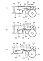
同図において、プロセスカートリッジ30は、感光体ドラム31、帯電ロール32、現像装置33の一部、クリーニング装置34のほかに、クリーニング処理前に感光体ドラム31を除電するデバイスとしてのイレーズランプ35が含まれる感光体カートリッジ30aと、この感光体カートリッジ30aの下方側に前記感光体カートリッジ30aに対して揺動自在で且つ位置決めされた状態で設けられると共に現像装置33の主要部が含まれる現像カートリッジ30bとを備えている。
<Outline of process cartridge>
FIG. 3 shows details of the process cartridge 30 used in the present embodiment.
In the figure, a process cartridge 30 includes a photosensitive drum 31, a charging roll 32, a part of a developing device 33, a cleaning device 34, and an erase lamp 35 as a device for discharging the photosensitive drum 31 before the cleaning process. A photosensitive cartridge 30a included, and a developing cartridge 30b provided below the photosensitive cartridge 30a so as to be swingable and positioned with respect to the photosensitive cartridge 30a and including a main part of the developing device 33. And.

特に、本実施の形態では、現像装置33は、感光体ドラム31に対向し且つ感光体ドラム31上の静電潜像をトナー及びキャリアからなる現像剤Gにて可視像化する現像ユニット100と、この現像ユニット100に対してトナーTを補給するトナー補給ユニット110,120(本実施の形態では、メイントナー補給ユニット110、サブトナー補給ユニット120との分離型を採用)とを備えている。
そして、感光体カートリッジ30aはクリーニング装置34をユニット化したクリーニングユニット200とサブトナー補給ユニット120とを横方向に一体化した構成になっており、また、現像カートリッジ30bは現像ユニット100とメイントナー補給ユニット110とを横方向に一体化した構成になっている。
In particular, in the present embodiment, the developing device 33 faces the photosensitive drum 31 and visualizes the electrostatic latent image on the photosensitive drum 31 with a developer G composed of toner and carrier. And toner replenishing units 110 and 120 for replenishing toner T to the developing unit 100 (in this embodiment, a separate type from the main toner replenishing unit 110 and the sub toner replenishing unit 120 is employed).
The photosensitive cartridge 30a has a configuration in which a cleaning unit 200 in which the cleaning device 34 is unitized and a sub-toner replenishment unit 120 are integrated in the horizontal direction, and the development cartridge 30b has a development unit 100 and a main toner replenishment unit. 110 is integrated in the horizontal direction.

更に、本実施の形態では、現像カートリッジ30bは装置筐体21に位置決め固定された感光体カートリッジ30aに対し現像ユニット100部位にピボット軸30cにて揺動自在に設けられており、感光体カートリッジ30aと現像カートリッジ30bとの間には露光装置40からの走査光が通過可能な走査用通路135が確保され、この走査用通路135の入口付近の各パーツカートリッジ30a,30bの両側には弾性部材からなるスペーサ130が介在され、感光体カートリッジ30aに対して現像カートリッジ30bを加圧付勢するようになっている。尚、スペーサ130に代えて、あるいは、加えて付勢スプリング等の付勢要素を用いるようにしてもよいことは勿論である。   Further, in the present embodiment, the developing cartridge 30b is provided at the developing unit 100 portion so as to be swingable by the pivot shaft 30c with respect to the photosensitive cartridge 30a positioned and fixed to the apparatus housing 21, and the photosensitive cartridge 30a. A scanning passage 135 through which scanning light from the exposure device 40 can pass is secured between the developing cartridge 30b and an elastic member on both sides of each part cartridge 30a, 30b near the entrance of the scanning passage 135. A spacer 130 is interposed to pressurize the developing cartridge 30b against the photosensitive cartridge 30a. Of course, a biasing element such as a biasing spring may be used instead of or in addition to the spacer 130.

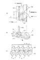
また、本実施の形態では、感光体カートリッジ30aのサブトナー補給ユニット120には、図3及び図4(a)(b)に示すように、感光体ドラム31の軸方向に直交する方向に延びる例えば一対の支持突起141が設けられている。
そして、装置筐体21のカートリッジ受部(図示せず)にプロセスカートリッジ30を装着した時に、感光体ドラム31を回転自在に支承する支持軸の両端が、カートリッジ受部に設けられた図示外の固定受け部材により所定の位置に固定されると共に、該支持軸に回転自在に配設された該感光体ドラム31の片端に配設された駆動伝達部材(例えば駆動伝達ギア)が、カートリッジ受部に設けられた図示外の駆動系に連結係合する。また、前記一対の支持突起141がカートリッジ受部の被係合部(凹部や孔等)に係合し、感光体カートリッジ30aが装置筐体21に位置決め固定されるようになっている。ここで、装置筐体21のカートリッジ受部はプロセスカートリッジ30を収容保持できるものであればよく、筐体フレーム自体を用いて構成してもよいし、筐体フレームに別部材を設けて構成してもよい。
特に、本実施の形態にあっては、前記支持突起141は、感光体ドラム31から離れたユニット外壁に設けられると共に、感光体ドラム31を駆動する駆動力による、該プロセスカートリッジ30の回転を抑える機能も有している。
尚、図4中、符号142はプロセスカートリッジ30を着脱操作する際の把持アームである。
In the present embodiment, the sub-toner replenishment unit 120 of the photoconductor cartridge 30a extends in a direction orthogonal to the axial direction of the photoconductor drum 31, as shown in FIGS. 3 and 4A and 4B, for example. A pair of support protrusions 141 are provided.
Then, when the process cartridge 30 is mounted in a cartridge receiving portion (not shown) of the apparatus housing 21, both ends of the support shaft that rotatably supports the photosensitive drum 31 are not shown in the drawing provided in the cartridge receiving portion. A drive transmission member (for example, a drive transmission gear) disposed at one end of the photosensitive drum 31 that is fixed at a predetermined position by the fixed receiving member and is rotatably disposed on the support shaft is a cartridge receiving portion. It is connected and engaged with a drive system (not shown) provided in The pair of support protrusions 141 are engaged with engaged portions (such as recesses and holes) of the cartridge receiving portion so that the photosensitive cartridge 30 a is positioned and fixed to the apparatus housing 21. Here, the cartridge receiving portion of the apparatus housing 21 may be any as long as it can accommodate and hold the process cartridge 30, and may be configured using the housing frame itself, or may be configured by providing another member on the housing frame. May be.
In particular, in the present embodiment, the support protrusion 141 is provided on the outer wall of the unit away from the photosensitive drum 31 and suppresses the rotation of the process cartridge 30 due to the driving force that drives the photosensitive drum 31. It also has a function.
In FIG. 4, reference numeral 142 denotes a gripping arm used when the process cartridge 30 is attached and detached.

<現像装置>
本実施の形態で用いられる現像装置33を構成する各ユニット100,110,120について説明する。
−現像ユニット−
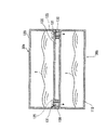
本実施の形態において、現像ユニット100は、図3、図5及び図6に示すように、所謂二成分現像方式を採用したものであって、感光体ドラム31の下方側には感光体ドラム31側に開口する現像ハウジング101を有し、この現像ハウジング101内をトナー及びキャリアからなる現像剤Gが収容可能な現像剤収容室102として構成すると共に、現像ハウジング101の開口に面した部位に現像剤担持用の現像ロール103を配設したものである。そして、この現像ユニット100は、現像ロール103の軸方向に沿って延びる仕切壁106にて現像剤収容室102を二分すると共に、この仕切壁106の長手方向両端に連通口107,108を開設することにより、現像剤収容室102に現像剤循環経路を構成し、この現像剤循環経路には現像ロール103の軸方向に沿って一対の撹拌搬送オーガー104,105を配設し、現像剤循環経路内の現像剤Gを撹拌しながら搬送するようになっている。
ここで、撹拌搬送オーガー104は既存の現像剤Gに専ら補給されたトナーTを撹拌混合することを主眼としたアドミックスオーガーであり、一方、撹拌搬送オーガー105は前記トナーの撹拌混合機能に加えて現像ロール103への現像剤供給機能を担ったサプライオーガーである。
尚、本実施の形態では、現像ロール103寄りの撹拌搬送オーガー105が現像ロール103への現像剤供給機能を兼用しているが、撹拌搬送オーガー105とは別に現像剤供給部材(ロールやパドル等)を付加してもよいことは勿論である。また、現像ロール103の周囲には現像剤層厚を規制するトリミング部材や未使用現像剤を回収する回収部材などが必要に応じて設けられる。
<Developing device>
The units 100, 110, and 120 constituting the developing device 33 used in this embodiment will be described.
-Development unit-
In the present embodiment, the developing unit 100 employs a so-called two-component developing system as shown in FIGS. 3, 5, and 6, and the photosensitive drum 31 is disposed below the photosensitive drum 31. The developing housing 101 is open to the side, and the developing housing 101 is configured as a developer containing chamber 102 in which a developer G composed of toner and carrier can be stored, and development is performed at a portion facing the opening of the developing housing 101. A developing roll 103 for supporting the agent is disposed. The developing unit 100 bisects the developer accommodating chamber 102 with a partition wall 106 extending along the axial direction of the developing roll 103, and opens communication ports 107 and 108 at both longitudinal ends of the partition wall 106. As a result, a developer circulation path is formed in the developer storage chamber 102, and a pair of agitation transport augers 104 and 105 are disposed along the axial direction of the developing roll 103 in this developer circulation path. The developer G inside is conveyed while stirring.
Here, the agitating / conveying auger 104 is an admix auger whose main purpose is to agitate and mix the toner T replenished exclusively to the existing developer G. On the other hand, the agitating / conveying auger 105 is added to the agitating and mixing function of the toner. This is a supply auger responsible for the developer supply function to the developing roll 103.
In this embodiment, the agitating / conveying auger 105 near the developing roll 103 also serves as a developer supplying function to the developing roll 103. However, a developer supplying member (roll, paddle, etc.) is provided separately from the agitating / conveying auger 105. Of course, it may be added. Further, a trimming member for regulating the developer layer thickness, a collecting member for collecting unused developer, and the like are provided around the developing roll 103 as necessary.

−メイントナー補給ユニット−
また、メイントナー補給ユニット110は、図3、図5及び図6に示すように、現像ユニット100の現像ハウジング101の奥側隔壁を一部兼用するメイン補給ハウジング111を有し、このメイン補給ハウジング111内を補給用トナーTが補給可能に収容されるトナー補給室として構成するようになっている。
特に、本実施の形態では、トナー補給室は、補給用トナーTが収容されるトナー収容室112と、このトナー収容室112と連通し且つ現像ユニット100に対してトナーTを定量的に補給するディスペンス室113とに分かれている。ここで、ディスペンス室113は現像ハウジング101の奥側隔壁101aの下部寄りに厚肉部101bを設け、この厚肉部101b内に現像ロール103の軸方向に沿って延びる断面略円形の長尺通路(トンネル状通路)として構成されている。
そして、前記厚肉部101bの長手方向奥側のうちトナー収容室112に面した部位にはディスペンス入口開口114が開設されると共に、厚肉部101bのうち現像剤収容室102に面した部位で前記ディスペンス入口開口114とは長手方向反対側にはトナー供給口115が開設されている。
-Main toner supply unit-
Further, as shown in FIGS. 3, 5 and 6, the main toner replenishment unit 110 has a main replenishment housing 111 which also serves as a part of the rear partition wall of the developing housing 101 of the developing unit 100. 111 is configured as a toner replenishing chamber in which replenishing toner T is accommodated so as to be replenished.
In particular, in the present embodiment, the toner supply chamber communicates with the toner storage chamber 112 in which the supply toner T is stored, and the toner storage chamber 112, and quantitatively supplies the toner T to the developing unit 100. It is divided into a dispensing chamber 113. Here, the dispensing chamber 113 is provided with a thick portion 101b near the lower portion of the rear partition 101a of the developing housing 101, and a long passage having a substantially circular cross section extending along the axial direction of the developing roll 103 in the thick portion 101b. It is configured as a (tunnel-shaped passage).
A dispensing inlet opening 114 is formed in a portion facing the toner storage chamber 112 on the inner side in the longitudinal direction of the thick portion 101b, and a portion facing the developer storage chamber 102 in the thick portion 101b. A toner supply port 115 is opened on the opposite side of the dispensing inlet opening 114 in the longitudinal direction.

更に、トナー収容室112内には補給用トナーTを撹拌搬送するためのアジテータ116と、このアジテータ116にて撹拌搬送されたトナーTをディスペンス室113のディスペンス入口開口114に向けて撹拌搬送するアジテータ117とが配設されている。
ここで、図5に示すように、アジテータ116はクランク状の回転ロッド401の先端にPETフィルム等からなるアジテートフィルム402を有し、このアジテートフィルム402にてトナーをトナー補給室壁面に沿って搬送するものである。そして、回転ロッド401のアジテータフィルム402の反対側には回転ロッド401の径方向に延びる適宜数の撹拌ロッド403が設けられ、トナー補給室内のトナーを撹拌するようになっている。また、アジテータ117はアジテータ116と略同様に構成して差し支えないが、例えばアジテートフィルムに適宜切り込みを設けるなどしてディスペンス入口開口114に向けてトナー搬送方向を調整するようにすることが好ましい。但し、アジテータ116,117としては撹拌搬送コイルスプリングなどを用いるようにしてもよいことは勿論である。
尚、図6においては、アジテータ116,117の形態は模式的に示されている。
一方、ディスペンス室113には長手方向に沿ってディスペンスオーガー118が配設されている。特に、本実施の形態では、ディスペンスオーガー118は現像ユニット100内の撹拌搬送オーガー104,105と略同径かそれ以下の螺旋羽根を備えたものになっていり、更に、ディスペンスオーガー118のピッチが撹拌搬送オーガー104,405のピッチ以下に設定されている。
Further, an agitator 116 for agitating and conveying the replenishing toner T in the toner storage chamber 112, and an agitator for agitating and conveying the toner T agitated and conveyed by the agitator 116 toward the dispensing inlet opening 114 of the dispensing chamber 113. 117 is disposed.
Here, as shown in FIG. 5, the agitator 116 has an agitate film 402 made of a PET film or the like at the tip of a crank-shaped rotating rod 401, and the toner is transported along the wall of the toner supply chamber by the agitate film 402. To do. An appropriate number of stirring rods 403 extending in the radial direction of the rotating rod 401 are provided on the opposite side of the rotating rod 401 from the agitator film 402 so as to stir the toner in the toner supply chamber. The agitator 117 may be configured in substantially the same manner as the agitator 116, but it is preferable to adjust the toner conveyance direction toward the dispense inlet opening 114 by, for example, appropriately cutting the agitate film. However, as agitator 116, 117, it is needless to say that a stirring and conveying coil spring or the like may be used.
In FIG. 6, the forms of the agitators 116 and 117 are schematically shown.
On the other hand, a dispense auger 118 is disposed in the dispense chamber 113 along the longitudinal direction. In particular, in the present embodiment, the dispense auger 118 is provided with a spiral blade having a diameter substantially equal to or less than that of the agitating / conveying augers 104 and 105 in the developing unit 100, and the pitch of the dispense auger 118 is further reduced. The pitch is set to be equal to or less than the pitch of the agitation transport augers 104 and 405.

また、本実施の形態では、トナー供給口115は、図7(a)(b)に示すように、その下端が現像剤収容室102に収容される現像剤Gの表面位置より下方に位置するように開口している。すなわち、トナー供給口115は現像剤収容室102の現像剤Gの表面位置から少なくとも埋もれていればよく、現像剤収容室102の現像剤堆積部に補給用トナーTを横から供給可能とし、補給用トナーTの現像剤への撹拌混合性を確保するようになっている。
特に、本実施の形態では、トナー供給口115は、図7(a)(b)に示すように、補給用トナーTを現像剤収容室102へ供給すると共に補給用トナー供給方向(矢印α方向)と逆行する方向(矢印β方向)に現像剤収容室102の現像剤Gの一部を逆流させるようになっている。
In the present embodiment, as shown in FIGS. 7A and 7B, the lower end of the toner supply port 115 is located below the surface position of the developer G stored in the developer storage chamber 102. So that it is open. That is, the toner supply port 115 only needs to be buried at least from the surface position of the developer G in the developer storage chamber 102, and the replenishment toner T can be supplied from the side to the developer accumulation portion of the developer storage chamber 102. The mixing and mixing properties of the toner T for the developer to the developer are ensured.
In particular, in the present embodiment, the toner supply port 115 supplies the replenishment toner T to the developer storage chamber 102 and also supplies the replenishment toner (in the direction of arrow α), as shown in FIGS. ) In a direction (arrow β direction) opposite to that of the developer G in the developer storage chamber 102.

具体的には、ディスペンス室113内のトナー供給口115に面した部位でのトナー搬送方向と、現像剤収容室102のうちトナー供給口115に面した部位での現像剤搬送方向とが逆行しており、補給用トナーTと現像剤Gとの界面にて剪断力が生ぜしめられ、トナーT、現像剤Gに対しα、βで示すような循環流が生成するようになっている。また、ディスペンスオーガー118は通常の撹拌搬送用のオーガー羽根118aのほかに、トナー供給口115に面した部位にせき止め用のオーガー羽根118bを有しており、このせき止め用のオーガー羽根118bによりせき止められた領域にてトナーTは一時的に滞留させられるため、このトナー滞留域がトナーTと現像剤Gとを予備混合する予備混合領域PMとして働くようになっている。   Specifically, the toner transport direction at the portion facing the toner supply port 115 in the dispense chamber 113 and the developer transport direction at the portion facing the toner supply port 115 in the developer storage chamber 102 are reversed. In addition, a shearing force is generated at the interface between the replenishing toner T and the developer G, and a circulating flow as indicated by α and β is generated with respect to the toner T and the developer G. The dispensing auger 118 has a damming auger blade 118b at a portion facing the toner supply port 115 in addition to a normal agitating and conveying auger blade 118a. Since the toner T is temporarily retained in this area, the toner retention area functions as a premix area PM for premixing the toner T and the developer G.

つまり、撹拌搬送オーガー(アドミックスオーガー)104で搬送される現像剤Gの一部は、トナー供給口115からディスペンスオーガー118が配置されたトンネル状のディスペンス室113に入り込み、ディスペンスオーガー118の通常のオーガー羽根118aの回転により現像剤移動方向とは逆方向にトナーと一緒に搬送され、トナー滞留域(予備混合領域PM)に至る。
このとき、補給用トナーTの周りには流れ込んだ現像剤があたかも黄粉もちの黄粉のようにまとわりつき、トナー滞留域を経て、せき止め用のオーガー羽根118bにて再びトナー供給口115から現像剤収容室102へと押し出される。
この押し出し時には、補給用トナーTの周りには上述したように現像剤Gが黄粉の如くまぶされているので、トナー単独の場合に比べて重くなっている。従って、トナー供給口115から補給された補給用トナーTは、アドミックスオーガー104で搬送される現像剤Gの流れの中で、その表面に浮き上がってくることが困難になり、補給用トナーTの撹拌混合性が向上する。
That is, a part of the developer G transported by the stirring transport auger (admix auger) 104 enters the tunnel-like dispense chamber 113 in which the dispense auger 118 is disposed from the toner supply port 115, The rotation of the auger blade 118a conveys the toner together with the toner in the direction opposite to the developer moving direction, and reaches the toner retention area (preliminary mixing area PM).
At this time, the developer that has flowed around the replenishing toner T clumps as if it is yellowish powdery yellow powder, passes through the toner retention area, and again from the toner supply port 115 through the toner supply port 115 by the auger blade 118b for preventing clogging. It is pushed out to 102.
At the time of the extrusion, the developer G is coated like yellow powder around the replenishment toner T as described above, so that it is heavier than the case of the toner alone. Accordingly, it becomes difficult for the replenishing toner T replenished from the toner supply port 115 to float on the surface of the developer G conveyed by the admix auger 104. Stir and mixability is improved.

また、このような現像剤の一部逆流現象が生ずる態様にあっては、ディスペンス室113内の補給用トナーTがトナー供給口115から押し出される押圧分布は現像剤収容室102の現像剤Gによる内圧に比べて大きい部位と小さい部位とが混在し、補給用トナーTの押圧が現像剤収容室102の現像剤Gの内圧より大きい部位から補給用トナーTが現像剤収容室102側に供給され、逆に、小さい部位からは現像剤Gがディスペンス室113に入り込むものと推測される。
従って、ディスペンスオーガー118やアドミックスオーガー104などの搬送量や搬送速度、オーガー径、オーガーピッチなどは現像剤Gの一部逆流現象が可能なように適宜選定されるものである。
Further, in such a mode in which a partial backflow phenomenon of the developer occurs, the pressure distribution in which the replenishment toner T in the dispense chamber 113 is pushed out from the toner supply port 115 is caused by the developer G in the developer storage chamber 102. A portion that is larger and smaller than the internal pressure is mixed, and the replenishment toner T is supplied to the developer storage chamber 102 from a portion where the pressure of the replenishment toner T is greater than the internal pressure of the developer G in the developer storage chamber 102. On the contrary, it is estimated that the developer G enters the dispensing chamber 113 from a small portion.
Accordingly, the transport amount, transport speed, auger diameter, auger pitch, and the like of the dispense auger 118 and the admix auger 104 are appropriately selected so that a partial backflow phenomenon of the developer G is possible.

また、本実施の形態では、トナー供給口115は、現像剤収容室102の端部位置から離れた位置に開口しているため、現像剤収容室102からの現像剤逆流量が過大になる事態を有効に抑えることができる。
更に、トナー供給口115の下端がアドミックスオーガー104の回転中心より下方に設定されていれば、アドミックスオーガー104の回転中心より下方からトナーTが補給されるので、補給されたトナーTがアドミックスオーガー104に巻き込まれ、速やかに現像剤と撹拌混合される。
また、ディスペンスオーガー118の中心はアドミックスオーガー104の回転中心よりも略同じか下方に位置するように設定されているため、アドミックスオーガー104の回転中心より下方からトナーが補給されることになり、その分、補給されたトナーがアドミックスオーガー104に巻き込まれ、速やかに撹拌混合される。
Further, in the present embodiment, the toner supply port 115 is opened at a position away from the end position of the developer accommodating chamber 102, so that the developer reverse flow rate from the developer accommodating chamber 102 becomes excessive. Can be effectively suppressed.
Furthermore, if the lower end of the toner supply port 115 is set below the rotation center of the admix auger 104, the toner T is replenished from below the rotation center of the admix auger 104. It is caught in the mix auger 104 and quickly stirred and mixed with the developer.
Further, since the center of the dispense auger 118 is set to be substantially the same as or below the rotation center of the admix auger 104, toner is supplied from below the rotation center of the admix auger 104. Accordingly, the replenished toner is taken up in the admix auger 104 and quickly stirred and mixed.

更にまた、ディスペンス入口開口114については適宜開設して差し支えないが、ディスペンス室113内でのトナー内圧を充分に上げるという観点からすれば、ディスペンス入口開口114はディスペンスオーガ118のピッチよりも大きい方が好ましい。また、ディスペンス室113の補給用トナーTの搬送長がディスペンス入口開口114よりも充分に長い方が良い。
また、トナー収容室112の容量については、ディスペンス室113の容量、あるいは、ディスペンス室113と現像剤収容室102との合計容量よりもトナー収容室112の容量を大きくすれば、トナー供給口115からのトナーを継続的に安定補給することができる。
更に、本実施の形態では、アジテータ116,117の回転中心はディスペンスオーガー118及び撹拌搬送オーガー104,105よりも上方に位置するように配置されている。
このため、トナー収容室112からディスペンス室113、現像剤収容室102までトナーTを持ち上げる必要がないため、ディスペンス室113でのトナー内圧を効果的に上げることができ、ディスペンス室113でのトナー内圧を損なうことなく、現像剤収容室102へのトナー補給をスムースに行うことができる。
Furthermore, the dispense inlet opening 114 may be appropriately opened, but from the viewpoint of sufficiently increasing the toner internal pressure in the dispense chamber 113, the dispense inlet opening 114 should be larger than the pitch of the dispense auger 118. preferable. Further, it is preferable that the transport length of the replenishment toner T in the dispense chamber 113 is sufficiently longer than the dispense inlet opening 114.
Further, regarding the capacity of the toner storage chamber 112, if the capacity of the toner storage chamber 112 is made larger than the capacity of the dispense chamber 113 or the total capacity of the dispense chamber 113 and the developer storage chamber 102, the toner supply port 115 can be used. The toner can be continuously and stably supplied.
Furthermore, in the present embodiment, the rotational centers of the agitators 116 and 117 are arranged so as to be positioned above the dispense auger 118 and the stirring and conveying augers 104 and 105.
Therefore, there is no need to lift the toner T from the toner storage chamber 112 to the dispensing chamber 113 and the developer storage chamber 102, so that the toner internal pressure in the dispense chamber 113 can be effectively increased, and the toner internal pressure in the dispense chamber 113 can be increased. The toner can be smoothly supplied to the developer storage chamber 102 without impairing the toner.

−サブトナー補給ユニット−
また、本実施の形態において、サブトナー補給ユニット120は、図3に示すように、クリーニングユニット200の背面側に隣接するサブ補給ハウジング121を有し、このサブ補給ハウジング121内を補給用トナーTが補給可能に収容されるトナー補給室122として構成するようになっている。
そして、トナー補給室122内には補給用トナーTを撹拌搬送するための一対のアジテータ123,124が配設されている。
ここで、サブトナー補給ユニット120とメイントナー補給ユニット110との連通構造としては、図3及び図8に示すように、弾性部材からなるスペーサ130に連通路(トナー供給路)131を形成したものが用いられる。本実施の形態では、スペーサ130は各ユニット110,120間の両側二箇所に設けられ、夫々にトナー供給路131を形成しているが、例えばいずれか一方のスペーサ130にのみトナー供給路131を形成してもよいし、あるいは、片側一箇所にスペーサ130を設け、このスペーサ130にトナー供給路131を形成しても差し支えない。
尚、本実施の形態では、このサブトナー補給ユニット120は、図8に仮想線で示すように、未使用時にはトナー供給路131との連結部位を使用時に開放可能なシール部材125で塞ぐことが好ましい。この場合、プロセスカートリッジ30未使用時(例えば輸送時)にサブトナー補給ユニット120内のトナーがトナー供給路131に入り込み、目詰まりを起こす懸念がないばかりか、サブトナー補給ユニット120内のトナーがメイントナー補給ユニット110側に偏って充填され、メイントナー補給ユニット110内のトナーの充填密度が不必要に高くなってしまう事態を有効に回避することができる。
-Sub-toner supply unit-
Further, in the present embodiment, the sub-toner replenishment unit 120 has a sub-replenishment housing 121 adjacent to the back side of the cleaning unit 200, as shown in FIG. It is configured as a toner replenishing chamber 122 that is accommodated so as to be replenished.
In the toner supply chamber 122, a pair of agitators 123 and 124 for stirring and transporting the supply toner T are disposed.
Here, as a communication structure between the sub-toner supply unit 120 and the main toner supply unit 110, as shown in FIGS. 3 and 8, a spacer 130 made of an elastic member is formed with a communication path (toner supply path) 131. Used. In the present embodiment, the spacers 130 are provided at two positions on both sides between the units 110 and 120, and the toner supply paths 131 are formed respectively. For example, the toner supply paths 131 are provided only in one of the spacers 130. Alternatively, the spacer 130 may be provided at one location on one side, and the toner supply path 131 may be formed in the spacer 130.
In the present embodiment, as shown in phantom lines in FIG. 8, the sub toner replenishment unit 120 preferably closes the connecting portion with the toner supply path 131 with a seal member 125 that can be opened when in use. . In this case, when the process cartridge 30 is not used (for example, during transportation), the toner in the sub toner replenishment unit 120 enters the toner supply path 131 and there is no fear of clogging, and the toner in the sub toner replenishment unit 120 is the main toner. It is possible to effectively avoid a situation in which the toner filling density in the main toner replenishing unit 110 is unnecessarily increased because the toner is charged in the replenishment unit 110 side.

そして、本実施の形態では、メイントナー補給ユニット110から現像ユニット100に所定量のトナーTが補給されると、これと同時に、サブトナー補給ユニット120内のトナーTがメイントナー補給ユニット110に補充されるようになっている。このため、メイントナー補充ユニット110内にはサブトナー補給ユニット120が空になるまで略一定のトナーTが充填されることになり、現像カートリッジ30bの重量変化は少なく抑えられる。
このとき、感光体カートリッジ30aは装置筐体21のカートリッジ受部に対して位置決め固定されているため、サブトナー補給ユニット120のトナー収容量変化は現像カートリッジ30bの重量変化には何等影響しない。
よって、サブトナー補給ユニット120が空に至るまでは感光体カートリッジ30aに対する現像カートリッジ30bの加圧付勢力の変動は抑えられ、その分、画像乱れを有効に防止することが可能である。
In this embodiment, when a predetermined amount of toner T is supplied from the main toner supply unit 110 to the developing unit 100, the toner T in the sub toner supply unit 120 is supplied to the main toner supply unit 110 at the same time. It has become so. For this reason, the main toner replenishment unit 110 is filled with the substantially constant toner T until the sub toner replenishment unit 120 becomes empty, and the change in the weight of the developing cartridge 30b is suppressed to a small extent.
At this time, since the photosensitive cartridge 30a is positioned and fixed with respect to the cartridge receiving portion of the apparatus housing 21, the change in the toner storage amount of the sub toner replenishment unit 120 does not affect the change in the weight of the developing cartridge 30b.
Therefore, fluctuations in the pressing and urging force of the developing cartridge 30b with respect to the photosensitive cartridge 30a are suppressed until the sub-toner replenishing unit 120 is empty, and image disturbance can be effectively prevented correspondingly.

更に、感光体カートリッジ30aが装置筐体21に位置決め固定されていることから、少なくとも走査用通路135を形成する感光体カートリッジ30aの下側面位置が変化することはなく、その分、感光体カートリッジ30aに揺動支持されている現像カートリッジ30bの位置が変動したとしても、走査用通路135が遮られる虞れは少ない。   Further, since the photosensitive member cartridge 30a is positioned and fixed to the apparatus housing 21, at least the lower surface position of the photosensitive member cartridge 30a forming the scanning passage 135 does not change, and accordingly, the photosensitive member cartridge 30a. Even if the position of the developing cartridge 30b that is pivotally supported is changed, there is little possibility that the scanning passage 135 is blocked.

<クリーニング装置>
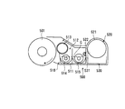
また、本実施の形態において、クリーニング装置34は、図9に示すように、感光体カートリッジ30aにクリーニングユニット200として組み込まれている。
このクリーニングユニット200は感光体ドラム31に対向して開口するクリーニングハウジング201を有し、このクリーニングハウジング201内を廃トナーが収容可能な廃トナー収容室203として構成すると共に、クリーニングハウジング201の上壁201aを感光体ドラム31側に向けて庇状に延ばしたものである。
そして、このクリーニングハウジング201の開口下縁部201bにはクリーニングブレード210が配設されており、このクリーニングブレード210はクリーニングハウジング201の開口下縁部201b及び上壁201a両側から垂下した側壁部(図示せず)に略L字状のブレードホルダ212を取付け、このブレードホルダ212の先端部外側にウレタンゴム等の弾性体からなるブレード本体211を取付け、このブレード本体211の先端を感光体ドラム31の回転方向(図9では反時計回り方向)に対向するように弾接させたものである。
一方、クリーニングハウジング201の開口上縁部(本実施の形態では上壁201a先端近傍)にはPET、ポリウレタンなどのフィルムシール215が設けられ、このフィルムシール215の先端部が感光体ドラム31の回転方向に沿って弾接し、クリーニングブレード210によって回収された廃トナーの飛散を防止するようになっている。
<Cleaning device>
In the present embodiment, the cleaning device 34 is incorporated as a cleaning unit 200 in the photosensitive member cartridge 30a as shown in FIG.
The cleaning unit 200 includes a cleaning housing 201 that opens to face the photosensitive drum 31. The cleaning housing 201 is configured as a waste toner storage chamber 203 that can store waste toner, and an upper wall of the cleaning housing 201. 201a is extended in a bowl shape toward the photosensitive drum 31 side.
A cleaning blade 210 is disposed on the lower opening edge 201b of the cleaning housing 201. The cleaning blade 210 is a side wall (see FIG. 5) that hangs down from both the opening lower edge 201b and the upper wall 201a of the cleaning housing 201. (Not shown), a substantially L-shaped blade holder 212 is attached, and a blade body 211 made of an elastic material such as urethane rubber is attached to the outside of the distal end portion of the blade holder 212, and the distal end of the blade body 211 is attached to the photosensitive drum 31. It is elastically contacted so as to face the rotation direction (counterclockwise direction in FIG. 9).
On the other hand, a film seal 215 such as PET or polyurethane is provided at the upper edge of the opening of the cleaning housing 201 (in the present embodiment, in the vicinity of the front end of the upper wall 201a), and the front end of the film seal 215 is the rotation of the photosensitive drum 31. Elastic contact is made along the direction to prevent the waste toner collected by the cleaning blade 210 from scattering.

本実施の形態において、クリーニングブレード210のクリーニングハウジング201への取付部以外の部分はクリーニングハウジング201の上壁201aの庇状部分と略平行に配置されており、クリーニングブレード210で掻き取った廃トナーを一時的に溜める廃トナー溜まり部213(本例ではブレードホルダ212内面が相当)として構成される。特に、本例では、廃トナー溜まり部213は廃トナー収容室203に向かって下り勾配になっており、廃トナーTdの搬送性を向上させることが可能である。
尚、本実施の形態では、廃トナー溜まり部213はクリーニングブレード210のみで構成されているが、クリーニングブレード210のみならずクリーニングハウジング201の一部をも用いて構成するようにしてもよい。
また、このクリーニングハウジング201とクリーニングブレード210との間には感光体ドラム31に対して凹所となるスペースが確保されるため、この凹所を利用して帯電ロール32が配設されている。
尚、クリーニングハウジング201の上壁201aの先端にはイレーズランプ35の保持ブロック202が設けられている。
In the present embodiment, the portion other than the attachment portion of the cleaning blade 210 to the cleaning housing 201 is disposed substantially parallel to the bowl-shaped portion of the upper wall 201a of the cleaning housing 201, and the waste toner scraped off by the cleaning blade 210 is used. Is configured as a waste toner reservoir portion 213 (corresponding to the inner surface of the blade holder 212 in this example). In particular, in this example, the waste toner reservoir 213 has a downward slope toward the waste toner storage chamber 203, so that the transportability of the waste toner Td can be improved.
In the present embodiment, the waste toner reservoir 213 is configured by only the cleaning blade 210, but may be configured by using not only the cleaning blade 210 but also a part of the cleaning housing 201.
Further, since a space that becomes a recess with respect to the photosensitive drum 31 is secured between the cleaning housing 201 and the cleaning blade 210, the charging roll 32 is disposed using the recess.
A holding block 202 for the erase lamp 35 is provided at the tip of the upper wall 201a of the cleaning housing 201.

更に、本実施の形態において、クリーニングハウジング201内には、クリーニングブレード210で掻き取った廃トナーTdを廃トナー収容室203側に搬送する廃トナー搬送部材220が設けられている。
この廃トナー搬送部材220は、廃トナー収容室203から廃トナー溜まり部213との間に跨る部材要素としての搬送プレート221を有し、この搬送プレート221の廃トナー収容室203側端部には外部からの駆動力が入力可能な駆動入力部222を設けると共に、搬送プレート221の感光体ドラム31側端部には廃トナー溜まり部213と接触可能な突出部223を設けたものである。
ここで、搬送プレート221は板状のままでも差し支えないが、軽量化及び上面部への廃トナーTdの堆積などを有効に回避するという観点からすれば、搬送プレート221の突出部223及び駆動入力部222以外の部位に開口224を形成することが好ましい。また、突出部223の形成箇所については搬送プレート221の端部である必要は必ずしもなく、端部から離れた部位でもよいし、また、突出部223の数についても少なくとも一つあればよいが、複数設けても差し支えない。更に、突出部223の形成法については、搬送プレート221の先端部を折り曲げて形成したり、あるいは、搬送プレート221の一部に突出部223を一体的若しくは別体にて形成する等適宜選定して差し支えない。
尚、廃トナー搬送部材220の部材要素としては、必ずしも搬送プレート221である必要はなく、例えば枠フレーム構造のものなどを用いてもよいことは勿論である。
Further, in the present embodiment, a waste toner transport member 220 that transports the waste toner Td scraped by the cleaning blade 210 to the waste toner storage chamber 203 side is provided in the cleaning housing 201.
The waste toner transport member 220 has a transport plate 221 as a member element straddling between the waste toner storage chamber 203 and the waste toner reservoir 213, and is disposed at the end of the transport plate 221 on the side of the waste toner storage chamber 203. A drive input unit 222 capable of inputting an external driving force is provided, and a protrusion 223 capable of contacting the waste toner reservoir 213 is provided at the end of the transport plate 221 on the photosensitive drum 31 side.
Here, the transport plate 221 may remain plate-shaped, but from the viewpoint of reducing the weight and effectively avoiding the accumulation of the waste toner Td on the upper surface portion, the protruding portion 223 of the transport plate 221 and the drive input. It is preferable to form the opening 224 in a portion other than the portion 222. In addition, the projecting portion 223 is not necessarily formed at the end portion of the transport plate 221, and may be a portion away from the end portion, and the number of the projecting portions 223 may be at least one. There may be more than one. Further, the method for forming the protruding portion 223 is appropriately selected, for example, by bending the tip portion of the transport plate 221 or by forming the protruding portion 223 integrally or separately on a part of the transport plate 221. It does not matter.
Of course, the member element of the waste toner conveying member 220 is not necessarily the conveying plate 221, and it is of course possible to use a frame frame structure, for example.

そして、本実施の形態では、例えば図9に示すように、廃トナー搬送部材220の駆動入力部222には回転軌跡状の駆動力が入力されるようになっており、この回転軌跡状の駆動力は例えば回転駆動機構230の一種であるクランク軸231を回転中心を中心として回転駆動させることにより容易に得られるものである。
更に、本実施の形態では、廃トナー搬送部材220には廃トナー搬送部材220の移動姿勢を規制するための姿勢規制機構240が付設されている。
本実施の形態において、姿勢規制機構240は、廃トナー搬送部材220の突出部223側に一端が係合し且つ他端がクリーニングハウジング201の一部に係合する付勢スプリング241にて構成され、駆動入力部222から離間する方向に向かって廃トナー搬送部材220を付勢するものである。
In this embodiment, for example, as shown in FIG. 9, a driving force in the form of a rotation locus is input to the drive input unit 222 of the waste toner conveying member 220. The force can be easily obtained, for example, by rotating a crankshaft 231 that is a kind of the rotation drive mechanism 230 around the rotation center.
Further, in the present embodiment, the waste toner conveying member 220 is provided with a posture regulating mechanism 240 for regulating the movement posture of the waste toner conveying member 220.
In the present embodiment, the attitude regulating mechanism 240 is configured by a biasing spring 241 that has one end engaged with the protruding portion 223 side of the waste toner conveying member 220 and the other end engaged with a part of the cleaning housing 201. The waste toner conveying member 220 is biased in a direction away from the drive input unit 222.

特に、本実施の形態では、付勢スプリング241は廃トナー搬送部材220の進退方向に対して斜め方向に向かって配設されている。
ここで、付勢スプリング241の取付構造としては、図9及び図10において、付勢スプリング241の両端に係止フック242,243を設け、クリーニングハウジング201側の係合突起204に一方の係止フック242を係合させ、廃トナー搬送部材220の突出部223側端部に設けられた係合片225に他方の係止フック243を係合させるものが用いられる。
尚、本実施の形態では、付勢スプリング241の取付構造として、クリーニングハウジング201内に係合突起204を設けているが、これに限られるものではなく、例えばクリーニングハウジング201に対し外部に連通する係止孔を開設するような態様にあっては、廃トナー漏れの虞れがあるが、このような場合には、係止孔をシール部材にてシールするようにすればよい。このシール部材としては、CRUに貼られるラベル等を兼用することが好ましい。
In particular, in the present embodiment, the urging spring 241 is disposed in an oblique direction with respect to the advancing / retreating direction of the waste toner conveying member 220.
Here, as a mounting structure of the urging spring 241, in FIGS. 9 and 10, locking hooks 242 and 243 are provided at both ends of the urging spring 241, and one of the locking protrusions 204 on the cleaning housing 201 side is locked. The hook 242 is engaged, and the other hook 243 is engaged with the engagement piece 225 provided at the end of the waste toner conveying member 220 on the protruding portion 223 side.
In this embodiment, the engagement protrusion 204 is provided in the cleaning housing 201 as a mounting structure of the urging spring 241. However, the present invention is not limited to this, and for example, communicates with the cleaning housing 201 to the outside. In a mode in which the locking hole is opened, there is a risk of waste toner leakage. In such a case, the locking hole may be sealed with a seal member. As this sealing member, it is preferable to also use a label or the like attached to the CRU.

このように、廃トナー搬送部材220に付勢スプリング241を付設すると、図9及び図10に示すように、廃トナー搬送部材220の駆動入力部222に回転軌跡状の駆動力が入力されると、これに追従して、廃トナー搬送部材220の突出部223は廃トナー溜まり部213に沿って進退移動する。
このとき、付勢スプリング241は、廃トナー搬送部材220の駆動入力部222の位置変化に対する廃トナー搬送部材220の姿勢変化範囲を規制するようになっている。本例では、廃トナー搬送部材220は、後退移動時には突出部223が廃トナー溜まり部213に沿って廃トナーに対し接触移動し、進出移動時には突出部223が廃トナー溜まり部213上の廃トナーに対し非接触移動するものである。具体的挙動については後述する。
特に、本実施の形態では、付勢スプリング241は廃トナー搬送部材220の進退方向に対して斜め方向に配設されているため、配設スペースの省スペース化を図ることができるほか、廃トナー搬送部材220の移動量に対して付勢スプリング241の伸縮量を小さく設定することが可能になり、その分、廃トナー搬送部材への駆動力負荷変動を緩和することができる点で好ましい。
As described above, when the urging spring 241 is attached to the waste toner conveying member 220, as shown in FIGS. 9 and 10, when a rotational locus-like driving force is input to the drive input portion 222 of the waste toner conveying member 220, as shown in FIGS. Following this, the protrusion 223 of the waste toner conveying member 220 moves forward and backward along the waste toner reservoir 213.
At this time, the biasing spring 241 regulates the posture change range of the waste toner transport member 220 with respect to the change in the position of the drive input unit 222 of the waste toner transport member 220. In this example, when the waste toner transport member 220 moves backward, the protrusion 223 moves in contact with the waste toner along the waste toner reservoir 213, and when the advance toner moves, the protrusion 223 moves to the waste toner reservoir 213. It moves non-contactingly. Specific behavior will be described later.
In particular, in the present embodiment, the urging spring 241 is disposed obliquely with respect to the advancing / retreating direction of the waste toner conveying member 220, so that it is possible to save the space for disposing the waste toner. The amount of expansion / contraction of the urging spring 241 can be set small with respect to the amount of movement of the conveying member 220, which is preferable in that the fluctuation of the driving force applied to the waste toner conveying member can be reduced accordingly.

次に、本実施の形態で用いられるクリーニング装置34の作動について説明する。
今、図9及び図11(a)に示すように、感光体ドラム31上の残留トナーがクリーニングブレード210で掻き取られると、掻き取られた廃トナーTdはクリーニングブレード210上及びその近傍に堆積するが、掻き取られたトナーによって次々に押し出された後、廃トナー溜まり部213(本例ではブレードホルダ211内面が相当)上に廃トナーTdが堆積する。
このような状態において、今、廃トナー搬送部材220の駆動入力部222が図11(a)の位置にあるとすると、廃トナー搬送部材220は最進出位置に配設されることになる。
このとき、付勢スプリング241は廃トナー搬送部材220を駆動入力部222から離間する方向に付勢することになるが、廃トナー搬送部材220の駆動入力部222位置と付勢スプリング241のクリーニングハウジング201側の係止点位置との関係を調整することにより、付勢スプリング241の付勢力成分の一部が廃トナー搬送部材220の突出部223を廃トナー溜まり部213上の廃トナーに接触させる方向に作用するようにしておけば、廃トナー搬送部材220の突出部223は廃トナー溜まり部213上の廃トナーに接触する。
Next, the operation of the cleaning device 34 used in the present embodiment will be described.
As shown in FIGS. 9 and 11A, when the residual toner on the photosensitive drum 31 is scraped off by the cleaning blade 210, the scraped waste toner Td is accumulated on the cleaning blade 210 and in the vicinity thereof. However, after being pushed out one after another by the scraped toner, the waste toner Td accumulates on the waste toner reservoir 213 (in this example, the inner surface of the blade holder 211 corresponds).
In such a state, if the drive input unit 222 of the waste toner transport member 220 is now in the position of FIG. 11A, the waste toner transport member 220 is disposed at the most advanced position.
At this time, the urging spring 241 urges the waste toner conveying member 220 in a direction away from the drive input unit 222, but the position of the driving input unit 222 of the waste toner conveying member 220 and the cleaning housing of the urging spring 241. By adjusting the relationship with the locking point position on the 201 side, a part of the urging force component of the urging spring 241 causes the protrusion 223 of the waste toner conveying member 220 to contact the waste toner on the waste toner reservoir 213. If acting in the direction, the protruding portion 223 of the waste toner conveying member 220 contacts the waste toner on the waste toner reservoir 213.

この状態から回転駆動機構230により駆動入力部222位置が下方へ回転することにより、図11(b)に示すように、廃トナー搬送部材220は次第に傾斜しながら後退移動するが、このとき、廃トナー搬送部材220の突出部223は廃トナー溜まり部213上の廃トナーを廃トナー収容室203側へ向けて搬送していく。
そして、廃トナー搬送部材220の駆動入力部222が最下点に達すると、廃トナー搬送部材220の姿勢は最も急傾斜状態になるが、廃トナー搬送部材220の突出部223と廃トナー溜まり部213との間の接触状態を保つという観点から、廃トナー搬送部材220のうち突出部223以外の部位が廃トナー溜まり部213と非接触にしておくことが効率的である。
この後、廃トナー搬送部材220の駆動入力部222が図11(c)の位置まで回転すると、廃トナー搬送部材220は次第に傾斜姿勢をゆるめながら更に後退移動する。このとき、付勢スプリング241は依然として廃トナー搬送部材220を廃トナー溜まり部213側に押し付けるように作用するため、廃トナー搬送部材220の突出部223は廃トナー溜まり部213に沿って廃トナーTdに対し接触移動し、廃トナーTdを廃トナー収容室203側に移動させる。
尚、本実施の形態では、図11(c)及び図12(a)に示すように、廃トナー搬送部材220が最後退位置に到達したとしても、廃トナー搬送部材220の突出部223は廃トナー溜まり部213の廃トナー収容室203寄り端部までは移動しないが、廃トナー溜まり部213の廃トナー収容室203寄り端部付近まで搬送された廃トナーは、後から搬送されてくる廃トナーによって押され、順次廃トナー収容室203へと収容されていく。
When the position of the drive input portion 222 is rotated downward by the rotation drive mechanism 230 from this state, as shown in FIG. 11B, the waste toner conveying member 220 moves backward while being gradually inclined. The protruding portion 223 of the toner conveying member 220 conveys the waste toner on the waste toner reservoir 213 toward the waste toner storage chamber 203 side.
When the drive input unit 222 of the waste toner conveying member 220 reaches the lowest point, the posture of the waste toner conveying member 220 becomes the steepest inclination, but the protruding portion 223 of the waste toner conveying member 220 and the waste toner reservoir portion. From the standpoint of maintaining the contact state with 213, it is efficient to keep the portion other than the protruding portion 223 of the waste toner conveying member 220 out of contact with the waste toner reservoir 213.
Thereafter, when the drive input unit 222 of the waste toner conveying member 220 is rotated to the position shown in FIG. 11C, the waste toner conveying member 220 is further moved backward while gradually relaxing the inclined posture. At this time, the urging spring 241 still acts to press the waste toner conveying member 220 toward the waste toner reservoir 213, so that the protruding portion 223 of the waste toner conveyance member 220 is disposed along the waste toner reservoir 213 with the waste toner Td. To move the waste toner Td to the waste toner storage chamber 203 side.
In this embodiment, as shown in FIGS. 11C and 12A, even if the waste toner conveying member 220 reaches the last retracted position, the protruding portion 223 of the waste toner conveying member 220 is discarded. Although the waste toner does not move to the end of the toner reservoir 213 closer to the waste toner storage chamber 203, the waste toner transported to the vicinity of the end of the waste toner storage 213 closer to the waste toner storage chamber 203 is waste toner transported later. Are sequentially stored in the waste toner storage chamber 203.

また、本実施の形態では、図12(a)に示すように、廃トナー搬送部材220が最後退位置に到達すると、廃トナー搬送部材220は付勢スプリング241による付勢力により引っ張られ、廃トナー搬送部材220の突出部223が廃トナー溜まり部213上の廃トナーから離間し、非接触配置される直前の状態に至る。
つまり、廃トナー搬送部材220は付勢スプリング241により所定方向に付勢されるため、廃トナー搬送部材220の駆動入力部222位置と付勢スプリング241のクリーニングハウジング201側係止点位置との関係に基づいて、廃トナー搬送部材220の配置姿勢が決定される。このとき、廃トナー搬送部材220が進出移動に移行する段階では、廃トナー搬送部材220の突出部223と廃トナー溜まり部213上の廃トナーとが非接触配置されるようなレイアウトにしておけばよい。
In this embodiment, as shown in FIG. 12A, when the waste toner conveying member 220 reaches the last retracted position, the waste toner conveying member 220 is pulled by the urging force of the urging spring 241 and the waste toner is conveyed. The protruding portion 223 of the conveying member 220 is separated from the waste toner on the waste toner reservoir 213 and reaches a state just before being arranged in a non-contact manner.
That is, since the waste toner conveying member 220 is urged in a predetermined direction by the urging spring 241, the relationship between the position of the drive input portion 222 of the waste toner conveying member 220 and the locking point position of the urging spring 241 on the cleaning housing 201 side. Based on this, the arrangement posture of the waste toner conveying member 220 is determined. At this time, when the waste toner conveying member 220 shifts to the advancing movement, the layout should be such that the protruding portion 223 of the waste toner conveying member 220 and the waste toner on the waste toner reservoir 213 are arranged in a non-contact manner. Good.

この後、図12(b)に示すように、廃トナー搬送部材220の駆動入力部222が上方に回転すると、廃トナー搬送部材220は駆動入力部222側が上昇するように傾斜姿勢を変えながら進出移動する。
このとき、廃トナー搬送部材220は付勢スプリング241により付勢されており、廃トナー搬送部材220の駆動入力部222位置が上昇すると、廃トナー搬送部材220の配設位置は更に上昇することになるため、廃トナー搬送部材220の突出部223と廃トナー溜まり部213上の廃トナーとは非接触配置されたままである。
この後、図12(c)に示すように、廃トナー搬送部材220の駆動入力部222が上死点位置から下がる方向に回転すると、廃トナー搬送部材220は再び傾斜姿勢を変えながら進出移動していき、次第に廃トナー溜まり部213側に接近していく。そして、廃トナー搬送部材220が最進出位置に到達した時点で、廃トナー搬送部材220の突出部223は再び廃トナー溜まり部213上の廃トナーに対し接触配置される。
このように、廃トナー搬送部材220進出移動時には、廃トナー搬送部材220の突出部223が廃トナー溜まり部213上の廃トナーに対し非接触移動するため、廃トナー搬送部材220の進出動作に伴って廃トナー溜まり部213上の廃トナーが押し戻される事態は有効に回避され、廃トナーの搬送性が良好に保たれる。
以降、図11(a)〜(c)及び図12(a)〜(c)の挙動を繰り返す。
尚、本実施の形態では、廃トナー搬送部材220は後退移動時に全て廃トナー溜まり部213に接触移動する態様になっているが、これに限られるものではなく、例えば廃トナー搬送部材220は、後退移動領域のうち最初は廃トナー溜まり部213と非接触移動し、途中から接触移動するようにしてもよいことは勿論である。
Thereafter, as shown in FIG. 12B, when the drive input unit 222 of the waste toner transport member 220 rotates upward, the waste toner transport member 220 advances while changing the tilting posture so that the drive input unit 222 side rises. Moving.
At this time, the waste toner conveying member 220 is urged by the urging spring 241. When the position of the drive input portion 222 of the waste toner conveying member 220 is raised, the arrangement position of the waste toner conveying member 220 is further raised. Therefore, the protruding portion 223 of the waste toner conveying member 220 and the waste toner on the waste toner reservoir 213 remain arranged in a non-contact manner.
Thereafter, as shown in FIG. 12C, when the drive input unit 222 of the waste toner transport member 220 rotates in a direction to be lowered from the top dead center position, the waste toner transport member 220 moves forward while changing the tilt posture again. And gradually approaches the waste toner reservoir 213 side. When the waste toner conveying member 220 reaches the most advanced position, the protruding portion 223 of the waste toner conveying member 220 is again placed in contact with the waste toner on the waste toner reservoir 213.
As described above, when the waste toner transport member 220 moves forward, the protrusion 223 of the waste toner transport member 220 moves in a non-contact manner with respect to the waste toner on the waste toner reservoir 213. Thus, the situation where the waste toner on the waste toner reservoir 213 is pushed back is effectively avoided, and the transportability of the waste toner is kept good.
Thereafter, the behaviors of FIGS. 11A to 11C and FIGS. 12A to 12C are repeated.
In the present embodiment, the waste toner conveying member 220 is in a state of moving in contact with the waste toner reservoir portion 213 during the backward movement. However, the present invention is not limited to this. For example, the waste toner conveying member 220 includes: Of course, in the backward movement region, the waste toner reservoir 213 may be moved in a non-contact manner first, and may be moved in the middle.

特に、本実施の形態において、廃トナー搬送部材220は駆動入力部222が上死点位置にあるときに略水平な最上位姿勢を保ち、この最上位姿勢よりも上方に突出しない軌跡で移動し、しかも、略水平姿勢を保ったまま進出移動するため、廃トナー収容室の上部側空間及び廃トナー溜まり部213の上部空間を狭く設定することが可能になり、その分、クリーニング装置34を薄型にすることが可能である。
また、本実施の形態では、廃トナー搬送部材220は開口224を有しているため、廃トナー搬送部材220による廃トナー搬送時に廃トナーが廃トナー搬送部材220上に堆積してしまう懸念がなく、また、空気抵抗による風圧で廃トナーが飛散するという懸念もない。
更に、本実施の形態では、廃トナー搬送部材220は、後退移動時に廃トナー溜まり部213に沿って接触移動するが、これに限られるものではなく、廃トナー溜まり部213とは非接触であるものの、廃トナー溜まり部213上の廃トナーに対し接触移動させるようにしてもよい。この場合、廃トナー搬送部材220が後退移動時に廃トナー溜まり部213に直接接触しないようになっているため、廃トナー搬送部材220の移動に伴って感光体ドラム31側に振動が不必要に伝達される懸念が少なくなる点で好ましい。
In particular, in the present embodiment, the waste toner conveying member 220 maintains a substantially horizontal uppermost position when the drive input unit 222 is at the top dead center position, and moves along a trajectory that does not protrude upward from the uppermost position. In addition, since the advancing movement is performed while maintaining a substantially horizontal posture, the upper space of the waste toner storage chamber and the upper space of the waste toner reservoir 213 can be set narrow, and the cleaning device 34 is made thin accordingly. It is possible to
In this embodiment, since the waste toner conveying member 220 has the opening 224, there is no concern that the waste toner is accumulated on the waste toner conveying member 220 when the waste toner conveying member 220 conveys the waste toner. In addition, there is no concern that waste toner is scattered by wind pressure due to air resistance.
Further, in the present embodiment, the waste toner conveying member 220 moves in contact with the waste toner reservoir 213 during the backward movement, but is not limited to this, and is not in contact with the waste toner reservoir 213. However, it may be moved in contact with the waste toner on the waste toner reservoir 213. In this case, since the waste toner conveying member 220 does not come into direct contact with the waste toner reservoir 213 during the backward movement, vibration is unnecessarily transmitted to the photosensitive drum 31 as the waste toner conveying member 220 moves. This is preferable in that there is less concern about the occurrence of the problem.

<現像装置、クリーニング装置の駆動系>
本実施の形態において、現像装置33、クリーニング装置34の駆動系300は適宜選定して差し支えないが、例えば以下のものが用いられる。
つまり、本実施の形態で用いられる駆動系300は、図13に示すように、現像装置33のうちトナー補給ユニット110、120の各被駆動要素と、クリーニング装置34としてのクリーニングユニット200の各駆動要素とを同一駆動源にて駆動する搬送駆動系301と、この搬送駆動系301とは別の駆動源を用いて現像装置33のうち現像ユニット100の各駆動要素を駆動する現像駆動系302とを備えている。
<Drive system of developing device and cleaning device>
In the present embodiment, the driving system 300 of the developing device 33 and the cleaning device 34 may be appropriately selected, but the following are used, for example.
That is, the drive system 300 used in the present embodiment is configured such that each driven element of the toner supply units 110 and 120 in the developing device 33 and each drive of the cleaning unit 200 as the cleaning device 34 are shown in FIG. A transport drive system 301 that drives the elements with the same drive source, and a development drive system 302 that drives each drive element of the development unit 100 in the developing device 33 using a drive source different from the transport drive system 301. It has.

ここで、搬送駆動系301は、図示外の駆動源に駆動連結される駆動入力ギア311を有し、この駆動入力ギア311に一段目の駆動伝達ギア312を噛合させ、この駆動伝達ギア312と同軸に同軸伝達ギア313を設けると共に、この同軸伝達ギア313にはアイドラギア314を介してメイントナー補給ユニット110のアジテータ116,117へつながる駆動伝達ギア315,316を噛合させ、更に、一方の駆動伝達ギア316からはアイドラギア317を介してディスペンスオーガー118へつながるディスペンスギア318を噛合させるものである。
また、この搬送駆動系301は、同軸伝達ギア313にはサブトナー補給ユニット120のアジテータ123,124へつながる駆動伝達ギア319,320を噛合させるほか、クリーニングユニット200の回転駆動機構230の回転軸につながる駆動伝達ギア321をも噛合させるものである。
一方、現像駆動系302は、例えば感光体ドラム31と同軸に駆動伝達ギア331を設け、この駆動伝達ギア331には現像ロール103につながる駆動伝達ギア332を噛合させ、更に、この駆動伝達ギア332にはアイドラギア333を介して撹拌搬送オーガー105,104につながる駆動伝達ギア334,335を順次噛合させるものである。
尚、現像駆動系302の駆動源と搬送駆動系301の駆動源とは別である態様は勿論のこと、夫々が独立に駆動可能であれば同一駆動源を用いるようにしてもよい。
Here, the transport drive system 301 has a drive input gear 311 that is drivingly connected to a drive source (not shown). The drive input gear 311 is engaged with a first-stage drive transmission gear 312, A coaxial transmission gear 313 is provided coaxially, and the coaxial transmission gear 313 is engaged with drive transmission gears 315 and 316 connected to the agitators 116 and 117 of the main toner replenishing unit 110 via an idler gear 314, and further, one drive transmission is performed. From the gear 316, the dispense gear 318 connected to the dispense auger 118 via the idler gear 317 is engaged.
In addition, the conveyance drive system 301 is connected to the rotation shaft of the rotation drive mechanism 230 of the cleaning unit 200 in addition to meshing the drive transmission gears 319 and 320 connected to the agitators 123 and 124 of the sub-toner replenishment unit 120 with the coaxial transmission gear 313. The drive transmission gear 321 is also engaged.
On the other hand, the development drive system 302 is provided with a drive transmission gear 331 coaxially with the photosensitive drum 31, for example, and the drive transmission gear 331 is engaged with a drive transmission gear 332 connected to the developing roll 103, and further this drive transmission gear 332. In this case, drive transmission gears 334 and 335 connected to the agitating and conveying augers 105 and 104 via the idler gear 333 are sequentially meshed.
The driving source of the development driving system 302 and the driving source of the conveyance driving system 301 are not limited to different modes, but the same driving source may be used as long as each can be driven independently.

このように、実施の形態によれば、搬送駆動系301と現像駆動系302とを別系統にしたので、現像駆動系302と搬送駆動系301とを連動させる態様に比べて、トナー搬送部材(アジテータ116,117,ディスペンスオーガー118,アジテータ123,124)、廃トナー搬送部材220を現像動作時に常時駆動する必要がなくなり、その分、トナー搬送部材、廃トナー搬送部材220の摩耗劣化を抑え、プロセスカートリッジ30の寿命を改善することができる。
また、負荷変動の大きいトナー搬送部材や廃トナー搬送部材220と、回転精度の要求される感光体ドラム31や現像ロール103とを別駆動としたので、トナー搬送部材や廃トナー搬送部材220等の負荷変動に起因して生ずる振動が、感光体ドラム31や現像ロール103の回転に影響を与えることがなく、画像欠陥を未然に防止することができる。
更に、搬送駆動系301に、トナー補給ユニット110,120の各駆動要素への駆動が繋断可能な繋断要素(揺動ギアなど)を設けるようにすれば、トナー補給動作と切り離して廃トナー搬送動作のみを行うことができる。また、トナー補給ユニット110の駆動要素の一部、例えばディスペンスオーガー118への駆動が繋断可能な繋断要素を設けるようにすれば、ディスペンスオーガー118によるトナー補給動作を行わずに、トナー補給ユニット110,120内のアジテータ116,117,123,124によるトナーの撹拌搬送動作のみを行い、補給用トナーを定期的にほぐすようにすることも可能である。
As described above, according to the embodiment, since the transport drive system 301 and the development drive system 302 are separate systems, the toner transport member (as compared with the mode in which the development drive system 302 and the transport drive system 301 are interlocked) is used. The agitators 116 and 117, the dispense auger 118, the agitators 123 and 124), and the waste toner conveying member 220 need not always be driven during the developing operation, and accordingly, the wear deterioration of the toner conveying member and the waste toner conveying member 220 is suppressed, thereby reducing the process. The lifetime of the cartridge 30 can be improved.
In addition, since the toner conveying member or waste toner conveying member 220 having a large load fluctuation and the photosensitive drum 31 and the developing roll 103 that require rotational accuracy are driven separately, the toner conveying member, the waste toner conveying member 220, etc. The vibration caused by the load fluctuation does not affect the rotation of the photosensitive drum 31 and the developing roll 103, and image defects can be prevented in advance.
Furthermore, if the conveyance drive system 301 is provided with a connection element (such as a swinging gear) that can be connected to the drive elements of the toner supply units 110 and 120, the waste toner is separated from the toner supply operation. Only the transfer operation can be performed. Further, if a part of the driving element of the toner replenishing unit 110, for example, a connecting element that can be connected to the dispensing auger 118 is provided, the toner replenishing unit is not operated by the dispensing auger 118. It is also possible to perform the toner agitating and conveying operation only by the agitators 116, 117, 123, and 124 in the 110 and 120 to periodically loosen the replenishing toner.

◎実施の形態2
図14(a)〜(c)は本発明が適用された現像装置の実施の形態2のトナー供給口周辺構造を示す。
同図において、トナー供給口周辺構造の基本的構成は、実施の形態1と略同様に、トナー供給口115の下端が現像剤収容室102に収容される現像剤Gの表面位置より下方に位置するように開口すると共に、ディスペンス室113内のトナー供給口115に面した部位でのトナー搬送方向と、現像剤収容室102のうちトナー供給口115に面した部位での現像剤搬送方向とを逆行させているが、実施の形態1と異なり、ディスペンスオーガー118のうちトナー供給口115に面した部位に軸方向に沿った押し出しパドル150を設けたものである。尚、実施の形態1と同様な構成要素については実施の形態1と同様な符号を付してここではその詳細な説明を省略する。以下の実施の形態についても同様である。
本実施の形態によれば、トナー供給口115付近では、実施の形態1と略同様に、トナーTと現像剤Gとによる循環流(α方向,β方向)が生じ、ディスペンス室113のトナー供給口115に面した領域(予備混合領域PM)でトナーTと現像剤Gとが予備混合される。このとき、予備混合領域PMでは、押し出しパドル150により補給用トナーT及び現像剤Gとが撹拌されながらトナー供給口115から現像剤収容室102へと押し出されるため、トナーTと現像剤Gとの予備混合性が向上する。
尚、本実施の形態に係る現像装置を用いてプロセスカートリッジ、画像形成装置を構築してもよいことは勿論である。このことは以下の実施の形態についても同様である。
Embodiment 2
14A to 14C show the toner supply port peripheral structure of the second embodiment of the developing device to which the present invention is applied.
In the figure, the basic configuration of the toner supply port peripheral structure is substantially the same as in the first embodiment, and the lower end of the toner supply port 115 is positioned below the surface position of the developer G stored in the developer storage chamber 102. And the toner transport direction at the portion facing the toner supply port 115 in the dispense chamber 113 and the developer transport direction at the portion facing the toner supply port 115 in the developer storage chamber 102. Although reversed, unlike the first embodiment, an extrusion paddle 150 along the axial direction is provided in a portion of the dispense auger 118 facing the toner supply port 115. Components similar to those in the first embodiment are denoted by the same reference numerals as those in the first embodiment, and detailed description thereof is omitted here. The same applies to the following embodiments.
According to the present embodiment, in the vicinity of the toner supply port 115, a circulation flow (α direction, β direction) due to the toner T and the developer G is generated in substantially the same manner as in the first embodiment, and the toner supply in the dispense chamber 113 The toner T and the developer G are premixed in an area facing the mouth 115 (preliminary mixing area PM). At this time, in the premix area PM, the replenishment toner T and the developer G are pushed out from the toner supply port 115 to the developer storage chamber 102 while being agitated by the push paddle 150. Premixing improves.
Of course, a process cartridge and an image forming apparatus may be constructed by using the developing device according to the present embodiment. The same applies to the following embodiments.

◎実施の形態3
図15(a)〜(c)は本発明が適用された現像装置の実施の形態2のトナー供給口周辺構造を示す。
同図において、トナー供給口周辺構造の基本的構成は、実施の形態1と略同様に、トナー供給口115の下端が現像剤収容室102に収容される現像剤Gの表面位置より下方に位置するように開口すると共に、トナー供給口115に面した部位でのトナー搬送方向と現像剤搬送方向を逆行させているが、実施の形態1と異なり、ディスペンスオーガー118のうちトナー供給口115に面した部位のオーガー羽根ピッチP2を他のオーガー羽根ピッチP1よりも広く設定したものである。本例では、P1は4〜8mm、P2はその1.2から2倍程度に設定され、供給するトナー量を元に、回転数を加味して適宜選定される。尚、アドミックスオーガー104のオーガー羽根ピッチP3はディスペンスオーガー118によるトナー搬送量等を考慮して適宜選定される。
本実施の形態によれば、トナー供給口115付近では、実施の形態1と略同様に、トナーTと現像剤Gとによる循環流(α方向,β方向)が生じ、ディスペンス室113のトナー供給口115に面した領域(予備混合領域PM)でトナーTと現像剤Gとが予備混合される。
このとき、予備混合領域PMでは、オーガー羽根ピッチP2が他のオーガー羽根ピッチP1より広く設定されているため、多くの現像剤Gを取り込むことが可能であり、その分、トナーTと現像剤Gとの予備混合性を向上させることができる。
Embodiment 3
FIGS. 15A to 15C show the toner supply port peripheral structure of the second embodiment of the developing device to which the present invention is applied.
In the figure, the basic configuration of the toner supply port peripheral structure is substantially the same as in the first embodiment, and the lower end of the toner supply port 115 is positioned below the surface position of the developer G stored in the developer storage chamber 102. However, unlike the first embodiment, the surface of the dispense auger 118 facing the toner supply port 115 is reversed. The auger blade pitch P2 of the portion thus formed is set wider than the other auger blade pitches P1. In this example, P1 is set to 4 to 8 mm, P2 is set to about 1.2 to 2 times, and is appropriately selected in consideration of the rotation speed based on the supplied toner amount. The auger blade pitch P3 of the admix auger 104 is appropriately selected in consideration of the toner conveyance amount by the dispense auger 118 and the like.
According to the present embodiment, in the vicinity of the toner supply port 115, a circulation flow (α direction, β direction) due to the toner T and the developer G is generated in substantially the same manner as in the first embodiment, and the toner supply to the dispense chamber 113 is performed. The toner T and the developer G are premixed in an area facing the mouth 115 (preliminary mixing area PM).
At this time, since the auger blade pitch P2 is set wider than the other auger blade pitches P1 in the premixed region PM, it is possible to take in a lot of developer G, and accordingly, the toner T and the developer G It is possible to improve the premixability with.

◎実施の形態4
図16は本発明が適用された現像装置の実施の形態4を示す説明図(図6に相当)である。
同図において、現像装置33の基本的構成は、実施の形態1と略同様であるが、トナー供給口115縁部に実施の形態1と異なる構造を付加したものである。
本実施の形態において、トナー供給口115縁部のうち、トナー供給口115に面した部位でのトナー搬送方向、現像剤搬送方向下流側縁部には、トナーT及び現像剤Gの夫々の搬送方向に対面する庇状返し部161,162が夫々突出して設けられている。
本実施の形態によれば、一方の庇状返し部161は現像剤収容室102側に突出し、現像剤収容室102の現像剤Gの一部をトナー供給口115側に受け入れるように働き、また、他方の庇状返し部162はディスペンス室113側に突出し、ディスペンス室113のトナーと現像剤との予備混合物をトナー供給口115側に吐出するように働く。
このため、現像剤Gの受け入れ動作(現像剤の逆流動作)、及び、予備混合後のトナー、現像剤の吐き出し動作(予備混合後のトナーの補給動作)がスムースに行われる。
尚、このような庇状返し部161,162は突出し過ぎると、もともとのトナーTの搬送動作、現像剤Gの搬送動作に支障をきたすことから、支障をきたさない範囲(例えば0.2mm〜2mm程度)で適宜選定されればよい。つまり、この庇状返し部161,162の突出量を適宜選定するようにすれば、現像剤Gの返し量が適宜設定され、これに伴って、トナーTと現像剤Gとの予備混合量が調整される。
Embodiment 4
FIG. 16 is an explanatory diagram (corresponding to FIG. 6) showing a fourth embodiment of the developing device to which the present invention is applied.
In the drawing, the basic configuration of the developing device 33 is substantially the same as that of the first embodiment, but a structure different from that of the first embodiment is added to the edge of the toner supply port 115.
In the present embodiment, among the edges of the toner supply port 115, the toner T and the developer G are transported to the downstream edge of the toner transport direction and the developer transport direction at the portion facing the toner supply port 115. The hook-shaped return portions 161 and 162 facing each other are provided so as to protrude.
According to the present embodiment, one hook-shaped return portion 161 protrudes toward the developer accommodating chamber 102 and functions to receive a part of the developer G in the developer accommodating chamber 102 toward the toner supply port 115. The other hook-shaped return portion 162 protrudes toward the dispensing chamber 113 and serves to discharge the premixed toner and developer in the dispensing chamber 113 to the toner supply port 115 side.
For this reason, the receiving operation of the developer G (reverse flow operation of the developer) and the pre-mixed toner and developer discharging operation (replenishing operation of the toner after pre-mixing) are smoothly performed.
It should be noted that if the hook-shaped return portions 161 and 162 protrude too much, the original toner T carrying operation and the developer G carrying operation are hindered. Therefore, a range that does not cause trouble (for example, 0.2 mm to 2 mm). The degree may be selected as appropriate. That is, if the protrusion amount of the hook-shaped return portions 161 and 162 is appropriately selected, the return amount of the developer G is set as appropriate, and accordingly, the premixed amount of the toner T and the developer G is increased. Adjusted.

◎実施の形態5
図17及び図18は本発明が適用された現像装置の実施の形態5を示す。
同図において、現像装置33は、現像ユニット100とトナー補給ユニット170とをトナー供給口176を介して連通接続したものであるが、実施の形態1〜4と異なり、トナー補給ユニット170のうちトナー供給口176に面した部位でのトナー搬送方向が現像ユニット100の現像剤収容室102のうち現像ロール103の軸方向と異なる短手方向に沿っているものである。
すなわち、本実施の形態において、現像ユニット100は、実施の形態1と略同様な構成要素(現像ハウジング101,現像剤収容室102,現像ロール103,撹拌搬送オーガー104,105,仕切壁106,連通口107,108)を備えている。
一方、トナー補給ユニット170はトナーハウジング171を有し、このトナーハウジング171内に補給用トナーが収容されるトナー収容室172を設けると共に、このトナー収容室172内に撹拌搬送用のアジテータ173を配設し、更に、トナーハウジング171と現像ハウジング101の長手方向一側部には両者間を連結ダクト174にて連通接続すると共に、この連結ダクト174内にディスペンス室175を確保し、ディスペンス室175のトナーハウジング171側壁、現像ハウジング101側壁のうち連通口108の近傍に夫々ディスペンス入口開口176、トナー供給口177を開設し、更に、ディスペンス室175にトナーの定量補給用のディスペンスオーガー178を配設したものである。
特に、本実施の形態では、トナー供給口177は、その下端が現像剤収容室102に収容される現像剤Gの表面位置より下方に位置するように開口すると共に、ディスペンス室175内のトナー供給口177に面した部位でのトナー搬送方向と、現像剤収容室102のうちトナー供給口177に面した部位での現像剤搬送方向(連通口108を介してサプライオーガー105からアドミックスオーガー104に向かう方向に相当)とを逆行させているものである。
Embodiment 5
17 and 18 show a fifth embodiment of a developing device to which the present invention is applied.
In the drawing, the developing device 33 is formed by connecting a developing unit 100 and a toner replenishing unit 170 through a toner supply port 176, but unlike the first to fourth embodiments, the toner replenishing unit 170 includes a toner. The toner conveyance direction at the portion facing the supply port 176 is along a short direction different from the axial direction of the developing roller 103 in the developer accommodating chamber 102 of the developing unit 100.
That is, in the present embodiment, the developing unit 100 includes substantially the same components (the developing housing 101, the developer storage chamber 102, the developing roll 103, the agitating / conveying augers 104 and 105, the partition wall 106, the communication, and the like. Mouth 107, 108).
On the other hand, the toner replenishing unit 170 has a toner housing 171, a toner housing chamber 172 in which toner for replenishment is housed is provided in the toner housing 171, and an agitator 173 for stirring and transporting is disposed in the toner housing chamber 172. Further, one side in the longitudinal direction of the toner housing 171 and the developing housing 101 is connected to each other by a connecting duct 174, and a dispensing chamber 175 is secured in the connecting duct 174. A dispensing inlet opening 176 and a toner supply port 177 are opened in the vicinity of the communication port 108 on the side wall of the toner housing 171 and the developing housing 101, and a dispensing auger 178 for supplying a constant amount of toner is disposed in the dispensing chamber 175. Is.
In particular, in the present embodiment, the toner supply port 177 opens so that the lower end thereof is positioned below the surface position of the developer G stored in the developer storage chamber 102 and supplies the toner in the dispense chamber 175. The toner transport direction at the part facing the port 177 and the developer transport direction at the part facing the toner supply port 177 in the developer storage chamber 102 (from the supply auger 105 to the admix auger 104 via the communication port 108). Is equivalent to the direction of heading).

従って、本実施の形態によれば、トナー補給ユニット170は、トナー収容室172内のトナーTをディスペンス室175を介して現像ユニット100の現像剤収容室102に補給する。
このとき、ディスペンス室175の端部がトナーのせき止め作用をすることから、トナー供給口177付近では、トナーTと現像剤収容室102の現像剤Gとが図に示すような循環流となり、ディスペンス室175内のトナー供給口177に面した部位が予備混合領域PMとして働き、トナーTと現像剤Gとが予備混合された後にトナー供給口177を通じて現像剤収容室102に供給される。
Therefore, according to the present embodiment, the toner supply unit 170 supplies the toner T in the toner storage chamber 172 to the developer storage chamber 102 of the development unit 100 via the dispense chamber 175.
At this time, since the end portion of the dispensing chamber 175 acts to keep the toner from clogging, the toner T and the developer G in the developer storage chamber 102 form a circulation flow as shown in the drawing near the toner supply port 177, and the dispensing is performed. A portion facing the toner supply port 177 in the chamber 175 functions as a premixing region PM, and the toner T and the developer G are premixed and then supplied to the developer storage chamber 102 through the toner supply port 177.

◎実施の形態6
図19は本発明が適用された現像装置の実施の形態6を示す。
本実施の形態において、現像装置33の基本的構成は、実施の形態5と略同様であるが、実施の形態5と異なり、現像剤収容室102のうち現像ロール103の軸方向に沿う長手方向に対しトナー供給ユニット170の連結ダクト174を傾斜して配設し、更に、トナー収容室172内のアジテータ173を定量補給可能な撹拌搬送オーガーにて構成すると共に、連結ダクト174と現像ハウジング101との連結部位をトナー供給口177とし、連結ダクト174内のディスペンス室175にはディスペンスオーガーを配することなくトナー供給口177に補給用トナーTを押し出すようにしたものである。
ここで、トナー供給口177は、その下端が現像剤収容室102に収容される現像剤Gの表面位置より下方に位置するように開口すると共に、ディスペンス室175内のトナー供給口177に面した部位でのトナー搬送方向と、現像剤収容室102のうちトナー供給口177に面した部位での現像剤搬送方向(本例ではアドミックスオーガー104による現像剤搬送方向に相当)とを逆行させているものである。
尚、実施の形態5と同様な構成要素については実施の形態5と同様な符号を付してここではその詳細な説明を省略する。
Embodiment 6
FIG. 19 shows a sixth embodiment of a developing device to which the present invention is applied.
In the present embodiment, the basic configuration of the developing device 33 is substantially the same as that of the fifth embodiment, but unlike the fifth embodiment, the longitudinal direction along the axial direction of the developing roller 103 in the developer storage chamber 102. In addition, the connecting duct 174 of the toner supply unit 170 is arranged to be inclined, and further, the agitator 173 in the toner storage chamber 172 is constituted by a stirring and conveying auger capable of supplying a fixed amount, and the connecting duct 174 and the developing housing 101 This connecting portion is a toner supply port 177, and the replenishment toner T is pushed out to the toner supply port 177 without disposing a dispense auger in the dispensing chamber 175 in the connecting duct 174.
Here, the toner supply port 177 opens so that its lower end is positioned below the surface position of the developer G stored in the developer storage chamber 102 and faces the toner supply port 177 in the dispense chamber 175. The toner transport direction at the part and the developer transport direction (corresponding to the developer transport direction by the admix auger 104 in this example) at the part facing the toner supply port 177 in the developer storage chamber 102 are reversed. It is what.
Components similar to those in the fifth embodiment are denoted by the same reference numerals as those in the fifth embodiment, and detailed description thereof is omitted here.

本実施の形態によれば、トナー補給ユニット170は、トナー収容室172内のトナーTをディスペンス室175を介して現像ユニット100の現像剤収容室102に補給する。
このとき、ディスペンス室175の端部がトナーのせき止め作用をすることから、トナー供給口177付近では、トナーTと現像剤収容室102の現像剤Gとが図に示すような循環流となり、ディスペンス室175内のトナー供給口177に面した部位が予備混合領域PMとして働き、トナーTと現像剤Gとが予備混合された後にトナー供給口177を通じて現像剤収容室102に供給される。
尚、本実施の形態では、ディスペンス室175にディスペンスオーガーを配設していないが、必要に応じてディスペンスオーガーを配設することは何ら差し支えない。
According to the present embodiment, the toner replenishment unit 170 replenishes the toner T in the toner storage chamber 172 to the developer storage chamber 102 of the development unit 100 via the dispense chamber 175.
At this time, since the end portion of the dispensing chamber 175 acts to keep the toner from clogging, the toner T and the developer G in the developer storage chamber 102 form a circulation flow as shown in the drawing near the toner supply port 177, and the dispensing is performed. A portion facing the toner supply port 177 in the chamber 175 functions as a premixing region PM, and the toner T and the developer G are premixed and then supplied to the developer storage chamber 102 through the toner supply port 177.
In the present embodiment, no dispense auger is provided in the dispense chamber 175, but a dispense auger may be provided if necessary.

(a)は本発明に係る現像装置及びこれを用いたプロセスカートリッジ並びに画像形成装置を示す説明図、(b)は(a)中B−B線断面説明図である。(A) is an explanatory view showing a developing device according to the present invention, a process cartridge using the same, and an image forming apparatus, and (b) is a cross-sectional explanatory view taken along line BB in (a). 本発明に係る画像形成装置の実施の形態1を示す説明図である。1 is an explanatory diagram showing Embodiment 1 of an image forming apparatus according to the present invention. 本実施の形態で用いられるプロセスカートリッジの詳細を示す説明図である。It is explanatory drawing which shows the detail of the process cartridge used by this Embodiment. (a)は本実施の形態で用いられるプロセスカートリッジを一側方から見た矢視図、(b)は本実施の形態で用いられるプロセスカートリッジを反対側の他側方から見た矢視図である。(A) is the arrow view which looked at the process cartridge used in this embodiment from one side, (b) is the arrow view which looked at the process cartridge used in this embodiment from the other side on the opposite side It is. 本実施の形態で用いられる現像カートリッジを示す説明図である。It is explanatory drawing which shows the developing cartridge used in this Embodiment. 図5中VI−VI線一部破断説明図である。It is VI-VI line partial fracture | rupture explanatory drawing in FIG. (a)は本実施の形態のトナー供給口周辺構造を示す説明図、(b)は(a)中B−B線断線図である。(A) is explanatory drawing which shows the toner supply port periphery structure of this Embodiment, (b) is a BB line disconnection figure in (a). メイントナー補給ユニットとサブトナー補給ユニットとの連通構造例を示す説明図である。FIG. 4 is an explanatory diagram illustrating an example of a communication structure between a main toner supply unit and a sub toner supply unit. 本実施の形態で用いられるクリーニング装置の要部説明図である。It is principal part explanatory drawing of the cleaning apparatus used by this Embodiment. (a)(b)は廃トナー搬送部材の進退移動時における付勢スプリングの動作状態を示す説明図である。(A) (b) is explanatory drawing which shows the operation state of the urging | biasing spring at the time of forward / backward movement of a waste toner conveyance member. (a)〜(c)は実施の形態1に係るクリーニング装置における廃トナー搬送部材後退移動時の作動状態を示す説明図である。(A)-(c) is explanatory drawing which shows the operation state at the time of the waste toner conveyance member backward movement in the cleaning apparatus which concerns on Embodiment 1. FIG. (a)〜(c)は同廃トナー搬送部材進出移動時の作動状態を示す説明図である。(A)-(c) is explanatory drawing which shows the operation state at the time of the waste toner conveyance member advance movement. 本実施の形態で用いられる搬送駆動系、現像駆動系の一例を示す説明図である。It is explanatory drawing which shows an example of the conveyance drive system used by this Embodiment, and a development drive system. (a)は本発明に係る現像装置の実施の形態2のトナー供給口周辺構造を示す説明図、(b)は(a)中B−B線断線図、(c)は(b)中C方向から見た矢視図である。(A) is explanatory drawing which shows the toner supply port periphery structure of Embodiment 2 of the developing device concerning this invention, (b) is a BB line disconnection figure in (a), (c) is C in (b). It is an arrow view seen from the direction. (a)は本発明に係る現像装置の実施の形態3のトナー供給口周辺構造を示す説明図、(b)は(a)中B−B線断線図、(c)は(b)中C方向から見た矢視図である。(A) is explanatory drawing which shows the toner supply port periphery structure of Embodiment 3 of the developing device which concerns on this invention, (b) is a BB disconnection figure in (a), (c) is C in (b). It is an arrow view seen from the direction. 本発明に係る現像装置の実施の形態4を示す説明図である。It is explanatory drawing which shows Embodiment 4 of the developing device which concerns on this invention. 本発明に係る現像装置の実施の形態5を示す説明図である。It is explanatory drawing which shows Embodiment 5 of the developing device which concerns on this invention. 図17中XVIII−XVIII線断面図である。It is the XVIII-XVIII sectional view taken on the line in FIG. 本発明に係る現像装置の実施の形態6を示す説明図である。It is explanatory drawing which shows Embodiment 6 of the developing device which concerns on this invention. 従来における現像装置の一例を示す説明図である。It is explanatory drawing which shows an example of the conventional developing device. (a)は従来における現像装置の他の例を示す説明図、(b)はその現像剤補給機構を示す説明図、(c)はその現像剤回収機構を示す説明図である。(A) is explanatory drawing which shows the other example of the conventional developing apparatus, (b) is explanatory drawing which shows the developer supply mechanism, (c) is explanatory drawing which shows the developer collection | recovery mechanism.

符号の説明Explanation of symbols

1…現像ユニット,2…現像剤収容室,2a…仕切壁,2b,2c…連通口,3(3a,3b)…現像剤撹拌搬送部材,4…現像剤担持体,5…トナー補給ユニット、6…トナー補給室,6a…トナー収容室,6b…ディスペンス室,6c…ディスペンス入口開口,7…トナー搬送部材,7a…トナー撹拌搬送部材,7b…ディスペンス部材,8…トナー供給口,9…予備混合部,11…像担持体,12…現像装置,G…現像剤,T…トナー   DESCRIPTION OF SYMBOLS 1 ... Development unit, 2 ... Developer storage chamber, 2a ... Partition wall, 2b, 2c ... Communication port, 3 (3a, 3b) ... Developer stirring conveyance member, 4 ... Developer carrier, 5 ... Toner supply unit, 6... Toner replenishing chamber, 6 a. Mixing unit, 11 ... image carrier, 12 ... developing device, G ... developer, T ... toner

Claims (18)

トナー及びキャリアからなる現像剤が収容される現像剤収容室を有し、この現像剤収容室に現像剤撹拌搬送部材を配設すると共に、この現像剤撹拌搬送部材にて撹拌搬送された現像剤が担持搬送可能な現像剤担持体を配設した現像ユニットと、
補給用トナーが少なくとも収容されるトナー補給室を有し、このトナー補給室内にトナー搬送部材を配設すると共に、現像ユニットの現像剤収容室に対しトナー供給口を介してトナー補給室と連通するトナー補給ユニットとを備え、
トナー補給ユニットのトナー供給口は、その下端が現像剤収容室に収容される現像剤の表面位置よりも下方に位置するように開口し、
補給用トナーを現像剤収容室へ供給すると共に補給用トナー供給方向と逆行する方向に現像剤収容室の現像剤の一部を逆流させるものであることを特徴とする現像装置。
A developer containing chamber containing a developer composed of toner and carrier, a developer stirring / conveying member disposed in the developer containing chamber, and the developer stirred and conveyed by the developer stirring / conveying member A developing unit provided with a developer carrying member capable of carrying and conveying;
It has a toner replenishing chamber for containing at least replenishing toner, a toner conveying member is disposed in the toner replenishing chamber, and communicates with the developer replenishing chamber of the developing unit via the toner supply port. A toner replenishment unit,
The toner supply port of the toner replenishing unit opens so that the lower end thereof is positioned below the surface position of the developer stored in the developer storage chamber,
A developing device that supplies replenishment toner to a developer storage chamber and reverses a part of the developer in the developer storage chamber in a direction opposite to the supply direction of the replenishment toner.
請求項1記載の現像装置において、
補給用トナーと現像剤収容室の現像剤との間に剪断力が生ずることを特徴とする現像装置。
The developing device according to claim 1,
A developing device characterized in that a shearing force is generated between the replenishing toner and the developer in the developer storage chamber.
請求項1記載の現像装置において、
トナー供給口を通じて現像剤収容室へ供給される補給用トナー搬送量は逆流する現像剤中のトナー搬送量よりも多いことを特徴とする現像装置。
The developing device according to claim 1,
A developing device characterized in that the replenishment toner conveyance amount supplied to the developer storage chamber through the toner supply port is larger than the toner conveyance amount in the developer that flows backward.
請求項1記載の現像装置において、
トナー補給ユニット内の補給用トナーがトナー供給口から押し出される押圧分布は現像剤収容室の現像剤による内圧に比べて大きい部位と小さい部位とが混在していることを特徴とする現像装置。
The developing device according to claim 1,
2. A developing device according to claim 1, wherein the distribution of the pressure by which the toner for replenishment in the toner replenishing unit is pushed out from the toner supply port includes a large portion and a small portion in comparison with the internal pressure by the developer in the developer storage chamber.
請求項1記載の現像装置において、
トナー補給室のうちトナー供給口に面した部位でのトナー搬送方向と、現像剤収容室のうちトナー供給口に面した部位での現像剤搬送方向とが逆行していることを特徴とする現像装置。
The developing device according to claim 1,
The developing is characterized in that the toner transport direction in the portion of the toner supply chamber facing the toner supply port and the developer transport direction in the portion of the developer storage chamber facing the toner supply port are reversed. apparatus.
請求項5記載の現像装置において、
トナー補給室のうちトナー供給口に面した部位でのトナー搬送方向は現像剤収容室のうち現像剤担持体の軸方向に沿う長手方向に沿っていることを特徴とする現像装置。
The developing device according to claim 5, wherein
2. A developing device according to claim 1, wherein a toner conveying direction in a portion of the toner supply chamber facing the toner supply port is along a longitudinal direction of the developer containing chamber along the axial direction of the developer carrier.
請求項5記載の現像装置において、
トナー補給室のうちトナー供給口に面した部位でのトナー搬送方向は現像剤収容室のうち現像剤担持体の軸方向と異なる短手方向に沿っていることを特徴とする現像装置。
The developing device according to claim 5, wherein
2. A developing device according to claim 1, wherein a toner conveying direction in a portion of the toner replenishing chamber facing the toner supply port is along a short direction different from an axial direction of the developer carrying member in the developer containing chamber.
請求項5記載の現像装置において、
トナー補給室のうちトナー供給口に面した部位でのトナー搬送方向は現像剤収容室のうち現像剤担持体の軸方向に沿う長手方向に対し傾斜していることを特徴とする現像装置。
The developing device according to claim 5, wherein
A developing device characterized in that a toner conveying direction in a portion of the toner replenishing chamber facing the toner supply port is inclined with respect to a longitudinal direction along the axial direction of the developer carrier in the developer containing chamber.
請求項1記載の現像装置において、
トナー供給口は現像剤収容室の端部位置から離れた位置に開口していることを特徴とする現像装置。
The developing device according to claim 1,
2. A developing device according to claim 1, wherein the toner supply port is opened at a position distant from an end position of the developer storage chamber.
請求項1記載の現像装置において、
トナー供給口縁部のうち、トナー供給口に面した部位でのトナー搬送方向、現像剤搬送方向下流側縁部には、トナー及び現像剤の夫々の搬送方向に対面する庇状返し部を設けたことを特徴とする現像装置。
The developing device according to claim 1,
Of the edge of the toner supply port, at the portion facing the toner supply port, the downstream edge of the toner transport direction and the developer transport direction is provided with a hook-shaped return portion facing the toner and developer transport directions. A developing device.
請求項1記載の現像装置において、
トナー補給ユニットは、トナー供給口に面してトナー搬送部材を配設し、トナー搬送部材のうちトナー供給口に面した部位を予備混合可能な予備混合部としたことを特徴とする現像装置。
The developing device according to claim 1,
2. A developing device according to claim 1, wherein the toner replenishing unit includes a toner conveying member facing the toner supply port, and a portion of the toner conveying member facing the toner supplying port is a premixing unit capable of premixing.
請求項11記載の現像装置において、
トナー補給室は、トナー供給口に面した部位に形成され且つ補給用トナーが定量的に補給可能なディスペンス室を有し、前記ディスペンス室にトナー搬送部材として定量補給用のディスペンス部材を配設すると共に、このディスペンス部材の一部に予備混合部を設けたことを特徴とする現像装置。
The developing device according to claim 11, wherein
The toner replenishing chamber has a dispensing chamber formed at a portion facing the toner supply port and capable of quantitatively replenishing the replenishing toner, and a dispensing member for quantitative replenishment is disposed as a toner conveying member in the dispensing chamber. A developing device characterized in that a premixing section is provided in a part of the dispensing member.
請求項12記載の現像装置において、
ディスペンス部材がオーガーにて構成され、このディスペンス部材のうちトナー供給口に面した部位に予備混合部としてせき止め用の羽根部材を設けたことを特徴とする現像装置。
The developing device according to claim 12, wherein
A developing device, wherein the dispensing member is constituted by an auger, and a wing member for damming is provided as a premixing portion at a portion of the dispensing member facing the toner supply port.
請求項11記載の現像装置において、
ディスペンス部材がオーガーにて構成され、このディスペンス部材のうちトナー供給口に面した部位に予備混合部として軸方向に沿った羽根部材を設けたことを特徴とする現像装置。
The developing device according to claim 11, wherein
A developing device comprising: a dispenser member configured by an auger; and a blade member extending along the axial direction as a premixing portion provided at a portion of the dispense member facing the toner supply port.
請求項11記載の現像装置において、
ディスペンス部材がオーガーにて構成され、このディスペンス部材のうちトナー供給口に面した部位の羽根ピッチを他の部分よりも広く設定して予備混合部としたことを特徴とする現像装置。
The developing device according to claim 11, wherein
A developing device, wherein the dispensing member is constituted by an auger, and a blade pitch of a portion of the dispensing member facing the toner supply port is set wider than that of other portions to form a premixing unit.
画像形成装置本体に着脱自在に装着されるプロセスカートリッジにおいて、
像担持体と、この像担持体に対向配置され且つ像担持体上の静電潜像を可視像化可能な請求項1乃至15いずれかに記載の現像装置とを含むプロセスカートリッジ。
In the process cartridge that is detachably attached to the image forming apparatus main body,
16. A process cartridge comprising: an image carrier; and a developing device according to claim 1, which is arranged to face the image carrier and can visualize an electrostatic latent image on the image carrier.
請求項16記載のプロセスカートリッジを備えた画像形成装置。   An image forming apparatus comprising the process cartridge according to claim 16. 像担持体と、この像担持体に対向配置される請求項1乃至15いずれかに記載の現像装置とを備えたことを特徴とする画像形成装置。   An image forming apparatus comprising: an image carrier; and the developing device according to claim 1 disposed opposite to the image carrier.
JP2005087098A 2005-03-24 2005-03-24 Developing device, and process cartridge and image forming apparatus using the same Pending JP2006267695A (en)

Priority Applications (1)

Application Number Priority Date Filing Date Title
JP2005087098A JP2006267695A (en) 2005-03-24 2005-03-24 Developing device, and process cartridge and image forming apparatus using the same

Applications Claiming Priority (1)

Application Number Priority Date Filing Date Title
JP2005087098A JP2006267695A (en) 2005-03-24 2005-03-24 Developing device, and process cartridge and image forming apparatus using the same

Publications (2)

Publication Number Publication Date
JP2006267695A true JP2006267695A (en) 2006-10-05
JP2006267695A5 JP2006267695A5 (en) 2008-04-10

Family

ID=37203732

Family Applications (1)

Application Number Title Priority Date Filing Date
JP2005087098A Pending JP2006267695A (en) 2005-03-24 2005-03-24 Developing device, and process cartridge and image forming apparatus using the same

Country Status (1)

Country Link
JP (1) JP2006267695A (en)

Cited By (1)

* Cited by examiner, † Cited by third party
Publication number Priority date Publication date Assignee Title
JP2016177087A (en) * 2015-03-19 2016-10-06 桂川電機株式会社 Development device, toner agitation conveyance unit used in the same, and image formation apparatus using the same

Citations (5)

* Cited by examiner, † Cited by third party
Publication number Priority date Publication date Assignee Title
JPS63150962U (en) * 1987-03-25 1988-10-04
JPH0850405A (en) * 1994-08-08 1996-02-20 Mita Ind Co Ltd Developer stirring/carrying device
JPH0876596A (en) * 1994-07-07 1996-03-22 Fujitsu Ltd Developing device and image forming device using the same
JPH10142916A (en) * 1996-11-15 1998-05-29 Mita Ind Co Ltd Developing device and image forming unit including the same
JPH1144997A (en) * 1997-07-28 1999-02-16 Fuji Xerox Co Ltd Developing device

Patent Citations (5)

* Cited by examiner, † Cited by third party
Publication number Priority date Publication date Assignee Title
JPS63150962U (en) * 1987-03-25 1988-10-04
JPH0876596A (en) * 1994-07-07 1996-03-22 Fujitsu Ltd Developing device and image forming device using the same
JPH0850405A (en) * 1994-08-08 1996-02-20 Mita Ind Co Ltd Developer stirring/carrying device
JPH10142916A (en) * 1996-11-15 1998-05-29 Mita Ind Co Ltd Developing device and image forming unit including the same
JPH1144997A (en) * 1997-07-28 1999-02-16 Fuji Xerox Co Ltd Developing device

Cited By (1)

* Cited by examiner, † Cited by third party
Publication number Priority date Publication date Assignee Title
JP2016177087A (en) * 2015-03-19 2016-10-06 桂川電機株式会社 Development device, toner agitation conveyance unit used in the same, and image formation apparatus using the same

Similar Documents

Publication Publication Date Title
JP2006267722A (en) Developing device, and process cartridge and image forming apparatus using the device
JP4715263B2 (en) Cleaning device, process cartridge using the same, and image forming apparatus
JP2006276490A (en) Developing device, and process cartridge and image forming apparatus using the developing device
JP2006267922A (en) Process cartridge and image forming apparatus using the same
JP2006276810A (en) Powder conveying member and powder processing device using the same
JP2006071762A (en) Toner container and toner replenishing device, and image forming apparatus
US8238797B2 (en) Toner cartridge and image forming apparatus using the same
JPH112947A (en) Toner cartridge, developing unit and image forming device
JP3705364B2 (en) Image forming apparatus, process cartridge and developing device used therefor
JP4742640B2 (en) Process cartridge and image forming apparatus
JP4665583B2 (en) Powder supply apparatus and powder processing apparatus using the same
JP2006276535A (en) Powder conveying member and powder processing device using the same
JP4687190B2 (en) Developing device, process cartridge using the same, and image forming apparatus
JP4687191B2 (en) Developing device, process cartridge using the same, and image forming apparatus
JP2003186305A (en) Image-forming apparatus, process cartridge used therefor and developing device
JP2006267695A (en) Developing device, and process cartridge and image forming apparatus using the same
JP4770224B2 (en) Developing device, process cartridge using the same, and image forming apparatus
JP2006267728A (en) Developing device, and processing cartridge using the same and image forming apparatus
JP2006267933A (en) Developing device, and process cartridge and image forming apparatus using the same
JP2006276489A (en) Developing device, and process cartridge and image forming apparatus using the developing device
JP4952853B2 (en) Cleaning device, process cartridge using the same, and image forming apparatus
JP2006267724A (en) Developing device, processing cartridge using the same, and image forming apparatus
JP2006276809A (en) Developing device, and processing cartridge and image forming apparatus using same
JP2006276536A (en) Powder conveying member and powder processing device using the same
JP2008268748A (en) Developer supply device and image forming apparatus

Legal Events

Date Code Title Description
A521 Written amendment

Free format text: JAPANESE INTERMEDIATE CODE: A523

Effective date: 20080225

A621 Written request for application examination

Free format text: JAPANESE INTERMEDIATE CODE: A621

Effective date: 20080225

A131 Notification of reasons for refusal

Free format text: JAPANESE INTERMEDIATE CODE: A131

Effective date: 20100427

A521 Written amendment

Free format text: JAPANESE INTERMEDIATE CODE: A523

Effective date: 20100625

A02 Decision of refusal

Free format text: JAPANESE INTERMEDIATE CODE: A02

Effective date: 20100817