JP2006272425A - Flanged shaft member and its manufacturing method - Google Patents
Flanged shaft member and its manufacturing method Download PDFInfo
- Publication number
- JP2006272425A JP2006272425A JP2005097710A JP2005097710A JP2006272425A JP 2006272425 A JP2006272425 A JP 2006272425A JP 2005097710 A JP2005097710 A JP 2005097710A JP 2005097710 A JP2005097710 A JP 2005097710A JP 2006272425 A JP2006272425 A JP 2006272425A
- Authority
- JP
- Japan
- Prior art keywords
- shaft member
- flange
- welding
- laser
- manufacturing
- Prior art date
- Legal status (The legal status is an assumption and is not a legal conclusion. Google has not performed a legal analysis and makes no representation as to the accuracy of the status listed.)
- Pending
Links
Images


Abstract
Description
本発明は、レーザ溶接によつて鍔部材を接合した鍔付軸部材、及びその製造方法に関する。 The present invention relates to a flanged shaft member in which a flange member is joined by laser welding, and a method for manufacturing the same.
レーザ溶接は溶接時間が早いこと、微細溶接などの精密溶接が可能であること、熱歪みが少ないこと、異種金属の溶接が可能であること、などの特徴を有することから多くの装置関係の構成部品にレーザ溶接部品が用いられている。その中の一つの部品として、耐摩耗性を必要とする軸部材に鍔部材をレーザ溶接にて一体化し、鍔付軸部材として用いられるものがある。この鍔付軸部材の溶接構造を示す一つの技術として、下記の特許文献1に開示された技術を見ることができる。 Laser welding has features such as fast welding time, precision welding such as fine welding, low thermal distortion, and dissimilar metal welding. Laser welded parts are used for the parts. As one of the components, there is a component in which a flange member is integrated with a shaft member that requires wear resistance by laser welding to be used as a flanged shaft member. As one technique showing the welded structure of the brazed shaft member, the technique disclosed in Patent Document 1 below can be seen.
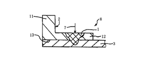
上記特許文献1に示されたところの従来技術の溶接構造を図3、図4を用いて説明する。図3は上記特許文献1に示されたところの溶接重ね継手の斜視図で、図4はその要部断面図を示している。図3、図4において、溶接重ね継手8は鍔部11と首部12とを持つフランジ部2と貫通穴を有するパイプ状の軸部3とから構成されていて、フランジ部2の穴13に軸部3が圧入されている。そして、首部12の部分でレーザ7を照射してのレーザ溶接された溶融部1おいてフランジ部2と軸部3とを溶着した構造を取っている。そして更に、溶融部1における希釈率(同一断面における、軸部3の溶融部面積/軸部3とフランジ部3との合計溶融部面積、とで表される)は15〜45%であることが好ましいとしている。
The conventional welding structure shown in Patent Document 1 will be described with reference to FIGS. FIG. 3 is a perspective view of the weld lap joint shown in Patent Document 1, and FIG. 4 is a cross-sectional view of the main part thereof. 3 and 4, the weld lap joint 8 is composed of a flange portion 2 having a
上記のレーザ溶接構造を取る溶接重ね継手8において、溶接重ね継手8を構成するところフランジ2にレーザ溶接を施すための首部12を設けた形状を取っている。即ち、首部12はレーザ溶接を施すために設けている。この首部12を設けたフランジ2はプレス加工方法などで成形することができず、太いパイプ材や丸棒から削り出しでもって成形することになる。従って、部品製作の加工方法が制限され、部品製作コストも高くなってくる。また、鍔部11の外径が大きくなってくると削り出しによる捨て去る材料分も多くなり、材料費のアップと共に材料費のムダも多く発生する。
In the weld lap joint 8 having the above laser welding structure, the weld lap joint 8 is configured to have a shape in which a
更に、狭い空間スペース内に配設して用いる場合に、スペースに余裕がなくて首部を設けた構造が取れない場合にはこの溶接構造は全く用いることはできない。従って、首部のない鍔部のみの形状で強い溶接接合が可能なレーザ溶接構造が望まれる。 Furthermore, when using it in a narrow space, this welded structure cannot be used at all if there is not enough space and a structure with a neck portion cannot be obtained. Therefore, there is a demand for a laser welding structure capable of strong welding joining with only the shape of the collar without a neck.
本発明は、上記課題に鑑みて成されたもので、その目的とする所は、シンプルな形状での鍔部材と軸部材との強い接合強度が得られるレーザ溶接構造を得ると共に、非常に安いコストで鍔付軸部材を製作できるようにすることにある。 The present invention has been made in view of the above problems, and the object of the present invention is to obtain a laser welding structure capable of obtaining a strong joint strength between a flange member and a shaft member in a simple shape, and very inexpensive. It is to be able to manufacture a flanged shaft member at a cost.
上記課題を解決するための手段として、本発明の鍔付軸部材は、軸部材に鍔部材が嵌着してなる鍔付軸部材において、鍔部材の両面側の嵌着部位もしくはいずれか一方の片面側の嵌着部位を斜め方向からレーザ照射して一周に渡って溶着したことを特徴とするものである。また、ここでの斜め方向からのレーザ照射角度は鍔部材の鍔面に対して30°〜70°とし、レーザ照射時間は1〜5secの連続照射であることを特徴とするものである。 As a means for solving the above-mentioned problems, the flanged shaft member of the present invention is a flanged shaft member in which the flange member is fitted to the shaft member. It is characterized in that the fitting part on one side is irradiated with laser from an oblique direction and welded over one round. Further, the laser irradiation angle from the oblique direction here is 30 ° to 70 ° with respect to the flange surface of the flange member, and the laser irradiation time is continuous irradiation of 1 to 5 seconds.
また、軸部材の外径を1.0〜5.0mmの範囲に制限すると共に、溶着部の深さを0.4〜0.8mmの範囲を好適とする。そして、軸部材及び鍔部材の溶着部が焼き戻しマルテンサイト組織になっいることを特徴とするものである。また、軸部材の材質は高炭素鋼であり、鍔部材の材質は高炭素鋼もしくはSUS材であることを特徴とする。 Further, the outer diameter of the shaft member is limited to a range of 1.0 to 5.0 mm, and the depth of the welded portion is preferably set to a range of 0.4 to 0.8 mm. And the welding part of a shaft member and a gutter member is a tempered martensite structure, It is characterized by the above-mentioned. Further, the shaft member is made of high carbon steel, and the collar member is made of high carbon steel or SUS material.
また、上記の鍔付軸部材の構成を得る本発明の製造方法は、軸部材に鍔部材が嵌着してなる鍔付軸部材の製造方法において、不活性ガス雰囲気の中で、鍔部材の両面側の嵌着部位、もしくはいずれか一方の片面側の嵌着部位を一周にわたって斜め方向から連続してレーザを照射して溶着させる工程と、溶着部の内部歪みを開放する焼き戻し工程と、
を有することを特徴とするものである。また、ここでの斜め方向からのレーザ照射角度は鍔部材の鍔面に対して30°〜70°であり、レーザ照射時間は1〜5secであることを特徴とするものである。そして、軸部材の外径をφ1.0〜5.0mmの範囲に制限し、溶着部の深さは0.4〜0.8mmの範囲を好適とするものである。また、溶着部の焼き戻しは180°〜220°Cの温度の中で1〜2時間行うことを特徴とするものである。
Further, the manufacturing method of the present invention for obtaining the configuration of the above-described flanged shaft member is a method for manufacturing a flanged shaft member in which the flange member is fitted to the shaft member. A process of irradiating a laser by continuously irradiating a laser beam from one side of the fitting part on either side, or one side of the fitting part, and a tempering process to release the internal distortion of the weld part;
It is characterized by having. Further, the laser irradiation angle from the oblique direction here is 30 ° to 70 ° with respect to the flange surface of the flange member, and the laser irradiation time is 1 to 5 seconds. And the outer diameter of a shaft member is restrict | limited to the range of (phi) 1.0-5.0mm, and the depth of a welding part makes the range of 0.4-0.8mm suitable. Further, the tempering of the welded portion is performed at a temperature of 180 ° to 220 ° C for 1 to 2 hours.
発明の効果として、本発明においては、鍔部材の両面側の嵌着部位もしくはいずれか一方の片面側の嵌着部位を斜め方向、30°〜70°の角度範囲からレーザ照射する。これによって、レーザ光が軸部材と鍔部材の両方に照射して双方の部材を溶融しての溶着が行われ、所要の溶着強度が得られる。30°より小さい角度にあると鍔部材の溶融部分が浅くなり、軸部材との溶着部分が少なくなって溶着強度が得られない。更に、30°より小さい角度にあると軸部材への溶融深度が深くなり、外径の小さい軸部材にあっては一周に渡ってレーザ照射を施すと溶融部分が繋がってしまい、加工時、その部分が強度的に弱くなって破損及び変形がし易くなる。逆に、照射角度が70°より大きくなると軸部材の径方向の溶融部分が浅くなり、鍔部材方向の溶融部分が広くなり、加工時、鍔部材の全幅に対する溶融部分が広くなることから鍔部材の固定力が小さくなり、位置ズレを起こしたり、鍔部材の変形を起こしたりする。また、レーザの照射時間は1〜5secの範囲で行われるが、1secより短いと溶融深度が浅くなり溶着強度不足が発生する。逆に、5secより長いと溶融深度が深くなり、外径の小さい軸部材にあっては一周に渡って溶融部分が繋がってしまい、その部分が強度的に弱くなって破損し易くなる。また、このレーザ照射時間は軸部材の外径に応じて最適な時間を設定するのが好ましい。 As an effect of the invention, in the present invention, a laser irradiation is performed from an angle range of 30 ° to 70 ° obliquely on the fitting portion on both sides of the flange member or the fitting portion on either one side. As a result, welding is performed by irradiating both the shaft member and the eave member with the laser beam to melt both members, and the required welding strength is obtained. When the angle is less than 30 °, the melted portion of the eaves member becomes shallow, and the welded portion with the shaft member is reduced, so that the welding strength cannot be obtained. Further, if the angle is smaller than 30 °, the melting depth to the shaft member becomes deep, and in the case of a shaft member having a small outer diameter, the laser beam is irradiated over the entire circumference and the melted portion is connected. The portion becomes weak in strength and is easily damaged and deformed. Conversely, when the irradiation angle is larger than 70 °, the radial melted portion of the shaft member becomes shallower, the melted portion in the heel member direction becomes wider, and the melted portion with respect to the full width of the heel member becomes wider during processing. As a result, the fixing force is reduced, causing positional displacement and deformation of the eaves member. The laser irradiation time is in the range of 1 to 5 seconds. If the laser irradiation time is shorter than 1 second, the melting depth becomes shallow, resulting in insufficient welding strength. On the contrary, if it is longer than 5 sec, the melting depth becomes deep, and in the shaft member having a small outer diameter, the melted portion is connected over the entire circumference, and the portion becomes weak in strength and easily broken. The laser irradiation time is preferably set to an optimum time according to the outer diameter of the shaft member.
また、本発明においては、軸部材の外径はφ1.0〜5.0mmの範囲に制限する。φ1.0mmより細くすると溶融部分が繋がってしまい、その部分は強度的に弱くなる。また、φ5.0mmより太くすると放熱が多過ぎるようになり一周に渡っての溶着が難しくなってくる。一周に渡る均一な溶着強度が必要で、溶着不十分による溶着強度不足部分が部分的に発生すると、その部分から亀裂などの破損が発生してくる。また、軸部材の外径がφ1.0〜5.0mmの範囲にあって、溶着部分の深さが0.4〜0.8mmの範囲にあると接合強度が強くなり満足する強度の溶着が得られる。 In the present invention, the outer diameter of the shaft member is limited to a range of φ1.0 to 5.0 mm. If it is made thinner than φ1.0 mm, the melted part is connected and the part becomes weak in strength. On the other hand, if it is thicker than φ5.0 mm, too much heat is dissipated, making it difficult to weld over one round. A uniform welding strength over one round is required, and when a portion with insufficient welding strength due to insufficient welding partially occurs, breakage such as a crack occurs from that portion. Further, when the outer diameter of the shaft member is in the range of φ1.0 to 5.0 mm and the depth of the welded portion is in the range of 0.4 to 0.8 mm, the bonding strength is increased and satisfactory welding is achieved. can get.
また、本発明における軸部材や鍔部材は耐強度性や耐摩耗性の必要性から炭素鋼あるいは高炭素鋼材料を使用する。そして、不活性ガス雰囲気の中で、鍔部材の両面側の嵌着部位、もしくはいずれか一方の片面側の嵌着部位を一周にわたって斜め方向から連続してレーザを照射して溶着させて軸部材と鍔部材とを接合する。レーザ照射により溶融した部分は高温焼き入れと冷却が短時間で行われることより針状組織のあるマルテンサイト組織に変質する。しかし、このマルテンサイト組織は内部応力が大きく、靱性も低いことから180°〜220°Cでの、1〜2時間の焼き戻しを行って内部応力を除去し、靱性を高める。これによって、溶融部分、即ち、溶着部分は焼き戻しマルテンサイト組織になって、硬度が硬く、強靱性があって耐摩耗性に強い鍔付の軸部材が得られる。また、レーザ照射は連続発振による連続照射で行うのでクラックやブローホールなどの発生の少ない溶着仕上がりを得ることができる。また、アルゴンガスやヘリウムガス、窒素ガスなどの不活性ガスを用いての雰囲気内、あるいは、これらの不活性ガスを吹き付けの中でレーザ照射することで溶着部分の金属酸化を防止している。 Further, the shaft member and the flange member in the present invention use carbon steel or high carbon steel material because of the necessity of strength resistance and wear resistance. Then, in an inert gas atmosphere, a shaft member is formed by continuously irradiating a laser beam on a fitting portion on both sides of the flange member or one of the fitting portions on one side of the flange member by irradiating the laser continuously from an oblique direction. And the heel member are joined. The part melted by the laser irradiation is transformed into a martensitic structure having a needle-like structure by performing high-temperature quenching and cooling in a short time. However, since this martensite structure has large internal stress and low toughness, it is tempered at 180 ° to 220 ° C. for 1 to 2 hours to remove internal stress and enhance toughness. As a result, the melted portion, that is, the welded portion has a tempered martensite structure, and a brazed shaft member having high hardness, high toughness, and high wear resistance is obtained. Further, since the laser irradiation is performed by continuous irradiation by continuous oscillation, it is possible to obtain a welding finish with less generation of cracks and blowholes. Further, the metal oxidation of the welded portion is prevented by irradiating laser in an atmosphere using an inert gas such as argon gas, helium gas or nitrogen gas, or while blowing these inert gas.
以上の製造方法を取って軸部材と鍔部材とを溶接接合して鍔付軸部材を構成することによって、炭素含有量の多い高炭素鋼であっても応力歪みのない状態で接合することが可能となる。また、鍔部材は平坦な板からなることからプレス加工方法などで簡単に製作できる。部品コストを非常に安くすることができる。 By taking the above manufacturing method and welding the shaft member and the flange member to form the flanged shaft member, even a high carbon steel with a high carbon content can be bonded without stress strain. It becomes possible. Further, since the eaves member is made of a flat plate, it can be easily manufactured by a press working method or the like. Parts cost can be made very cheap.
以下、本発明を実施するための最良の形態を図1、図2を用いて説明する。図1は本発明の実施形態に係る鍔付軸部材をレーザ照射している状態を模式的に描いた要部斜視図で、図2は図1に示す鍔付軸部材の要部断面図を示したものである。最初に、図1において、この鍔付軸部材20は、軸部材21と鍔部材22とから構成されていて、軸部材21と鍔部材22とを圧入などの方法で嵌着し、その嵌着部位をレーザ照射してレーザ溶接によって軸部材21と鍔部材22とを一体化した構造を取っている。ここでの軸部材21は丸棒のような形状に形成して摺動軸として用いている。鍔部材22は軸部材21と嵌着する穴22aを有して平板なるリング状の形状をなしている。また、軸部材21と鍔部材22は耐摩耗性や強靱性、耐蝕性などが要求されることから合金工具鋼や高速度工具鋼、マルテンサイト系ステンレス鋼などの焼き入れ処理ができる炭素含有量の多い材料を用いている。Aはレーザ光を示している。レーザー光Aの照射は、鍔部材22の穴22aに軸部材21を圧入などの方法で嵌着したコーナ部、即ち、鍔部材22の片側の鍔面22bと軸部材21とが交差した嵌着部位Oにθの角度から一周に渡って照射する方法を取っている。
The best mode for carrying out the present invention will be described below with reference to FIGS. FIG. 1 is a perspective view schematically showing a main part of a brazed shaft member according to an embodiment of the present invention, and FIG. 2 is a cross-sectional view of the main part of the brazed shaft member shown in FIG. It is shown. First, in FIG. 1, the
レーザはYAG(イットリウム・アルミニウム・ガーネット)レーザを用いる。レーザ発振器からのYAGレーザ光を光ファイバ26を介して出射ユニット25に導き、出射ユニット25からレーザ光Aを図1に示すθの角度の位置から照射する。この時、レーザ光Aの焦点は鍔部材22の鍔面22bと軸部材21とが交差した嵌着部位(コーナ部)Oの位置になるように設定している。
As the laser, a YAG (yttrium, aluminum, garnet) laser is used. The YAG laser light from the laser oscillator is guided to the emission unit 25 through the
レーザ溶接はアルゴンガスやヘリウムガス、窒素ガスなどの不活性ガスの雰囲気内、あるいは、これらの不活性ガスを吹き付けて行う。本実施形態においては、溶接ワーク(鍔付軸部材)を回転させながら行うことから、作業効率を考慮して大気圧の下で不活性ガスを吹き付けて行っている。溶接部位の酸化防止目的で不活性ガスを用いている。 Laser welding is performed in an atmosphere of an inert gas such as argon gas, helium gas, or nitrogen gas, or by blowing these inert gases. In this embodiment, since it is performed while rotating the welding work (brazed shaft member), the inert gas is blown under atmospheric pressure in consideration of work efficiency. An inert gas is used for the purpose of preventing oxidation at the welding site.
また、レーザ発振は連続発振で行う。即ち、レーザ光Aを連続的に出力して連続的に照射する方法を取る。この連続照射による溶接はクラックやブローホールの発生を抑え一周に渡って均一な溶接が得られる。また、小さい出力量で済む。 Laser oscillation is performed continuously. That is, the laser beam A is continuously output and continuously irradiated. The welding by this continuous irradiation suppresses the generation of cracks and blowholes, and a uniform welding can be obtained over one round. Also, a small output amount is sufficient.
この鍔付軸部材20のレーザ溶接は鍔付軸部材20を回転させながら行う。鍔付軸部材20の溶接位置が移動しないように位置を固定し、そして、鍔付軸部材20が一定の速度で回転する装置を用いて鍔付軸部材20を回転させる。
Laser welding of the brazed
溶着強度(溶接強度のことを云う。以降は溶接のことを溶着と表現して説明する)はレーザ光Aの照射角度θに強く影響を受ける。これは例えば、照射角度θが小さい角度であると軸部材21に対しては深い深度でもって溶融するが、鍔部材22に対する溶融部分は非常に少なくなる。そして、鍔部材22と軸部材21との溶着部分が少なくなって溶着強度は非常に弱くなってしまう。また、照射角度θを小さくすると鍔部材22の溶融幅が広がり、鍔部材22の熱放熱がし難くなり、鍔部材22の変形を起こしたり、鍔部材22の固定力が小さくなって位置ズレを起こしたりする。この照射角度θは鍔部材22の鍔面22bを基準にしての角度を指すが、本発明においては、この照射角度を30°〜70°の範囲を好適な範囲と設定する。この角度より外れると上記述べた如く溶着強度不足の問題が生じる。また、実験の結果では45°〜50°がより好適な範囲であることが判明した。
The welding strength (referred to as welding strength; hereinafter, welding will be described as welding) is strongly influenced by the irradiation angle θ of the laser beam A. For example, when the irradiation angle θ is a small angle, the
次に、本発明においては、軸部材21の外径dをφ1.0〜5.0mmに制限し、溶着深さtを0.4〜0.8mmに制限する。図2において、Cは溶着部を示しているが、この溶着部Cは、照射角度θからレーザ光Aを一周に渡って照射すると軸部材21の溶融部分21cと鍔部材22の溶融部分22cとが現れ、この溶融部分21cと溶融部分22cとが接合し合って溶着部Cが形成され。そして、この溶着部Cは一周に渡って形成される。この溶着部Cの深さtは溶着強度に影響を及ぼす。浅過ぎると溶着強度不足が起き、深過ぎると軸部材21において溶融部分21cが繋がってしまう。溶融部分が繋がると繋がった部分が脆くなり破断や曲がりなどが発生する。本発明においては、軸部材21の外径dがφ1.0〜5.0mmの下では溶着深さtは0.4〜0.8mmの範囲が所要の様着強度を得る上で好適な範囲になっている。
Next, in the present invention, the outer diameter d of the
溶着の深さはレーザ光の出力と照射時間によって決まってくる。出力を大きくすると溶融の深さを深くすることができ、また、照射時間を長くすると溶融の深さを深くすることができる。しかしながら反面、この照射時間と出力はクラックやブローホールの発生にも影響を及ぼす。従って、照射時間と出力は好適な範囲を設定しなければならない。本発明においては、軸部材21の外径dがφ1.0〜5.0mmの下で溶着深さtが0.4〜0.8mmの範囲が得られる照射時間としては1.0〜5.0secの範囲で行うのが良い。また、出力は200〜300Wの範囲で行うのが良い。この範囲の中で溶着強度、そして、クラックやブローホールの発生具合などを見て照射時間と出力量を適宜に設定するようにする。
The depth of welding is determined by the output of the laser beam and the irradiation time. When the output is increased, the melting depth can be increased, and when the irradiation time is lengthened, the melting depth can be increased. However, the irradiation time and output also affect the generation of cracks and blowholes. Therefore, it is necessary to set a suitable range for the irradiation time and output. In the present invention, the irradiation time for obtaining the range where the outer diameter d of the
次に、本発明の鍔付軸部材20の製造方法を説明する。本実施形態では大気中の中で窒素ガスを吹き付けながらレーザ照射を行っている。先ず、レーザ照射を行う前の準備として、軸部材21と鍔部材22とを嵌着した鍔付軸部材20を回転装置にレーザ光Aが鍔付軸部材20の嵌着部位Oの位置に照射する位置に固定する。また、レーザ光Aの出射ユニット25は30°〜70°の角度範囲の中で前もって設定したθの照射角度が得られる位置に、そして、レーザ光Aの焦点がOの位置にくる位置に予め固定しておく。そして、鍔付軸部材20を回転させながら一周に渡ってレーザ光AをOの位置に照射して溶着を施す。照射時間は1.0〜5.0secの範囲の中で予め設定した時間で行う。また、出力は200〜300Wの範囲の中で予め設定した出力で行う。
Next, the manufacturing method of the
レーザ照射が終わった後、鍔付軸部材20を焼成炉に入れ、180°〜220°Cの下で1〜2時間放置して焼き戻しを施す。これは、短時間のレーザ照射によって急熱と急冷が施されることから、溶着部分は針状組織を持ったマルテンサイト組織になり内部応力を持って、しかも、脆さのある状態になっている。この内部応力を除去すると同時に靱性を持たせるために180°〜220°C下で1〜2時間の焼き戻しを行うと溶着部分は針状組織のない焼き戻しマルテンサイト組織に変質する。そして、硬度が硬く耐摩耗性の良い、靱性の高い溶着が得られる。
After the laser irradiation is finished, the brazed
本実施形態においては、軸部材21と鍔部材22との溶着は鍔部材22の鍔面22b側で行っているが、鍔面22bの反対側の鍔面22e側で溶着を施しても良い。また、鍔面22bと22eの両側に溶着を施しても良い。両側に溶着を施すと尚一層の溶着強度が得られ、その接合強度は非常に強いものとなる。尚、両側で溶着を行う場合は、鍔部材22の溶融部分が繋がらない程度に十分な厚みを持った鍔部材を使用する。鍔部材22の厚み、溶着強度などを加味して両側溶着、片側溶着を選択すると良い。
In this embodiment, the
以上、レーザによる軸部材21と鍔部材22との溶着方法を説明したが、軸部材21及び鍔部材22の個々の部材全体に耐摩耗性や耐靱性が求められる場合は、それぞれ個々の部材(軸部材21、鍔部材22)を予め熱処理を施して硬度を硬くし、内部応力を除去した状態の部材にして使用する。この熱処理は800°〜850°Cの温度で部材を焼き入れし、180°〜200°Cの温度で1〜2時間の焼き戻し処理を行うことによって、硬度が高く耐摩耗性や耐靱性のある特性のものが得られる。そして、この様に熱処理の施された軸部材21と鍔部材22とを用いて上記の製造方法で溶着した鍔付軸部材20を形成する。
The method of welding the
本実施形態においては、軸部材21をフロートやプランジャーなどとして使用される丸棒形状で示したが、カム、歯車軸として使用される軸の両端が細径の軸形状であっても構わない。また更に、溶融深さを考慮されるならば円筒形状であっても構わない。
In the present embodiment, the
以上の製造方法を取ることにより溶着強度が強く、耐摩耗性や耐靱性のある鍔付軸部材を得ることができる。また、炭素含有量の多い高炭素鋼を用いてレーザ溶着して鍔付軸部材として用いることができる。軸部材は摺動軸として用いることから耐摩耗性や耐靱性を必要とするが、鍔部材は必ずしも軸部材と同等の特性を必要とするものではないので、その場合においては炭素含有量の少ない低炭素鋼を用いて鍔部材を形成しても何ら支障はない。また、鍔部材は平板状の形状でなることからプレス加工方法で簡単に形成することができる。また、量産が可能であることから製造コストは非常に安くすることができる。また、狭い空間スペースの中で十分利用することが可能になる。また、鍔部材が平板状を取ることにより、色々な形状のものをプレス加工方法でもって形成することができる。例えば、外形形状が四角や六角の形状のもの、鍔面に貫通穴を設けた形状のもの、鍔面に凹凸を設けた形状のもの、などを容易に形成することができる。 By adopting the above manufacturing method, it is possible to obtain a brazed shaft member having high welding strength and wear resistance and toughness. Further, it can be used as a brazed shaft member by laser welding using high carbon steel having a high carbon content. Since the shaft member is used as a sliding shaft, it requires wear resistance and toughness. However, since the eaves member does not necessarily have the same characteristics as the shaft member, the carbon content is low in that case. There is no problem even if the saddle member is formed using low carbon steel. Further, since the eaves member has a flat plate shape, it can be easily formed by a press working method. Further, since the mass production is possible, the manufacturing cost can be very low. Moreover, it becomes possible to fully utilize in a narrow space. Moreover, when the eaves member has a flat plate shape, various shapes can be formed by a pressing method. For example, it is possible to easily form an outer shape having a square or hexagonal shape, a shape in which a through hole is provided on the flange surface, or a shape having irregularities on the flange surface.
本発明の実施例1として、軸部材と鍔部材は次の仕様のものを用いて鍔付軸部材を形成した。
軸部材・・・・材質:SK4、寸法:外形φ1.6mm、長さ34mm、切削加工でブランク製作後、熱処理(焼き入れ、焼き戻し)により硬度Hv750にし、バレル研磨とメッキを施して軸部材を形成。
鍔部材・・・・材質:SK4、寸法:外形φ3.2mm、厚み0.7mm、プレス加工でブランク製作後、熱処理(焼き入れ、焼き戻し)により硬度Hv750にし、バレル研磨とメッキを施して鍔部材を形成。
上記の軸部材と鍔部材を圧入方法にて嵌着し、片側のみのレーザ照射を行う。レーザ照射は、照射角度45°、出力260Wで照射時間は2.5secの照射を行い、その後に200°C、2時間の焼き戻しを行った。結果は、溶着の深さは0.65mmの深さが得られ所要の溶着強度が得られた。また、クラックやブローホールの発生は見受けられず、評価はOKの判定であった。
As Example 1 of this invention, the shaft member and the collar member formed the shaft member with a collar using the thing of the following specification.
Shaft member ··· Material: SK4, Dimensions: External diameter φ1.6mm, length 34mm, blank production by cutting, hardness Hv750 by heat treatment (quenching, tempering), barrel polishing and plating, shaft member Forming.
鍔 Material: ・ ・ ・ Material: SK4, Dimensions: φ3.2mm, Thickness 0.7mm, Blank production by press working, hardness Hv750 by heat treatment (quenching, tempering), barrel polishing and plating Form members.
The shaft member and the flange member are fitted by a press-fitting method, and laser irradiation is performed only on one side. Laser irradiation was performed at an irradiation angle of 45 °, an output of 260 W, and an irradiation time of 2.5 seconds, followed by tempering at 200 ° C. for 2 hours. As a result, the depth of welding was 0.65 mm, and the required welding strength was obtained. Moreover, the generation | occurrence | production of a crack and a blowhole was not seen, and evaluation was the determination of OK.
実施例1にあって、鍔部材にSK4の高炭素鋼を用いたが、SUSなどの材質の違った材料を使用しても構わない。SUS材を使用した場合は溶着部の酸化が防止でき、後工程にて防錆のための再メッキをしなくて済む。 In Example 1, high carbon steel of SK4 is used for the eaves member, but materials such as SUS may be used. When the SUS material is used, oxidation of the welded portion can be prevented, and re-plating for rust prevention is not necessary in the subsequent process.
実施例2は、実施例1と同じ仕様の軸部材と鍔部材を用いて、レーザ照射条件を変えた。照射角度は45°、出力220Wの下で4.5secの照射を行い、その後に、200°C、2時間の焼き戻しを行った。結果は、溶着の深さは0.60mmの深さが得られ、所要の溶着強度が得られた。また、クラックやブローホールの発生は見受けられず、評価はOKの判定であった。 In Example 2, the laser irradiation conditions were changed using a shaft member and a flange member having the same specifications as those in Example 1. Irradiation was performed at an irradiation angle of 45 ° and an output of 220 W for 4.5 sec, and then tempering was performed at 200 ° C. for 2 hours. As a result, the depth of welding was 0.60 mm, and the required welding strength was obtained. Moreover, the generation | occurrence | production of a crack and a blowhole was not seen, and evaluation was the determination of OK.
20 鍔付軸部材
21 軸部材
22 鍔部材
22a 穴
22b、22e 鍔面
25 出射ユニット
26 光ファイバー
A レーザ光
C 溶着部
θ 照射角度
t 深さ
d 外径
20
Claims (11)
不活性ガス雰囲気の中で、前記鍔部材の両面側の嵌着部位、もしくはいずれか一方の片面側の嵌着部位を一周にわたって斜め方向から連続してレーザを照射して溶着させる工程と、
前記溶着部の内部歪みを開放する焼き戻し工程と、
を有することを特徴とする鍔付軸部材の製造方法。 In the manufacturing method of the flanged shaft member formed by fitting the flange member to the shaft member,
In an inert gas atmosphere, the step of welding by irradiating a laser continuously from one side of the fitting portion on both sides of the flange member, or one of the fitting portions on one side, from an oblique direction;
A tempering step for releasing internal distortion of the welded portion;
The manufacturing method of the shaft member with a flange characterized by having.
Priority Applications (1)
| Application Number | Priority Date | Filing Date | Title |
|---|---|---|---|
| JP2005097710A JP2006272425A (en) | 2005-03-30 | 2005-03-30 | Flanged shaft member and its manufacturing method |
Applications Claiming Priority (1)
| Application Number | Priority Date | Filing Date | Title |
|---|---|---|---|
| JP2005097710A JP2006272425A (en) | 2005-03-30 | 2005-03-30 | Flanged shaft member and its manufacturing method |
Publications (1)
| Publication Number | Publication Date |
|---|---|
| JP2006272425A true JP2006272425A (en) | 2006-10-12 |
Family
ID=37207660
Family Applications (1)
| Application Number | Title | Priority Date | Filing Date |
|---|---|---|---|
| JP2005097710A Pending JP2006272425A (en) | 2005-03-30 | 2005-03-30 | Flanged shaft member and its manufacturing method |
Country Status (1)
| Country | Link |
|---|---|
| JP (1) | JP2006272425A (en) |
Cited By (1)
| Publication number | Priority date | Publication date | Assignee | Title |
|---|---|---|---|---|
| CN112189297A (en) * | 2018-05-30 | 2021-01-05 | 美蓓亚三美株式会社 | Motor and manufacturing method of motor |
-
2005
- 2005-03-30 JP JP2005097710A patent/JP2006272425A/en active Pending
Cited By (2)
| Publication number | Priority date | Publication date | Assignee | Title |
|---|---|---|---|---|
| CN112189297A (en) * | 2018-05-30 | 2021-01-05 | 美蓓亚三美株式会社 | Motor and manufacturing method of motor |
| US11735977B2 (en) | 2018-05-30 | 2023-08-22 | Minebea Mitsumi Inc. | Motor and manufacturing method of motor |
Similar Documents
| Publication | Publication Date | Title |
|---|---|---|
| US5211327A (en) | Method of welding | |
| JP5024475B1 (en) | Laser welded steel pipe manufacturing method | |
| JP6497451B2 (en) | Friction stir welding method and apparatus | |
| KR101954561B1 (en) | Friction stir welding apparatus for structural steel | |
| KR102098217B1 (en) | Method and apparatus for friction stir welding of structural steel | |
| KR102096919B1 (en) | Method and apparatus for friction stir welding of structural steel | |
| JP5866790B2 (en) | Laser welded steel pipe manufacturing method | |
| JP2007203330A (en) | Laser welding method | |
| JP2006272425A (en) | Flanged shaft member and its manufacturing method | |
| JP2004082144A (en) | Tool and method for friction stir welding | |
| JP4518892B2 (en) | Dissimilar material joining method | |
| JP2003266182A (en) | Friction stir welding method for different kind of metallic material | |
| JP5760951B2 (en) | Laser welding method | |
| JP2010105037A (en) | Hollow joined body and method for producing the same, and joining device | |
| JP6684548B2 (en) | Chip joining method | |
| JP6493564B2 (en) | Friction stir welding method and apparatus | |
| TW201443237A (en) | Method for manufacturing cutting tool | |
| JP2013154398A (en) | Butt joining method for dissimilar metal | |
| JPH0236357B2 (en) | ||
| US20230294206A1 (en) | Laser welding method for joining a non-sintered material to a sintered material, composite body, and use of a laser welding method | |
| JP2010052007A (en) | Laser brazing method | |
| JP4957271B2 (en) | Laser brazing method | |
| JP2014014850A (en) | Pipe joining method by brazing | |
| KR101385151B1 (en) | Method for brazing dissimilar metals using laser | |
| JP2010247194A (en) | Method of joining metallic tube |