JP2006266476A - Tapping bolt - Google Patents
Tapping bolt Download PDFInfo
- Publication number
- JP2006266476A JP2006266476A JP2005089571A JP2005089571A JP2006266476A JP 2006266476 A JP2006266476 A JP 2006266476A JP 2005089571 A JP2005089571 A JP 2005089571A JP 2005089571 A JP2005089571 A JP 2005089571A JP 2006266476 A JP2006266476 A JP 2006266476A
- Authority
- JP
- Japan
- Prior art keywords
- thread
- screw
- threads
- tapping bolt
- shaft portion
- Prior art date
- Legal status (The legal status is an assumption and is not a legal conclusion. Google has not performed a legal analysis and makes no representation as to the accuracy of the status listed.)
- Pending
Links
Images


Abstract
Description
この発明は、ALC等のコンクリート製品にねじ込むタッピングボルトに関するものである。 The present invention relates to a tapping bolt screwed into a concrete product such as ALC.
ALC(気泡コンクリート製品)、モルタル、アスファルト、レンガ、鉄筋コンクリート等から成るコンクリート製品に対して適宜の物品(取付け対象物)をボルト止めすることは従来から普通に行なわれているが、コンクリート製品に対して直接ねじ込むことができるようにしたボルトは未だ存在しない。 Conventionally, bolting appropriate articles (attachment objects) to concrete products made of ALC (cellular concrete products), mortar, asphalt, bricks, reinforced concrete, etc. There is still no bolt that can be screwed in directly.
そこで、取付け対象物のボルト止めに際し、従来では、軸方向のスリットを有する筒体と、その筒体内に組込まれたテーパ状のナットとから成るアンカーを用い、そのアンカーをコンクリート製品に形成された下孔内に挿入し、上記ナットにねじ込まれるボルトの締付けによりナットを軸方向に移動させて筒体を拡径させ、下孔の内周に筒体の外周を圧接係合させて筒体およびナットの固定化を図り、上記ナットに対してボルトを締付けることが一般的であった。 Therefore, when bolting an object to be attached, conventionally, an anchor composed of a cylindrical body having an axial slit and a tapered nut incorporated in the cylindrical body was used, and the anchor was formed on a concrete product. By inserting the nut into the lower hole and tightening the bolt screwed into the nut, the nut is moved in the axial direction to expand the diameter of the cylinder, and the outer periphery of the cylinder is press-fitted to the inner periphery of the lower hole to It has been common to fix the nut and tighten the bolt to the nut.
ところで、アンカーを用いる取付け対象物の固定にはコストが高く、しかも、ボルトを強く締め付けた場合にアンカーが下孔から抜け出るおそれがあり、取付け対象物を強固に固定することができないという問題がある。 By the way, there is a problem that fixing of an attachment object using an anchor is expensive, and there is a possibility that the anchor may come out of the pilot hole when the bolt is strongly tightened, and the attachment object cannot be firmly fixed. .
ここで、一般的に知られているボルトは雄ねじのねじ山が隣接するねじ山間にV形の谷底が形成された構成であるため、そのようなボルトをコンクリート製品に形成された下孔にねじ込むと、ねじ山に対してきわめて大きな摩擦抵抗が作用し、その摩擦抵抗は締付け時の回転抵抗となるため、締付けにきわめて大きな回転トルクを必要とし、ときには焼付きが生じてロックするという問題が生じる。 Here, since a generally known bolt has a configuration in which a V-shaped valley bottom is formed between adjacent threads of a male screw, such a bolt is screwed into a prepared hole formed in a concrete product. Then, an extremely large frictional resistance acts on the screw thread, and the frictional resistance becomes a rotational resistance at the time of tightening, so that a very large rotational torque is required for tightening, sometimes causing seizure and locking. .
また、下孔の内周に雌ねじを形成しつつねじ込むことができるようにしたタッピングねじも従来から知られているが、そのタッピングねじがねじ込まれる対象物は金属や合成樹脂から成る製品であって、コンクリート製品類にねじ込んだ場合、雄ねじが摩耗して完全な雌ねじを形成することができず、引抜き耐力がきわめて低く取付け対象物を安定よく取付けることができない。 In addition, a tapping screw that can be screwed in while forming a female screw on the inner periphery of the pilot hole is conventionally known, but the object into which the tapping screw is screwed is a product made of metal or synthetic resin. When it is screwed into concrete products, the male screw is worn away and a complete female screw cannot be formed, and the drawing strength is extremely low, so that the object to be attached cannot be stably attached.
この発明の課題は、コンクリート製品に直接ねじ込むことができるようにしたコンクリート製品用のタッピングボルトを提供することである。 It is an object of the present invention to provide a tapping bolt for a concrete product that can be directly screwed into the concrete product.
上記の課題を解決するために、この発明においては、先端にテーパ部を有する軸部の外周に、ねじ山の形が三角形の雄ねじを隣接するねじ山間に間隔をあけて設け、その雄ねじのねじ山の角度を軸部の先端に位置するねじ山から後端に位置するねじ山に至るに従って次第に大きくした構成を採用したのである。 In order to solve the above-described problems, in the present invention, a male screw having a triangular thread shape is provided on the outer periphery of a shaft portion having a tapered portion at the tip, with a space between adjacent screw threads. A configuration is adopted in which the angle of the crest is gradually increased from the thread located at the front end of the shaft portion to the thread located at the rear end.
ここで、雄ねじのねじ山は、軸部先端から後端に向けて1山ごとに角度を大きくしてもよく、あるいは、雄ねじのねじ山を複数のねじ山ごとにグループ分けし、同一グループのねじ山の角度を同一とし、軸部の先端に位置する第1グループから軸部の後端部に至る第nグループに向けてねじ山の角度を次第に大きくしてもよい。 Here, the thread of the male screw may have a larger angle for each thread from the front end to the rear end of the shaft. Alternatively, the thread of the male thread may be grouped into a plurality of threads and The angle of the thread may be the same, and the angle of the thread may be gradually increased toward the nth group from the first group located at the tip of the shaft to the rear end of the shaft.
上記の構成から成るタッピングボルトのねじ込みに際して、コンクリート製品がALCから成る場合は、そのALCに直接ねじ込むようにしてもよく、あるいは、ALCに下孔を形成し、その下孔にねじ込むようにしてもよい。 When the tapping bolt having the above structure is screwed, if the concrete product is made of ALC, it may be screwed directly into the ALC, or a pilot hole may be formed in the ALC and screwed into the pilot hole. Good.
ALCより硬度の高いコンクリート製品に対しては、そのコンクリート製品に下孔を形成してねじ込むようにする。 For concrete products with higher hardness than ALC, a pilot hole is formed in the concrete product and screwed.
ここで、軸部の外周に、その先端から軸方向に延びてねじ山を周方向に分断するスリットを形成しておくと、雄ねじのねじ込み時に発生する切り粉をスリット内に収容することができるため、回転抵抗の低減化を図ることができると共に、軸部は回転抵抗が大きくなると縮径するため、スムーズなねじ込みを可能とすることができる。 Here, if a slit is formed on the outer periphery of the shaft portion so as to extend in the axial direction from the tip thereof and divide the thread in the circumferential direction, chips generated when the male screw is screwed can be accommodated in the slit. Therefore, the rotational resistance can be reduced, and the shaft portion is reduced in diameter when the rotational resistance is increased, so that smooth screwing can be achieved.
なお、スリットの幅および深さは軸部の外径やコンクリート製品の硬度に応じて適宜に決定し、深さについては、軸部の外周対向位置で開口して軸部の先端部に二股片を形成するようなものであってもよい。また、スリットは軸心に平行する直線状のものであってもよく、あるいはスパイラル状のものであってもよい。 The width and depth of the slit are appropriately determined according to the outer diameter of the shaft portion and the hardness of the concrete product, and the depth is opened at a position facing the outer periphery of the shaft portion, and a forked piece at the tip portion of the shaft portion. May be formed. The slit may be a straight line parallel to the axis or may be a spiral.
この発明に係るタッピングボルトにおいて、前記雄ねじに、軸部先端のねじ山から少なくとも複数のねじ山を周方向に複数に分断する複数の溝を形成すると、複数に分断された分割ねじ山のねじ込み時における回転方向の先行側端面のエッジが切り刃の役目をし、その切り刃の切り込みによって発生する切り粉を溝内に収容することができるため、ねじ込み時の回転抵抗は小さく、コンクリート製品に対してスムーズにねじ込むことができる。 In the tapping bolt according to the present invention, when a plurality of grooves that divide at least a plurality of threads in the circumferential direction from the thread at the end of the shaft portion are formed in the male thread in the circumferential direction, the plurality of divided threads are screwed in The edge of the leading end surface in the rotation direction of the metal acts as a cutting blade, and the chips generated by the cutting of the cutting blade can be accommodated in the groove. And can be screwed in smoothly.
上記のように、雄ねじのねじ山の角度を軸部の先端から後端に至るに従って次第に大きくしたことにより、コンクリート製品に対するねじ込み時、軸部先端側の先行側のねじ山がコンクリート製品との接触により摩耗してコンクリート製品に切削される雌ねじが不完全なものであっても、後行側のねじ山は先行側ねじ山により切削された雌ねじに沿って侵入するため、後行側のねじ山によって完全な雌ねじが切削されることになり、コンクリート製品に対してタッピングボルトを確実にねじ込むことができる。 As described above, the thread angle of the male thread is gradually increased from the front end of the shaft to the rear end, so that when the screw is screwed into the concrete product, the screw thread on the front side of the shaft is in contact with the concrete product. Even if the internal thread cut into the concrete product due to abrasion is incomplete, the subsequent thread penetrates along the internal thread cut by the preceding thread, so the subsequent thread As a result, a complete female screw is cut, and the tapping bolt can be reliably screwed into the concrete product.
また、後行側のねじ山の角度を先行側のねじ山の角度より大きくしたことにより、後行側のねじ山は先行側のねじ山によって形成される雌ねじの両側のフランクを切削しつつ侵入する。このため、雌ねじと後行側ねじ山の係合力は強く、雄ねじの先行側のねじ山が摩耗してねじ係合することがない場合であっても後行側の複数のねじ山によって充分な引き抜き耐力を得ることができ、取付け対象物を強固に取付けることができる。 Also, by making the angle of the thread on the trailing side larger than the angle of the thread on the leading side, the thread on the trailing side penetrates while cutting the flank on both sides of the female thread formed by the thread on the leading side. To do. For this reason, the engagement force between the female screw and the succeeding screw thread is strong, and even if the leading screw thread of the male screw wears out and does not engage with the screw, it is sufficient by the plurality of succeeding screw threads. The pulling strength can be obtained, and the object to be attached can be firmly attached.
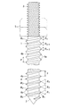
以下、この発明の実施形態を図面に基づいて説明する。図1はこの発明に係るタッピングボルトの第1の実施形態を示す。図示のように、軸部1はテーパ部2を先端に有し、後端部にはねじ軸部3が設けられている。
Embodiments of the present invention will be described below with reference to the drawings. FIG. 1 shows a first embodiment of a tapping bolt according to the present invention. As shown in the figure, the
軸部1の外周には、先端から後端に至って雄ねじ4が転造により形成され、そのねじ形成後、熱処理されて硬度が高められている。雄ねじ4はねじ山4aの形が三角形とされ、隣接するねじ山4a間に間隔が形成されて谷底4bはストレートとされている。
On the outer periphery of the
ここで、軸部1の先端側からのねじ山4aを第1ねじ山a1乃至第nねじ山anとし、その第1ねじ山a1乃至第nねじ山anの角度をθ1乃至θnとすると、そのねじ山の角度θ1乃至θnは、第1ねじ山a1から第nねじ山anに至るに従って次第に大きくなっている。
Here, the
実施の形態では、第1ねじ山a1の角度θ1を60°として、第nねじ山anに向けて1°ずつ大きくし、第nねじ山anの角度θnを90°としているが、第1ねじ山a1の角度θ1、隣接するねじ山4aの角度差および第nねじ山anの角度θnはこれに限定されず、コンクリート製品の硬度に応じて適宜に決定する。また、ねじ山4aのピッチPは一定とし、そのピッチPもコンクリート製品に応じて適宜に決定する。
In the embodiment, the angle theta 1 of the first thread a 1 as 60 °, toward the first n threads a n increased by 1 °, and the angle theta n of the n threads a n and 90 ° but the angle theta 1 of the first thread a 1, the angle theta n of the angular difference and the n threads a n
第1の実施形態で示すタッピングボルトは上記の構造から成り、コンクリート製品に対するねじ込みに際し、そのコンクリート製品がALC等の比較的硬度の低いコンクリート製品の場合は、そのコンクリート製品に直接ねじ込むようにしてもよく、あるいは上記コンクリート製品にタッピングボルトの谷径と略同径の下孔を形成してその下孔にねじ込むようにしてもよい。一方、硬度の高いコンクリート製品の場合は、下孔を形成してねじ込むようにする。そのねじ込みに際しては、ねじ軸部3に2個のナット5をねじ込み、そのナット5の相対回転によりナット5の衝合面の面圧を高めて2個のナット5をねじ軸部3に固定し、そのナット5にレンチを係合してタッピングボルトに締付け方向の回転トルクを負荷する。
The tapping bolt shown in the first embodiment has the above structure. When the concrete product is screwed into a concrete product, if the concrete product is a concrete product with a relatively low hardness such as ALC, the tapping bolt may be screwed directly into the concrete product. Alternatively, a pilot hole having a diameter substantially the same as the valley diameter of the tapping bolt may be formed in the concrete product and screwed into the pilot hole. On the other hand, in the case of a concrete product with high hardness, a pilot hole is formed and screwed. At the time of screwing, two nuts 5 are screwed into the
いま、コンクリート製品に形成された下孔にタッピングボルトをねじ込むと、雄ねじ4によって下孔の内周が切削されて雌ねじが形成される。このとき、軸部1先端の先行側のねじ山は下孔の内周との接触によって摩耗し易く、その摩耗によって下孔の内周に不完全な雌ねじが形成されるが、後行側のねじ山aは先行側のねじ山4aによって形成された雌ねじに沿って侵入するため、後行側のねじ山4aによる切削によって完全な雌ねじが形成されることになる。このとき、後行側のねじ4aは先行側のねじ山4aより角度が次第に大きくなっているため、後行側のねじ山4aは先行側のねじ山4aによって形成された雌ねじの両側フランクを切削しつつ侵入することになる。このため、雌ねじと後行側のねじ山4aの係合力は強く、先行側のねじ山4aが摩耗してねじ係合することがない場合であっても後行側の複数のねじ山4aによって充分な引き抜き耐力を得ることができ、強固なねじ込み状態を得ることができる。
Now, when the tapping bolt is screwed into the prepared hole formed in the concrete product, the inner periphery of the prepared hole is cut by the
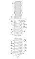
図2は、この発明に係るタッピングボルトの第2の実施形態を示す。この実施形態では、軸部1の後端にフランジ6を設け、そのフランジ6にねじ軸部3を設けている点で第1の実施形態と相違する。このため、第1の実施形態と同一部分には同一の符号を付して説明を省略する。
FIG. 2 shows a second embodiment of a tapping bolt according to the present invention. This embodiment is different from the first embodiment in that a flange 6 is provided at the rear end of the
第2の実施形態で示すタッピングボルトのように、軸部1の後端にフランジ6を形成すると、そのフランジ6によってタッピングボルトの締付け量を制限することができる。
When the flange 6 is formed at the rear end of the
図3は、この発明に係るタッピングボルトの第3の実施形態を示す。この実施形態では、軸部1の外周に形成された雄ねじ4のねじ山4aを複数のねじ山毎に第1グループG1乃至第nグループ(図示省略)にグループ分けし、同一グループの複数のねじ山4aの角度θ1、θ2…θnを同一とし、軸部1の先端側に位置する第1グループG1から軸部1の後端部に至る第nグループに向けてねじ山4aの角度θ1、θ2…θnを次第に大きくしている。
FIG. 3 shows a third embodiment of the tapping bolt according to the present invention. In this embodiment, grouped first group G 1 through n-th group (not shown) the
他の構成は第1の実施形態と同一であるため、同一部分には同一符号を付して説明を省略する。 Since other configurations are the same as those of the first embodiment, the same portions are denoted by the same reference numerals and description thereof is omitted.
上記第3の実施形態で示すタッピングボルトにおいても、第1の実施形態と同様に、コンクリート製品に対して確実にねじ込むことができると共に、充分な引き抜き耐力を得ることができる。 As with the first embodiment, the tapping bolt shown in the third embodiment can be reliably screwed into the concrete product and can have sufficient pulling strength.
図4および図5はこの発明に係るタッピングボルトの第4の実施形態を示す。この実施形態では、軸部1の外周にその先端から後端部に延びてねじ山4aを周方向に分断するスリット7を設けている点で第1の実施形態と相違している。
4 and 5 show a fourth embodiment of a tapping bolt according to the present invention. This embodiment is different from the first embodiment in that a
このため、第1の実施形態と同一部分には同一の符号を付して説明を省略する。 For this reason, the same parts as those in the first embodiment are denoted by the same reference numerals, and description thereof is omitted.
第4の実施形態で示すように、軸部1の先端部にスリット7を形成すると、雄ねじ4のねじ込み時に切削によって発生する切り粉をスリット7内に収容することができるため、ボルトねじ込み時の回転抵抗の低減化を図ることができる。また、回転抵抗が大きくなると、軸部1は縮径するため、スムーズなねじ込みを可能とすることができる。
As shown in the fourth embodiment, when the
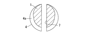
ここで、スリット7の幅および深さは、軸部1の外径やコンクリート製品の硬度に応じて適宜に決定すればよい。深さについては、図5に示すように、軸部1の中心部に至るものであってよく、あるいは図6に示すように、軸部1の外周一側から軸部1の外周他側に貫通するものであってもよい。
Here, the width and depth of the
図7および図8は、この発明に係るタッピングボルトの第5の実施形態を示す。この実施形態では、軸部1の外周に形成された雄ねじ4の軸部先端のねじ山4aから少なくとも複数のねじ山4aを周方向に分断する複数の溝8を形成している。
7 and 8 show a fifth embodiment of a tapping bolt according to the present invention. In this embodiment, a plurality of
上記のように、複数の溝8を形成すると、複数に分断された分割ねじ山4a’のねじ込み時における回転方向の先行側の端面のエッジ9が切り刃の役目をし、その切り刃が下孔の内周を切り込みつつコンクリート内部に侵入すると共に、切り込みによって発生する切り粉は溝8内に収容されるため、ねじ込み時の回転抵抗は小さく、コンクリート製品に対してタッピングボルトをきわめてスムーズにねじ込むことができる。
As described above, when the plurality of
第1の実施形態乃至第5の実施形態で示すタッピングボルトをコンクリート製品に形成された下孔に対してねじ込む場合において、その下孔にエポキシ樹脂等の溶融樹脂と硬化剤の混合液状体を入れてねじ込み作業を行なうと、混合液状体が潤滑剤の役目をするため、タッピングボルトをスムーズにねじ込むことができる。 When the tapping bolt shown in the first to fifth embodiments is screwed into the lower hole formed in the concrete product, a mixed liquid of a molten resin such as epoxy resin and a curing agent is put in the lower hole. When the screwing operation is performed, the mixed liquid serves as a lubricant, so that the tapping bolt can be screwed smoothly.
また、液状体は雄ねじ4と、その雄ねじ4によって形成される雌ねじのねじ係合部間や下孔とタッピングボルト間の隙間に侵入して固化するため、タッピングボルトを弛み止めすることができる。この場合、樹脂として、固化時に膨張する樹脂を採用すると、タッピングボルトをより確実に弛み止めすることができる。
Further, since the liquid material enters and solidifies between the
第1の実施形態では、軸部1の後端にねじ軸部3を設けたが、ねじ軸部3に代えて、六角頭部などのレンチ係合用の頭部を形成してもよく、あるいは軸部1の後端面に角孔を形成してもよい。
In the first embodiment, the
また、第1の実施形態では、軸部1として全長にわたって同一径のストレート軸部を示したが、先端又は後端を大径端とするテーパ軸部であってもよい。
In the first embodiment, the straight shaft portion having the same diameter over the entire length is shown as the
1 軸部
2 テーパ部
4 雄ねじ
4a ねじ山
7 スリット
8 溝
1
Claims (4)
Priority Applications (1)
| Application Number | Priority Date | Filing Date | Title |
|---|---|---|---|
| JP2005089571A JP2006266476A (en) | 2005-03-25 | 2005-03-25 | Tapping bolt |
Applications Claiming Priority (1)
| Application Number | Priority Date | Filing Date | Title |
|---|---|---|---|
| JP2005089571A JP2006266476A (en) | 2005-03-25 | 2005-03-25 | Tapping bolt |
Publications (1)
| Publication Number | Publication Date |
|---|---|
| JP2006266476A true JP2006266476A (en) | 2006-10-05 |
Family
ID=37202664
Family Applications (1)
| Application Number | Title | Priority Date | Filing Date |
|---|---|---|---|
| JP2005089571A Pending JP2006266476A (en) | 2005-03-25 | 2005-03-25 | Tapping bolt |
Country Status (1)
| Country | Link |
|---|---|
| JP (1) | JP2006266476A (en) |
Cited By (2)
| Publication number | Priority date | Publication date | Assignee | Title |
|---|---|---|---|---|
| KR100891371B1 (en) * | 2007-05-31 | 2009-04-02 | 김종성 | Ancher bolt |
| JP2012251654A (en) * | 2011-06-01 | 2012-12-20 | Takayuki Sato | Easy-to-attach anchor bolt |
-
2005
- 2005-03-25 JP JP2005089571A patent/JP2006266476A/en active Pending
Cited By (2)
| Publication number | Priority date | Publication date | Assignee | Title |
|---|---|---|---|---|
| KR100891371B1 (en) * | 2007-05-31 | 2009-04-02 | 김종성 | Ancher bolt |
| JP2012251654A (en) * | 2011-06-01 | 2012-12-20 | Takayuki Sato | Easy-to-attach anchor bolt |
Similar Documents
| Publication | Publication Date | Title |
|---|---|---|
| US10247219B2 (en) | Screw-type fastener | |
| EP2679835B1 (en) | Threaded fastener | |
| CN107923428B (en) | Threaded fastener | |
| US20050191152A1 (en) | Bolt & Nut | |
| US6322307B1 (en) | Fixing anchor | |
| EP2700829B1 (en) | Tapping screw | |
| JP4225546B2 (en) | Tapping screw | |
| US11204055B2 (en) | Sheet metal screw | |
| JPWO2012102401A1 (en) | Female thread structure | |
| US11703074B2 (en) | Thread-forming or self-tapping screw, in particular for use in light metal | |
| JP2006266476A (en) | Tapping bolt | |
| CA3081395C (en) | Screw-type fastener | |
| JP2007321930A (en) | Tapping screw for fastening sheet | |
| JP6871595B2 (en) | Double screw construction | |
| JP5299816B2 (en) | nut | |
| JP3138712U (en) | Tapping bolt | |
| JP2004190713A (en) | Locking screw | |
| JP2006177405A (en) | Concrete product tapping bolt | |
| KR102185997B1 (en) | Taping Screw | |
| US20220090622A1 (en) | Fastener arrangement for establishing a screw connection | |
| US11619252B2 (en) | Wallboard anchor | |
| JP2009063144A (en) | Self-drilling screw, self-drilling anchor, and method of manufacturing self-drilling anchor | |
| WO2013180239A1 (en) | Self-tapping screw and attachment structure thereof | |
| JP2002106538A (en) | Screw part having locking function | |
| JP6282160B2 (en) | Drill screw |