JP2006260010A - Apparatus and method for controlling robot, and computer program - Google Patents
Apparatus and method for controlling robot, and computer program Download PDFInfo
- Publication number
- JP2006260010A JP2006260010A JP2005075026A JP2005075026A JP2006260010A JP 2006260010 A JP2006260010 A JP 2006260010A JP 2005075026 A JP2005075026 A JP 2005075026A JP 2005075026 A JP2005075026 A JP 2005075026A JP 2006260010 A JP2006260010 A JP 2006260010A
- Authority
- JP
- Japan
- Prior art keywords
- arm
- axis
- target position
- robot
- tip
- Prior art date
- Legal status (The legal status is an assumption and is not a legal conclusion. Google has not performed a legal analysis and makes no representation as to the accuracy of the status listed.)
- Granted
Links
Images


Landscapes
- Numerical Control (AREA)
- Manipulator (AREA)
Abstract
Description
本発明は、走行軸を冗長軸とし、垂直多関節型で6軸のアームを有するロボットの制御を行う制御装置及び制御方法、並びに前記制御装置を構成するコンピュータにより実行されるプログラムに関する。 The present invention relates to a control apparatus and a control method for controlling a robot having a traveling axis as a redundant axis and a vertical articulated 6-axis arm, and a program executed by a computer constituting the control apparatus.
走行軸を冗長軸として、垂直多関節型で6軸のアームを有するロボットには、計7つの自由度が存在する。従って、上記ロボットを制御してアームの先端を目標位置まで移動させるには、それら7つの自由度を全て規定する必要があり、ティーチング作業やリアルタイム操作が煩雑であるという問題がある。
例えば、特許文献1には、上記と同様に構成されるロボットについて、冗長軸に関するティーチング時間を「0」とするようにしたプログラムの作成方法及び装置が開示されている。この技術は、冗長軸が取り得る位置を予め複数の離散的な位置に定めておき、オフラインティーチング時に得られるティーチングデータから、ティーチング時における複数の動作状態でのアーム先端部と冗長軸である走行台車の原点位置との距離を演算し、各演算結果に基づいて、動作プログラム中における走行台車の位置を予め定めた離散的な位置の何れかに自動的に決定する、というものである。
For example,
しかしながら、特許文献1の技術では、事前に冗長軸が取り得る位置を定める必要があり、しかも、実際の動作時におけるロボットの冗長軸上の位置は定められた何れかに限定されてしまう。従って、ロボットの制御を柔軟に行うことができないという問題がある。
本発明は上記事情に鑑みてなされたものであり、その目的は、ロボットが使用される状況に応じて要求される条件を考慮することで、アーム先端を目標位置に移動させるために必要な走行軸の移動量を自動的に決定することができるロボット制御装置及び制御方法、並びに前記制御装置を構成するコンピュータにより実行されるプログラムを提供することにある。
However, in the technique of
The present invention has been made in view of the above circumstances, and its purpose is to travel necessary to move the arm tip to a target position by considering the conditions required according to the situation in which the robot is used. An object of the present invention is to provide a robot control device and a control method capable of automatically determining a movement amount of an axis, and a program executed by a computer constituting the control device.
請求項1記載のロボット制御装置によれば、垂直多関節型で6軸のアームの先端について、現在位置と所定時間後の目標移動量とに基づいて決定される目標位置に対し、その時点でアームが保持している第2関節角度θ2と第3関節角度θ3との和が一定となることを拘束条件として、アームの先端を目標位置に移動させるために必要な走行軸上における所定時間当たりの移動量を計算する。
即ち、垂直多関節型で6軸のアームの先端を目標位置に移動させる場合には、現在位置として、アームの第1〜第3関節角度θ1〜θ3と、アームの原点から第2関節までの高さd2と、第2関節と第3関節との距離L2と、第3関節と前記アームの先端までの距離L3とがパラメータとして与えられる。また、第4〜第6関節の角度θ4〜θ6は、これらのパラメータと連動して、アーム先端に取り付けられている若しくはアーム先端のハンド等によって把持されている物体の姿勢を決定することになる。そして、上記のパラメータに加えて、アーム原点の走行軸上の移動量を決定することでアームの先端を目標位置に到達させる。
According to the robot control device of the first aspect, with respect to the target position determined based on the current position and the target movement amount after a predetermined time with respect to the tip of the vertical articulated 6-axis arm, at that time With the constraint that the sum of the second joint angle θ2 and the third joint angle θ3 held by the arm is constant, the time per predetermined time on the travel axis necessary to move the tip of the arm to the target position Calculate the amount of movement.
That is, in the case of moving the tip of the 6-axis arm to the target position in the vertical articulated type, the current position includes the first to third joint angles θ1 to θ3 of the arm and the arm origin to the second joint. The height d2, the distance L2 between the second joint and the third joint, and the distance L3 between the third joint and the tip of the arm are given as parameters. Further, the angles θ4 to θ6 of the fourth to sixth joints determine the posture of the object attached to the arm tip or held by the hand at the arm tip in conjunction with these parameters. . Then, in addition to the above parameters, the amount of movement of the arm origin on the travel axis is determined, so that the tip of the arm reaches the target position.
請求項2記載のロボット制御装置によれば、走行軸上における所定時間当たりの移動量に基づいて求めた移動速度が上限速度を超える場合には、拘束条件を解除して前記移動速度を上限速度に置き換える。そして、両速度の差に応じた移動量を走行軸上の座標値より減じて目標位置を修正する。即ち、請求項1のように設定した拘束条件に基づいて求めた移動量だけ、アームの先端を所定時間内に移動させようとすると、ロボットの動作条件として設定されている上限速度を超えてしまう場合が想定される。従って、上記のように修正を行えば、そのような事態の発生を回避することができる。
According to the robot control device of
(第1実施例)
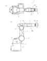
以下、本発明をハンドリング作業用ロボットに適用した場合の第1実施例について図1乃至図6を参照して説明する。図5は、多関節型(6軸)ロボット1を示す(a)平面図、(b)側面図である。このロボット1は、ベース2上に6軸のアームRAを有し、そのアームRAの先端にハンド9が取り付けられている。即ち、前記ベース2上には、第1関節J1を介して第1のアーム3が回転可能に連結されている。この第1のアーム3には、第2関節J2を介して第2のアーム4の下端部が回転可能に連結され、さらに、この第2のアーム4の先端部には、第3関節J3を介して第3のアーム5が回転可能に連結されている。
(First embodiment)
Hereinafter, a first embodiment in which the present invention is applied to a handling robot will be described with reference to FIGS. FIG. 5A is a plan view and FIG. 5B is a side view showing an articulated (6-axis)
この第3のアーム5の先端には第4関節J4を介して第4のアーム6が回転可能に連結され、この第4のアーム6の先端には第5関節J5を介して第5のアーム7が回転可能に連結され、この第5のアーム7には第6関節J6を介して第6のアーム8が回転可能に連結されている。なお、各関節J1〜J6は、例えば夫々に配置されるサーボモータ22(図6参照)により各アーム3〜8を回転駆動するようになっている。また、図4には、アームRAの各軸構成をモデル的に示す。
そして、アーム8には、ハンド9が取り付けられている。この場合、関節J2,J3の角度θ2,θ3の和が180度であれば、関節J4,J5,J6の回動動作は、夫々ハンド9のヨー,ピッチ,ロールに対応することになる。また、ベース2は、レールに沿って移動可能となっており、そのための駆動機構(図示せず)も内蔵している。尚、レールはロボット1の走行軸(冗長軸)となっている。
A
A hand 9 is attached to the
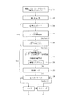
図6は、ロボット1及びその制御系の構成を概略的に示す機能ブロック図である。教示ペンダント11は操作インターフェイス(I/F)であり、操作者は、ハンド9を移動させたい方向に教示ペンダント11の操作キーを操作する。すると、その操作キーの押し度合いに応じた信号(ON/OFF)を、マン・マシン・インターフェイスとしての例えば目標指令生成部13に内蔵される信号入力ボード14に与える。
FIG. 6 is a functional block diagram schematically showing the configuration of the
信号入力ボード14は、操作信号12により与えられる信号をCPU15に出力すると、CPU15は、その操作信号に応じてロボット1のアーム先端(即ち、ハンド9)部分を移動させるための目標速度[m/sec]を換算する。そして、その目標速度を、例えばイーサネット(登録商標)などに対応した通信デバイス16を介してロボット制御用のコントローラ(制御装置)18に送信する。コントローラ18のCPU19は、制御プログラム(コンピュータプログラム)24に従って処理を実行するもので、受信した目標速度に基づいてロボット1の走行軸上の移動量を算出し、また、アームRAの目標位置や姿勢角に関連する目標指令値などを算出する。そして、CPU19は、アーム各軸の指令値[m]を生成すると、制御ボード20を介してロボット1側のモータドライバ21に出力する。
モータドライバ21は、与えられた指令値に応じてアームRAの各軸に配置されているモータ22を駆動する。すると、モータ22による軸変位量はエンコーダ23により検出されて、変位量に応じたパルス信号がモータドライバ21に出力される。
When the
The
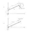
次に、本実施例の作用について図1乃至図3も参照して説明する。図1はコントローラ18のCPU19によって実行されるロボット1の各軸指令値を求める処理の内容を示すフローチャートである。また、図2は、図1の処理に応じて先端位置が移動されるロボット1のアームRAの(ベクトル)モデルである。CPU19は、上述したように目標指令生成部13側より送信された目標速度を取得すると(ステップS1)、その目標速度に基づいて、ロボット1のアームRA先端をサンプリング時間dt内に移動させる目標移動量(ΔX,ΔY,ΔZ)を求める(ステップS2)。
Next, the operation of this embodiment will be described with reference to FIGS. FIG. 1 is a flowchart showing the contents of processing for obtaining each axis command value of the
続いて、CPU19は、アームRA先端の現在位置AP0(X0,Y0,Z0)を取得すると(ステップS3)、走行軸上の移動を行わない状態で(即ち、原点ΣAの座標系において)、現在位置(X0,Y0,Z0)及び目標移動量(ΔX,ΔY,ΔZ)からアームRA先端の目標位置AP1(Xc,Yc,Zc)を算出する(ステップS4,図2(a))。尚、目標位置(Xc,Yc,Zc)は、アームRA先端における姿勢角(ヨー,ピッチ,ロール)の変位がある場合は、同次変換行列の積によって演算される。
Subsequently, when the
次に、CPU19は、アームRAの先端を目標位置(Xc,Yc,Zc)に移動させるための走行軸上の移動量ΔX3を算出すると(ステップS5,図2(b))、その移動量ΔX3だけベース2を移動させた後の新たな座標系(原点ΣB)で表現される目標位置BP1(X1,Y1,Z1)を算出する(ステップS6,図2(c))。そして、目標位置BP1(X1,Y1,Z1),及び姿勢角の目標値(Rx1,Ry1,Rz1)に基づきアームRA各軸の目標位置、移動速度を算出すると(ステップS7)、それらに応じた各軸毎の指令値を出力する(ステップS8)。それから、ステップS1に戻る。即ち、以上の処理は走行軸協調制御である。
Next, when the
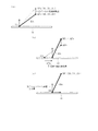
次に、ステップS5における走行軸上の移動量ΔX3の算出について、図3を参照して説明する。図3(a)はアームRAのxz座標系(垂直面)であり、(b)は同xy座標系(水平面)である。図3(a)において、座標原点ΣBから関節J2までの高さをd2,関節J2がz軸に対してなす角度をθ2,関節J2から関節J3までの距離(=アーム4)をL2,関節J3がアーム4に対してなす角度をθ3,関節J3から関節J5までの距離(=アーム5)をL3としている。尚、図5に示すようにハンド9はアーム5の先端、即ち関節J5の位置に取り付けられているので、関節J5がアームRAの先端となる。
Next, calculation of the movement amount ΔX3 on the travel axis in step S5 will be described with reference to FIG. 3A shows the xz coordinate system (vertical plane) of the arm RA, and FIG. 3B shows the xy coordinate system (horizontal plane). In FIG. 3A, the height from the coordinate origin ΣB to the joint J2 is d2, the angle formed by the joint J2 with respect to the z axis is θ2, the distance from the joint J2 to the joint J3 (= arm 4) is L2, the joint The angle formed by J3 with respect to
また、図3(b)において、関節J1がx軸に対してなす角度をθ2としている。この場合、x軸が走行軸に一致している。そして、図3は、原点ΣAから走行軸上をΔX3移動させた原点ΣBの座標系であり、従って、アームRAの先端は目標位置(Xc,Yc,Zc)を示している。
すると、目標位置(Xc,Yc,Zc)の各座標は、原点ΣAを基準として以下のように表される。
Xc={L2・sinθ2+L3・sin(θ2+θ3)}cosθ1+ΔX3
・・・(1)
Yc={L2・sinθ2+L3・sin(θ2+θ3)}sinθ1・・・(2)
Zc= L2・cosθ2+d2−L3・cos(π−θ2−θ3)
= L2・cosθ2+d2+L3・cos(θ2+θ3) ・・・(3)
ここで、移動量ΔX3は、サンプリング時間毎にベース2が移動する走行軸上の距離であり、目標位置(Xc,Yc,Zc)が決まると、d2,L2,L3,θ1〜θ3の6つの自由度を設定することで(1)〜(3)式に基づいて移動量ΔX3を求めることになる。尚、d2,L2,L3は固定値である。また、(θ2+θ3)は、アームRAの先端に取り付けられたハンド9の姿勢制御軸であるJ4〜J6の基準位置を一定に保つため、不変とすることを拘束条件とする。
In FIG. 3B, an angle formed by the joint J1 with respect to the x-axis is θ2. In this case, the x axis coincides with the travel axis. FIG. 3 shows a coordinate system of the origin ΣB moved by ΔX3 on the travel axis from the origin ΣA. Therefore, the tip of the arm RA indicates the target position (Xc, Yc, Zc).
Then, each coordinate of the target position (Xc, Yc, Zc) is expressed as follows using the origin ΣA as a reference.
Xc = {L2 · sin θ2 + L3 · sin (θ2 + θ3)} cos θ1 + ΔX3
... (1)
Yc = {
Zc =
= L2 · cos θ2 + d2 + L3 · cos (θ2 + θ3) (3)
Here, the movement amount ΔX3 is a distance on the travel axis at which the
(1)式より、
Xc−ΔX3={L2・sinθ2+L3・sin(θ2+θ3)}cosθ1
・・・(4)
ここで、α=L2・sinθ2+L3・sin(θ2+θ3) とすると、
Xc−ΔX3=α・cosθ1 ・・・(5)
Yc=α・sinθ1 ・・・(6)
よって、
(Xc−ΔX3)2+Yc2=α2 ・・・(7)
また、(3)式より、
L2・cosθ2=Zc−d2−L3・cos(θ2+θ3) ・・・(8)
(7)式より、
L2・sinθ2+L3・sin(θ2+θ3)
=±{(Xc−ΔX3)2+Yc2}1/2
L2・sinθ2=−L3・sin(θ2+θ3)
±{(Xc−ΔX3)2+Yc2}1/2 ・・・(9)
(8)、(9)式より、
L22(cos2θ2+sin2θ2)
={Zc−d2−L3・cos(θ2+θ3)}2
+[−L3・sin(θ2+θ3)±{(Xc−ΔX3)2+Yc2}1/2]2
ここで、β=Zc−d2−L3・cos(θ2+θ3)
γ=L3・sin(θ2+θ3) とすると、上記拘束条件により
(θ2+θ3)=const.であるから、β及びγは固定値となる。
From equation (1)
Xc−ΔX3 = {L2 · sin θ2 + L3 · sin (θ2 + θ3)} cos θ1
... (4)
Here, if α = L2 · sin θ2 + L3 · sin (θ2 + θ3),
Xc−ΔX3 = α · cos θ1 (5)
Yc = α · sin θ1 (6)
Therefore,
(Xc−ΔX3) 2 + Yc 2 = α 2 (7)
Also, from equation (3)
L2 · cos θ2 = Zc−d2−L3 · cos (θ2 + θ3) (8)
From equation (7)
L2 · sin θ2 + L3 · sin (θ2 + θ3)
= ± {(Xc−ΔX3) 2 + Yc 2 } 1/2
L2 · sin θ2 = −L3 · sin (θ2 + θ3)
± {(Xc−ΔX3) 2 + Yc 2 } 1/2 (9)
From equations (8) and (9)
L2 2 (cos 2 θ2 + sin 2 θ2)
= {Zc-d2-L3 · cos (θ2 + θ3)} 2
+ [− L3 · sin (θ2 + θ3) ± {(Xc−ΔX3) 2 + Yc 2 } 1/2 ] 2
Here, β = Zc−d2−L3 · cos (θ2 + θ3)
If γ = L3 · sin (θ2 + θ3), (θ2 + θ3) = const. Therefore, β and γ are fixed values.
L22=β2+{−γ±{(Xc−ΔX3)2+Yc2}1/2}2
−γ±{(Xc−ΔX3)2+Yc2}1/2=±(L22−β2)1/2
±{(Xc−ΔX3)2+Yc2}1/2=γ±(L22−β2)1/2
(Xc−ΔX3)2+Yc2={γ±(L22−β2)1/2}2
ΔX3=Xc±[{γ±(L22−β2)1/2}2−Yc2]1/2 ・・・(10)
以上のようにΔX3が求められる。ここで、符号の正負の組み合わせにより(10)式からは以下の4つの解が得られる。
ΔX31=Xc+[{γ+(L22−β2)1/2}2−Yc2]1/2
ΔX32=Xc+[{γ−(L22−β2)1/2}2−Yc2]1/2
ΔX33=Xc−[{γ+(L22−β2)1/2}2−Yc2]1/2
ΔX34=Xc−[{γ−(L22−β2)1/2}2−Yc2]1/2
これら4つの内、絶対値が最小となるものをΔX3として選択する。
L2 2 = β 2 + {− γ ± {(Xc−ΔX3) 2 + Yc 2 } 1/2 } 2
−γ ± {(Xc−ΔX3) 2 + Yc 2 } 1/2 = ± (L2 2 −β 2 ) 1/2
± {(Xc−ΔX3) 2 + Yc 2 } 1/2 = γ ± (L2 2 −β 2 ) 1/2
(Xc−ΔX3) 2 + Yc 2 = {γ ± (L2 2 −β 2 ) 1/2 } 2
ΔX3 = Xc ± [{γ ± (L2 2 −β 2 ) 1/2 } 2 −Yc 2 ] 1/2 (10)
As described above, ΔX3 is obtained. Here, the following four solutions can be obtained from the equation (10) by the combination of positive and negative signs.
ΔX31 = Xc + [{γ + (L2 2 −β 2 ) 1/2 } 2 −Yc 2 ] 1/2
ΔX32 = Xc + [{γ− (L2 2 −β 2 ) 1/2 } 2 −Yc 2 ] 1/2
ΔX33 = Xc − [{γ + (L2 2 −β 2 ) 1/2 } 2 −Yc 2 ] 1/2
ΔX34 = Xc − [{γ− (L2 2 −β 2 ) 1/2 } 2 −Yc 2 ] 1/2
Among these four, the one having the smallest absolute value is selected as ΔX3.
以上のように本実施例によれば、ロボット1の制御を行うコントローラ18は、垂直多関節型で6軸のアームRAの先端について、現在位置(X0,Y0,Z0)と所定時間後の目標移動量(ΔX,ΔY,ΔZ)とに基づいて決定される目標位置(Xc,Yc,Zc)に対し、その時点でアームRAが保持している第2関節角度θ2と第3関節角度θ3との和が一定となることを拘束条件として、アームRAの先端を目標位置に移動させるために必要な走行軸上における所定時間当たりの移動量ΔX3を計算するようにした。
従って、走行軸上の移動量ΔX3については指定を行う必要がなくなり、アームRAの先端を目標位置に到達させるためのロボット制御、若しくはそのためのティーチングをより簡単に行うことができる。
As described above, according to the present embodiment, the
Therefore, it is not necessary to specify the movement amount ΔX3 on the travel axis, and robot control for reaching the tip of the arm RA to the target position or teaching for that can be performed more easily.
(第2実施例)
図8は本発明の第2実施例を示すものであり、第1実施例と同一部分には同一符号を付して説明を省略し、以下異なる部分についてのみ説明する。第2実施例の構成は基本的に第1実施例と同様であり、コントローラ18のCPU19によって実行される制御内容が第1実施例と若干異なっている。
即ち、図8に示すように、CPU19は、ステップS7において、各軸の目標位置及び目標速度を算出すると、走行軸に関する目標速度ΔV3(=ΔX3/dt:dtは、サンプリング時間)を上限速度Vmaxと比較してΔV3>Vmaxか否かを判断する(ステップS11)。そして、ΔV3≦Vmaxであれば(「NO」)そのままステップS8に移行する。
(Second embodiment)
FIG. 8 shows a second embodiment of the present invention. The same parts as those of the first embodiment are denoted by the same reference numerals and the description thereof is omitted. Only different parts will be described below. The configuration of the second embodiment is basically the same as that of the first embodiment, and the control content executed by the
That is, as shown in FIG. 8, when the
一方、ステップS11においてΔV3>Vmaxであれば(「YES」)、CPU19は両者の差dV3(=Vmax−ΔV3)を演算する(ステップS12)。そして、求めた差dV3に、サンプリング時間dtをかけた距離をx座標値X1に加える(ステップS13)。但し、この場合、ステップS12で求めた差dV3の符号は負であるから、実質的には、X1−|dV3|・dtである。それから、ステップS8に移行する。この場合、走行軸上の移動速度は、上限速度Vmaxで規制されることになる。
On the other hand, if ΔV3> Vmax in step S11 (“YES”), the
即ち、拘束条件(θ2+θ3=一定)を与えて求めた目標移動量ΔX3だけ、アームRAの先端を所定時間dt内に移動させようとすると、ロボット1の動作条件として設定されている上限速度Vmaxを超えてしまう場合が想定される。そして、上限速度Vmaxを超える速度でアームRAを動作させると、ロボット1の機構に過大な負担をかけてしまうおそれがある。従って、そのようなケースでは、上限速度Vmaxを超えない範囲で移動させることを優先して、上記のように拘束条件を解除して走行軸上の移動距離を短縮するように修正する。
That is, if the tip of the arm RA is moved within the predetermined time dt by the target movement amount ΔX3 obtained by giving the constraint condition (θ2 + θ3 = constant), the upper limit speed Vmax set as the operation condition of the
以上のように第2実施例によれば、CPU19は、走行軸上における所定時間dt当たりの移動量ΔX3に基づいて求めた移動速度ΔV3が上限速度Vmaxを超える場合には、拘束条件を解除して移動速度ΔV3を上限速度Vmaxに置き換え、両速度の差dV3に応じた移動量を走行軸上の座標値X1より減じて目標位置を修正するので、ロボット1の機構に過大な負担をかける事態を回避することができる。
As described above, according to the second embodiment, the
本発明は上記し又は図面に記載した実施例にのみ限定されるものではなく、次のような変形が可能である。
走行軸上の移動量について作業者により直接入力が行われた場合は、本発明の手法を用いることなく、前記入力操作量に応じてロボット1をレール上で移動させれば良い。
オンライン,オフラインティーチングの場合も、同様に適用が可能である。
ハンドリング作業用に限らず、例えば組立てや塗装,溶接などの広範囲での作業を必要とするため、走行軸により可動範囲を広げるようにしたものにも適用することができる。また、生産設備のセル内で稼動するロボットにおいて、アーム長を抑えつつ可動範囲を広げるため走行軸を用いるものに適用することができる。
The present invention is not limited to the embodiments described above or shown in the drawings, and the following modifications are possible.
When the operator directly inputs the movement amount on the travel axis, the
The same applies to online and offline teaching.
The present invention is not limited to handling operations, but requires a wide range of operations such as assembly, painting, and welding, and therefore can be applied to ones in which the movable range is expanded by a traveling shaft. Further, the present invention can be applied to a robot that operates in a cell of a production facility and that uses a travel axis to extend the movable range while suppressing the arm length.
図面中、1はロボット、9はハンド、18はコントローラ(制御装置)、19はCPU、24は制御プログラム(コンピュータプログラム)、RAはアームを示す。 In the drawings, 1 is a robot, 9 is a hand, 18 is a controller (control device), 19 is a CPU, 24 is a control program (computer program), and RA is an arm.
Claims (6)
前記アームの先端について、現在位置と、所定時間後の目標移動量とに基づいて決定される目標位置に対し、
その時点で前記アームが保持している第2関節角度θ2と第3関節角度θ3との和が一定となることを拘束条件として、前記アームの先端を前記目標位置に移動させるために必要な、前記走行軸上における前記所定時間当たりの移動量を計算することを特徴とするロボット制御装置。 In a control device for controlling a robot having a traveling axis as a redundant axis and a vertical articulated 6-axis arm,
For the tip of the arm, with respect to the target position determined based on the current position and the target movement amount after a predetermined time,
Necessary for moving the tip of the arm to the target position on the condition that the sum of the second joint angle θ2 and the third joint angle θ3 held by the arm at that time is constant, A robot control apparatus for calculating a movement amount per predetermined time on the travel axis.
前記アームの先端について、現在位置と、所定時間後の目標移動量とに基づいて決定される目標位置に対し、
その時点で前記アームが保持している第2関節角度θ2と第3関節角度θ3との和が一定となることを拘束条件として、前記アームの先端を前記目標位置に移動させるために必要な、前記走行軸上における前記所定時間当たりの移動量を計算することを特徴とするロボット制御方法。 In a control method for controlling a robot having a traveling axis as a redundant axis and a vertical articulated 6-axis arm,
For the tip of the arm, with respect to the target position determined based on the current position and the target movement amount after a predetermined time,
Necessary for moving the tip of the arm to the target position on the condition that the sum of the second joint angle θ2 and the third joint angle θ3 held by the arm at that time is constant, A robot control method, comprising: calculating a movement amount per predetermined time on the travel axis.
前記移動速度が上限速度を超える場合には、上記拘束条件を解除して前記移動速度を上限速度に置き換え、
両速度の差に応じた移動量を前記走行軸上の座標値より減じて前記目標位置を修正することを特徴とする請求項3記載のロボット制御方法。 Obtaining the moving speed based on the moving amount per predetermined time on the travel axis,
When the movement speed exceeds the upper limit speed, the restriction condition is canceled and the movement speed is replaced with the upper limit speed.
4. The robot control method according to claim 3, wherein the target position is corrected by subtracting a movement amount corresponding to a difference between both speeds from a coordinate value on the travel axis.
前記アームの先端について、現在位置と、所定時間後の目標移動量とに基づいて決定される目標位置に対し、
その時点で前記アームが保持している第2関節角度θ2と第3関節角度θ3との和が一定となることを拘束条件として、前記アームの先端を前記目標位置に移動させるために必要な、前記走行軸上における前記所定時間当たりの移動量を計算させることを特徴とするコンピュータプログラム。 In a program executed by a computer constituting a control device that controls a robot having a traveling axis as a redundant axis and a vertical articulated 6-axis arm,
For the tip of the arm, with respect to the target position determined based on the current position and the target movement amount after a predetermined time,
Necessary for moving the tip of the arm to the target position on the condition that the sum of the second joint angle θ2 and the third joint angle θ3 held by the arm at that time is constant, A computer program for calculating a movement amount per predetermined time on the travel axis.
前記移動速度が上限速度を超える場合には、上記拘束条件を解除して前記移動速度を上限速度に置き換えさせ、
両速度の差に応じた移動量を前記走行軸上の座標値より減じて前記目標位置を修正させることを特徴とする請求項5記載のコンピュータプログラム。
Based on the amount of movement per predetermined time on the travel axis, to determine the movement speed,
When the movement speed exceeds the upper limit speed, the restriction condition is canceled and the movement speed is replaced with the upper limit speed.
6. The computer program according to claim 5, wherein the target position is corrected by subtracting a movement amount corresponding to a difference between both speeds from a coordinate value on the travel axis.
Priority Applications (1)
| Application Number | Priority Date | Filing Date | Title |
|---|---|---|---|
| JP2005075026A JP4396553B2 (en) | 2005-03-16 | 2005-03-16 | Robot controller, computer program |
Applications Claiming Priority (1)
| Application Number | Priority Date | Filing Date | Title |
|---|---|---|---|
| JP2005075026A JP4396553B2 (en) | 2005-03-16 | 2005-03-16 | Robot controller, computer program |
Publications (2)
| Publication Number | Publication Date |
|---|---|
| JP2006260010A true JP2006260010A (en) | 2006-09-28 |
| JP4396553B2 JP4396553B2 (en) | 2010-01-13 |
Family
ID=37099214
Family Applications (1)
| Application Number | Title | Priority Date | Filing Date |
|---|---|---|---|
| JP2005075026A Expired - Fee Related JP4396553B2 (en) | 2005-03-16 | 2005-03-16 | Robot controller, computer program |
Country Status (1)
| Country | Link |
|---|---|
| JP (1) | JP4396553B2 (en) |
Cited By (6)
| Publication number | Priority date | Publication date | Assignee | Title |
|---|---|---|---|---|
| JP2010214544A (en) * | 2009-03-17 | 2010-09-30 | Toshiba Corp | Track generation system of moving manipulator |
| JP2014042953A (en) * | 2012-08-27 | 2014-03-13 | Amada Co Ltd | Apparatus and method for controlling robot |
| JP2014151385A (en) * | 2013-02-07 | 2014-08-25 | Amada Co Ltd | Robot control device, and robot control method |
| JP2015107657A (en) * | 2015-02-03 | 2015-06-11 | アピックヤマダ株式会社 | Resin molding apparatus |
| JP2017035756A (en) * | 2015-08-10 | 2017-02-16 | ファナック株式会社 | Robot control device suppressing vibration of tool tip end of robot having travel shaft |
| WO2022163743A1 (en) * | 2021-01-29 | 2022-08-04 | ファナック株式会社 | Numerical control apparatus and numerical control system |
Families Citing this family (1)
| Publication number | Priority date | Publication date | Assignee | Title |
|---|---|---|---|---|
| CN108480871A (en) * | 2018-03-13 | 2018-09-04 | 武汉逸飞激光设备有限公司 | A kind of battery modules welding method and system |
-
2005
- 2005-03-16 JP JP2005075026A patent/JP4396553B2/en not_active Expired - Fee Related
Cited By (11)
| Publication number | Priority date | Publication date | Assignee | Title |
|---|---|---|---|---|
| JP2010214544A (en) * | 2009-03-17 | 2010-09-30 | Toshiba Corp | Track generation system of moving manipulator |
| JP2014042953A (en) * | 2012-08-27 | 2014-03-13 | Amada Co Ltd | Apparatus and method for controlling robot |
| JP2014151385A (en) * | 2013-02-07 | 2014-08-25 | Amada Co Ltd | Robot control device, and robot control method |
| JP2015107657A (en) * | 2015-02-03 | 2015-06-11 | アピックヤマダ株式会社 | Resin molding apparatus |
| JP2017035756A (en) * | 2015-08-10 | 2017-02-16 | ファナック株式会社 | Robot control device suppressing vibration of tool tip end of robot having travel shaft |
| CN106444624A (en) * | 2015-08-10 | 2017-02-22 | 发那科株式会社 | Robot controller inhibiting shaking of tool tip in robot equipped with travel axis |
| US9827673B2 (en) | 2015-08-10 | 2017-11-28 | Fanuc Corporation | Robot controller inhibiting shaking of tool tip in robot equipped with travel axis |
| CN106444624B (en) * | 2015-08-10 | 2018-06-29 | 发那科株式会社 | Inhibit the robot controller of the front tool vibration of the robot with shifting axle |
| WO2022163743A1 (en) * | 2021-01-29 | 2022-08-04 | ファナック株式会社 | Numerical control apparatus and numerical control system |
| JP7177301B1 (en) * | 2021-01-29 | 2022-11-22 | ファナック株式会社 | Numerical controller and numerical control system |
| TWI826893B (en) * | 2021-01-29 | 2023-12-21 | 日商發那科股份有限公司 | Numerical control device and numerical control system |
Also Published As
| Publication number | Publication date |
|---|---|
| JP4396553B2 (en) | 2010-01-13 |
Similar Documents
| Publication | Publication Date | Title |
|---|---|---|
| JP6706489B2 (en) | Robot direct teaching method | |
| JP6924145B2 (en) | Robot teaching method and robot arm control device | |
| KR940003204B1 (en) | Control robot | |
| JP4396553B2 (en) | Robot controller, computer program | |
| JP4917252B2 (en) | Arc welding equipment | |
| Bolmsjö et al. | Robotic arc welding–trends and developments for higher autonomy | |
| KR101498835B1 (en) | Control method for seven-shaft multi-joint robot, control program, and robot control device | |
| JP2015202534A (en) | Robot control device and robot system for robot moved according to input power | |
| JP2010167515A (en) | Multi-axial robot and speed controller for the same | |
| JP2007319970A (en) | Method of controlling location/position of tool of industrial robot, and control system | |
| JP2010231575A (en) | Device and method for instruction of off-line of robot, and robot system | |
| CN114952838B (en) | Mechanical arm joint track planning method based on terminal measurement feedback | |
| WO2019107208A1 (en) | Method for controlling operation of working machine | |
| JP2013223895A (en) | Robot control method and robot control device | |
| WO2021241512A1 (en) | Control device, robot system, and control method for causing robot to execute work on workpiece | |
| US11654562B2 (en) | Apparatus, robot control device, robot system, and method of setting robot coordinate system | |
| JP2014180726A (en) | Compensating device for spring constant of multi-joint robot | |
| JPH11191005A (en) | Robot control unit | |
| Juan et al. | Analysis and simulation of a 6R robot in virtual reality | |
| JP7424097B2 (en) | Robot control device and robot control method | |
| JP7502439B2 (en) | Robot Control Device | |
| US20210299869A1 (en) | Teaching Method | |
| JP2013223896A (en) | Robot control method and robot control device | |
| JP7543160B2 (en) | Spring constant correction device, method and program | |
| JP2005230952A (en) | Control method and control device |
Legal Events
| Date | Code | Title | Description |
|---|---|---|---|
| A621 | Written request for application examination |
Free format text: JAPANESE INTERMEDIATE CODE: A621 Effective date: 20070316 |
|
| A131 | Notification of reasons for refusal |
Free format text: JAPANESE INTERMEDIATE CODE: A131 Effective date: 20090526 |
|
| A977 | Report on retrieval |
Free format text: JAPANESE INTERMEDIATE CODE: A971007 Effective date: 20090528 |
|
| A521 | Written amendment |
Free format text: JAPANESE INTERMEDIATE CODE: A523 Effective date: 20090707 |
|
| TRDD | Decision of grant or rejection written | ||
| A01 | Written decision to grant a patent or to grant a registration (utility model) |
Free format text: JAPANESE INTERMEDIATE CODE: A01 Effective date: 20090929 |
|
| A01 | Written decision to grant a patent or to grant a registration (utility model) |
Free format text: JAPANESE INTERMEDIATE CODE: A01 |
|
| A61 | First payment of annual fees (during grant procedure) |
Free format text: JAPANESE INTERMEDIATE CODE: A61 Effective date: 20091012 |
|
| FPAY | Renewal fee payment (event date is renewal date of database) |
Free format text: PAYMENT UNTIL: 20121030 Year of fee payment: 3 |
|
| R150 | Certificate of patent or registration of utility model |
Ref document number: 4396553 Country of ref document: JP Free format text: JAPANESE INTERMEDIATE CODE: R150 Free format text: JAPANESE INTERMEDIATE CODE: R150 |
|
| S531 | Written request for registration of change of domicile |
Free format text: JAPANESE INTERMEDIATE CODE: R313531 |
|
| FPAY | Renewal fee payment (event date is renewal date of database) |
Free format text: PAYMENT UNTIL: 20121030 Year of fee payment: 3 |
|
| R350 | Written notification of registration of transfer |
Free format text: JAPANESE INTERMEDIATE CODE: R350 |
|
| FPAY | Renewal fee payment (event date is renewal date of database) |
Free format text: PAYMENT UNTIL: 20121030 Year of fee payment: 3 |
|
| FPAY | Renewal fee payment (event date is renewal date of database) |
Free format text: PAYMENT UNTIL: 20121030 Year of fee payment: 3 |
|
| FPAY | Renewal fee payment (event date is renewal date of database) |
Free format text: PAYMENT UNTIL: 20131030 Year of fee payment: 4 |
|
| R250 | Receipt of annual fees |
Free format text: JAPANESE INTERMEDIATE CODE: R250 |
|
| R250 | Receipt of annual fees |
Free format text: JAPANESE INTERMEDIATE CODE: R250 |
|
| R250 | Receipt of annual fees |
Free format text: JAPANESE INTERMEDIATE CODE: R250 |
|
| R250 | Receipt of annual fees |
Free format text: JAPANESE INTERMEDIATE CODE: R250 |
|
| R250 | Receipt of annual fees |
Free format text: JAPANESE INTERMEDIATE CODE: R250 |
|
| R250 | Receipt of annual fees |
Free format text: JAPANESE INTERMEDIATE CODE: R250 |
|
| R250 | Receipt of annual fees |
Free format text: JAPANESE INTERMEDIATE CODE: R250 |
|
| R250 | Receipt of annual fees |
Free format text: JAPANESE INTERMEDIATE CODE: R250 |
|
| LAPS | Cancellation because of no payment of annual fees |