JP2006240468A - Steering device, and coaxial coupling - Google Patents
Steering device, and coaxial coupling Download PDFInfo
- Publication number
- JP2006240468A JP2006240468A JP2005058369A JP2005058369A JP2006240468A JP 2006240468 A JP2006240468 A JP 2006240468A JP 2005058369 A JP2005058369 A JP 2005058369A JP 2005058369 A JP2005058369 A JP 2005058369A JP 2006240468 A JP2006240468 A JP 2006240468A
- Authority
- JP
- Japan
- Prior art keywords
- shaft
- steering
- inner peripheral
- rotation
- outer peripheral
- Prior art date
- Legal status (The legal status is an assumption and is not a legal conclusion. Google has not performed a legal analysis and makes no representation as to the accuracy of the status listed.)
- Pending
Links
Images


Landscapes
- Steering-Linkage Mechanisms And Four-Wheel Steering (AREA)
- Power Steering Mechanism (AREA)
- Steering Controls (AREA)
Abstract
Description
本発明は、ステアリングホイールの操舵角に対する転舵輪の転舵角の比を可変制御する伝達比可変機構を備えたステアリング装置、および同軸カップリングに関するものである。 The present invention relates to a steering device including a transmission ratio variable mechanism that variably controls a ratio of a turning angle of a steered wheel to a steering angle of a steering wheel, and a coaxial coupling.
特許文献1には、弾性継手2、及びこの弾性継手2を介してステアリングホイールの操舵角が伝達されるアクチュエータ1を備えた伝達比可変操舵装置が記載されている。弾性継手2は、第1ヨーク20、円盤状のゴム製継手本体22、第2ヨーク24及びダンパ25から構成され、第1ヨーク20はフックスジョイント4の出力側となっている。第1ヨーク20とダンパ25とは2本の第1ボルト21によりゴム製継手本体22に共締めされている。第2ヨーク24は、2本の第2ボルト23によりゴム製継手本体22に固定されている。ゴム製継手本体22の軸直角断面において、2本の第1ボルト21の中心線を結ぶ線は2本の第2ボルト23の中心線を結ぶ線と直交している。
Patent Document 1 describes a transmission ratio variable steering apparatus including an elastic joint 2 and an actuator 1 through which the steering angle of the steering wheel is transmitted via the elastic joint 2. The elastic joint 2 includes a
アクチュエータ1は、入力軸14と、モータ12と、ギヤ機構13と、出力軸15とから構成されている。入力軸14は第2ヨーク24と一体に形成されてハウジング10に回転可能に支承されている。モータ12はハウジング10内に固定され、電子制御ユニットからの指令によりモータ軸が回転される。モータ軸の回転はギヤ機構13により減速され、ハウジング10に支承された出力軸15を回転駆動する。出力軸15の回転は転舵系に転舵角として転舵輪に伝達される。
特許文献1に記載された弾性継手は、円盤状のゴム製継手本体22を介して第1ヨークと第2ヨークとの間で回転を伝達する。また、ゴム製継手本体22は、転舵輪を介して伝達される路面の起伏に起因する振動および音がステアリングホイールに伝播されないように吸収している。
The elastic joint described in Patent Document 1 transmits rotation between the first yoke and the second yoke via a disk-shaped
このように、特許文献1に記載された弾性継手は、振動および音を遮断するとともにステアリングホイールの回転をロスなく転舵輪に伝達する必要があった。このため、従来のゴム製継手本体は、振動および音を遮断するため、軸線方向および径方向では剛性を小さく、ステアリングホイールの回転をロスなく転舵輪に伝達するために捩れ方向では剛性を大きくする必要があり、適正な剛性とするには、内部にワイヤ等の補強材を入れて調整しなければならなかった。さらに、特許文献1のように弾性継手と転舵系の間に伝達比可変機構を備えるステアリング装置では、ゴム製継手本体が剛性不足の場合、伝達比可変機構の重量によって撓み、第1ヨークと第2ヨークの間で回転中心にずれが発生し、伝達比可変機構が振れ回りする怖れがあった。このため、伝達比可変機構を備えるステアリング装置では、より正確なゴム製継手本体の剛性の調整が必要であった。 As described above, the elastic joint described in Patent Document 1 needs to block vibration and sound and transmit the rotation of the steering wheel to the steered wheels without loss. For this reason, the conventional rubber joint body has low rigidity in the axial direction and radial direction in order to cut off vibration and sound, and has high rigidity in the torsion direction in order to transmit the rotation of the steering wheel to the steered wheels without loss. In order to obtain the proper rigidity, a reinforcing material such as a wire had to be put inside and adjusted. Furthermore, in a steering device having a transmission ratio variable mechanism between an elastic joint and a steering system as in Patent Document 1, when the rubber joint body is insufficient in rigidity, the rubber is bent by the weight of the transmission ratio variable mechanism, There was a fear that the transmission center variable mechanism swings due to a shift in the center of rotation between the second yokes. For this reason, in a steering device provided with a transmission ratio variable mechanism, it is necessary to adjust the rigidity of the rubber joint body more accurately.
本発明は、かかる要望を満たすためになされたもので、従来と比較して簡単に振動および音を遮断が可能であるとともに、ステアリングホイールの回転をロスなく転舵輪に伝達できるステアリング装置の構成を提供することを目的とする。 The present invention has been made to satisfy such a demand, and has a configuration of a steering device that can easily cut off vibrations and sounds as compared with the prior art and can transmit the rotation of the steering wheel to the steered wheels without loss. The purpose is to provide.
上記課題を解決するために、請求項1に係る発明の構成上の特徴は、ステアリングホイールの回転が伝達される操舵軸と、転舵輪に転舵角を付与するステアリングギヤに回転を伝達する転舵軸と、操舵軸と転舵軸の間に配置され、ステアリングホイールの操舵角に対する転舵輪の転舵角の比を変化させて伝達する伝達比可変機構と、から構成される回転伝達経路を備えたステアリング装置において、回転伝達経路の途中にステアリングホイールとステアリングギヤとの軸線方向の相対移動を許容する軸動機構を設け、操舵軸および伝達比可変機構の一方に結合され中空穴が穿設された外周軸と、操舵軸および伝達比可変機構の他方に結合され中空穴に挿入される内周軸と、内周軸の外周面と中空穴の内周面の間に介在され外周軸と内周軸を結合する環状の弾性部材を備えた同軸カップリングを回転伝達経路のステアリングホイールと伝達比可変機構との間に設けたことである。 In order to solve the above-mentioned problem, the structural feature of the invention according to claim 1 is that the rotation is transmitted to the steering shaft to which the rotation of the steering wheel is transmitted and the steering gear that gives the steered wheel a turning angle. A rotation transmission path comprising a rudder shaft, and a transmission ratio variable mechanism that is disposed between the steering shaft and the steered shaft and transmits the steered wheel by changing the ratio of the steered angle of the steered wheel to the steered angle of the steering wheel. In the steering apparatus provided, an axial movement mechanism that allows relative movement of the steering wheel and the steering gear in the axial direction is provided in the middle of the rotation transmission path, and a hollow hole is formed by being coupled to one of the steering shaft and the transmission ratio variable mechanism. An outer peripheral shaft, an inner peripheral shaft coupled to the other of the steering shaft and the transmission ratio variable mechanism and inserted into the hollow hole, and an outer peripheral shaft interposed between the outer peripheral surface of the inner peripheral shaft and the inner peripheral surface of the hollow hole, Connect the inner shaft Coaxial coupling with an annular elastic member which is that provided between the steering wheel rotation transmission path and the transmission ratio variable mechanism.
請求項2に係る発明の構成上の特徴は、請求項1において、軸動機構は、軸線方向に摺動穴が穿設された収納軸と、摺動穴に相対回転を規制され軸線方向に摺動可能に嵌合する摺動部が形成された収縮軸とから成り、車両衝突時のステアリングギヤ側の軸動がステアリングホイール側に伝達しないように、収納軸と収縮軸とが軸線方向に相対的に収縮するコラプス機能を備えたことである。 The structural feature of the invention according to claim 2 is that, in claim 1, the axial movement mechanism includes: a storage shaft having a sliding hole in the axial direction; and a relative rotation restricted by the sliding hole in the axial direction. The storage shaft and the contraction shaft are arranged in the axial direction so that the axial movement on the steering gear side in the event of a vehicle collision is not transmitted to the steering wheel side. It has a collapse function that contracts relatively.
請求項3に係る発明の構成上の特徴は、請求項2において、同軸カップリングの外周軸および内周軸の一方を伝達比可変機構の入力軸と結合し、外周軸および内周軸の他方を軸動機構の収納軸および収縮軸の一方と結合し、収納軸および収縮軸の他方を操舵軸に連結したことである。 The structural feature of the invention according to claim 3 is that, in claim 2, one of the outer peripheral shaft and the inner peripheral shaft of the coaxial coupling is coupled to the input shaft of the transmission ratio variable mechanism, and the other of the outer peripheral shaft and the inner peripheral shaft. Is coupled to one of the storage shaft and the contraction shaft of the axial movement mechanism, and the other of the storage shaft and the contraction shaft is connected to the steering shaft.
請求項4に係る発明の構成上の特徴は、請求項2において、同軸カップリングの外周軸および内周軸の一方を伝達比可変機構の入力軸と結合し、外周軸および内周軸の他方を操舵軸と連結し、伝達比可変機構の出力軸を軸動機構の収納軸とし、収縮軸を転舵軸に連結したことである。 The structural feature of the invention according to claim 4 is that, in claim 2, one of the outer peripheral shaft and the inner peripheral shaft of the coaxial coupling is coupled to the input shaft of the transmission ratio variable mechanism, and the other of the outer peripheral shaft and the inner peripheral shaft. Is connected to the steering shaft, the output shaft of the transmission ratio variable mechanism is used as the storage shaft of the axial movement mechanism, and the contraction shaft is connected to the steered shaft.
請求項5に係る発明の構成上の特徴は、請求項3において、同軸カップリングの外周軸および内周軸の一方を伝達比可変機構の入力軸と結合し、外周軸および内周軸の他方を軸動機構の収納軸と結合し、収納軸の摺動穴と同軸に内周軸に貫通穴を穿設し、収縮軸の摺動部が摺動穴および貫通穴を通過して没入可能な中空の退避空間を伝達比可変機構内に形成したことである。 The structural feature of the invention according to claim 5 is that, in claim 3, one of the outer peripheral shaft and the inner peripheral shaft of the coaxial coupling is coupled to the input shaft of the transmission ratio variable mechanism, and the other of the outer peripheral shaft and the inner peripheral shaft. Is coupled with the storage shaft of the shaft movement mechanism, and a through hole is drilled in the inner peripheral shaft coaxially with the slide hole of the storage shaft, and the sliding portion of the contraction shaft can be inserted through the slide hole and the through hole. This is that a hollow retreat space is formed in the transmission ratio variable mechanism.
請求項6に係る発明の構成上の特徴は、請求項4において、軸動機構の収納軸とされた出力軸に形成された摺動穴と連通し、収縮軸の摺動部が摺動穴を通過して没入可能な中空の退避空間を伝達比可変機構に形成したことである。 The structural feature of the invention according to claim 6 is that, in claim 4, the sliding portion of the contraction shaft communicates with the sliding hole formed in the output shaft that is the storage shaft of the axial movement mechanism. A hollow evacuation space that can be immersed through is formed in the transmission ratio variable mechanism.
請求項7に係る発明の構成上の特徴は、請求項5または請求項6において、軸動機構の収縮軸に形成された摺動部を伝達比可変機構の退避空間側に摺動穴から突出させ、突出した摺動部端に摺動穴との間の軸動を規制して摺動穴から収縮軸が脱落することを防止する抜け止め部を形成したことである。 The structural feature of the invention according to claim 7 is that in claim 5 or claim 6, the sliding portion formed on the contraction shaft of the axial movement mechanism protrudes from the sliding hole to the retreat space side of the transmission ratio variable mechanism. In addition, a slip-off preventing portion that prevents the contraction shaft from falling out of the sliding hole by restricting the axial movement between the sliding hole at the protruding sliding portion end is formed.
請求項8に係る発明の構成上の特徴は、請求項7において、抜け止め部に先端に向かって次第に径が小さくなるテーパ部を形成したことである。 The structural feature of the invention according to claim 8 is that, in claim 7, a taper portion whose diameter gradually decreases toward the tip is formed in the retaining portion.
請求項9に係る発明の構成上の特徴は、請求項1ないし請求項7のいずれか一項において、伝達比可変機構は、同軸カップリングの外周軸または内周軸が結合される入力軸と、転舵軸が結合される出力軸と、入力軸に同軸に固定されたモータと、モータと出力軸との間に設けられモータの回転を減速して出力軸に伝達する減速機構と、スパイラルケーブル装置とを備え、スパイラルケーブル装置は、モータと電気的に結合されるフレキシブルフラットケーブルが収納される円筒状のケーブルケースを同軸カップリングの外周を包囲して配置して成ることである。 The structural feature of the invention according to claim 9 is that, in any one of claims 1 to 7, the transmission ratio variable mechanism includes an input shaft to which the outer peripheral shaft or the inner peripheral shaft of the coaxial coupling is coupled. An output shaft to which the steered shaft is coupled, a motor coaxially fixed to the input shaft, a speed reduction mechanism provided between the motor and the output shaft to decelerate the rotation of the motor and transmit it to the output shaft, and a spiral The spiral cable device comprises a cylindrical cable case that houses a flexible flat cable that is electrically coupled to a motor so as to surround the outer periphery of the coaxial coupling.
請求項10に係る発明の構成上の特徴は、請求項1ないし請求項8のいずれか一項において、同軸カップリングは、内周軸の外周面と外周軸の中空穴内周面との間に円筒部材を配置し、中空穴と円筒部材との間を環状の第1弾性部材を介在して結合し、内周軸と円筒部材との間を環状の第2弾性部材を介在して結合し、内周軸に径方向に延在するストッパフランジ部を突設し、ストッパフランジ部と係合して内周軸と円筒部材との所定角度以上の相対回転を規制する切欠溝を円筒部材に形成して成ることである。
The structural feature of the invention according to
請求項11に係る発明の構成上の特徴は、中空穴が穿設された外周軸に内周軸を挿入し、内周軸の外周面と中空穴の内周面の間に円筒部材を配置し、外周軸と円筒部材との間を環状の第1弾性部材を介在して結合し、内周軸と円筒部材との間を環状の第2弾性部材を介在して結合し、内周軸に径方向に延在するストッパフランジ部を突設し、ストッパフランジ部と係合して内周軸と円筒部材との所定角度以上の相対回転を規制する切欠溝を円筒部材に形成したことである。
The structural feature of the invention according to
請求項12に係る発明の構成上の特徴は、請求項11において、同軸カップリングがステアリングホイールの回転が伝達される操舵軸と、転舵輪に転舵角を付与するステアリングギヤに回転を伝達する転舵軸とから構成される回転伝達経路を備えたステアリング装置におけるステアリングホイールとステアリングギヤとの間の回転伝達経路の途中に設けられることである。 According to a twelfth aspect of the present invention, in the eleventh aspect, the coaxial coupling transmits the rotation to the steering shaft to which the rotation of the steering wheel is transmitted and the steering gear that gives the steered wheel a turning angle. It is provided in the middle of the rotation transmission path between the steering wheel and the steering gear in the steering device provided with the rotation transmission path constituted by the steered shaft.
上記のように構成した請求項1に係る発明によれば、同軸カップリングは、内周軸の外周と外周軸の中空穴の内周の間に弾性部材を介在して結合したので、弾性部材が捩れることなく回転を伝達することができる。このため、ステアリングホイールの回転をロスなく転舵輪に伝達することができる。また、伝達比可変機構やステアリングギヤで発生する振動や音は弾性部材の弾性力により、ステアリングホイールに伝達されることを防止される。そして、軸動機構により、ステアリングホイールとステアリングギヤの間の軸線方向の相対移動が許容されることから、転舵輪を介して伝達される路面の起伏に起因する軸線方向の変位を吸収することができる。従って、振動や音を遮断するとともにステアリングホイールの回転をロスなく転舵輪に伝達できるステアリング装置の構成を提供することができる。 According to the invention according to claim 1 configured as described above, the coaxial coupling is coupled with the elastic member interposed between the outer periphery of the inner peripheral shaft and the inner periphery of the hollow hole of the outer peripheral shaft. Can transmit rotation without twisting. For this reason, the rotation of the steering wheel can be transmitted to the steered wheels without loss. Further, vibration and sound generated by the variable transmission ratio mechanism and the steering gear are prevented from being transmitted to the steering wheel by the elastic force of the elastic member. Since the axial movement mechanism allows the relative movement in the axial direction between the steering wheel and the steering gear, the axial displacement caused by the road surface undulation transmitted through the steered wheels can be absorbed. it can. Therefore, it is possible to provide a configuration of a steering device that can block vibration and sound and transmit the rotation of the steering wheel to the steered wheels without loss.
さらに、同軸カップリングは、径方向の剛性が高いので、内周軸と外周軸の回転中心にずれが発生することがなく、伝達比可変機構などの重量物が回転伝達経路の途中に配置されても、この伝達比可変機構が振れ回りすることがない。 Furthermore, since the coaxial coupling has high radial rigidity, there is no deviation between the rotation centers of the inner and outer peripheral shafts, and a heavy object such as a transmission ratio variable mechanism is arranged in the middle of the rotation transmission path. However, this variable transmission ratio mechanism does not swing around.
上記のように構成した請求項2に係る発明によれば、収納軸に形成された摺動穴に収縮軸を摺動可能に嵌合するとともに、車両衝突時のステアリングギヤ側の軸動がステアリングホイール側に伝達されないように、収納軸と収縮軸とが軸線方向に相対的に収縮するコラプス機能を軸動機構に付加したので、別にコラプス機能を回転伝達経路の途中に設ける必要がなくなり、ステアリング装置を小型化することができる。 According to the invention according to claim 2 configured as described above, the contraction shaft is slidably fitted in the slide hole formed in the storage shaft, and the steering gear side axial movement at the time of the vehicle collision is the steering. Since the collapsing function in which the storage shaft and the contraction shaft contract relative to each other in the axial direction is added to the axial movement mechanism so that it is not transmitted to the wheel side, there is no need to separately provide a collapse function in the middle of the rotation transmission path. The apparatus can be miniaturized.
上記のように構成した請求項3に係る発明によれば、軸動機構と同軸カップリングを一体的に伝達比可変機構および操舵軸の間に組み付けることができることから、組み付け性を向上させることができる。 According to the invention according to claim 3 configured as described above, since the axial movement mechanism and the coaxial coupling can be integrally assembled between the transmission ratio variable mechanism and the steering shaft, the assembling property can be improved. it can.
上記のように構成した請求項4に係る発明によれば、伝達比可変機構の両側に同軸カップリングおよび軸動機構が結合されることから、伝達比可変機構、同軸カップリングおよび軸動機構を一体的に容易に組み付けることができる。 According to the invention according to claim 4 configured as described above, since the coaxial coupling and the axial movement mechanism are coupled to both sides of the transmission ratio variable mechanism, the transmission ratio variable mechanism, the coaxial coupling and the axial movement mechanism are Can be easily assembled together.
上記のように構成した請求項5に係る発明によれば、同軸カップリングと軸動機構の収納軸を結合し、同軸カップリングの内周軸に貫通穴を穿設するとともに、伝達比可変機構に退避空間を形成した。これにより、軸動機構の収縮軸が収納軸の摺動穴および内周軸の貫通穴を通過して退避空間に没入して収縮する。よって、前記コラプス機能を達成するのに必要な収縮軸のストロークを少ないスペースで得ることができる。 According to the invention according to claim 5 configured as described above, the coaxial coupling and the storage shaft of the axial movement mechanism are coupled, the through hole is formed in the inner peripheral shaft of the coaxial coupling, and the transmission ratio variable mechanism A retreat space was formed. As a result, the contraction shaft of the axial movement mechanism passes through the sliding hole of the storage shaft and the through hole of the inner peripheral shaft, enters the retreat space, and contracts. Therefore, the stroke of the contraction axis necessary to achieve the collapse function can be obtained in a small space.
上記のように構成した請求項6に係る発明によれば、伝達比可変機構の出力軸を軸動機構の収納軸とし、伝達比可変機構に退避空間を形成した。これにより、軸動機構の収縮軸が伝達比可変機構の出力軸を通過して退避空間に没入して収縮する。よって、前記コラプス機能を達成するのに必要な収縮軸のストロークを少ないスペースで得ることができる。 According to the invention according to claim 6 configured as described above, the output shaft of the transmission ratio variable mechanism is used as the storage shaft of the axial movement mechanism, and the retreat space is formed in the transmission ratio variable mechanism. As a result, the contraction shaft of the axial movement mechanism passes through the output shaft of the transmission ratio variable mechanism, immerses into the retreat space, and contracts. Therefore, the stroke of the contraction axis necessary to achieve the collapse function can be obtained in a small space.
上記のように構成した請求項7に係る発明によれば、抜け止め部により、軸動機構の車両に組み付け前に収納軸から収縮軸が脱落することを防止でき、組み付け性を向上させることができる。 According to the invention according to claim 7 configured as described above, the retaining portion can prevent the contraction shaft from dropping from the storage shaft before the shaft movement mechanism is assembled to the vehicle, and can improve the assembling performance. it can.
上記のように構成した請求項8に係る発明によれば、抜け止め部の先端に形成したテーパ部により、抜け止め部が退避空間に円滑に突入することができる。 According to the invention according to claim 8 configured as described above, the retaining portion can smoothly enter the retreat space by the tapered portion formed at the tip of the retaining portion.
上記のように構成した請求項9に係る発明によれば、ケーブルケースの内周に同軸カップリングが配置されたことにより、回転伝達経路の軸方向長さを短くできるので、車両の搭載性を向上することができる。 According to the invention according to claim 9 configured as described above, the coaxial coupling is arranged on the inner periphery of the cable case, so that the axial length of the rotation transmission path can be shortened. Can be improved.
上記のように構成した請求項10に係る発明によれば、外周軸と内周軸の間に作用する相対回転力が第1弾性部材の捩れ剛性より小さいときには、第1、第2弾性部材および円筒体を介して外周軸と内周軸の間の回転が伝達される。外周軸と内周軸の間の相対回転力が第2弾性部材の捩れ剛性より大きくなると、内周軸と円筒体に所定角度以上の相対回転が生じ、ストッパフランジ部が切欠溝の側壁に当接し、第2弾性部材を介さずに内周軸と円筒軸の間で回転が伝達される。このため、第1、第2弾性部材の剛性を適宜設定することにより、相対回転力の大きさによる外周軸と内周軸の間の捩れ剛性を変更して、ステアリングホイールの操舵角に応じた操舵感をステアリング装置に付与することができる。 According to the invention according to claim 10 configured as described above, when the relative rotational force acting between the outer peripheral shaft and the inner peripheral shaft is smaller than the torsional rigidity of the first elastic member, the first and second elastic members and The rotation between the outer peripheral shaft and the inner peripheral shaft is transmitted through the cylindrical body. When the relative rotational force between the outer peripheral shaft and the inner peripheral shaft becomes larger than the torsional rigidity of the second elastic member, the inner peripheral shaft and the cylindrical body are rotated relative to each other by a predetermined angle, and the stopper flange portion comes into contact with the side wall of the notch groove. The rotation is transmitted between the inner peripheral shaft and the cylindrical shaft without being in contact with the second elastic member. For this reason, by appropriately setting the rigidity of the first and second elastic members, the torsional rigidity between the outer peripheral shaft and the inner peripheral shaft due to the magnitude of the relative rotational force is changed, and according to the steering angle of the steering wheel. A steering feeling can be imparted to the steering device.
上記のように構成した請求項11に係る発明によれば、内周軸、外周軸および円筒体の間に介在された第1,第2弾性部材の剛性を適宜設定することにより、容易に外周軸と内周軸の間の捩れ剛性を設定することができる。この結果、外周軸と内周軸の間での振動および音の伝達を防止するとともに、外周軸と内周軸の間でロスなく回転伝達可能な同軸カップリングとすることができる。
According to the invention of
上記のように構成した請求項12に係る発明によれば、内周軸、外周軸および円筒体の間に介在された第1,第2弾性部材の剛性を適宜設定することにより、容易に外周軸と内周軸の間の捩れ剛性を設定することができる。この結果、操舵軸に振動や音が伝達されることが防止できるとともに、操舵軸と転舵軸の間でロスなく回転伝達可能な同軸カップリングとすることができる。また、外周軸と内周軸の間の相対回転力が第2弾性部材の捩れ剛性より大きくなると、内周軸と円筒体に所定角度以上の相対回転が生じ、ストッパフランジ部が切欠溝の側壁に当接し、第2弾性部材を介さずに内周軸と円筒軸の間で回転が伝達される。この結果、操舵軸と転舵軸の間の相対回転力の大きさによって外周軸と内周軸の間の捩れ剛性が変更されるため、ステアリングホイールの操舵角に応じた操舵感をステアリング装置に付与することが可能な同軸カップリングとすることができる。
According to the invention of
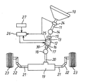
以下、本発明の第1の実施形態を図面に基づいて説明する。図1において、ステアリングホイール10が取付けられた操舵軸11は伝達比可変機構12の入力軸13に自在継手14および弾性継手15を介して接続されている。伝達比可変機構12の出力軸16は軸動機構17および自在継手18を介してステアリングギヤであるラックアンドピニオン機構19のピニオン軸(転舵軸)20に連結され回転を伝達する。ラックアンドピニオン機構19のラック軸21の両端にはそれぞれタイロッド22の一端が接続され、各タイロッド22の他端はナックルアームを介して転舵輪23に接続されている。ラックアンドピニオン機構19は、図略の車両のボディにゴムブッシュを介して固定されている。
DESCRIPTION OF EXEMPLARY EMBODIMENTS Hereinafter, a first embodiment of the invention will be described with reference to the drawings. In FIG. 1, a steering
操舵軸11にはステアリングホイール10の操舵角を検出する操舵角センサ24が設けられ、伝達比可変機構12には、後述するモータ39(モータ軸39a)の回転角から転舵輪23の転舵角を検出する転舵角センサ25が設けられている。これらステアリングホイール10の操舵角および転舵輪23の転舵角は電子制御装置26に入力される。電子制御装置26には車両速度を検出する車速センサ27から出力される車両速度も入力される。電子制御装置26は、これら操舵角、転舵角ならびに車両速度等に基づいて、伝達比可変機構12を制御するための制御信号を出力するようになっている。
The steering
弾性継手15は図2に示すように、同軸カップリング28および継手部29を備えている。同軸カップリング28は、内周軸30、外周軸31、および弾性部材32を備えている。内周軸30は、自在継手14のヨークにセレーション結合される第1結合軸部30a、および第1結合軸部30aより大径の第2結合軸部30bを有している。内周軸30と対向する外周軸31は、入力軸13にセレーション結合されたフランジ部材33に、ボルト34によって連結される第1連結部31a、および中空穴31dが穿設され第1結合軸部31aの外周を包囲する円筒状の円筒部31bを有している。第2結合軸部30bの外周と円筒部31bの中空穴31dの内周には、外筒体35および内筒体36に挟持された弾性部材32が介在されている。弾性部材32は、加硫ゴムから成り、外筒体35および内筒体36に加硫接着され、外筒体35、内筒体36および弾性部材32は、一体結合された状態で第2結合軸部30bと円筒部31bの間に圧入されている。なお、弾性部材32は、加硫ゴム以外にラバーゴムや軟質樹脂などを用いてもよい。
As shown in FIG. 2, the elastic joint 15 includes a
内周軸30の第1、第2結合軸部30a,30bの間には、図3に示すように径方向に延在する一対の板状のストッパフランジ部37が突設されている。ストッパフランジ部37の延在する先端は、外周軸31の円筒部31bの自在継手14側の一端に形成された切欠溝31cに回転方向に所定隙間を空けて係合されている。ストッパフランジ部37および切欠溝31cは、内周軸30と外周軸31との間に所定角度以上の相対回転が作用した場合に、ストッパフランジ部37が切欠溝31cの側壁に当接する。これにより、内周軸30と外周軸31では、弾性部材32を介さずに回転の伝達が行われ、内周軸30と外周軸31との間に過大なトルクが加わり、所定角度以上の相対回転が発生して弾性部材32が損傷することを防止している。
Between the first and second
伝達比可変機構12は、入力軸13と、ハウジング38内に収納されたモータ39および減速機構40と、出力軸16を備えている。入力軸13は、一端がフランジ部材33にセレーション結合され、他端がハウジング38に一体回転可能に結合されている。モータ39は、ハウジング38の内周面に固定され、電子制御装置26からの指令によりモータ39のモータ軸39aを回転させる。減速機構40はモータ軸39aの回転角を減速して出力軸16に伝達している。出力軸16は、ハウジング38に回転可能に支承され、軸動機構17の収納軸41に結合されている。
The transmission
軸動機構17は、収納軸41および収縮軸42を備え、収納軸41には摺動穴41aが穿設されている。収縮軸42には摺動穴41aにセレーションにより相対回転を規制して軸線方向に摺動可能に嵌合する摺動部42aが形成されている。摺動穴41aは、摺動部42a全体を収納可能な深さに形成され、車両衝突時にステアリングギヤ側の軸動がステアリングホイール10側に伝達されないように、収納軸41と収縮軸42とが軸線方向に相対的に収縮するコラプス機能を備えている。収縮軸42は、摺動部42aが形成された側と逆の端部が自在継手18のヨークに結合されている。
The
以上のような構成で、動作について説明する。運転手がステアリングホイール10を操作すると、操舵軸11が回転され、自在継手14および弾性継手15を介して伝達比可変機構12の入力軸13に回転が伝達される。伝達比可変機構12では、入力軸13から入力された操舵角を、操舵角センサ24、転舵角センサ25、および車速センサ27からの信号に基づいてモータ39の回転を制御して所定の伝達比で出力軸16に伝達する。出力軸16に伝達された回転は、軸動機構17および自在継手18を介して転舵軸20に伝達され、ラックアンドピニオン機構19により、転舵輪23が転舵される。このとき、同軸カップリング28は、軸線方向に弾性部材32が捩れることなく回転を伝達できる。このため、ステアリングホイール10の回転をロスなく転舵輪23に伝達する。また、伝達比可変機構12やラックアンドピニオン機構19で発生する振動や音は弾性部材32の弾性力により、ステアリングホイール10に伝達されることが防止される。
The operation will be described with the above configuration. When the driver operates the
そして、軸動機構17により、ステアリングホイール10とラックアンドピニオン機構19の間の軸線方向の相対移動が許容されることから、転舵輪23を介して伝達される路面の起伏に起因する軸線方向の変位を吸収することができる。
Since the
また、同軸カップリング28は、径方向の剛性が高いため、内周軸30と外周軸31の回転中心がずれることもない。このため、伝達比可変機構12が回転伝達経路の途中に配置されていても、この伝達比可変機構12が振れ回りすることがない。従って、振動や音を遮断するとともにステアリングホイール10の回転をロスなく転舵輪23に伝達できる。
Further, since the
さらに、軸動機構17は、車両衝突時のステアリングギヤ側の軸動がステアリングホイール12側に伝達されないように、収納軸41と収縮軸42とが軸線方向に相対的に収縮するコラプス機能を備えているので、回転伝達経路に別途コラプス機能を設ける必要がなく、ステアリング装置を小型化することができる。なお、上記実施の形態では、コラプス機能を付加した軸動機構17を示したが、転舵輪23を介して伝達される路面の起伏に起因する軸線方向の変位を吸収するだけであれば、軸動機構17は路面の起伏に起因する軸線方向の変位を吸収するだけの軸動が可能な深さに摺動穴41aを形成すればよい。
Further, the
また、軸動機構17の摺動部42aと摺動穴41aはセレーションによって結合する以外に、三角形、四角形、または六角形などの多角形の摺動穴41aと、この多角形の摺動穴41aと同形状の摺動部42aによって回転方向を規制して軸動が可能な軸動機構17としてもよい。
Besides, the sliding
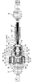
次に、本発明に係る第2の実施の形態について、第1の実施形態と相違する点を図4に基づいて説明する。第2の実施形態における弾性継手15は、同軸カップリング28のみを備え、同軸カップリング28の外周軸31の一端に形成された有底部57が伝達比可変機構12の入力軸13にセレーション結合されている。第2の実施形態では、図4において、伝達比可変機構12の入力軸13がハウジング38と一体的に成形され、ハウジング38と一体的に成形された入力軸13は、段付き円筒部13a、中間円筒部13bおよび底プレート部13cを一体的に連結して構成され、段付き円筒部13aの上方に突出した小径円筒部13dに外周軸31が共通軸線上でセレーション結合されている。入力軸13の底プレート部13cには出力軸16がフランジ部16aをスラスト軸受で回転可能に支承され、中間円筒部13b内にはフランジ部16a、減速機構40およびモータ39が共通軸線上に順次収容されている。出力軸16の軸部はダストシール43を貫通して入力軸13の外部に突出している。減速機構40は、一例として、波動歯車機構からなり、図5に詳細に示すように、中間円筒部13bにステータギヤ44が圧入結合され、フランジ部16aに回転連結されたドリブンギヤ45が回転可能に収容されている。
Next, a second embodiment according to the present invention will be described based on FIG. 4 with respect to differences from the first embodiment. The elastic joint 15 in the second embodiment includes only the
ステータギヤ44およびドリブンギヤ45内周面には、それぞれ異なる歯数(ドリブンギヤ45の歯数<ステータギヤ44の歯数)のギヤが形成されている。ステータギヤ44およびドリブンギヤ45の内側には、それぞれのギヤに同時に噛合するフレキシブルギヤ46が設けられている。すなわち、フレキシブルギヤ46の外側に形成された歯(歯数は、ドリブンギヤ45の歯数と同じ)に、ステータギヤ44およびドリブンギヤ45の内側に形成された歯が噛合している。フレキシブルギヤ46の内側は、波動発生装置47の外輪上に嵌合されている。波動発生装置47は、波動歯車機構の入力部材である楕円状のカム48の外周に軸受49の内輪が嵌着され、複数のボールにより回転可能に支持されたフレキシブルな外輪がフレキシブルギヤ46の内側に嵌合されている。
Gears having different numbers of teeth (the number of teeth of the driven
中間円筒部13bには、モータ39のケース50が嵌合されている。モータ39は、モータ軸39aを有し、モータ軸39aは先端をケース50に、中央部を中間プレート51に軸受52,53により回転可能に支持されている。段付き円筒部13aおよび中間円筒部13bは、ケース50のフランジと中間プレート51の外縁とを挟持した状態でカシメにより結合されている。出力軸16を支承した底プレート部13cは、波動歯車機構等を収容した中間円筒部13bにセレーション圧入され、カシメにより固定されている。
A
モータ軸39aには、退避空間である退避穴54が回転バランスをとって軸線方向に穿設され、モータ軸39の先端外周は、カム48に回転連結されている。
The
出力軸16は、第1実施の形態における軸動機構17の収納軸41を構成し、退避穴54に同一軸線上で連通する摺動穴41aが貫通して穿設されている。摺動穴41aは、図5に示すように、軸動穴41bおよび連通穴41cを備えている。軸動穴41bは出力軸16の一端に開口し、内周にセレーションが刻設されている。連通穴41cは、軸動穴41bの内径より大径に形成され、出力軸41の他端に開口するとともに前記軸動穴41bに同軸上に連通している。
The
56は段付き円筒部13aの大径部内に配設されたロック機構で、電源オフ時やシステム失陥時に、モータ軸39aを入力軸13に対して固定(ロック)し、ステアリングホイール10の回転を転舵輪23に伝達するものであるが、ロック機構56は既に公知の技術であるので、詳細な説明は省略する。また、ロック機構56と中間プレート51の間には、回転角センサ25が設けられている。回転角センサ25は、公知のレゾルバから構成され、モータ軸39aの回転を検出し、電子制御装置26に出力する。なお、回転角センサ25はモータ軸39aの回転角から出力軸16の回転角を検出する転舵角センサの機能も兼ねている。
58はスパイラルケーブル装置で、同軸カップリング28の外周に配置されている。スパイラルケーブル装置58は、外側筒体59、内側収納体60、およびフレキシブルフラットケーブル61を備え、外側筒体59が図略の車体に保持され、内側収納体60が段付き円筒部13aの小径円筒部13dの外周に嵌着されている。これら外側筒体59および内側収納体60によってケーブルケースが構成され、フレキシブルフラットケーブル61は、外側筒体59と内側収納体60の間に巻装され、一端が内側収納体60に固定されて内側収納体60の周囲に巻回され、他端が外側筒体59に固定されている。内側収納体60側でフレキシブルフラットケーブル61に接続され入力軸13内に導入されたリード線はモータ39のステータコイル等に接続され、外側筒体59側でフレキシブルフラットケーブル61に接続されたリード線は電子制御装置26、バッテリ等に接続されている。このように、スパイラルケーブル装置58の内周に同軸カップリング28が配置されることにより、回転伝達経路の軸方向長さを短くできるので、車両の搭載性を向上することができる。
A
軸動穴41bには、収縮軸42の摺動部42aが相対回転を規制して軸動可能にセレーション結合されている。摺動部42aの先端には、セレーションが形成されていない抜け止め部62が形成されている。抜け止め部62は、摺動部42aと同径の同径部62aと先端に向かって順次小径になるようにされたテーパ形状部62bを備え、テーパ形状部62bと同径部62aが接続される角部はR処理がなされている。この抜け止め部62が軸動穴41bと連通穴41cとの間の段部に係止されることにより、収縮軸42が収納軸41から脱落することを防止している。また、テーパ形状部62bにより、収縮軸42の連通穴41cおよび退避穴54での移動を円滑にしている。
A sliding
次に、上記した構成の伝達比可変機構12を備えたステアリング装置の作動を説明する。ロック機構56がアンロックされている状態において、運転手がステアリングホイール10を操舵すると、ステアリングホイール10の操舵角が操舵角センサ24によって検出される。電子制御装置26は、操舵角センサ24および転舵角センサ25からの操舵角および転舵角を入力するとともに、車速センサ27より車両速度を入力する。そして、電子制御装置26は車両速度および操舵角等に基づき目標転舵角の演算を行う。この目標転舵角と転舵角センサ25により検出され電子制御装置26にフィードバックされた転舵輪23の転舵角との差に基づいて、モータ39を制御する制御信号が電子制御装置26より出力される。
Next, the operation of the steering apparatus provided with the transmission
電子制御装置26より出力された制御信号は、伝達比可変機構12のモータ39に送られ、この制御信号に基づいてモータ39が作動され、モータ軸39aが回転される。モータ軸39aが回転すると、波動発生装置47のカム48が緩衝部材55を介して回転される。この際、フレキシブルギヤ46は楕円状に変形した状態でカム48の長軸の両端部分では、ステータギヤ44、ドリブンギヤ45と噛合し、短軸の両端部分ではステータギヤ44、ドリブンギヤ45から離れた状態になっている。この状態で波動発生装置47のカム48が回転されると、フレキシブルギヤ46の歯数がステータギヤ44の歯数より少ないため、波動発生装置47が1回転した際、フレキシブルギヤ46は、入力軸13に対して波動発生装置47の回転方向と逆方向に波動歯車機構の減速比だけ減速して回転される。フレキシブルギヤ46の回転は、噛合されているドリブンギヤ45に伝達されるドリブンギヤ45の回転速度は、ドリブンギヤ45の歯数とフレキシブルギヤ46の歯数が同一のため、フレキシブルギヤ46と同一となる。減速比はステータギヤ44とフレキシブルギヤ46の歯数差をドリブンギヤ45の歯数で除した値である。
The control signal output from the
ドリブンギヤ45により出力軸16が回転され、出力軸16の回転が軸動機構17および自在継手を介してラックアンドピニオン機構19のピニオン軸20に伝達され、ラック軸21を軸動させタイロッド22を介して転舵輪23を転舵させる。これにより、モータ軸39aの回転に応じてステアリングホイール10の操舵角と転舵輪23の転舵角との比を変化させることができる。
The
収縮軸42の先端と対向するモータ軸39aの後端部には、車両衝突時のステアリングギヤ側の軸動がステアリングホイール12側に伝達されないように、収納軸41と収縮軸42とが軸線方向に相対的に収縮するとき、退避穴54に収縮軸42の摺動部42aが入り込む。このため、軸動機構17の収縮軸42を伝達比可変機構12の内部に収納できることから、前記コラプス機能を達成するのに必要な摺動部42aの長さを少ないスペースで得ることができる。
In the rear end portion of the
上記の実施の形態において、図6に示すように軸動機構17を同軸カップリング28と自在継手14の間に設けてもよい。この場合、同軸カップリング28の内周軸30が軸動機構17の収納軸41と結合され、内周軸30には、モータ軸39aの退避穴54と連通する貫通穴55が穿設される。同様に外周軸31の有底部57に貫通穴66が穿設される。
In the above embodiment, as shown in FIG. 6, the
なお、外周軸31に穿設される貫通孔66は、外周軸31に有底部57を形成して入力軸13と結合したことにより必要になるものである。このため、有底部57を形成することなく外周軸31を入力軸13に結合するのであれば、貫通穴66は特に形成する必要がなく、収縮軸41を摺動穴41aおよび内周軸30の貫通穴55を通過して退避穴54に到達させることができる。
The through
以上のように、図6に示すように同軸カップリング28のと軸動機構17の収納軸41を結合し、同軸カップリング28の内周軸30に貫通穴55を穿設するとともに、伝達比可変機構12に退避穴54を形成したことにより、軸動機構17の収縮軸41が収納軸42の摺動穴42a、内周軸30の貫通穴55を通過して退避穴54に没入して収縮することが可能となる。よって、前記コラプス機能を達成するのに必要な収縮軸41のストロークを少ないスペースで得ることができる。
As described above, as shown in FIG. 6, the
なお、上記第2の実施の形態において、伝達比可変機構12の減速機構40を波動歯車機構としたが、減速機構40はこれに限定されるものではなく、例えば、サンギヤ、インターナルギヤ、およびプラネタリギヤ等からなる遊星歯車機構であってもよい。
In the second embodiment, the
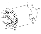
次に、本発明に係る同軸カップリング28の他の実施の形態を図7から図11に基づいて説明する。図7および図10に示すように、同軸カップリング28は、
Next, another embodiment of the
内周軸70、外周軸71を備えている。内周軸70は、自在継手14のヨークに結合される第1結合軸部70aおよび、第1結合軸部70aと同径の第2結合軸部70bを備えている。外周軸71は、内部に中空穴71aが形成された円筒状を成し、内周軸70と同軸上に第2結合部70bの外周を包囲するように配置され、一端が入力軸13に結合されている。
An inner
第2結合軸部70bの外周と外周軸71の中空穴71aの内周の間には、円筒部材63が配置されている。円筒部材63は内周軸70と同軸上に配置され、外周軸31と円筒部材63との間には、環状の第1弾性部材64が介在され、外周軸31と円筒部材63が結合される。内周軸70と円筒部材63との間には、環状の第2弾性部材65が介在され、内周軸70と円筒部材63が結合される。第1、第2弾性部材64,65は、所定のばね定数の剛性に設定されている。
A
内周軸70には、図8に示すように径方向に延在する板状の一対の第1ストッパフランジ部72が突設されている。第1ストッパフランジ部72の先端は、円筒部材63の一端に形成された切欠溝63aに回転方向に所定隙間を空けて係合されている(図8参照)。また、図9に示すように第1結合軸部70aと第2結合軸部70bの間には、第1ストッパフランジ部72と同様に径方向に延在する板状の一対の第2ストッパフランジ部73が突設され、第2ストッパフランジ部73の先端は、外周軸71の一端に形成された切欠溝71bに回転方向に所定隙間を空けて係合されている。
As shown in FIG. 8, a pair of plate-like first
以上のように構成した同軸カップリング28の動作について説明する。外周軸71が結合された伝達比可変機構12の入力軸13または、内周軸70が結合された自在継手14から回転が伝達され、内周軸70と外周軸71の間で回転が伝達されるとき、外周軸71と内周軸70の間に作用する回転力による捩れ角が第2ストッパフランジ部73が切欠溝63aに当接するまでの角度より小さいとき(相対角度θ以下のとき)には、第1、第2弾性部材64,65および円筒部材63を介して外周軸71と内周軸70の間の回転が伝達される。外周軸71と内周軸70の間の回転力による捩れ角が第2ストッパフランジ73が切欠溝63aに当接するまでの角度より大きくなると(相対角度がθ以上のとき)、内周軸70と円筒部材63に所定角度以上の相対回転が生じ、第1ストッパフランジ部72が切欠溝63aの側壁に当接し、第2弾性部材65を介さずに内周軸70と円筒部材63の間で回転が伝達される。このため、図11に示すように相対回転角度がθと−θの間の微小時においては、第1、第2弾性部材64,65および円筒部材63を介して外周軸71と内周軸70の間で回転が伝達される。従って、伝達されるトルクは、第1、第2弾性部材64,65のばね定数を合成した剛性値k1で伝達され、相対回転角度がθと−θの範囲を超えた場合においては、第2弾性部材65を介さずに内周軸70と円筒部材63の間で回転が伝達され、第1弾性部材64のばね定数の剛性値k2で伝達される。この結果、ステアリングホイール10に車両の運転操作に適した手ごたえ感を付与することができ、操縦安定性を向上させることができる。
The operation of the
なお、第2ストッパフランジ部73は、通常の運転時には発生しないような過剰な相対回転が発生したとき、(例えば、転舵輪が側溝に嵌った場合などで、転舵輪が固定状態となったとき)切欠溝71bの側壁に当接し、第1、第2弾性部材64,65および円筒部材63を介さずに外周軸71と内周軸70の間で回転を伝達し、第1、第2弾性部材64,65が損傷することを防止している。
Note that the second
以上のように構成された同軸カップリング28では、第1、第2弾性部材64,65のばね定数を適宜選定することにより、相対回転力の大きさによる外周軸71と内周軸70の間の捩れ剛性を変更して、適切な操舵特性を得ることができる。
In the
また、他の実施の形態に示した同軸カップリング28は、回転伝達経路の途中に伝達比可変機構12を備えていないステアリング装置においても相対回転力の大きさによる外周軸31と内周軸30の間の捩れ剛性を変更して、適切な操舵特性を得ることができる。
In addition, the
10…ステアリングホイール、11…操舵軸、12…伝達比可変機構、13…入力軸、13a…段付き円筒部、13b…中間円筒部、13c…底プレート部、13d…小径円筒部、14…自在継手、15…弾性継手、16…出力軸、16a…フランジ部、16b…軸部、17…軸動機構、18…自在継手、19…ラックアンドピニオン機構、20…転舵軸、21…ラック軸、22…タイロッド、23…転舵輪、24…操舵角センサ、25…転舵角センサ(回転角センサ)、26…電子制御装置、27…車速センサ、28…同軸カップリング、29…継手部、30,70…内周軸、30a,70a…第1結合軸部、30b,70b…第2結合軸部、31,71…外周軸、31a…第1連結部、31b…円筒部、31c,63c…切欠溝、31d,71a…中空穴、32…弾性部材、33…フランジ部材、34…ボルト、35…外筒体、36…内筒体、37…ストッパフランジ部、38…ハウジング、39…モータ、39a…モータ軸、40…減速機構、41…収納軸、41a…摺動穴、41b…軸動穴、41c…連通穴、42…収縮軸、42a…摺動部、43…ダストシール、44…ステータギヤ、45…ドリブンギヤ、46…フレキシブルギヤ、47…波動発生装置、48…カム、49…軸受、50…ケース、51…中間プレート、52…軸受、53…軸受、54…退避穴(退避空間)、55、66…貫通穴、56…ロック機構、57…有底部、58…スパイラルケーブル装置、59…外側筒体、60…内側収納体、61…フレキシブルフラットケーブル、62…抜け止め部、63…円筒部材、64…第1弾性部材、65…第2弾性部材、72…第1ストッパフランジ部、73…第2ストッパフランジ部。
DESCRIPTION OF
Claims (12)
前記回転伝達経路の途中に前記ステアリングホイールとステアリングギヤとの軸線方向の相対移動を許容する軸動機構を設け、
前記操舵軸および伝達比可変機構の一方に結合され中空穴が穿設された外周軸と、前記操舵軸および伝達比可変機構の他方に結合され前記中空穴に挿入される内周軸と、前記内周軸の外周面と前記中空穴の内周面の間に介在され前記外周軸と内周軸を結合する環状の弾性部材を備えた同軸カップリングを前記回転伝達経路の前記ステアリングホイールと前記伝達比可変機構との間に設けたことを特徴とするステアリング装置。 A steering shaft that transmits the rotation of the steering wheel, a steering shaft that transmits the rotation to a steering gear that imparts a steering angle to the steered wheels, and a steering shaft that is disposed between the steering shaft and the steering shaft. In a steering apparatus having a rotation transmission path composed of a transmission ratio variable mechanism that changes and transmits a ratio of a turning angle of a steered wheel to a steering angle,
An axial movement mechanism that allows relative movement in the axial direction between the steering wheel and the steering gear is provided in the middle of the rotation transmission path,
An outer peripheral shaft coupled to one of the steering shaft and the transmission ratio variable mechanism and having a hollow hole; an inner peripheral shaft coupled to the other of the steering shaft and the transmission ratio variable mechanism and inserted into the hollow hole; A coaxial coupling having an annular elastic member interposed between the outer peripheral surface of the inner peripheral shaft and the inner peripheral surface of the hollow hole and coupling the outer peripheral shaft and the inner peripheral shaft is connected to the steering wheel of the rotation transmission path and the steering wheel. A steering apparatus provided between the variable transmission ratio mechanism.
前記軸動機構は、軸線方向に摺動穴が穿設された収納軸と、前記摺動穴に相対回転を規制され軸線方向に摺動可能に嵌合する摺動部が形成された収縮軸とから成り、
車両衝突時の前記ステアリングギヤ側の軸動がステアリングホイール側に伝達しないように、前記収納軸と収縮軸とが軸線方向に相対的に収縮するコラプス機能を備えたことを特徴とするステアリング装置。 In claim 1,
The axial movement mechanism includes a retracting shaft in which a housing shaft having a sliding hole in the axial direction and a sliding portion that is slidably fitted in the axial direction with relative rotation regulated in the sliding hole. And
A steering apparatus, comprising: a collapse function in which the storage shaft and the contraction shaft are relatively contracted in the axial direction so that the axial movement on the steering gear side during a vehicle collision is not transmitted to the steering wheel side.
前記同軸カップリングの外周軸および内周軸の一方を前記伝達比可変機構の入力軸と結合し、
前記外周軸および内周軸の他方を前記軸動機構の収納軸および収縮軸の一方と結合し、前記収納軸および収縮軸の他方を前記操舵軸に連結したことを特徴とするステアリング装置。 In claim 2,
One of the outer peripheral shaft and the inner peripheral shaft of the coaxial coupling is coupled to the input shaft of the transmission ratio variable mechanism,
A steering device, wherein the other of the outer peripheral shaft and the inner peripheral shaft is coupled to one of a storage shaft and a contraction shaft of the axial movement mechanism, and the other of the storage shaft and the contraction shaft is connected to the steering shaft.
前記同軸カップリングの外周軸および内周軸の一方を前記伝達比可変機構の入力軸と結合し、前記外周軸および内周軸の他方を前記操舵軸と連結し、
前記伝達比可変機構の出力軸を前記軸動機構の収納軸とし、前記収縮軸を前記転舵軸に連結したことを特徴とするステアリング装置。 In claim 2,
One of an outer peripheral shaft and an inner peripheral shaft of the coaxial coupling is coupled to an input shaft of the transmission ratio variable mechanism, and the other of the outer peripheral shaft and the inner peripheral shaft is coupled to the steering shaft;
A steering apparatus characterized in that an output shaft of the transmission ratio variable mechanism is a storage shaft of the axial movement mechanism, and the contraction shaft is connected to the steered shaft.
前記同軸カップリングの外周軸および内周軸の一方を前記伝達比可変機構の入力軸と結合し、前記外周軸および内周軸の他方を前記軸動機構の収納軸と結合し、
前記収納軸と同軸に前記内周軸に貫通穴を穿設し、
前記収縮軸の摺動部が前記収納軸の摺動穴および前記貫通穴を通過して没入可能な中空の退避空間を前記伝達比可変機構内に形成したこと特徴とするステアリング装置。 In claim 3,
One of the outer peripheral shaft and the inner peripheral shaft of the coaxial coupling is coupled to the input shaft of the transmission ratio variable mechanism, and the other of the outer peripheral shaft and the inner peripheral shaft is coupled to the storage shaft of the axial movement mechanism,
A through hole is formed in the inner peripheral shaft coaxially with the storage shaft,
A steering apparatus, wherein a hollow evacuation space in which the sliding portion of the contraction shaft passes through the sliding hole and the through hole of the storage shaft and can be immersed is formed in the transmission ratio variable mechanism.
前記軸動機構の前記収納軸とされた出力軸に形成された摺動穴と連通し、前記収縮軸の摺動部が前記摺動穴を通過して没入可能な中空の退避空間を前記伝達比可変機構内に形成したことを特徴とするステアリング装置。 In claim 4,
The transmission mechanism communicates with a sliding hole formed in the output shaft, which is the storage shaft of the shaft movement mechanism, and the hollow retraction space in which the sliding portion of the contraction shaft passes through the sliding hole and can be immersed is transmitted. A steering apparatus characterized by being formed in a variable ratio mechanism.
前記軸動機構の収縮軸に形成された摺動部を前記伝達比可変機構の退避空間側に前記摺動穴から突出させ、前記突出した摺動部端に前記摺動穴との間の軸動を規制して該摺動穴から前記収縮軸が脱落することを防止する抜け止め部を形成したことを特徴とするステアリング装置。 In claim 5 or claim 6,
A sliding portion formed on the contraction shaft of the axial movement mechanism is projected from the sliding hole to the retracting space side of the transmission ratio variable mechanism, and an axis between the protruding sliding portion end and the sliding hole A steering device characterized in that a retaining portion for restricting movement to prevent the contraction shaft from falling off the sliding hole is formed.
前記抜け止め部に先端に向かって次第に径が小さくなるテーパ部を形成したことを特徴とするステアリング装置。 In claim 7,
A steering device characterized in that a taper portion having a diameter that gradually decreases toward the tip is formed in the retaining portion.
前記伝達比可変機構は、前記同軸カップリングの外周軸または内周軸が結合される入力軸と、前記転舵軸が結合される出力軸と、前記入力軸に同軸に固定されたモータと、前記モータと前記出力軸との間に設けられ前記モータの回転を減速して前記出力軸に伝達する減速機構と、スパイラルケーブル装置とを備え、
前記スパイラルケーブル装置は、前記モータと電気的に結合されるフレキシブルフラットケーブルが収納される円筒状のケーブルケースを前記同軸カップリングの外周を包囲して配置して成ることを特徴とするステアリング装置。 In any one of Claims 1 thru | or 8,
The transmission ratio variable mechanism includes an input shaft to which an outer peripheral shaft or an inner peripheral shaft of the coaxial coupling is coupled, an output shaft to which the steered shaft is coupled, a motor coaxially fixed to the input shaft, A reduction mechanism that is provided between the motor and the output shaft and decelerates rotation of the motor and transmits the rotation to the output shaft, and a spiral cable device;
The spiral cable device includes a cylindrical cable case in which a flexible flat cable electrically coupled to the motor is accommodated so as to surround an outer periphery of the coaxial coupling.
前記同軸カップリングは、前記内周軸の外周面と前記外周軸の中空穴内周面との間に円筒部材を配置し、前記中空穴と円筒部材との間を環状の第1弾性部材を介在して結合し、前記内周軸と円筒部材との間を環状の第2弾性部材を介在して結合し、前記内周軸に径方向に延在するストッパフランジ部を突設し、前記ストッパフランジ部と係合して前記内周軸と前記円筒部材との所定角度以上の相対回転を規制する切欠溝を円筒部材に形成して成ることを特徴とするステアリング装置。 In any one of Claims 1 thru | or 9,
In the coaxial coupling, a cylindrical member is disposed between the outer peripheral surface of the inner peripheral shaft and the inner peripheral surface of the hollow hole of the outer peripheral shaft, and an annular first elastic member is interposed between the hollow hole and the cylindrical member. And connecting the inner peripheral shaft and the cylindrical member via an annular second elastic member, and projecting a stopper flange portion extending in the radial direction on the inner peripheral shaft, A steering device comprising: a cylindrical member formed with a notch groove that engages with a flange portion and restricts relative rotation of the inner peripheral shaft and the cylindrical member over a predetermined angle.
Priority Applications (1)
| Application Number | Priority Date | Filing Date | Title |
|---|---|---|---|
| JP2005058369A JP2006240468A (en) | 2005-03-03 | 2005-03-03 | Steering device, and coaxial coupling |
Applications Claiming Priority (1)
| Application Number | Priority Date | Filing Date | Title |
|---|---|---|---|
| JP2005058369A JP2006240468A (en) | 2005-03-03 | 2005-03-03 | Steering device, and coaxial coupling |
Publications (2)
| Publication Number | Publication Date |
|---|---|
| JP2006240468A true JP2006240468A (en) | 2006-09-14 |
| JP2006240468A5 JP2006240468A5 (en) | 2008-04-17 |
Family
ID=37047296
Family Applications (1)
| Application Number | Title | Priority Date | Filing Date |
|---|---|---|---|
| JP2005058369A Pending JP2006240468A (en) | 2005-03-03 | 2005-03-03 | Steering device, and coaxial coupling |
Country Status (1)
| Country | Link |
|---|---|
| JP (1) | JP2006240468A (en) |
Cited By (3)
| Publication number | Priority date | Publication date | Assignee | Title |
|---|---|---|---|---|
| CN111332359A (en) * | 2018-12-19 | 2020-06-26 | 长城汽车股份有限公司 | Steering gear |
| CN112135767A (en) * | 2018-06-12 | 2020-12-25 | 株式会社昭和 | Steer-by-wire steering device and vehicle |
| CN114771647A (en) * | 2022-06-21 | 2022-07-22 | 太原理工大学 | Spiral variable transmission ratio mechanism, electro-hydraulic power steering system applying same and method |
Citations (6)
| Publication number | Priority date | Publication date | Assignee | Title |
|---|---|---|---|---|
| JPS6031955Y2 (en) * | 1979-08-06 | 1985-09-25 | 厚木自動車部品株式会社 | Steering shaft coupling |
| JP2000211541A (en) * | 1999-01-22 | 2000-08-02 | Toyota Motor Corp | Steering control device for vehicle |
| JP2003170839A (en) * | 2001-12-04 | 2003-06-17 | Toyoda Mach Works Ltd | Shock absorber for steering device |
| JP2003324836A (en) * | 2002-04-26 | 2003-11-14 | Toyoda Mach Works Ltd | Spiral cable device |
| JP2004322688A (en) * | 2003-04-21 | 2004-11-18 | Mitsubishi Automob Eng Co Ltd | Elastic shaft coupling |
| JP2005033925A (en) * | 2003-07-14 | 2005-02-03 | Favess Co Ltd | Spiral cable system |
-
2005
- 2005-03-03 JP JP2005058369A patent/JP2006240468A/en active Pending
Patent Citations (6)
| Publication number | Priority date | Publication date | Assignee | Title |
|---|---|---|---|---|
| JPS6031955Y2 (en) * | 1979-08-06 | 1985-09-25 | 厚木自動車部品株式会社 | Steering shaft coupling |
| JP2000211541A (en) * | 1999-01-22 | 2000-08-02 | Toyota Motor Corp | Steering control device for vehicle |
| JP2003170839A (en) * | 2001-12-04 | 2003-06-17 | Toyoda Mach Works Ltd | Shock absorber for steering device |
| JP2003324836A (en) * | 2002-04-26 | 2003-11-14 | Toyoda Mach Works Ltd | Spiral cable device |
| JP2004322688A (en) * | 2003-04-21 | 2004-11-18 | Mitsubishi Automob Eng Co Ltd | Elastic shaft coupling |
| JP2005033925A (en) * | 2003-07-14 | 2005-02-03 | Favess Co Ltd | Spiral cable system |
Cited By (3)
| Publication number | Priority date | Publication date | Assignee | Title |
|---|---|---|---|---|
| CN112135767A (en) * | 2018-06-12 | 2020-12-25 | 株式会社昭和 | Steer-by-wire steering device and vehicle |
| CN111332359A (en) * | 2018-12-19 | 2020-06-26 | 长城汽车股份有限公司 | Steering gear |
| CN114771647A (en) * | 2022-06-21 | 2022-07-22 | 太原理工大学 | Spiral variable transmission ratio mechanism, electro-hydraulic power steering system applying same and method |
Similar Documents
| Publication | Publication Date | Title |
|---|---|---|
| JP4315683B2 (en) | Driving device for automobile axle steering module and electromechanical automobile steering system | |
| JP2005042913A (en) | Worm speed reducer and electric power steering device | |
| US7891460B2 (en) | Gear box-typed active front steering system in vehicle | |
| JP4942843B2 (en) | Worm speed reducer and electric power steering device | |
| US9932065B2 (en) | Steering device | |
| JP2007145273A (en) | Steering device | |
| WO2003006301A1 (en) | Electronic control power steering device | |
| JP2010083327A (en) | Steering force transmission device for vehicle | |
| JP2006240468A (en) | Steering device, and coaxial coupling | |
| JP2006088726A (en) | Electric power steering device | |
| JP5262592B2 (en) | Steering force transmission device for vehicle | |
| US20220144335A1 (en) | Steer-by-wire steering apparatus | |
| JP2019214232A (en) | Steering unit for vehicle | |
| JP5374695B2 (en) | Steering force transmission device for vehicle | |
| JP3986389B2 (en) | Electric power steering device | |
| JP5434250B2 (en) | Vehicle steering damper device and steering device | |
| JP2004345483A (en) | Steering gear box | |
| JP2006044535A (en) | Steering device equipped with transmitting ratio varying mechanism | |
| KR101854108B1 (en) | Steering apparatus for vehicles | |
| US20230040073A1 (en) | Steer by wire type steering apparatus | |
| KR101246957B1 (en) | Intermediate Shaft of Steering Apparatus for Vehicle | |
| JP4604725B2 (en) | Electric actuator device | |
| JP4815983B2 (en) | Vehicle steering apparatus and method for assembling the same | |
| JP2010030397A (en) | Electric power steering system | |
| JP2008195354A (en) | Steering system |
Legal Events
| Date | Code | Title | Description |
|---|---|---|---|
| A711 | Notification of change in applicant |
Free format text: JAPANESE INTERMEDIATE CODE: A711 Effective date: 20060811 |
|
| A521 | Written amendment |
Free format text: JAPANESE INTERMEDIATE CODE: A523 Effective date: 20080229 |
|
| A621 | Written request for application examination |
Free format text: JAPANESE INTERMEDIATE CODE: A621 Effective date: 20080229 |
|
| A977 | Report on retrieval |
Free format text: JAPANESE INTERMEDIATE CODE: A971007 Effective date: 20100331 |
|
| A131 | Notification of reasons for refusal |
Free format text: JAPANESE INTERMEDIATE CODE: A131 Effective date: 20101109 |
|
| A521 | Written amendment |
Free format text: JAPANESE INTERMEDIATE CODE: A523 Effective date: 20110107 |
|
| A131 | Notification of reasons for refusal |
Free format text: JAPANESE INTERMEDIATE CODE: A131 Effective date: 20110726 |
|
| A02 | Decision of refusal |
Free format text: JAPANESE INTERMEDIATE CODE: A02 Effective date: 20120110 |