JP2006236955A - Multimedia outlet - Google Patents
Multimedia outlet Download PDFInfo
- Publication number
- JP2006236955A JP2006236955A JP2005056616A JP2005056616A JP2006236955A JP 2006236955 A JP2006236955 A JP 2006236955A JP 2005056616 A JP2005056616 A JP 2005056616A JP 2005056616 A JP2005056616 A JP 2005056616A JP 2006236955 A JP2006236955 A JP 2006236955A
- Authority
- JP
- Japan
- Prior art keywords
- telephone
- modular jack
- coaxial cable
- cable
- mounting
- Prior art date
- Legal status (The legal status is an assumption and is not a legal conclusion. Google has not performed a legal analysis and makes no representation as to the accuracy of the status listed.)
- Granted
Links
Images


Abstract
Description
本発明は、電源コンセントと共に各部屋の壁面などに設置され、テレビターミナル、電
話モジュラジャック及びLANモジュラジャックなどを備えたマルチメディアコンセント
に関する。
The present invention relates to a multimedia outlet provided on a wall surface of each room together with a power outlet and provided with a TV terminal, a telephone modular jack, a LAN modular jack, and the like.
近年、家庭内LANの普及により、各部屋の壁面に、電源コンセントやテレビターミナ
ルと共に電話モジュラジャックやLANモジュラジャックなどを備えたマルチメディアコ
ンセントが設置されつつある。従来のマルチメディアコンセントを図9に示す。この従来
のマルチメディアコンセントは、縦方向に最大3個のコンセントなどが配列可能な取付枠
10を横方向に3列並べたものであり、向かって左側から順に電源コンセント20、テレ
ビターミナル21、電話モジュラジャック22及びLANモジュラジャック23が配列さ
れている。
In recent years, with the widespread use of home LAN, multimedia outlets equipped with telephone modular jacks, LAN modular jacks, and the like are being installed on the wall surfaces of rooms together with power outlets and television terminals. A conventional multimedia outlet is shown in FIG. This conventional multimedia outlet has a
テレビターミナル21の背面の同軸ケーブル接続部21aには、先端部に同軸コネクタ
を備えた同軸ケーブル30(図10(b)参照)が接続されるが、この同軸ケーブルは太
く、かつ、堅いため、同軸ケーブルを急角度で曲げることは困難である。そのため、テレ
ビターミナル21は、設置スペースを必要とし、電話モジュラジャック22やLANモジ
ュラジャック23とは別に単独で配置されている。
A coaxial cable 30 (see FIG. 10B) having a coaxial connector at the tip is connected to the coaxial
このようなマルチメディアコンセントを用いることにより、テレビ用同軸ケーブル、電
話ケーブル及びLANケーブルを壁の内側に隠すことができるので、配線器具としてとて
も有用なものであるが、従来の単独の電源コンセント又は電源コンセントとテレビ用コン
セントを備えたものに比べて、壁面の専有面積が大きい。壁面の専有面積が大きくなると
、マルチメディアコンセントの設置場所が限定されたり、あるいは家具などの配置の自由
度が制限されたりするという問題を生じる。そのため、マルチメディアコンセントの小型
化が要求されている。
By using such a multimedia outlet, the coaxial cable for TV, telephone cable and LAN cable can be hidden inside the wall, so it is very useful as a wiring device. Compared to power outlets and TV outlets, the wall area is large. When the exclusive area of the wall surface becomes large, the installation location of the multimedia outlet is limited, or the degree of freedom of arrangement of furniture and the like is limited. Therefore, miniaturization of multimedia outlets is required.
図10は、従来のテレビターミナル21、電話モジュラジャック22及びLANモジュ
ラジャック23を、単純に1つの取付枠10の各装着部11〜13に装着した状態を示す
。図10から明らかなように、テレビ用同軸ケーブル30が電話モジュラジャック22及
びLANモジュラジャック23と配置上干渉して、同軸ケーブル30をテレビターミナル
21の同軸ケーブル接続部21aに接続することができない。なお、図10には描かれて
いないが、壁の内側にボックスが設置されている場合にも対応できなければいけないので
、テレビターミナル21を取付枠10の最下位の装着部13に設置することは妥当ではな
い。
FIG. 10 shows a state in which the
なお、マルチメディアコンセントにおけるテレビターミナル、電話モジュラジャック、
LANモジュラジャックなどの配置に関するものとしては、特許文献1に記載されたもの
が知られている。特許文献1に記載されたマルチメディアコンセントは、建築現場での取
付ミスの防止を目的としており、テレビターミナルの大きさを通常のテレビターミナル2
個分の大きさにしている。特許文献1では、マルチメディアコンセントの小型化は考慮さ
れていない。
As for the arrangement of the LAN modular jack or the like, the one described in
It is the size of the piece. In
本発明は、上記従来例の問題を解決するためになされたものであり、壁面の専有面積を
小さくすることが可能な小型のマルチメディアコンセントを提供することを目的とする。
The present invention has been made to solve the above-described problems of the conventional example, and an object of the present invention is to provide a small-sized multimedia outlet capable of reducing the exclusive area of the wall surface.
上記目的を達成するために請求項1の発明は、縦方向に3箇所の装着部を有する取付枠
と、少なくとも1つのテレビターミナル及び少なくとも1つの電話モジュラジャックを備
えたマルチメディアコンセントであって、前記電話モジュラジャックは前記テレビターミ
ナルに隣接して前記装着部に装着され、前記電話モジュラジャックの電話ケーブルとの結
線部は、前記テレビターミナルの背面の同軸ケーブル接続部にテレビ用同軸ケーブルを接
続した状態で、前記同軸ケーブルを前記取付枠の装着面に投影したときに陰になる部分以
外の位置に設けられていることを特徴とする。
In order to achieve the above object, the invention of
請求項2の発明は、請求項1のマルチメディアコンセントにおいて、前記テレビターミ
ナルの背面側の同軸ケーブル接続部が、前記取付枠の横方向の中心線に対して非平行とな
るように設けられており、前記電話モジュラジャックの電話ケーブルとの結線部は、前記
同軸ケーブル接続部に同軸ケーブルを接続した状態で、前記中心線に対して前記同軸ケー
ブルが引き出される側とは反対側に偏って設けられていることを特徴とする。
According to a second aspect of the present invention, in the multimedia outlet of the first aspect, the coaxial cable connecting portion on the rear side of the television terminal is provided so as to be non-parallel to the lateral center line of the mounting frame. And the connection part of the telephone modular jack with the telephone cable is provided in a state where the coaxial cable is connected to the coaxial cable connection part and is biased to the side opposite to the side from which the coaxial cable is drawn out with respect to the center line. It is characterized by being.
請求項3の発明は、請求項1のマルチメディアコンセントにおいて、前記電話モジュラ
ジャックの電話ケーブルとの結線部は、前記電話モジュラジャックの縦方向の中心線に対
して、前記テレビターミナルとは反対側に偏って設けられていることを特徴とする。
According to a third aspect of the present invention, in the multimedia outlet of the first aspect, the connection portion of the telephone modular jack with the telephone cable is opposite to the TV terminal with respect to the vertical center line of the telephone modular jack. It is characterized by being biased.
請求項4の発明は、請求項1乃至3のいずれかのマルチメディアコンセントにおいて、
前記テレビターミナルの同軸ケーブル接続部は、前記取付枠の装着面に対して垂直な方向
において、前記電話モジュラジャックの電話ケーブルとの結線部よりも前記装着面から遠
い位置に設けられていることを特徴とする。
The invention of claim 4 is the multimedia outlet according to any one of
The coaxial cable connecting portion of the television terminal is provided at a position farther from the mounting surface than the connection portion with the telephone cable of the telephone modular jack in a direction perpendicular to the mounting surface of the mounting frame. Features.
請求項5の発明は、請求項1のマルチメディアコンセントにおいて、前記取付枠の前面
に装着されるカバー部材をさらに備え、前記カバー部材は、前記取付枠の3つの装着部の
内前記テレビターミナル及び前記電話モジュラジャックが装着された装着部にそれぞれ対
向する位置に形成されたテレビ用同軸ケーブルの同軸コネクタが嵌装される同軸ケーブル
用開口と、電話ケーブルのモジュラプラグが嵌装される電話ケーブル用開口と、他の装着
部に対向する位置に形成されたLANケーブルのモジュラプラグが嵌装されるLANケー
ブル用開口と、前記LANケーブル用開口の近傍の背面に形成されたLANモジュラジャ
ック装着部を有し、前記LANモジュラジャックは、前記取付枠の前面に装着されるカバ
ー部材に対して着脱自在に構成されていることを特徴とする。
According to a fifth aspect of the present invention, the multimedia outlet of the first aspect further includes a cover member mounted on a front surface of the mounting frame, wherein the cover member includes the television terminal of the three mounting portions of the mounting frame, and An opening for a coaxial cable into which a coaxial connector of a coaxial cable for TV is formed, and a telephone cable in which a modular plug of the telephone cable is fitted, which are formed at positions facing the mounting portions where the telephone modular jack is mounted. An opening for the LAN cable in which the modular plug of the LAN cable formed at a position facing the opening and the other mounting part is fitted, and a LAN modular jack mounting part formed on the back surface in the vicinity of the LAN cable opening. The LAN modular jack is configured to be detachable from a cover member attached to the front surface of the mounting frame. It is characterized in that is.
請求項6の発明は、請求項1のマルチメディアコンセントにおいて、前記取付枠の他の
1つの装着部にLANモジュラジャックが装着されており、前記テレビターミナルの背面
側の同軸ケーブル接続部が、前記取付枠の横方向の中心線に対して非平行となるように設
けられており、前記LANモジュラジャックのLANケーブルとの結線部は、前記同軸ケ
ーブル接続部に同軸ケーブルを接続した状態で、前記中心線に対して前記同軸ケーブルが
引き出される側とは反対側に偏って設けられていることを特徴とする。
According to a sixth aspect of the present invention, in the multimedia outlet of the first aspect, a LAN modular jack is attached to another attachment portion of the mounting frame, and the coaxial cable connection portion on the back side of the television terminal is It is provided so as to be non-parallel to the lateral center line of the mounting frame, and the connection portion of the LAN modular jack with the LAN cable is connected to the coaxial cable connection portion in the state where the coaxial cable is connected. The coaxial cable is provided so as to be biased toward the side opposite to the side from which the coaxial cable is drawn out.
請求項7の発明は、請求項1のマルチメディアコンセントにおいて、少なくとも前記テ
レビターミナル及び前記電話モジュラジャックが同一のハウジングに一体化され、一体化
されたハウジングが前記取付枠の3つの装着部の全体に亘って装着されていることを特徴
とする。
According to a seventh aspect of the present invention, in the multimedia outlet of the first aspect, at least the television terminal and the telephone modular jack are integrated in the same housing, and the integrated housing is the whole of the three mounting portions of the mounting frame. It is mounted over the entire area.
請求項8の発明は、請求項1のマルチメディアコンセントにおいて、前記取付枠の3箇
所の装着部の全体に亘って装着されるカバー部材をさらに備え、前記カバー部材は、少な
くとも、その表面側からテレビ用同軸ケーブルの同軸コネクタ及び電話ケーブルのモジュ
ラプラグがそれぞれ挿入される同軸ケーブルの同軸コネクタ挿入孔及び電話ケーブルのモ
ジュラプラグ挿入孔と、その背面側の前記同軸ケーブルの同軸コネクタ挿入孔及び電話ケ
ーブルのモジュラプラグ挿入孔の近傍にそれぞれ形成されたテレビターミナル装着部及び
電話モジュラジャック装着部を有し、少なくとも前記テレビターミナル及び前記電話モジ
ュラジャックは、それぞれ前記カバー部材のテレビターミナル装着部及び電話モジュラジ
ャック装着部を介して前記取付枠に装着されていることを特徴とする。
The invention according to claim 8 is the multimedia outlet according to
請求項1の発明によれば、電話モジュラジャックの電話ケーブルとの結線部が、テレビ
ターミナルの背面の同軸ケーブル接続部にテレビ用同軸ケーブルを接続した状態で、同軸
ケーブルと物理的に干渉しない位置に設けられているので、電話モジュラジャックをテレ
ビターミナルに隣接して装着するという条件の下では、テレビターミナルと電話モジュラ
ジャックを同じ取付枠に装着することができる。取付枠の他の1つの装着部には、LAN
モジュラジャックを装着してもよいし、電話モジュラジャックをもう1つ装着してもよい
し、あるいはコンセントを装着しなくてもよい。また、テレビターミナルは取付枠の3つ
の装着部のうちどの位置にあってもよく、最上位又は中央に位置している場合は、同軸ケ
ーブルが下側から接続されるような向きに装着することが好ましい。また、テレビターミ
ナルが取付枠の装着部の最下位に位置しているときは、同軸ケーブルが上側から接続され
るような向きに装着する。それにより、壁の内側にボックスが設けられていても、マルチ
メディアコンセントの設置が可能である。なお、縦方向とは、取付枠が壁面に固定された
状態で垂直な方向を意味する。
According to the invention of
A modular jack may be attached, another telephone modular jack may be attached, or an outlet may not be attached. In addition, the TV terminal may be in any position of the three mounting parts of the mounting frame, and if it is positioned at the top or center, it should be mounted in such a direction that the coaxial cable is connected from below. Is preferred. When the television terminal is positioned at the lowest position of the mounting portion of the mounting frame, it is mounted so that the coaxial cable is connected from above. Thereby, even if a box is provided inside the wall, it is possible to install a multimedia outlet. The vertical direction means a direction perpendicular to the mounting frame fixed to the wall surface.
請求項2の発明によれば、テレビターミナルの背面側の同軸ケーブル接続部が、取付枠
の横方向の中心線に対して非平行、すなわち中心線に対して斜めに設けられているので、
同軸ケーブルは取付枠の中心線に対して斜め方向から接続され、かつ、斜め方向に引き出
される。また、電話モジュラジャックの電話ケーブルとの結線部は、同軸ケーブル接続部
に同軸ケーブルを接続した状態で、前記中心線に対して同軸ケーブルが引き出される側と
は反対側に偏って設けられているので、テレビ用同軸ケーブルと電話モジュラジャックの
結線部又は電話ケーブルとの距離を確保することができる。また、電話モジュラジャック
と電話ケーブルの結線作業がテレビターミナルの同軸ケーブル接続部によって妨げられる
ことがなく、結線作業を効率良く行うことができる。なお、横方向とは、取付枠が壁面に
固定された状態で水平な方向を意味する。テレビターミナルは、上下を逆にして取付枠に
装着することが可能である。一方、電話モジュラジャック及びLANモジュラジャックは
、モジュラジャックのカバーなどの方向性があるため、上下を逆にして取付枠に装着する
ことはできない。従って、テレビターミナルを取付枠の3つの装着部の最下位に装着する
場合、それ以外の位置に装着する場合と同じテレビターミナル又は電話モジュラジャック
を用いることはできないので、テレビターミナル又は電話モジュラジャックを左右対称に
した2種類用意する必要がある。
According to the invention of
The coaxial cable is connected to the center line of the mounting frame from an oblique direction, and is drawn out in an oblique direction. Further, the connection portion of the telephone modular jack with the telephone cable is provided in a state where the coaxial cable is connected to the coaxial cable connection portion and is biased to the side opposite to the side from which the coaxial cable is drawn with respect to the center line. Therefore, the distance between the coaxial cable for television and the connecting portion of the telephone modular jack or the telephone cable can be secured. In addition, the connection work between the telephone modular jack and the telephone cable is not hindered by the coaxial cable connecting portion of the television terminal, and the connection work can be performed efficiently. The lateral direction means a horizontal direction in a state where the mounting frame is fixed to the wall surface. The TV terminal can be mounted on the mounting frame upside down. On the other hand, since the telephone modular jack and the LAN modular jack have a directionality such as a cover of the modular jack, they cannot be mounted on the mounting frame upside down. Therefore, when the TV terminal is mounted at the bottom of the three mounting portions of the mounting frame, the same TV terminal or telephone modular jack as that used for mounting at other positions cannot be used. It is necessary to prepare two types that are symmetric.
請求項3の発明によれば、電話モジュラジャックの電話ケーブルとの結線部が、電話モ
ジュラジャックの縦方向の中心線に対して、テレビターミナルとは反対側に偏って設けら
れているので、電話モジュラジャックの電話ケーブルとの結線部とテレビターミナルの同
軸ケーブル接続部の距離をさらに遠くすることができる。そのため、電話モジュラジャッ
クと電話ケーブルの結線作業をさらに効率良く行うことができる。
According to the third aspect of the present invention, the connection portion of the telephone modular jack with the telephone cable is provided on the opposite side of the TV terminal with respect to the vertical center line of the telephone modular jack. The distance between the modular jack telephone cable connection and the TV terminal coaxial cable connection can be further increased. Therefore, the work of connecting the telephone modular jack and the telephone cable can be performed more efficiently.
請求項4の発明によれば、テレビターミナルの同軸ケーブル接続部が、取付枠の装着面
に対して垂直な方向(壁の奥行き方向)において、電話モジュラジャックの電話ケーブル
との結線部よりも装着面から遠い位置に設けられているので、取付枠を下にして結線作業
を行うと仮定すると、テレビ用同軸ケーブルが電話ケーブルの上側に位置する。そのため
、テレビ用同軸ケーブルと電話ケーブルとが干渉することを防止することができると共に
、壁の裏側での配線処理をスムーズに行うことができる。
According to the invention of claim 4, the coaxial cable connecting portion of the television terminal is mounted more in the direction perpendicular to the mounting surface of the mounting frame (in the depth direction of the wall) than the connecting portion with the telephone cable of the telephone modular jack. Since it is provided at a position far from the surface, the coaxial cable for television is positioned on the upper side of the telephone cable, assuming that the connection work is performed with the mounting frame down. Therefore, interference between the television coaxial cable and the telephone cable can be prevented, and wiring processing on the back side of the wall can be performed smoothly.
一般的に、LANモジュラジャックの本体部は、テレビターミナルの本体部に比べて小
さいので、テレビターミナルや電話モジュラジャックと同じ取付枠に装着するために、モ
ジュラジャック本体部よりも大きなベース部を有している。そのため、請求項5の発明に
よれば、LANモジュラジャックを取付枠に直接装着するのではなく、取付枠の前面に装
着されるカバー部材に装着する用に構成したので、取付枠に予めテレビターミナルと電話
モジュラジャックのみを装着しておき、電話モジュラジャックに電話ケーブルを結線し、
さらにテレビターミナルに同軸ケーブルを接続した後、別にLANケーブルと結線された
LANモジュラジャックをカバー部材に装着し、最後にカバー部材を取付枠に装着するこ
とができる。その結果、LANモジュラジャックとLANケーブル結線作業がテレビター
ミナルの同軸ケーブル接続部によって妨げられることがなく、結線作業を効率良く行うこ
とができる。
Generally, the LAN modular jack main body is smaller than the TV terminal main body, so it has a larger base than the modular jack main body to be mounted on the same mounting frame as the TV terminal or telephone modular jack. is doing. Therefore, according to the invention of claim 5, since the LAN modular jack is not mounted directly on the mounting frame but is mounted on the cover member mounted on the front surface of the mounting frame, the TV terminal is previously attached to the mounting frame. And only install the telephone modular jack, connect the telephone cable to the telephone modular jack,
Furthermore, after connecting the coaxial cable to the television terminal, a LAN modular jack connected to the LAN cable can be separately attached to the cover member, and finally the cover member can be attached to the mounting frame. As a result, the LAN modular jack and the LAN cable connection work are not hindered by the coaxial cable connecting portion of the television terminal, and the connection work can be performed efficiently.
請求項6の発明によれば、取付枠の他の1つの装着部にLANモジュラジャックが装着
されている場合、請求項2の発明の場合と同様に、テレビターミナルの背面側の同軸ケー
ブル接続部が、取付枠の横方向の中心線に対して非平行、すなわち中心線に対して斜めに
設けられているので、同軸ケーブルは取付枠の中心線に対して斜め方向から接続される。
また、LANモジュラジャックのLANケーブルとの結線部は、同軸ケーブル接続部に同
軸ケーブルを接続した状態で、前記中心線に対して同軸ケーブルが引き出される側とは反
対側に偏って設けられているので、テレビ用同軸ケーブルとLANケーブルとの距離を確
保することができる。また、LANモジュラジャックとLANケーブルの結線作業がテレ
ビターミナルの同軸ケーブル接続部によって妨げられることがなく、結線作業を効率良く
行うことができる。
According to the invention of claim 6, when the LAN modular jack is attached to the other attachment part of the mounting frame, the coaxial cable connection part on the rear side of the television terminal is provided as in the case of the invention of
Further, the connection portion of the LAN modular jack with the LAN cable is provided on the opposite side to the side from which the coaxial cable is drawn with respect to the center line in a state where the coaxial cable is connected to the coaxial cable connection portion. Therefore, the distance between the coaxial cable for TV and the LAN cable can be secured. Further, the connection work between the LAN modular jack and the LAN cable is not hindered by the coaxial cable connecting portion of the television terminal, and the connection work can be performed efficiently.
請求項7の発明によれば、少なくともテレビターミナル及び電話モジュラジャックが同
一のハウジングに一体化されているので、建築現場での結線作業の際、テレビターミナル
及び電話モジュラジャックの取付ミスを防止することができる。なお、必要に応じてLA
Nモジュラジャックをテレビターミナル及び電話モジュラジャックと共に一体化してもよ
いことは言うまでもない。
According to the invention of claim 7, since at least the television terminal and the telephone modular jack are integrated in the same housing, it is possible to prevent a mistake in mounting the television terminal and the telephone modular jack at the time of connection work at a construction site. Can do. If necessary, LA
It goes without saying that the N modular jack may be integrated with the TV terminal and the telephone modular jack.
請求項8の発明によれば、少なくともテレビターミナル及び電話モジュラジャックが、
汎用の取付枠に直接装着されるのではなく、専用のカバー部材を介して装着されるので、
上記請求項7の場合と同様に、建築現場での結線作業の際、テレビターミナル及び電話モ
ジュラジャックの取付ミスを防止することができる。また、必要に応じてLANモジュラ
ジャックをテレビターミナル及び電話モジュラジャックと共にカバー部材に装着してもよ
いことは言うまでもない。
According to the invention of claim 8, at least the TV terminal and the telephone modular jack are
Rather than being mounted directly on a general-purpose mounting frame, it is mounted via a dedicated cover member.
As in the case of the seventh aspect, it is possible to prevent a mistake in attaching the TV terminal and the telephone modular jack during the connection work at the construction site. Needless to say, the LAN modular jack may be attached to the cover member together with the television terminal and the telephone modular jack as necessary.
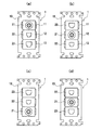
本発明の一実施形態に係るマルチメディアコンセントについて説明する。図1(a)〜
(d)は、それぞれ本実施形態におけるマルチメディアコンセント1の配置のバリエーシ
ョンを示す正面図である。各図に示すように、取付枠10は、3個のコンセントを縦方向
(取付枠が壁面に固定された状態で上下な方向)に配列して装着可能なように3箇所の装
着部11、12及び13を有する。この取付枠10は、従来から使用されている汎用品で
ある。本実施形態では、3つの装着部11〜13にそれぞれテレビターミナル21、電話
モジュラジャック22及びLANモジュラジャック23がそれぞれ装着されている。そし
て、必ず電話モジュラジャック22はテレビターミナル21に隣接して装着されている。
A multimedia outlet according to an embodiment of the present invention will be described. FIG.
(D) is a front view which shows the variation of arrangement | positioning of the
電話モジュラジャック22及びLANモジュラジャック23の背面にも、電話ケーブル
やLANケーブルと接続するための結線部22a及び23a(図10(b)参照)が設け
られている。電話ケーブルに比べてLANケーブルの方がその内部の線数が多い。そのた
め、一般的に、LANモジュラジャック23の結線部23aの方が電話モジュラジャック
の結線部よりも奥行きが大きい。また、LANケーブルの方が電話ケーブルよりも直径が
太く、急角度に曲げることは困難である。そのため、テレビターミナル21に隣接して電
話モジュラジャック22を装着することにより、テレビ用同軸ケーブル30(図2(b)
など参照)を引き回すスペースをより広く確保することができる。
Also on the back of the telephone
Etc.) can be secured more widely.
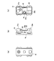
図2(a)〜(c)は、マルチメディアコンセント1の背面図であって、特に隣接する
テレビターミナル21と電話モジュラジャック22の構成を示している。テレビターミナ
ル21の背面に設けられた同軸ケーブル接続部21aは、取付枠10の横方向(取付枠1
0が壁面に固定された状態で水平な方向)の中心線L1に対して所定角度を成すように、
非平行に設けられている。同軸ケーブル接続部21aと同軸ケーブル30との接続は、取
付枠10の装着面10a(図3参照)と平行な面上で行われ、同軸ケーブル30は取付枠
10の装着面10aと略平行で、かつ中心線L1に対して上記所定角度を成すように引き
出される。
FIGS. 2A to 2C are rear views of the
In order to form a predetermined angle with respect to the center line L1 in the horizontal direction with 0 being fixed to the wall surface,
It is provided non-parallel. The coaxial
一方、電話モジュラジャック22の電話ケーブルとの結線部22aは、中心線L1に対
して同軸ケーブル30が引き出される側とは反対側に偏って設けられている。図2(a)
〜(c)では、それぞれ同軸ケーブル30は中心線L1よりも右側に引き出され、電話モ
ジュラジャック22の結線部22aは、中心線L1よりも左側に設けられている。また、
図2(a)では、電話モジュラジャック22の結線部22aは、電話モジュラジャック2
2の縦方向の中心線L2に対してテレビターミナル21側に偏った位置に設けられている
。図2(b)では、結線部22aは、電話モジュラジャック22の縦方向の中心線L2に
対して略対称の位置に設けられている。図2(c)では、結線部22aは、電話モジュラ
ジャック22の縦方向の中心線L2に対してテレビターミナル21とは反対側に偏った位
置に設けられている。
On the other hand, the
In (c), the
In FIG. 2 (a), the
2 is provided at a position biased toward the
電話モジュラジャック22の結線部22aは、4本の電線の先端部が絶縁被覆を剥がさ
れた状態で挿入される4つの孔と、各孔の内部に嵌装された端子と、各電線の先端部をそ
れぞれ端子に圧接させるばねなどで構成されている、いわゆる速結端子である。一般的に
、テレビ用同軸ケーブルは、その先端に同軸コネクタが設けられており、テレビターミナ
ル21の同軸ケーブル接続部21aとの接続作業は容易である。それに対して、電話モジ
ュラジャック22の結線部22aと電話ケーブルの接続には、電線の絶縁被覆を剥離する
作業などが必要である。そのため、建築現場などで行われる結線作業では、通常、先に電
話モジュラジャック22の結線部22aに電話ケーブルを結線し、そのあとで同軸ケーブ
ル30をテレビターミナル21の同軸ケーブル接続部21aに接続する。そのため、電話
モジュラジャック22の結線部22aは、テレビターミナル21の同軸ケーブル接続部2
1aに同軸ケーブル30を接続した状態で、同軸ケーブル30を取付枠10の装着面に投
影したときに陰になる部分以外の位置に設けられていれば十分である。それにより、テレ
ビ用同軸ケーブル30と電話モジュラジャック22の結線部22a又は電話ケーブルとの
距離を確保することができると共に、電話モジュラジャック22の結線部22aと電話ケ
ーブルの結線作業がテレビターミナル21の同軸ケーブル接続部21aによって妨げられ
ることがなく、結線作業を効率良く行うことができる。なお、図2(c)に示すように、
電話モジュラジャック22の結線部22aを、電話モジュラジャック22の縦方向の中心
線L2に対して、テレビターミナル21とは反対側に偏って設けることにより、電話モジ
ュラジャック22の結線部22aとテレビターミナル21の同軸ケーブル接続部21aの
距離をさらに遠くすることができる。そのため、電話モジュラジャック22と電話ケーブ
ルの結線作業をさらに効率良く行うことができる。
The
It is sufficient that the
By connecting the
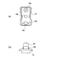
さらに、図3に示すように、テレビターミナル21の同軸ケーブル接続部21aは、取
付枠10の装着面10aに対して垂直な方向(壁の奥行き方向)において、電話モジュラ
ジャック22の電話ケーブルとの結線部22aよりも装着面10aから遠い位置に設けら
れている。建築現場において、取付枠10を下にして結線作業を行うと仮定すると、テレ
ビ用同軸ケーブル30が電話ケーブル(図示せず)の上側に位置する。そのため、テレビ
用同軸ケーブル30と電話ケーブルとが干渉することを防止することができる。また、結
線作業を終えたマルチメディアコンセント1を壁面に固定する際、壁の裏側での配線処理
をスムーズに行うことができる。
Further, as shown in FIG. 3, the coaxial
一般的に、LANモジュラジャック23の本体部は、テレビターミナル21の本体部や
電話モジュラジャック22の本体部に比べて幅方向及び厚さ方向において小さいので、テ
レビターミナル21や電話モジュラジャック22と同じ汎用の取付枠10に装着するため
に、モジュラジャック本体部よりも大きなベース部を有している。本出願人は、例えば特
開2004−319207号公報に記載されているように、建築現場でも比較的容易に結
線作業を行うことができる小型で汎用性のあるモジュラジャックを提案している。図4は
、このような小型のモジュラジャックをLANモジュラジャック23’とし、LANモジ
ュラジャック23’を取付枠10の装着部11〜13に直接装着するのではなく、取付枠
10の前面に装着されるカバー部材15に装着した変形例を示している。その場合、取付
枠10にはテレビターミナル21及び電話モジュラジャック22のみを装着しておき、電
話モジュラジャック22に電話ケーブルを結線し、さらにテレビターミナル21に同軸ケ
ーブル30を接続した後、別にLANケーブルと結線されたLANモジュラジャック23
’をカバー部材15に装着し、最後にカバー部材15を取付枠10に装着する。それによ
り、LANモジュラジャック23’とLANケーブル結線作業がテレビターミナル21の
同軸ケーブル接続部21aなどによって妨げられることがなく、結線作業を効率良く行う
ことができる。
In general, the main body of the LAN
'Is attached to the
カバー部材15は、取付枠10の3つの装着部11〜13の内、テレビターミナル21
及び電話モジュラジャック22が装着された装着部(例えば11及び12)にそれぞれ対
向する位置に形成されたテレビ用同軸ケーブルの同軸コネクタが嵌装される同軸ケーブル
用開口15aと、電話ケーブルのモジュラプラグが嵌装される電話ケーブル用開口15b
と、他の装着部(例えば13)に対向する位置に形成されたLANケーブルのモジュラプ
ラグが嵌装されるLANケーブル用開口15cと、LANケーブル用開口15cの近傍の
背面に形成されたLANモジュラジャック装着部15dを有し、LANモジュラジャック
23’は、カバー部材15のLANモジュラジャック装着部15dに対して着脱自在に構
成されている。
The
And a
A LAN cable opening 15c into which a modular plug of a LAN cable formed at a position facing another mounting portion (for example, 13) is fitted, and a LAN modular formed on the back surface in the vicinity of the
図5は、LANモジュラジャック23の他の構成例を示す図であり、(a)は背面図、
(b)は底面図である。但し、図5(b)では同軸ケーブル接続部21aを省略している
。LANモジュラジャック23のLANケーブルとの結線部23aは、テレビターミナル
21の同軸ケーブル接続部21aに同軸ケーブル30を接続した状態で、中心線L1に対
して同軸ケーブル30が引き出される側とは反対側に偏って設けられている。このような
構成により、テレビ用同軸ケーブル30とLANケーブル(図示せず)との距離を確保す
ることができる。また、LANモジュラジャック23とLANケーブルの結線作業がテレ
ビターミナルの同軸ケーブル接続部によって妨げられることがなく、結線作業を効率良く
行うことができる。
FIG. 5 is a diagram showing another configuration example of the LAN
(B) is a bottom view. However, the coaxial
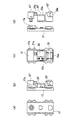
図6は、LANモジュラジャック23がテレビターミナル21に隣接して設けられた変
形例を示す。取付枠10にテレビターミナル21及びLANモジュラジャック23が隣接
して装着されている状態では、LANモジュラジャック23の結線部23aにLANコー
ドを結線する作業は非常に困難である。しかしながら、上記のようにLANモジュラジャ
ック23のモジュラジャック本体部をベース部材に対して着脱可能にすれば、このような
構成も可能である。その場合、LANモジュラジャック23のLANケーブルとの結線部
23aが中心線L1に対して同軸ケーブル30が引き出される側とは反対側に偏って設け
られているので、テレビ用同軸ケーブル30とLANモジュラジャック23の結線部23
a又は結線部に結線されたLANケーブルが物理的に干渉することはない。
FIG. 6 shows a modification in which the LAN
a or the LAN cable connected to the connection part does not physically interfere.
図7は、テレビターミナル21、電話モジュラジャック22及びLANモジュラジャッ
ク23が、同一のハウジング16に一体化された変形例を示す。この変形例では、一体化
されたハウジング16が、取付枠10の3つの装着部11〜13の全体に亘って装着され
る。このように、テレビターミナル21、電話モジュラジャック22及びLANモジュラ
ジャック23を、同一のハウジング16に一体化することにより、建築現場での結線作業
の際、テレビターミナル及び電話モジュラジャックの取付ミスを防止することができる。
FIG. 7 shows a modification in which the
図8は、テレビターミナル21、電話モジュラジャック22及びLANモジュラジャッ
ク23をそれぞれ取付枠10の装着部11〜13に直接装着可能な汎用品とせず、それぞ
れを独自規格のモジュール21”、22”及び23”とし、各モジュールを取付枠10の
装着部11〜13に装着されるカバー部材又は取付枠10を兼ねたカバー部材17に装着
した変形例を示す。カバー部材17の背面には、各モジュール21”、22”及び23”
が着脱可能に係合される爪などの装着部17aが形成されている。図7に示す変形例との
違いは、各モジュール21”、22”及び23”がハウジングに一体化されていないため
、用途に応じて様々なモジュールの組み合わせが可能である。例えば、テレビターミナル
モジュール21”としては、分配配線用のテレビターミナルや送り配線用の中継用/端末
用テレビターミナルなどとすることができる。また、LANモジュラジャックモジュール
23”としても、CAT5E(カテゴリー5E)対応のものやCAT6(カテゴリー6)
対応のものなど、用途に応じて様々なものを組み合わせることができる。
In FIG. 8, the
A mounting
Various things such as compatible ones can be combined depending on the application.
なお、上記各実施形態では、同軸ケーブル接続部21aとして同軸コネクタが接続され
るタイプのものを例示したが、本発明はこれに限定されるものではなく、同軸ケーブルの
絶縁被覆を剥離して心線を露出させ、その心線を直接ねじ止めするタイプのものであって
もよく、その場合でも同様の効果が得られることは言うまでもない。
In each of the above embodiments, the coaxial
1 マルチメディアコンセント
10 取付枠
10a 装着面
11〜13 装着部
15、17 カバー部材
16 ハウジング
21 テレビターミナル
21a 同軸ケーブル接続部
22 電話モジュラジャック
22a 結線部
23、23’ LANモジュラジャック
23a 結線部
21”〜23” モジュール
30 同軸ケーブル
DESCRIPTION OF
Claims (8)
なくとも1つの電話モジュラジャックを備えたマルチメディアコンセントであって、
前記電話モジュラジャックは前記テレビターミナルに隣接して前記装着部に装着され、
前記電話モジュラジャックの電話ケーブルとの結線部は、前記テレビターミナルの背面
の同軸ケーブル接続部にテレビ用同軸ケーブルを接続した状態で、前記同軸ケーブルを前
記取付枠の装着面に投影したときに陰になる部分以外の位置に設けられていることを特徴
とするマルチメディアコンセント。 A multimedia outlet comprising a mounting frame having three mounting portions in the vertical direction, at least one TV terminal and at least one telephone modular jack,
The telephone modular jack is mounted on the mounting portion adjacent to the TV terminal;
The connection portion of the telephone modular jack to the telephone cable is shaded when the coaxial cable is projected onto the mounting surface of the mounting frame in a state where the coaxial cable for television is connected to the coaxial cable connection portion on the back of the television terminal. Multimedia outlet characterized by being provided at a position other than the part to become.
に対して非平行となるように設けられており、
前記電話モジュラジャックの電話ケーブルとの結線部は、前記同軸ケーブル接続部に同
軸ケーブルを接続した状態で、前記中心線に対して前記同軸ケーブルが引き出される側と
は反対側に偏って設けられていることを特徴とする請求項1のマルチメディアコンセント
。 The coaxial cable connecting portion on the back side of the TV terminal is provided so as to be non-parallel to the horizontal center line of the mounting frame,
The connection part of the telephone modular jack with the telephone cable is provided in a state where the coaxial cable is connected to the coaxial cable connection part and is biased to the opposite side to the side from which the coaxial cable is drawn with respect to the center line. The multimedia outlet according to claim 1, wherein:
縦方向の中心線に対して、前記テレビターミナルとは反対側に偏って設けられていること
を特徴とする請求項1のマルチメディアコンセント。 2. The connection portion of the telephone modular jack with a telephone cable is provided so as to be biased to the opposite side of the television terminal with respect to a longitudinal center line of the telephone modular jack. Multimedia outlet.
向において、前記電話モジュラジャックの電話ケーブルとの結線部よりも前記装着面から
遠い位置に設けられていることを特徴とする請求項1乃至3のいずれかのマルチメディア
コンセント。 The coaxial cable connecting portion of the television terminal is provided at a position farther from the mounting surface than the connection portion with the telephone cable of the telephone modular jack in a direction perpendicular to the mounting surface of the mounting frame. The multimedia outlet according to any one of claims 1 to 3.
前記カバー部材は、前記取付枠の3つの装着部の内前記テレビターミナル及び前記電話
モジュラジャックが装着された装着部にそれぞれ対向する位置に形成されたテレビ用同軸
ケーブルの同軸コネクタが嵌装される同軸ケーブル用開口と、電話ケーブルのモジュラプ
ラグが嵌装される電話ケーブル用開口と、他の装着部に対向する位置に形成されたLAN
ケーブルのモジュラプラグが嵌装されるLANケーブル用開口と、前記LANケーブル用
開口の近傍の背面に形成されたLANモジュラジャック装着部を有し、
前記LANモジュラジャックは、前記取付枠の前面に装着されるカバー部材に対して着
脱自在に構成されていることを特徴とする請求項1のマルチメディアコンセント。 A cover member mounted on the front surface of the mounting frame;
The cover member is fitted with a coaxial connector of a coaxial cable for television formed at a position facing the television terminal and the attachment portion to which the telephone modular jack is attached, among the three attachment portions of the mounting frame. A coaxial cable opening, a telephone cable opening into which a telephone cable modular plug is fitted, and a LAN formed at a position facing other mounting portions.
A LAN cable opening in which a modular plug of the cable is fitted, and a LAN modular jack mounting portion formed on the back surface in the vicinity of the LAN cable opening;
2. The multimedia outlet according to claim 1, wherein the LAN modular jack is configured to be detachable from a cover member mounted on the front surface of the mounting frame.
前記テレビターミナルの背面側の同軸ケーブル接続部が、前記取付枠の横方向の中心線
に対して非平行となるように設けられており、
前記LANモジュラジャックのLANケーブルとの結線部は、前記同軸ケーブル接続部
に同軸ケーブルを接続した状態で、前記中心線に対して前記同軸ケーブルが引き出される
側とは反対側に偏って設けられていることを特徴とする請求項1のマルチメディアコンセ
ント。 A LAN modular jack is mounted on the other mounting portion of the mounting frame,
The coaxial cable connecting portion on the back side of the TV terminal is provided so as to be non-parallel to the horizontal center line of the mounting frame,
The connection portion of the LAN modular jack with the LAN cable is provided on the opposite side to the side from which the coaxial cable is drawn with respect to the center line in a state where the coaxial cable is connected to the coaxial cable connection portion. The multimedia outlet according to claim 1, wherein:
に一体化され、一体化されたハウジングが前記取付枠の3つの装着部の全体に亘って装着
されていることを特徴とする請求項1のマルチメディアコンセント。 2. At least the television terminal and the telephone modular jack are integrated in the same housing, and the integrated housing is mounted over the entire three mounting portions of the mounting frame. Multimedia outlet.
前記カバー部材は、少なくとも、その表面側からテレビ用同軸ケーブルの同軸コネクタ
及び電話ケーブルのモジュラプラグがそれぞれ挿入される同軸ケーブルの同軸コネクタ挿
入孔及び電話ケーブルのモジュラプラグ挿入孔と、その背面側の前記同軸ケーブルの同軸
コネクタ挿入孔及び電話ケーブルのモジュラプラグ挿入孔の近傍にそれぞれ形成されたテ
レビターミナル装着部及び電話モジュラジャック装着部を有し、
少なくとも前記テレビターミナル及び前記電話モジュラジャックは、それぞれ前記カバ
ー部材のテレビターミナル装着部及び電話モジュラジャック装着部を介して前記取付枠に
装着されていることを特徴とする請求項1のマルチメディアコンセント。
A cover member that is mounted over the entire three mounting portions of the mounting frame;
The cover member includes at least a coaxial connector insertion hole of a coaxial cable and a telephone cable modular plug insertion hole into which a coaxial connector of a television coaxial cable and a telephone cable modular plug are respectively inserted from a front surface side thereof, and a rear side thereof. A TV terminal mounting portion and a telephone modular jack mounting portion formed respectively in the vicinity of the coaxial connector insertion hole of the coaxial cable and the modular plug insertion hole of the telephone cable;
The multimedia outlet according to claim 1, wherein at least the television terminal and the telephone modular jack are attached to the mounting frame via a television terminal attachment portion and a telephone modular jack attachment portion of the cover member, respectively.
Priority Applications (1)
| Application Number | Priority Date | Filing Date | Title |
|---|---|---|---|
| JP2005056616A JP4079155B2 (en) | 2005-01-26 | 2005-03-01 | Multimedia outlet |
Applications Claiming Priority (2)
| Application Number | Priority Date | Filing Date | Title |
|---|---|---|---|
| JP2005018903 | 2005-01-26 | ||
| JP2005056616A JP4079155B2 (en) | 2005-01-26 | 2005-03-01 | Multimedia outlet |
Publications (2)
| Publication Number | Publication Date |
|---|---|
| JP2006236955A true JP2006236955A (en) | 2006-09-07 |
| JP4079155B2 JP4079155B2 (en) | 2008-04-23 |
Family
ID=37044347
Family Applications (1)
| Application Number | Title | Priority Date | Filing Date |
|---|---|---|---|
| JP2005056616A Expired - Fee Related JP4079155B2 (en) | 2005-01-26 | 2005-03-01 | Multimedia outlet |
Country Status (1)
| Country | Link |
|---|---|
| JP (1) | JP4079155B2 (en) |
Cited By (4)
| Publication number | Priority date | Publication date | Assignee | Title |
|---|---|---|---|---|
| JP2009211832A (en) * | 2008-02-29 | 2009-09-17 | Panasonic Electric Works Co Ltd | Information outlet and multimedia wiring apparatus using the same |
| KR200490280Y1 (en) * | 2018-08-13 | 2019-10-22 | 조경군 | Guide panel for landfill power connections |
| KR200490419Y1 (en) * | 2018-08-13 | 2019-11-08 | 조경군 | Module Common Bracket for Switch and Communication |
| KR200490417Y1 (en) * | 2018-08-13 | 2019-11-11 | 조경군 | Common bracket for mounting switch modules and telecommunication modules |
-
2005
- 2005-03-01 JP JP2005056616A patent/JP4079155B2/en not_active Expired - Fee Related
Cited By (4)
| Publication number | Priority date | Publication date | Assignee | Title |
|---|---|---|---|---|
| JP2009211832A (en) * | 2008-02-29 | 2009-09-17 | Panasonic Electric Works Co Ltd | Information outlet and multimedia wiring apparatus using the same |
| KR200490280Y1 (en) * | 2018-08-13 | 2019-10-22 | 조경군 | Guide panel for landfill power connections |
| KR200490419Y1 (en) * | 2018-08-13 | 2019-11-08 | 조경군 | Module Common Bracket for Switch and Communication |
| KR200490417Y1 (en) * | 2018-08-13 | 2019-11-11 | 조경군 | Common bracket for mounting switch modules and telecommunication modules |
Also Published As
| Publication number | Publication date |
|---|---|
| JP4079155B2 (en) | 2008-04-23 |
Similar Documents
| Publication | Publication Date | Title |
|---|---|---|
| US7503802B2 (en) | Electrical connector assembly having multi-port for interfacing different mating connectors | |
| US6213815B1 (en) | Multimedia electric adapter | |
| US20160126683A1 (en) | Apparatus for positioning in-wall power | |
| US20100051309A1 (en) | Wall plate bracket | |
| JP5420147B2 (en) | Connector unit and base station | |
| JP4079155B2 (en) | Multimedia outlet | |
| US7525810B2 (en) | Connector fixing structure and electronic apparatus | |
| JP2001244019A (en) | Joint connector | |
| JP4240500B2 (en) | Cable connector | |
| JP2006230059A (en) | Wiring system | |
| JPWO2006082882A1 (en) | Power outlet cover plate and adapter and power plug to connect to the power outlet using it | |
| KR200396876Y1 (en) | Computer Cable, Junction Box For Use With Computer Cable | |
| KR200485071Y1 (en) | Assembling multi outlet box | |
| TW201826653A (en) | Wiring device | |
| US9281592B2 (en) | Female connector and card edge connector | |
| US9281583B2 (en) | Electrical connector having improved insulative housing | |
| KR101872215B1 (en) | Terminal block for communication | |
| JP2007207504A (en) | Connector cable discrete type d terminal cable | |
| JP5840315B1 (en) | Information communication unit and information outlet | |
| JP5678335B2 (en) | Modular jack outlet | |
| JP2573456B2 (en) | Indoor wiring system | |
| CN212462158U (en) | Clamping structure that Type-C connects | |
| KR20160139174A (en) | Assembling holder for arrangement cable | |
| JP2005339979A (en) | Socket | |
| JP3047746U (en) | Electric cord relay outlet |
Legal Events
| Date | Code | Title | Description |
|---|---|---|---|
| A977 | Report on retrieval |
Free format text: JAPANESE INTERMEDIATE CODE: A971007 Effective date: 20070803 |
|
| A131 | Notification of reasons for refusal |
Free format text: JAPANESE INTERMEDIATE CODE: A131 Effective date: 20070821 |
|
| A521 | Written amendment |
Free format text: JAPANESE INTERMEDIATE CODE: A523 Effective date: 20071018 |
|
| TRDD | Decision of grant or rejection written | ||
| A01 | Written decision to grant a patent or to grant a registration (utility model) |
Free format text: JAPANESE INTERMEDIATE CODE: A01 Effective date: 20080115 |
|
| A61 | First payment of annual fees (during grant procedure) |
Free format text: JAPANESE INTERMEDIATE CODE: A61 Effective date: 20080128 |
|
| FPAY | Renewal fee payment (event date is renewal date of database) |
Free format text: PAYMENT UNTIL: 20110215 Year of fee payment: 3 |
|
| R150 | Certificate of patent or registration of utility model |
Free format text: JAPANESE INTERMEDIATE CODE: R150 |
|
| S533 | Written request for registration of change of name |
Free format text: JAPANESE INTERMEDIATE CODE: R313533 |
|
| FPAY | Renewal fee payment (event date is renewal date of database) |
Free format text: PAYMENT UNTIL: 20110215 Year of fee payment: 3 |
|
| R350 | Written notification of registration of transfer |
Free format text: JAPANESE INTERMEDIATE CODE: R350 |
|
| FPAY | Renewal fee payment (event date is renewal date of database) |
Free format text: PAYMENT UNTIL: 20120215 Year of fee payment: 4 |
|
| FPAY | Renewal fee payment (event date is renewal date of database) |
Free format text: PAYMENT UNTIL: 20130215 Year of fee payment: 5 |
|
| FPAY | Renewal fee payment (event date is renewal date of database) |
Free format text: PAYMENT UNTIL: 20130215 Year of fee payment: 5 |
|
| FPAY | Renewal fee payment (event date is renewal date of database) |
Free format text: PAYMENT UNTIL: 20140215 Year of fee payment: 6 |
|
| LAPS | Cancellation because of no payment of annual fees |