JP2006233953A - Connection structure for vehicular exhaust pipe - Google Patents
Connection structure for vehicular exhaust pipe Download PDFInfo
- Publication number
- JP2006233953A JP2006233953A JP2005213725A JP2005213725A JP2006233953A JP 2006233953 A JP2006233953 A JP 2006233953A JP 2005213725 A JP2005213725 A JP 2005213725A JP 2005213725 A JP2005213725 A JP 2005213725A JP 2006233953 A JP2006233953 A JP 2006233953A
- Authority
- JP
- Japan
- Prior art keywords
- exhaust pipe
- opening
- connection structure
- flange
- parts
- Prior art date
- Legal status (The legal status is an assumption and is not a legal conclusion. Google has not performed a legal analysis and makes no representation as to the accuracy of the status listed.)
- Pending
Links
Images


Classifications
-
- F—MECHANICAL ENGINEERING; LIGHTING; HEATING; WEAPONS; BLASTING
- F01—MACHINES OR ENGINES IN GENERAL; ENGINE PLANTS IN GENERAL; STEAM ENGINES
- F01N—GAS-FLOW SILENCERS OR EXHAUST APPARATUS FOR MACHINES OR ENGINES IN GENERAL; GAS-FLOW SILENCERS OR EXHAUST APPARATUS FOR INTERNAL COMBUSTION ENGINES
- F01N13/00—Exhaust or silencing apparatus characterised by constructional features ; Exhaust or silencing apparatus, or parts thereof, having pertinent characteristics not provided for in, or of interest apart from, groups F01N1/00 - F01N5/00, F01N9/00, F01N11/00
- F01N13/08—Other arrangements or adaptations of exhaust conduits
-
- F—MECHANICAL ENGINEERING; LIGHTING; HEATING; WEAPONS; BLASTING
- F16—ENGINEERING ELEMENTS AND UNITS; GENERAL MEASURES FOR PRODUCING AND MAINTAINING EFFECTIVE FUNCTIONING OF MACHINES OR INSTALLATIONS; THERMAL INSULATION IN GENERAL
- F16L—PIPES; JOINTS OR FITTINGS FOR PIPES; SUPPORTS FOR PIPES, CABLES OR PROTECTIVE TUBING; MEANS FOR THERMAL INSULATION IN GENERAL
- F16L23/00—Flanged joints
- F16L23/02—Flanged joints the flanges being connected by members tensioned axially
-
- F—MECHANICAL ENGINEERING; LIGHTING; HEATING; WEAPONS; BLASTING
- F01—MACHINES OR ENGINES IN GENERAL; ENGINE PLANTS IN GENERAL; STEAM ENGINES
- F01N—GAS-FLOW SILENCERS OR EXHAUST APPARATUS FOR MACHINES OR ENGINES IN GENERAL; GAS-FLOW SILENCERS OR EXHAUST APPARATUS FOR INTERNAL COMBUSTION ENGINES
- F01N13/00—Exhaust or silencing apparatus characterised by constructional features ; Exhaust or silencing apparatus, or parts thereof, having pertinent characteristics not provided for in, or of interest apart from, groups F01N1/00 - F01N5/00, F01N9/00, F01N11/00
- F01N13/18—Construction facilitating manufacture, assembly, or disassembly
- F01N13/1805—Fixing exhaust manifolds, exhaust pipes or pipe sections to each other, to engine or to vehicle body
- F01N13/1827—Sealings specially adapted for exhaust systems
-
- F—MECHANICAL ENGINEERING; LIGHTING; HEATING; WEAPONS; BLASTING
- F16—ENGINEERING ELEMENTS AND UNITS; GENERAL MEASURES FOR PRODUCING AND MAINTAINING EFFECTIVE FUNCTIONING OF MACHINES OR INSTALLATIONS; THERMAL INSULATION IN GENERAL
- F16L—PIPES; JOINTS OR FITTINGS FOR PIPES; SUPPORTS FOR PIPES, CABLES OR PROTECTIVE TUBING; MEANS FOR THERMAL INSULATION IN GENERAL
- F16L23/00—Flanged joints
- F16L23/04—Flanged joints the flanges being connected by members tensioned in the radial plane
- F16L23/08—Flanged joints the flanges being connected by members tensioned in the radial plane connection by tangentially arranged pin and nut
Landscapes
- Engineering & Computer Science (AREA)
- General Engineering & Computer Science (AREA)
- Mechanical Engineering (AREA)
- Chemical & Material Sciences (AREA)
- Combustion & Propulsion (AREA)
- Exhaust Silencers (AREA)
- Cooling, Air Intake And Gas Exhaust, And Fuel Tank Arrangements In Propulsion Units (AREA)
Abstract
Description
本発明は車両排気管の連結構造に関し、特に、溶接によることなく、少ない部品点数で排気管同士を連結することができる連結構造に関する。 The present invention relates to a connection structure for vehicle exhaust pipes, and more particularly to a connection structure that can connect exhaust pipes with a small number of parts without welding.
図11、図12には従来の排気管連結構造の一例を示す。図12において、上流側排気管1および下流側排気管2の管端外周には略菱形(図11)の連結用フランジ61,62が溶接により固定されており、両排気管1,2は、ガスケット63を介して連結用フランジ61,62をボルト64とナット65で結合することによって連結されている(第1従来例)。
11 and 12 show an example of a conventional exhaust pipe connection structure. In FIG. 12, substantially diamond-
図13、図14には従来の排気管連結構造の他の例を示す。図14において、上流側排気管1および下流側排気管2の管端外周にはそれぞれ、ヘ字断面に成形された係止リング71,72がその一辺で全周に溶接固定されている。両排気管1,2は、互いに対称形に位置させられた上記係止リング71,72の他辺の間にリング状のパッキン73を挿置して、外方から一対の挟持バンド74,75を被着することによって連結されている。各挟持バンド74,75は山型断面の半円弧状に帯板を成形したもので(図13)、一端が回動可能に互いに係止され、係止リング71,72に外方から被着した後に他端がボルト75とナット76で結合されている(第2従来例)。
13 and 14 show another example of a conventional exhaust pipe connection structure. In FIG. 14,
なお、特許文献1には、一方の排気管とこれに嵌挿された他方の排気管にそれぞれ締付け金具を取り付けて、これらをボルトとナットで締め付けるようにした排気管の連結構造が示されている。
上記従来構造では連結用フランジ61,62や係止リング71,72を排気管1,2の管端外周に溶接で固定する必要があるため、溶接接合部に応力が集中して車両振動等によってひび割れ破損が生じや易いとともに、溶接工程に手間を要するという問題があった。また、第1従来例においては、ガスケット63部からのガス漏れ防止のために面圧を上げようとすると連結用フランジ61,62を10〜12mmの厚肉にする必要があって重量・コストが増大するという問題があり、また第2従来例においては、部品点数が多いという問題があった。
In the conventional structure described above, the connecting
そこで本発明はこのような課題を解決するもので、振動等による破損のおそれがないとともに、重量・コストや部品点数の増大を避けることができ、かつ製造も容易な車両排気管の連結構造を提供することを目的とする。 Accordingly, the present invention solves such a problem, and has a vehicle exhaust pipe connection structure that is free from damage due to vibration and the like, can avoid an increase in weight, cost, number of parts, and is easy to manufacture. The purpose is to provide.
上記目的を達成するために、本第1発明では、上流側排気管(1)と下流側排気管(2)の互いに対向する各開口縁(11,21)を径方向外方へ屈曲させてフランジ部(12,22)となし、シール部材(31)を介して両フランジ部(12,22)を衝合して、結合部材(41,42)によって両フランジ部(12,22)を互いに機械的に結合する。 In order to achieve the above object, according to the first aspect of the invention, the opening edges (11, 21) of the upstream exhaust pipe (1) and the downstream exhaust pipe (2) facing each other are bent outward in the radial direction. The flange portions (12, 22) are formed, the flange portions (12, 22) are brought into contact with each other via the seal member (31), and the flange portions (12, 22) are connected to each other by the coupling members (41, 42). Combine mechanically.
本第1発明においては、従来のように溶接による固定部が無いため、応力集中によるひび割れ破損等を生じることがない。また、溶接工程が省略できるから製造に手間を要しない。ガス漏れ防止の面圧確保のために厚肉の連結用フランジを使用する必要が無いから、重量とコストの増大が避けられる。さらにフランジ部を排気管の開口縁に一体に形成しているから、連結用フランジや係止リングを別体とした従来構造に比して部品点数を削減することができる。 In the first invention, since there is no fixed portion by welding as in the prior art, there is no occurrence of cracking damage due to stress concentration. In addition, since the welding process can be omitted, labor is not required for manufacturing. Since it is not necessary to use a thick connecting flange to ensure a surface pressure for preventing gas leakage, an increase in weight and cost can be avoided. Further, since the flange portion is formed integrally with the opening edge of the exhaust pipe, the number of parts can be reduced as compared with the conventional structure in which the connecting flange and the locking ring are separately provided.
本第2発明では、上流側排気管(1)と下流側排気管(2)の互いに対向する各開口縁(11,21)を径方向外方へ屈曲させてフランジ部(14,24)となし、シール部材(32)を介して両フランジ部(14,24)を衝合して、挟持部材(5A,5B)によって両フランジ部(14,24)を対向方向外方から挟んで互いに結合する。本第2発明によっても、本第1発明と同様の効果が得られる。 In the second invention, the opening edges (11, 21) of the upstream side exhaust pipe (1) and the downstream side exhaust pipe (2) facing each other are bent radially outward to form the flange portions (14, 24). None, the flange portions (14, 24) are brought into contact with each other via the seal member (32), and the flange portions (14, 24) are sandwiched from the outside in the opposing direction by the clamping members (5A, 5B). To do. According to the second invention, the same effect as that of the first invention can be obtained.
本第3発明では、上記フランジ部(84,94)は、管体(8,9)の開口(81,91)から所定長離れた中間位置において管壁を径方向外方へ略山形断面に拡径して形成された互いに隣接する少なくとも一つの膨出部(82,92,92A,92B)を、各膨出部の山形断面の両斜面(821,822,921,922)が重なるように管体(8,9)の長手方向へ押し潰すことによって成形されている。本第3発明においては、開口から離れた中間位置の管壁を膨出させているから、拡径に伴って開口との間の管壁材が膨出部へ供給されて、膨出部の肉厚が過度に薄くなるのが防止される。この結果、膨出部とこれに続くフランジ部の成形が十分な肉厚を保って確実になされる。 In the third aspect of the invention, the flange portions (84, 94) have a substantially chevron-shaped cross section radially outward in the intermediate position at a predetermined distance from the openings (81, 91) of the pipe bodies (8, 9). The at least one bulging portion (82, 92, 92A, 92B) adjacent to each other formed by expanding the diameter is overlapped with both slopes (821, 822, 921, 922) of the mountain-shaped cross section of each bulging portion. It is formed by crushing in the longitudinal direction of the tube (8, 9). In the third aspect of the invention, since the tube wall at the intermediate position away from the opening is bulged, the pipe wall material between the opening and the bulging portion is supplied to the bulging portion as the diameter increases. The wall thickness is prevented from becoming excessively thin. As a result, the bulging portion and the subsequent flange portion are reliably formed with a sufficient thickness.
なお、上記カッコ内の符号は、後述する実施形態に記載の具体的手段との対応関係を示すものである。 In addition, the code | symbol in the said parenthesis shows the correspondence with the specific means as described in embodiment mentioned later.
以上のように、本発明の車両排気管の連結構造によれば、振動等による破損のおそれがないとともに、重量・コストや部品点数の増大を避けることができ、かつ製造も容易である。 As described above, according to the vehicle exhaust pipe connection structure of the present invention, there is no risk of damage due to vibration or the like, an increase in weight / cost and the number of parts can be avoided, and manufacture is easy.
(第1実施形態)
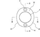
図1〜図3には本発明の連結構造の一例を示す。図1は連結された車両排気管の横断面図であり、図2、図3はそれぞれ、図1のII−II線およびIII−III線に沿った縦断面図である。図2,図3において、上流側排気管1と下流側排気管2が開口縁11,21を対向させて位置させられている。各排気管1,2は例えば1.2〜1.5mmの肉厚であり、その開口縁11,21は拡開成形によって径方向外方へ屈曲させられた後、さらに径方向内方へ折り返されて、開口周囲に所定幅のフランジ部12,22が形成されている。フランジ部12,22はこれらの間にガスケット31を介設して互いに衝合され、径方向対称位置(図1)でボルト41とナット42によって結合されている。このようにして、両排気管1,2が連結されている。なお、ボルト貫通部を除くフランジ部12,22の外周縁はさらに7〜8mmの高さで略直角に折り曲げられて(図3)強化リブ13,23としてあり、これによりガスケット31の面圧が確保されるようになっている。
(First embodiment)
1 to 3 show an example of the connection structure of the present invention. FIG. 1 is a transverse sectional view of connected vehicle exhaust pipes, and FIGS. 2 and 3 are longitudinal sectional views taken along lines II-II and III-III in FIG. 1, respectively. 2 and 3, the upstream
本実施形態によれば、従来のように溶接による固定部が無いため、応力集中によるひび割れ破損等を生じることがない上に、溶接工程に手間を要することもない。また、ガス漏れ防止の面圧確保のために厚肉の連結用フランジを使用する必要が無いから、重量とコストの増大が避けられる。さらにフランジ部12,22を排気管の開口縁に一体に形成しているから、別体の連結用フランジ61,62(図8)を使用した従来構造に比して部品点数を削減することができる。
According to the present embodiment, since there is no fixed portion by welding as in the prior art, crack damage or the like due to stress concentration does not occur, and no labor is required for the welding process. Further, since it is not necessary to use a thick connecting flange for securing a surface pressure for preventing gas leakage, an increase in weight and cost can be avoided. Further, since the
(第2実施形態)
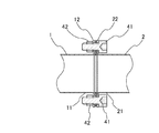
図4〜図6には本発明の連結構造の他の例を示す。図4は連結された車両排気管の横断面図であり、図5、図6はそれぞれ、図4のV−V線およびVI−VI線に沿った縦断面図である。本実施形態においても、開口縁11,21(図5、図6)を対向させて位置させられた上流側排気管1と下流側排気管2は例えば1.2〜1.5mmの肉厚で、上記開口縁11,21は拡開成形によって径方向外方へ屈曲させられた後、径方向内方へ折り返されて、開口周囲に所定幅のフランジ部14,24が形成されている。フランジ部14,24はこれらの間に大径のガスケット32を介設して互いに衝合されている。ガスケット32の外周部はフランジ部14,24の外周から径方向外方へ突出しており、このガスケット32の外周部に、各排気管の外周に移動可能に嵌装された挟持リング5A,5Bが両面から当接している。なお、本実施形態におけるフランジ部14,24は第1実施形態のものよりも小幅とできるから、拡開成形時の成形負担を軽減することができる。
(Second Embodiment)
4 to 6 show other examples of the connection structure of the present invention. 4 is a cross-sectional view of connected vehicle exhaust pipes, and FIGS. 5 and 6 are vertical cross-sectional views taken along lines VV and VI-VI in FIG. 4, respectively. Also in the present embodiment, the upstream
挟持リング5A,5Bは内周部51が、各排気管1,2のフランジ部14,24の対向方向外方の側面に沿った湾曲断面に成形されて、上記側面に当接している。挟持リング5A,5Bの外周部はガスケット32の外周部を挟んで対向し、径方向対称位置(図4)でボルト41とナット42によって結合されている。このようにして、両排気管1,2が連結されている。なお、ボルト貫通部を除く挟持リング5A,5Bの外周縁はさらに7〜8mmの高さで略直角に折り曲げられて(図6)強化リブ52としてあり、これによりガスケット32の面圧が確保されるようになっている。
The inner
本実施形態によっても、従来のように溶接による固定部が無いため、応力集中によるひび割れ破損等を生じることがない上に、溶接工程に手間を要することもない。また、ガス漏れ防止の面圧確保のために厚肉の連結用フランジを使用する必要が無いから、重量とコストの増大が避けられる。さらに、フランジ部14,24を排気管の開口縁に一体に形成しているから、別体の係止リング71,72(図14)を使用した従来構造に比して部品点数を削減することができる。
Also according to this embodiment, since there is no fixed portion by welding as in the prior art, crack damage due to stress concentration does not occur, and the welding process does not require labor. Further, since it is not necessary to use a thick connecting flange for securing a surface pressure for preventing gas leakage, an increase in weight and cost can be avoided. Furthermore, since the
(第3実施形態)
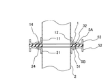
排気管の開口周囲にフランジ部を形成する他の方法を図7に示す。図7(1)の三角印で示す管体8の外周を適当な手段でクランプし固定した状態で、開口81から所定長離れた中間位置の管壁全周をビーディング加工によって外方へ略山形断面に拡径させて膨出部82とする。このように、開口81から離れた中間位置の管壁を膨出させているため、拡径に伴って開口81との間の管壁材が膨出部82へ供給されて、膨出部82の肉厚が過度に薄くなるのが防止される。この後、膨出部82の山形断面の、開口81側裾部で管体8を切断して新たな開口83を形成し(図7(2))、膨出部82の山形断面の頂部を境に開口側斜面821を他方の斜面822に押し付けるようにプレス成形で押し潰して(図7(3))、開口83周囲に起立するフランジ部84とする。
(Third embodiment)
FIG. 7 shows another method for forming the flange portion around the opening of the exhaust pipe. In a state where the outer periphery of the
(第4実施形態)
排気管の開口周囲にフランジ部を形成するさらに他の方法を図8に示す。図8(1)の三角印で示す管体7の外周を適当な手段でクランプし固定した状態で、開口81から所定長離れた管体8内の中間位置へ複数分割されたパンチPTを挿入する。そして、プランジャPLを前進させて各パンチPTを開くことによってバルジ加工を行い、管壁全周を外方へ略山形断面に拡径させて膨出部82とする。この後、膨出部82の山形断面の、開口81側裾部で管体8を切断して新たな開口83を形成し(図8(2))、膨出部82の山形断面の頂部を境に開口側斜面821を他方の斜面822に押し付けるようにプレス成形で押し潰して(図8(3))、開口83周囲に起立するフランジ部84を形成する。このような方法によっても第3実施形態の方法と同様に膨出部82が過度に薄肉になるのを防止することができる。なお、バルジ加工を液圧バルジで行っても良い。
(Fourth embodiment)
FIG. 8 shows still another method for forming the flange portion around the opening of the exhaust pipe. In the state where the outer periphery of the tube 7 indicated by the triangle mark in FIG. 8A is clamped and fixed by an appropriate means, a plurality of divided punches PT are inserted into an intermediate position in the
(第5実施形態)
排気管の開口周囲にフランジ部を形成するさらに他の方法を図9に示す。最初に金属板体10を図9(1)に示すように略U字断面形にプレス加工する。この際、一方の端面101から所定長離れた中間位置において板面を外方へ略山形断面をなすように変形させて膨出部92としておく。この後、板体10を筒状にプレス成形して(図9(2))、長手方向へ延びる衝合端923を溶接接合し、開口91から所定長離れた中間位置に膨出部92を有する管体9とする。なお、この場合の溶接は同種金属同士のものであるから電食は生じない。この後、膨出部92の山形断面の、開口側裾部で管体9を切断して新たな開口93を形成し(図9(3))、膨出部92の山形断面の頂部を境に開口側斜面921を他方の斜面922に押し付けるようにプレス成形で押し潰して(図9(4))、起立するフランジ部94を開口93の周囲に形成する。本実施形態はフランジ部を備えた大径の排気管の製造に適している。
(Fifth embodiment)
FIG. 9 shows still another method for forming the flange portion around the opening of the exhaust pipe. First, the
(第6実施形態)
排気管の開口周囲にフランジ部を形成するさらに他の方法を図10に示す。金属板体10を図10(1)に示すように略U字断面形にプレス加工し、この際、一方の端面101から所定長離れた中間位置において、隣接する長手方向の二箇所で板面を外方へ略山形断面をなすように膨出変形させて膨出部92A,92Bとしておく。この後、板体10を筒状にプレス成形して(図10(2))、長手方向へ延びる衝合端923を溶接接合し、開口91から所定長離れた中間位置に互いに隣接する二つの膨出部92A,92Bを有する管体9とする。この後、開口91側に位置する膨出部92Aの山形断面の、開口側裾部で管体9を切断して新たな開口93を形成し(図10(3))、各膨出部92A,92Bの山形断面の頂部を境に開口側斜面921を他方の斜面922に押し付けるようにプレス成形で押し潰して(図10(4))、起立するフランジ部94を開口93の周囲に形成する。本実施形態はフランジ部を備えた大径の排気管の製造に適するとともに、フランジ部94の厚みを十分に確保することができる。なお、膨出部を3つ以上形成して、これらを押し潰してフランジ部を形成するようにすればさらにその厚みを確保することができる。
(Sixth embodiment)
FIG. 10 shows still another method for forming the flange portion around the opening of the exhaust pipe. The
(その他の実施形態)
上記各実施形態において、フランジ部12,22の強度が十分確保できれば、径方向内方への折り返しや強化リブ13,23の形成は不要である。また、挟持リング5A,5Bの強度が十分確保できれば、強化リブ52の形成は不要である。
(Other embodiments)
In each of the above embodiments, if the strength of the
1…上流側排気管、11…開口縁、12,14…フランジ部、2…下流側排気管、21…開口縁、22,24…フランジ部、41…ボルト、42…ナット、5A,5B…挟持リング、8…管体、81…開口、82…膨出部、821,822…斜面、84…フランジ部、9…管体、91…開口、92,92A,92B…膨出部、921,922…斜面、94…フランジ部。
DESCRIPTION OF
Claims (3)
Priority Applications (7)
| Application Number | Priority Date | Filing Date | Title |
|---|---|---|---|
| JP2005213725A JP2006233953A (en) | 2005-01-27 | 2005-07-25 | Connection structure for vehicular exhaust pipe |
| KR1020050130386A KR100795133B1 (en) | 2005-01-27 | 2005-12-27 | Construction of coupling exhaust pipes of vehicle |
| US11/334,403 US20060162326A1 (en) | 2005-01-27 | 2006-01-19 | Construction of coupling exhaust pipes of vehicle |
| AT06001555T ATE403074T1 (en) | 2005-01-27 | 2006-01-25 | COUPLING DEVICE FOR EXHAUST PIPES OF A VEHICLE |
| DE602006001959T DE602006001959D1 (en) | 2005-01-27 | 2006-01-25 | Coupling device for exhaust pipes of a vehicle |
| EP06001555A EP1686248B1 (en) | 2005-01-27 | 2006-01-25 | Construction of coupling exhaust pipes of vehicle |
| HK07100688.0A HK1094019A1 (en) | 2005-01-27 | 2007-01-19 | Construction of coupling exhaust pipes of vehicle |
Applications Claiming Priority (2)
| Application Number | Priority Date | Filing Date | Title |
|---|---|---|---|
| JP2005019306 | 2005-01-27 | ||
| JP2005213725A JP2006233953A (en) | 2005-01-27 | 2005-07-25 | Connection structure for vehicular exhaust pipe |
Publications (1)
| Publication Number | Publication Date |
|---|---|
| JP2006233953A true JP2006233953A (en) | 2006-09-07 |
Family
ID=36105383
Family Applications (1)
| Application Number | Title | Priority Date | Filing Date |
|---|---|---|---|
| JP2005213725A Pending JP2006233953A (en) | 2005-01-27 | 2005-07-25 | Connection structure for vehicular exhaust pipe |
Country Status (7)
| Country | Link |
|---|---|
| US (1) | US20060162326A1 (en) |
| EP (1) | EP1686248B1 (en) |
| JP (1) | JP2006233953A (en) |
| KR (1) | KR100795133B1 (en) |
| AT (1) | ATE403074T1 (en) |
| DE (1) | DE602006001959D1 (en) |
| HK (1) | HK1094019A1 (en) |
Families Citing this family (8)
| Publication number | Priority date | Publication date | Assignee | Title |
|---|---|---|---|---|
| US8662544B2 (en) * | 2010-05-05 | 2014-03-04 | Metal Textiles Corporation | Pipe joint and seal with band clamp |
| US8533952B2 (en) | 2010-12-22 | 2013-09-17 | Nakagawa Sangyo Co., Ltd. | Pipe flange forming method |
| DE102011004243B4 (en) * | 2011-02-16 | 2015-02-19 | Eberspächer Exhaust Technology GmbH & Co. KG | exhaust manifold |
| FR2974878A1 (en) * | 2011-05-05 | 2012-11-09 | Caillau Ets | TIGHTENING NECKLACE WITH HINGE |
| US10287990B2 (en) | 2014-08-08 | 2019-05-14 | Rohr, Inc. | Bleed system bolted duct with recessed seals |
| USD749708S1 (en) * | 2015-02-12 | 2016-02-16 | Steven A Smith | Pipe joint seal with annular reinforcement ridge |
| USD753802S1 (en) * | 2015-02-12 | 2016-04-12 | Steven A Smith | Pipe joint replacement seal with annular reinforcement ridge |
| USD755941S1 (en) * | 2015-02-12 | 2016-05-10 | Steven A Smith | Pipe joint replacement seal with handle |
Citations (3)
| Publication number | Priority date | Publication date | Assignee | Title |
|---|---|---|---|---|
| JPS50151755A (en) * | 1974-05-29 | 1975-12-05 | ||
| JPS6081223U (en) * | 1983-11-09 | 1985-06-05 | マツダ株式会社 | Engine exhaust pipe connection structure |
| JPH0437831U (en) * | 1990-07-30 | 1992-03-31 |
Family Cites Families (13)
| Publication number | Priority date | Publication date | Assignee | Title |
|---|---|---|---|---|
| US33275A (en) * | 1861-09-10 | Improved pipe-joi-nt | ||
| DE102C (en) * | 1877-07-17 | R. GOTTHEIL, Civil-Ingenieur, in Berlin | Method of cooling the glass | |
| US682026A (en) * | 1901-05-11 | 1901-09-03 | Rudolf Bungeroth | Wrought-metal pipe. |
| GB191110120A (en) * | 1911-04-26 | 1912-02-15 | Franz Albert | Improvements in Pipe Couplings. |
| US1065892A (en) * | 1911-05-26 | 1913-06-24 | Franz Albert | Pipe-joint. |
| DE868542C (en) * | 1941-02-09 | 1953-02-26 | Westdeutsche Mannesmannroehren | Socket pipe connection |
| NL6814028A (en) * | 1967-11-09 | 1969-05-13 | ||
| JP3112118B2 (en) * | 1992-05-18 | 2000-11-27 | 日本ピラー工業株式会社 | Spiral gaskets for automotive exhaust systems |
| US6540266B2 (en) * | 2000-06-19 | 2003-04-01 | Macdonald-Miller Inc. | Spin forming a tubular workpiece to form a radial flange on a tubular flange and a thick rim on the radial flange |
| US6508491B1 (en) * | 2000-11-09 | 2003-01-21 | Guenther Ebinger | Exhaust manifold clamp with vibration disconnecting effects for flange connections in exhaust lines and method of making same |
| US6412519B1 (en) * | 2001-01-24 | 2002-07-02 | Met-Coil Systems Corporation | Duct connecting system having double walled transverse flanges |
| JP3652609B2 (en) | 2001-02-05 | 2005-05-25 | 藤壷技研工業株式会社 | Exhaust pipe connection method |
| DE10204261A1 (en) * | 2002-02-02 | 2003-08-07 | Bauer Christian Gmbh & Co | Flange connection of two pipes, in particular the pipes of an exhaust system of a motor vehicle internal combustion engine |
-
2005
- 2005-07-25 JP JP2005213725A patent/JP2006233953A/en active Pending
- 2005-12-27 KR KR1020050130386A patent/KR100795133B1/en active IP Right Grant
-
2006
- 2006-01-19 US US11/334,403 patent/US20060162326A1/en not_active Abandoned
- 2006-01-25 EP EP06001555A patent/EP1686248B1/en active Active
- 2006-01-25 DE DE602006001959T patent/DE602006001959D1/en active Active
- 2006-01-25 AT AT06001555T patent/ATE403074T1/en not_active IP Right Cessation
-
2007
- 2007-01-19 HK HK07100688.0A patent/HK1094019A1/en unknown
Patent Citations (3)
| Publication number | Priority date | Publication date | Assignee | Title |
|---|---|---|---|---|
| JPS50151755A (en) * | 1974-05-29 | 1975-12-05 | ||
| JPS6081223U (en) * | 1983-11-09 | 1985-06-05 | マツダ株式会社 | Engine exhaust pipe connection structure |
| JPH0437831U (en) * | 1990-07-30 | 1992-03-31 |
Also Published As
| Publication number | Publication date |
|---|---|
| US20060162326A1 (en) | 2006-07-27 |
| KR100795133B1 (en) | 2008-01-17 |
| KR20060086836A (en) | 2006-08-01 |
| HK1094019A1 (en) | 2007-03-16 |
| EP1686248B1 (en) | 2008-07-30 |
| ATE403074T1 (en) | 2008-08-15 |
| EP1686248A1 (en) | 2006-08-02 |
| DE602006001959D1 (en) | 2008-09-11 |
Similar Documents
| Publication | Publication Date | Title |
|---|---|---|
| JP2006233953A (en) | Connection structure for vehicular exhaust pipe | |
| US4372017A (en) | U-Bolt exhaust system clamp with double saddle | |
| US6796004B2 (en) | Exhaust system clamp | |
| US5114191A (en) | Pipe fitting with coupling body and improved isolation tooth arrangement | |
| KR20080014734A (en) | Pipe clamp assembly with v-ring insert | |
| US8628122B2 (en) | Pipe compression joint | |
| JPH09509729A (en) | Pipe lap joint with improved crushable seal area | |
| US10233815B2 (en) | Muffler joint | |
| US4393559A (en) | U-Bolt clamp with tubular reinforcing means | |
| JPS62242193A (en) | Clamping ring | |
| JP2003314766A (en) | Butt joint between two pipe material made of sheet metal, and method for forming joint flange of butt joint | |
| US3605214A (en) | Clamp for tubing | |
| TWI437179B (en) | Assembly for a claw collar, corresponding claw collar and tubular connection | |
| JPS5840076B2 (en) | Airtight ring clamp for pipe slip joints | |
| US4265005A (en) | U-Bolt clamp saddle construction | |
| JP2007239537A (en) | Exhaust pipe flange joint structure | |
| CN100447384C (en) | Construction of coupling exhaust pipes of vehicle | |
| US11951521B2 (en) | Method of manufacturing connection member | |
| JP4759868B2 (en) | UOE pipe O-press mold and UOE pipe manufacturing method | |
| JP4761940B2 (en) | Detachment prevention fitting | |
| US3192593A (en) | Clamp for tubing | |
| JP4473705B2 (en) | Hydroform processing method, hydroform molded article and structure | |
| JP2008019882A (en) | Joint structure of pipe | |
| CN215635551U (en) | Pipeline equipment | |
| WO2020208994A1 (en) | Tube end member, flange tube, band joint structure for flange tube, and method for manufacturing tube end member |
Legal Events
| Date | Code | Title | Description |
|---|---|---|---|
| A621 | Written request for application examination |
Free format text: JAPANESE INTERMEDIATE CODE: A621 Effective date: 20080611 |
|
| A977 | Report on retrieval |
Free format text: JAPANESE INTERMEDIATE CODE: A971007 Effective date: 20100609 |
|
| A131 | Notification of reasons for refusal |
Free format text: JAPANESE INTERMEDIATE CODE: A131 Effective date: 20100615 |
|
| A02 | Decision of refusal |
Free format text: JAPANESE INTERMEDIATE CODE: A02 Effective date: 20101102 |