JP2006219246A - Hook position detecting device of movable crane - Google Patents
Hook position detecting device of movable crane Download PDFInfo
- Publication number
- JP2006219246A JP2006219246A JP2005033294A JP2005033294A JP2006219246A JP 2006219246 A JP2006219246 A JP 2006219246A JP 2005033294 A JP2005033294 A JP 2005033294A JP 2005033294 A JP2005033294 A JP 2005033294A JP 2006219246 A JP2006219246 A JP 2006219246A
- Authority
- JP
- Japan
- Prior art keywords
- hook
- tip
- boom
- jib
- laser
- Prior art date
- Legal status (The legal status is an assumption and is not a legal conclusion. Google has not performed a legal analysis and makes no representation as to the accuracy of the status listed.)
- Pending
Links
Images


Abstract
Description
本発明は、移動式クレーンのフック位置検出装置に関するものである。 The present invention relates to a hook position detection device for a mobile crane.
移動式クレーンがクレーン作業を行う時には、ブーム先端又はジブ先端から吊下げたフック位置の正確な把握が重要である。建物に近接して移動式クレーンを設置した状態での屋上への荷揚げ作業あるいは地下への積み下ろし作業などでは、クレーン運転室から直接フックを目視することができないため、積み下ろし位置で作業指示を行う玉掛け作業者からの無線連絡に頼ってクレーンオペレータがクレーン操作しているのが現状である。この場合でも、フック位置検出装置によりクレーンオペレータが直接フック位置を把握することができれば、クレーン作業の効率化及び安全性向上を図ることができる。また、クレーン作業の自動化あるいはフックの振れ止め制御においても、フック位置の検出は重要な技術要素である。 When a mobile crane performs a crane operation, it is important to accurately grasp the position of a hook suspended from the tip of a boom or jib. When unloading work to the rooftop or loading / unloading work underground with a mobile crane installed close to the building, hooks cannot be seen directly from the crane cab. The current situation is that the crane operator operates the crane by relying on wireless communication from the worker. Even in this case, if the crane operator can directly grasp the hook position by the hook position detection device, it is possible to improve the efficiency and safety of the crane work. In addition, detection of the hook position is an important technical element also in automation of crane work or hook steadying control.
移動式クレーンに用いられるフック位置検出装置として、例えば特許文献1に記載された装置が知られている。特許文献1の制御装置は、ウインチドラムに取り付けられたドラム回転検出器からの検出回転量、伸縮ブームのブーム長検出器からの検出ブーム長、および伸縮ブームのブーム起仰角度検出器からの検出ブーム起仰角度を演算部に入力し、フックの地上高さを、ドラムの回転量、ブーム長、およびブーム起伏角度の関数として算出する演算部とから構成されている。
ところが、上記従来のフック位置検出装置はフック位置を検出するセンサとして、従来からクレーンに使用されるドラム回転検出器、ブーム長検出器、およびブーム起仰角度検出器を用い、それらが検出した回転量、ブーム長及びブーム起仰角度に基づき演算部がフック位置を演算するものであったため、その検出精度を高めようとしても限界があった。また、近年の軽量化の要請に基づき高張力鋼を用いたブームあるいはジブでは、クレーン作業時のブームあるいはジブのたわみ変形が大きいため、フック位置を高精度に検出することが困難となっていた。 However, the conventional hook position detecting device uses a drum rotation detector, a boom length detector, and a boom elevation angle detector that are conventionally used in cranes as sensors for detecting the hook position. Since the calculation unit calculates the hook position based on the amount, the boom length, and the boom elevation angle, there is a limit even if it is attempted to increase the detection accuracy. In addition, booms or jibs using high-tensile steel based on recent demands for weight reduction have been difficult to detect the hook position with high accuracy due to large deformation of the boom or jib during crane work. .
そこで、本発明は、対象物の高精度な位置検出が可能なGPS装置、レーザー測距装置あるいは、レーザー測距追尾装置を使用することにより、従来よりも精度の高いフックの3次元位置を検出できる移動式クレーンのフック位置検出装置を提供しようとするものである。 Therefore, the present invention detects the three-dimensional position of the hook with higher accuracy than before by using a GPS device, a laser range finder, or a laser range finder that can detect the position of an object with high accuracy. It is an object of the present invention to provide a movable crane hook position detection device.
本願の請求項1に記載された移動式クレーンのフック位置検出装置は、走行車体に旋回自在に旋回台を搭載し、当該旋回台に伸縮自在なブームを起伏自在に枢着し、当該ブーム先端にジブを脱着可能とし、装備したウインチによりブーム先端又はジブ先端から吊下するフックを巻上下げ自在とした移動式クレーンのフック位置検出装置であって、前記ブーム先端又はジブ先端に配置されブーム先端又はジブ先端の対地3次元位置を検出するGPS装置と、前記ブーム先端又はジブ先端に配置され前記フックにレーザービームを照射し、反射ビームによりフックまでの距離を検出するレーザー測距装置と、を備え、前記GPS装置とレーザー測距装置とからの信号により、前記フックの対地3次元位置を演算することを特徴とする。 According to a first aspect of the present invention, there is provided a mobile crane hook position detection device, wherein a swivel is mounted on a traveling vehicle body so that a swivel can be swung freely, and a telescopic boom is pivotally mounted on the swivel. A hook position detection device for a mobile crane that allows a jib to be attached to and detached from a boom tip or a jib tip by means of a equipped winch, and is arranged at the boom tip or jib tip. A GPS device that detects a three-dimensional position of the tip or jib tip to the ground, a laser distance measuring device that is disposed at the tip of the boom or jib tip, irradiates the hook with a laser beam, and detects the distance to the hook by a reflected beam; And calculating the three-dimensional position of the hook to the ground based on signals from the GPS device and the laser distance measuring device.
本願の請求項2に記載された移動式クレーンのフック位置検出装置は、走行車体に旋回自在に旋回台を搭載し、当該旋回台に伸縮自在なブームを起伏自在に枢着し、当該ブーム先端にジブを脱着可能とし、装備したウインチによりブーム先端又はジブ先端から吊下するフックを巻上下げ自在とした移動式クレーンのフック位置検出装置であって、前記ブーム先端又はジブ先端に配置されブーム先端又はジブ先端の対地3次元位置を検出するGPS装置と、前記ブーム先端又はジブ先端に配置され前記フックにレーザービームを照射し、反射ビームによりフックまでの距離と方向を検出するレーザー測距追尾装置と、を備え、 前記GPS装置とレーザー測距追尾装置とからの信号により、前記フックの対地3次元位置を演算することを特徴とする。 According to a second aspect of the present invention, there is provided a mobile crane hook position detection device comprising: a swivel mounted on a traveling vehicle body so that the swivel is freely pivotable; A hook position detection device for a mobile crane that allows a jib to be attached to and detached from a boom tip or a jib tip by means of a equipped winch, and is arranged at the boom tip or jib tip. A GPS device that detects the three-dimensional position of the tip or the jib tip to the ground, and a laser distance tracking that is arranged at the tip of the boom or the tip of the jib, irradiates the hook with a laser beam, and detects the distance and direction to the hook by a reflected beam And a three-dimensional position of the hook to the ground is calculated based on signals from the GPS device and the laser ranging device. That.
本願の請求項3に記載された移動式クレーンのフック位置検出装置は、走行車体に旋回自在に旋回台を搭載し、当該旋回台に伸縮自在なブームを起伏自在に枢着し、当該ブーム先端にジブを脱着可能とし、装備したウインチによりブーム先端又はジブ先端から吊下するフックを巻上下げ自在とした移動式クレーンのフック位置検出装置であって、前記走行車体に配置され前記ブーム先端又はジブ先端にレーザービームを照射し、反射ビームによりブーム先端又はジブ先端までの距離と方向を検出するレーザー測距追尾装置と、前記ブーム先端又はジブ先端に配置され前記フックにレーザービームを照射し、反射ビームによりフックまでの距離を検出するレーザー測距装置と、を備え、前記レーザー測距追尾装置とレーザー測距装置とからの信号により、前記フックの走行車体に対する3次元位置を演算することを特徴とする。 According to a third aspect of the present invention, there is provided a mobile crane hook position detection device comprising a swivel mounted on a traveling vehicle body so that the swivel can be swung freely, and a retractable boom pivotably mounted on the swivel. And a hook position detecting device for a mobile crane in which a boom suspended from a boom tip or a jib tip can be hoisted and lowered by an equipped winch, and disposed on the traveling vehicle body, A laser ranging tracking device that irradiates a laser beam to the tip of the jib and detects the distance and direction to the tip of the boom or the tip of the jib by a reflected beam, and irradiates the hook with the laser beam arranged at the tip of the boom or the tip of the jib, A laser range finder that detects the distance to the hook by a reflected beam, and a signal from the laser range finder and the laser range finder. Accordingly, characterized by calculating the 3-dimensional position relative to the vehicle body of the hook.
本願の請求項4に記載された移動式クレーンのフック位置検出装置は、走行車体に旋回自在に旋回台を搭載し、当該旋回台に伸縮自在なブームを起伏自在に枢着し、当該ブーム先端にジブを脱着可能とし、装備したウインチによりブーム先端又はジブ先端から吊下するフックを巻上下げ自在とした移動式クレーンのフック位置検出装置であって、前記走行車体に配置され前記ブーム先端又はジブ先端にレーザービームを照射し、反射ビームによりブーム先端又はジブ先端までの距離と方向を検出する第1レーザー測距追尾装置と、 前記ブーム先端又はジブ先端に配置され前記フックにレーザービームを照射し、反射ビームによりフックまでの距離と方向を検出する第2レーザー測距追尾装置と、を備え、前記第1レーザー測距追尾装置と第2レーザー測距追尾装置とからの信号により、前記フックの走行車体に対する3次元位置を演算することを特徴とする。 According to a fourth aspect of the present invention, there is provided a mobile crane hook position detection device including a swivel base mounted on a traveling vehicle body, a retractable boom pivotally mounted on the swivel base, and a boom tip. And a hook position detecting device for a mobile crane in which a boom suspended from a boom tip or a jib tip can be hoisted and lowered by an equipped winch, and disposed on the traveling vehicle body, A first laser ranging tracking device that irradiates a laser beam to the tip of the jib and detects the distance and direction to the tip of the boom or the tip of the jib by a reflected beam, and irradiates the hook with the laser beam disposed at the tip of the boom or the jib And a second laser ranging tracking device that detects the distance and direction to the hook by the reflected beam, and the first laser ranging tracking device and the second laser ranging tracking device. The signal from the Za ranging tracking device, characterized by calculating the 3-dimensional position relative to the vehicle body of the hook.
請求項1に記載した移動式クレーンのフック位置検出装置では、ブーム先端に配置したGPS装置によって移動式クレーンのブーム先端の対地3次元位置を検出するようにするとともに、ブーム先端に配置したレーザー測距装置によってブーム先端からフックまでの距離を検出するようにした。そして、上記ブーム先端の対地3次元位置とブーム先端からフックまでの距離とからフックの対地3次元位置を演算するようにしたので、極めて高精度なフックの対地3次元位置の検出が可能となる。
In the mobile crane hook position detection device according to
請求項2に記載した移動式クレーンのフック位置検出装置では、ブーム先端に配置したGPS装置によって各移動式クレーンのブーム先端の対地3次元位置を検出するようにするとともに、ブーム先端に配置したレーザー測距追尾装置によってブーム先端からフックまでの距離と方向を検出するようにした。そして、上記ブーム先端の対地3次元位置とブーム先端からフックまでの距離と方向とからフックの対地3次元位置を演算するようにしたので、極めて高精度なフック対地3次元位置の検出が可能となる。
In the mobile crane hook position detection device according to
請求項3に記載した移動式クレーンのフック位置検出装置では、走行車体に配置したレーザー測距追尾装置によって走行車体に対するブーム先端位置を検出するようにすると共に、ブーム先端に配置したレーザー測距装置によってブーム先端からフックまでの距離を検出するようにした。そして、上記走行車体に対するブーム先端の3次元位置とブーム先端からフックまでの距離とからフックの走行車体に対する3次元位置を演算するようにしたので、極めて高精度な走行車体に対するフック3次元位置の検出が可能となる。 In the hook position detecting device for a mobile crane according to claim 3, the position of the boom tip with respect to the traveling vehicle body is detected by the laser distance measuring and tracking device arranged on the traveling vehicle body, and the laser distance measuring device arranged at the tip of the boom. To detect the distance from the tip of the boom to the hook. Since the three-dimensional position of the hook with respect to the traveling vehicle body is calculated from the three-dimensional position of the boom tip with respect to the traveling vehicle body and the distance from the boom tip to the hook, the three-dimensional position of the hook with respect to the traveling vehicle body with extremely high accuracy is calculated. Detection is possible.
請求項4に記載した移動式クレーンのフック位置検出装置では、走行車体に配置した第1レーザー測距追尾装置によって走行車体に対するブーム先端位置を検出するようにすると共に、ブーム先端に配置した第2レーザー測距追尾装置によってブーム先端からフックまでの距離と方向を検出するようにした。そして、上記走行車体に対するブーム先端の3次元位置とブーム先端からフックまでの距離と方向からフックの走行車体に対する3次元位置を演算するようにしたので、極めて高精度な走行車体に対するフック3次元位置の検出が可能となる。 In the mobile crane hook position detection device according to claim 4, the boom tip position relative to the traveling vehicle body is detected by the first laser ranging tracking device disposed on the traveling vehicle body, and the second is disposed at the boom distal end. The distance and direction from the boom tip to the hook were detected by a laser ranging tracking device. The three-dimensional position of the hook relative to the traveling vehicle body is calculated from the three-dimensional position of the boom tip relative to the traveling vehicle body and the distance and direction from the boom tip to the hook. Can be detected.
移動式クレーンとしてラフテレーンクレーン11に本願発明を適用した実施例を説明する。
An embodiment in which the present invention is applied to a
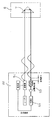
図1に示すラフテレーンクレーン11は、アウトリガ1を備えた走行車体2に旋回自在に旋回台3を搭載している。旋回台3には伸縮自在なブーム4を起伏自在に枢着している。ラフテレーンクレーン11にはウインチが装備されており、ブーム先端5から吊下するフック6を巻上下げ自在に操作できるようになっている。
A
20はラフテレーンクレーン11に搭載されるフック位置検出装置である。21はブーム先端5の対地3次元位置を検出するGPS装置である。22は、前記ブーム先端5に配置され前記フック6に配置された反射鏡7にレーザービーム8を照射し、反射ビームによりフック6までの距離を検出するレーザー測距装置である。23は、前記GPS装置21とレーザー測距装置22とからの信号により、前記フック6の対地3次元位置を演算する演算手段である。以下、フック位置検出装置20の各構成を詳述する。
GPS装置21は、人工衛星からの電波を受信することによって世界中のどこにいても自分自身の位置を知ることができるシステムであり、現在既に開発されて船や自動車等の移動体の位置を高精度に測定するナビゲーションシステムや工事測量等に応用されている。
The
本実施例1においては、GPS装置21の一組のアンテナ24およびレシーバ25が地表面の任意の位置に既知の基準点として設置されるとともに、他のもう一組のアンテナ26およびレシーバ27がブーム先端5に設置される。すなわち、図1に示したように敷地内アンテナ24がクレーン作業敷地内の任意の位置に既知の基準点として設置されているとともに、この敷地内基準点アンテナ24に接続されているレシーバ25が隣接して配備されている。また、ブーム先端5にGPSアンテナ26が配置されているとともに、クレーンの運転室にGPSアンテナ26に接続されているレシーバ27が配備されている。
In the first embodiment, a pair of
両方のレシーバ25、27には現在の時刻が格納されていて、両レシーバ25,27はこの現在時刻を基に現在飛んでいるすべての人工衛星の位置を知ることができるようになっている。すなわち、敷地内基準アンテナ24が、複数個(例えば5個等)の人工衛星28(図1では1個しか図示されていない)からの電波を随時受けてレシーバ25に送信し、レシーバ25は既知の基準点位置の経度X0、緯度Y0、高さZ0を知ることができるようになっている。また、GPSアンテナ26が複数個(例えば5個等)の人工衛星28(図1では1個しか図示されていない)からの電波を随時受けてレシーバ27に送信し、レシーバ27はGPSアンテナ26からの信号に基づいてブーム先端5の位置の経度X1、緯度Y1、高さZ1を知ることができるようになっている。
Both
既知の基準点の経度X0、緯度Y0、高さZ0のデータが敷地内基準点アンテナ24から無線でGPSアンテナ26に出力され、更にGPSアンテナ26からレシーバ27に送信される。レシーバ27は、GPSアンテナ26が受信した人工衛星28からの電波に基づいて得たブーム先端5の経度X1、緯度Y1、高さZ1のデータを既知の基準点の経度X0、緯度Y0、高さZ0のデータにより補正して、地表面上におけるブーム先端5の位置の経度X、緯度Y、高さZの正確なデータを得ることができるようになっている。
The data of the known reference point longitude X0, latitude Y0, and height Z0 are wirelessly output from the in-site
図2はレーザー測距装置22の説明図である。図2に示したレーザー測距装置22は「レーザー光の振幅(または偏向)変調を利用し基準波形と戻ってきた波形の位相のずれを測定することによって距離を求める方法」が使用されている。レーザー光を変調器51により周波数fで振幅変調させ、フック6に設置した反射板7に向けて照射する。反射板7から反射されたレーザー光を光電検出器53で受ける。レーザー光が反射板7まで往復する時間があるので、戻ってきたレーザー光の変調の位相は送信光とは異なっている。この位相差Φを位相計54で計測することによりブーム先端5とフック6との距離Lを求めるようになっている。なお、上記反射板7をフック6に設置せずに吊荷40に直接設置するようにしてもよい。この場合は、ブーム先端5と吊荷40との距離を直接求めることができる。
FIG. 2 is an explanatory diagram of the laser
上述したGPS装置21が得たブーム先端5の位置データと、レーザー測距装置22が求めたブーム先端5とフック6との距離データは演算手段23に送られ、演算手段23は両データからフック6の対地3次元位置(経度X、緯度Y、高さZ−L)を演算する。フック位置検出手段20の演算手段23と移動式クレーン制御装置33とはフック6の対地3次元位置信号等のクレーン制御に必要な信号を相互にやり取り可能に連絡されている。
The position data of the boom tip 5 obtained by the
上述したフック位置検出装置20によって、高精度なフックの対地3次元位置が演算されるため、クレーン操作及びクレーン制御においても高精度なフック3次元位置が利用できることとなる。したがって、たわみの大きなブームあるいはジブを持つ移動式クレーンであっても、正確なフック位置(又は吊荷位置)の把握と制御が可能となる。
Since the hook
図3は、実施例2の移動式クレーンのフック位置検出装置29である。実施例2のフック位置検出装置29は、上述した実施例1のフック位置検出装置20のブーム先端5に配置したレーザー測距装置22をレーザー測距追尾装置30とした点のみが相違する。
FIG. 3 shows a hook
レーザー測距追尾装置30の測距機能部分は、図2に図示し実施例1で説明したレーザー測距装置22と同じであるので説明を省略する。図4はレーザー測距追尾装置30の追尾機能部分60を説明するものである。光源として半導体レーザー61を使用し、レーザー光は、コリメートレンズ62、凹レンズ63、偏光ビームスプリッタ64、凸レンズ67通過した後に、レーザー光を発射する方向を偏光鏡65で制御し、フック6に当てる。装置から発射されたレーザー光は、フック6に取付けられた反射鏡7によって反射される。この反射レーザー光のうち装置に戻って凸レンズ67の径内にあるものが集光される。4分の1波長シート68によって偏光方向が90度回転しているため、偏光ビームスプリッタ64によって反射され、バンドパスフィルタ69を透過して4分割光検出器70の光検出面上に結像する。そこで、4分割光検出器70の各チャンネルからの光強度信号間の差を利用して、像の位置が4分割光検出器70の中心からどの程度離れているかを検出し、この像が常に中心位置へ来るようにガルバノスキャナー71へ制御信号を送る。ガルバノスキャナー71は電磁力で回転を得る一種のモーターで、これに偏光用の反射鏡65を取付けることで光の方向が制御できる。このような方式により、スキャナーの可動範囲で目標のフック6を追跡でき、スキャナー71の回転角からフック6の方向が分るようになっている。
The distance measuring function portion of the laser
上述した構成のフック位置検出装置29は、ブーム先端5に配置したレーザー測距追尾装置30がフック6までの距離のみならず、その方向をも検出することができる。そのため、吊荷40が振れているような場合、あるいは吊荷40が接地していて吊荷40とブーム先端5との位置がずれているような場合であっても、高精度なフック6の対地3次元位置を検出することができる。
The hook
図5は実施例3のフック位置検出装置80である。81は走行車体2に配置されブーム先端5に配置された反射板82にレーザービーム86を照射し、反射ビームによりブーム先端5までの距離と方向を検出するレーザー測距追尾装置である。レーザー測距追尾装置81は実施例2で説明したレーザー測距追尾装置30と同じものであるので、詳細な説明は省略する。22は、ブーム先端5に配置されフック6に配置された反射鏡7にレーザービーム8を照射し、反射ビームによりフック6までの距離を検出するレーザー測距装置である。85は、前記レーザー測距追尾装置81とレーザー測距装置22とからの信号により、前記フック6の走行車体2に対する3次元位置を演算する演算手段である。フック位置検出装置80の演算手段85と移動式クレーン制御装置93とはフック6の3次元位置信号等のクレーン制御に必要な信号を相互にやり取り可能に連絡されている。
FIG. 5 shows a hook
上述したフック位置検出装置80によって、高精度にフックの走行車体2に対する3次元位置が演算されるため、クレーン操作及びクレーン制御において高精度なフック3次元位置が利用できることとなる。したがって、たわみの大きなブームあるいはジブを持つ移動式クレーンであっても、正確なフック位置の把握と制御が可能となる。
Since the hook
図6は、実施例4の移動式クレーンのフック位置検出装置90である。実施例4のフック位置検出装置90は、上述した実施例3のフック位置検出装置80のブーム先端5に配置したレーザー測距装置22をレーザー測距追尾装置92とした点のみが相違する。
FIG. 6 shows a hook
上述した構成のフック位置検出装置90は、ブーム先端5に配置したレーザー測距追尾装置92がフック6までの距離のみならず、その方向をも検出することができる。そのため、吊荷40が振れているような場合あるいは吊荷40が接地していて吊荷40とブーム先端5との位置がずれているような場合であっても、高精度なフック6の走行車体2に対する3次元位置を検出することができる。
The hook
1:アウトリガ
2:走行車体
3:旋回台
4:ブーム
5:ブーム先端
6:フック
11:ラフテレーンクレーン
20、29、80、90:フック位置検出装置
21:GPS装置
22:レーザー測距装置
23、85:演算手段
30、81、92:レーザー測距追尾装置
1: Outrigger 2: Traveling vehicle body 3: Turntable 4: Boom 5: Boom tip 6: Hook 11:
Claims (4)
前記ブーム先端又はジブ先端に配置されブーム先端又はジブ先端の対地3次元位置を検出するGPS装置と、
前記ブーム先端又はジブ先端に配置され前記フックにレーザービームを照射し、反射ビームによりフックまでの距離を検出するレーザー測距装置と、を備え、
前記GPS装置とレーザー測距装置とからの信号により、前記フックの対地3次元位置を演算することを特徴とする移動式クレーンのフック位置検出装置。 A swivel is mounted on the vehicle body so that it can swivel. A telescopic boom can be pivotally mounted on the swivel, and the jib can be attached to and detached from the tip of the boom. A mobile crane hook position detection device that can freely hoist and lower the hook
A GPS device that is arranged at the boom tip or jib tip and detects the three-dimensional position of the boom tip or jib tip to the ground;
A laser range finder that is disposed at the tip of the boom or the tip of the jib, irradiates the hook with a laser beam, and detects the distance to the hook by a reflected beam, and
A hook position detecting device for a mobile crane, characterized in that a three-dimensional position of the hook to the ground is calculated based on signals from the GPS device and a laser distance measuring device.
前記ブーム先端又はジブ先端に配置されブーム先端又はジブ先端の対地3次元位置を検出するGPS装置と、
前記ブーム先端又はジブ先端に配置され前記フックにレーザービームを照射し、反射ビームによりフックまでの距離と方向を検出するレーザー測距追尾装置と、を備え、
前記GPS装置とレーザー測距追尾装置とからの信号により、前記フックの対地3次元位置を演算することを特徴とする移動式クレーンのフック位置検出装置。 A swivel is mounted on the vehicle body so that it can swivel. A telescopic boom can be pivotally mounted on the swivel, and the jib can be attached to and detached from the tip of the boom. A mobile crane hook position detection device that can freely hoist and lower the hook
A GPS device that is arranged at the boom tip or jib tip and detects the three-dimensional position of the boom tip or jib tip to the ground;
A laser ranging tracking device that is disposed at the boom tip or jib tip, irradiates the hook with a laser beam, and detects the distance and direction to the hook by a reflected beam;
A hook position detecting device for a mobile crane, characterized in that a three-dimensional position of the hook to the ground is calculated based on signals from the GPS device and a laser ranging tracking device.
前記走行車体に配置され前記ブーム先端又はジブ先端にレーザービームを照射し、反射ビームによりブーム先端又はジブ先端までの距離と方向を検出するレーザー測距追尾装置と、
前記ブーム先端又はジブ先端に配置され前記フックにレーザービームを照射し、反射ビームによりフックまでの距離を検出するレーザー測距装置と、を備え、
前記レーザー測距追尾装置とレーザー測距装置とからの信号により、前記フックの走行車体に対する3次元位置を演算することを特徴とする移動式クレーンのフック位置検出装置。 A swivel is mounted on the vehicle body so that it can swivel. A telescopic boom can be pivotally mounted on the swivel, and the jib can be attached to and detached from the tip of the boom. A mobile crane hook position detection device that can freely hoist and lower the hook
A laser ranging tracking device that is disposed on the traveling vehicle body and irradiates a laser beam to the boom tip or jib tip, and detects a distance and direction to the boom tip or jib tip by a reflected beam;
A laser range finder that is disposed at the tip of the boom or the tip of the jib, irradiates the hook with a laser beam, and detects the distance to the hook by a reflected beam, and
A hook position detecting device for a mobile crane, wherein a three-dimensional position of the hook with respect to a traveling vehicle body is calculated based on signals from the laser distance tracking device and the laser distance measuring device.
前記走行車体に配置され前記ブーム先端又はジブ先端にレーザービームを照射し、反射ビームによりブーム先端又はジブ先端までの距離と方向を検出する第1レーザー測距追尾装置と、
前記ブーム先端又はジブ先端に配置され前記フックにレーザービームを照射し、反射ビームによりフックまでの距離と方向を検出する第2レーザー測距追尾装置と、を備え、
前記第1レーザー測距追尾装置と第2レーザー測距追尾装置とからの信号により、前記フックの走行車体に対する3次元位置を演算することを特徴とする移動式クレーンのフック位置検出装置。
A swivel is mounted on the vehicle body so that it can swivel. A telescopic boom can be pivotally mounted on the swivel, and the jib can be attached to and detached from the tip of the boom. A mobile crane hook position detection device that can freely hoist and lower the hook
A first laser ranging tracking device disposed on the traveling vehicle body for irradiating a laser beam to the boom tip or jib tip, and detecting a distance and direction to the boom tip or jib tip by a reflected beam;
A second laser ranging tracking device that is disposed at the tip of the boom or the tip of the jib, irradiates the hook with a laser beam, and detects the distance and direction to the hook by a reflected beam;
A hook position detecting device for a mobile crane, wherein a three-dimensional position of the hook with respect to a traveling vehicle body is calculated based on signals from the first laser ranging tracking device and the second laser ranging tracking device.
Priority Applications (1)
| Application Number | Priority Date | Filing Date | Title |
|---|---|---|---|
| JP2005033294A JP2006219246A (en) | 2005-02-09 | 2005-02-09 | Hook position detecting device of movable crane |
Applications Claiming Priority (1)
| Application Number | Priority Date | Filing Date | Title |
|---|---|---|---|
| JP2005033294A JP2006219246A (en) | 2005-02-09 | 2005-02-09 | Hook position detecting device of movable crane |
Publications (2)
| Publication Number | Publication Date |
|---|---|
| JP2006219246A true JP2006219246A (en) | 2006-08-24 |
| JP2006219246A5 JP2006219246A5 (en) | 2008-03-06 |
Family
ID=36981808
Family Applications (1)
| Application Number | Title | Priority Date | Filing Date |
|---|---|---|---|
| JP2005033294A Pending JP2006219246A (en) | 2005-02-09 | 2005-02-09 | Hook position detecting device of movable crane |
Country Status (1)
| Country | Link |
|---|---|
| JP (1) | JP2006219246A (en) |
Cited By (11)
| Publication number | Priority date | Publication date | Assignee | Title |
|---|---|---|---|---|
| ES2292378A1 (en) * | 2007-10-19 | 2008-03-01 | Elara Ingenierios, S.L. | Collision preventing system for cranes, has carriage, which has cable and hook to hold load, horizontal guide on which carriage moves according to x-direction, and cross-sectional guide |
| KR100849686B1 (en) | 2008-02-19 | 2008-07-31 | 주식회사 미래지중정보 | Surveying system |
| EP2135834A1 (en) * | 2008-06-18 | 2009-12-23 | Liebherr-Werk Ehingen GmbH | Crane, preferably mobile or caterpillar crane |
| CN102012212A (en) * | 2010-11-26 | 2011-04-13 | 上海神开石油化工装备股份有限公司 | High-precision and high-reliability large hook displacement laser measuring method |
| CN104058343A (en) * | 2014-06-10 | 2014-09-24 | 山东瑞鲁机电设备有限公司 | Tower crane safety monitoring system and monitoring method |
| JP2015005152A (en) * | 2013-06-21 | 2015-01-08 | 前田建設工業株式会社 | Approach warning system for hanging load of crane and worker |
| US9238570B2 (en) | 2011-07-05 | 2016-01-19 | Trimble Navigation Limited | Crane maneuvering assistance |
| JP2017114578A (en) * | 2015-12-21 | 2017-06-29 | Ihi運搬機械株式会社 | Mutually suspending system for jib crane |
| CN108792950A (en) * | 2018-06-26 | 2018-11-13 | 合肥市春华起重机械有限公司 | A kind of crane dropping-proof hook and its control system |
| JP2021004123A (en) * | 2019-06-26 | 2021-01-14 | 株式会社タダノ | Crane and completed amount management device |
| CN113896105A (en) * | 2021-05-27 | 2022-01-07 | 徐州重型机械有限公司 | Crane state monitoring system |
Citations (3)
| Publication number | Priority date | Publication date | Assignee | Title |
|---|---|---|---|---|
| JPH07144883A (en) * | 1993-11-19 | 1995-06-06 | Kajima Corp | Device for measuring swinging angle of load of crane and length of suspending rope |
| JPH0971387A (en) * | 1995-09-05 | 1997-03-18 | Tadano Ltd | Hoisted cargo position display device on crane truck |
| JP2001090101A (en) * | 1999-09-20 | 2001-04-03 | Toa Harbor Works Co Ltd | Dredging method |
-
2005
- 2005-02-09 JP JP2005033294A patent/JP2006219246A/en active Pending
Patent Citations (3)
| Publication number | Priority date | Publication date | Assignee | Title |
|---|---|---|---|---|
| JPH07144883A (en) * | 1993-11-19 | 1995-06-06 | Kajima Corp | Device for measuring swinging angle of load of crane and length of suspending rope |
| JPH0971387A (en) * | 1995-09-05 | 1997-03-18 | Tadano Ltd | Hoisted cargo position display device on crane truck |
| JP2001090101A (en) * | 1999-09-20 | 2001-04-03 | Toa Harbor Works Co Ltd | Dredging method |
Cited By (14)
| Publication number | Priority date | Publication date | Assignee | Title |
|---|---|---|---|---|
| ES2292378A1 (en) * | 2007-10-19 | 2008-03-01 | Elara Ingenierios, S.L. | Collision preventing system for cranes, has carriage, which has cable and hook to hold load, horizontal guide on which carriage moves according to x-direction, and cross-sectional guide |
| KR100849686B1 (en) | 2008-02-19 | 2008-07-31 | 주식회사 미래지중정보 | Surveying system |
| EP2135834A1 (en) * | 2008-06-18 | 2009-12-23 | Liebherr-Werk Ehingen GmbH | Crane, preferably mobile or caterpillar crane |
| CN102012212A (en) * | 2010-11-26 | 2011-04-13 | 上海神开石油化工装备股份有限公司 | High-precision and high-reliability large hook displacement laser measuring method |
| US9238570B2 (en) | 2011-07-05 | 2016-01-19 | Trimble Navigation Limited | Crane maneuvering assistance |
| US9944499B2 (en) | 2011-07-05 | 2018-04-17 | Trimble Inc. | Crane maneuvering assistance |
| JP2015005152A (en) * | 2013-06-21 | 2015-01-08 | 前田建設工業株式会社 | Approach warning system for hanging load of crane and worker |
| CN104058343A (en) * | 2014-06-10 | 2014-09-24 | 山东瑞鲁机电设备有限公司 | Tower crane safety monitoring system and monitoring method |
| JP2017114578A (en) * | 2015-12-21 | 2017-06-29 | Ihi運搬機械株式会社 | Mutually suspending system for jib crane |
| CN108792950A (en) * | 2018-06-26 | 2018-11-13 | 合肥市春华起重机械有限公司 | A kind of crane dropping-proof hook and its control system |
| CN108792950B (en) * | 2018-06-26 | 2020-08-28 | 合肥市春华起重机械有限公司 | Crane anti-drop couple and control system thereof |
| JP2021004123A (en) * | 2019-06-26 | 2021-01-14 | 株式会社タダノ | Crane and completed amount management device |
| JP7310355B2 (en) | 2019-06-26 | 2023-07-19 | 株式会社タダノ | Crane and production management device |
| CN113896105A (en) * | 2021-05-27 | 2022-01-07 | 徐州重型机械有限公司 | Crane state monitoring system |
Similar Documents
| Publication | Publication Date | Title |
|---|---|---|
| JP2006219246A (en) | Hook position detecting device of movable crane | |
| US9227820B2 (en) | Sensor unit system | |
| CN103673972B (en) | Deflection of arm support measuring method, equipment, system and crane | |
| JP2007276996A (en) | Jib operation monitoring device of construction machine, jib operation monitoring method of construction machine and operation monitoring system of construction machine | |
| US11932517B2 (en) | Crane and device for controlling same | |
| EP1480009A2 (en) | Laser measurement apparatus | |
| JP2005029338A (en) | Operation monitoring system and method for construction machinery | |
| US11082801B2 (en) | Ultra-wideband radio frequency tracking for determining and controlling positioning error of an implement on a work vehicle | |
| US11691855B2 (en) | Crane | |
| JP6246168B2 (en) | Underwater rubble leveling method | |
| JP6300152B2 (en) | Crane ship hanging position measuring device and hanging position measuring method | |
| JP4781684B2 (en) | On-board crane | |
| CN113165856A (en) | Crane with anti-collision device and method for mounting anti-collision device | |
| JP2021049843A (en) | Remote parking system | |
| KR101830519B1 (en) | a system for preventing collision between tower cranes with an excellent reliability | |
| JP2006219253A5 (en) | ||
| JP2016020257A (en) | Suspension position measurement device for floating crane and suspension position measurement method of floating crane | |
| JPH08133678A6 (en) | Crane out-of-work area warning method and alarm system | |
| US11320533B2 (en) | Method and apparatus for monitoring surface deformations of a scenario | |
| JP2021049845A (en) | Remote parking system | |
| JPH08133678A (en) | Method and system for alarming projection of crane out of working area thereof | |
| JP3020448B2 (en) | Target position input method for automatic operation of cable crane | |
| JP2006056665A (en) | Over-loading prevent device of work vehicle | |
| EP3428110B1 (en) | Load handling system for a lifting arrangement | |
| JP7167469B2 (en) | Remote control terminal and work vehicle equipped with remote control terminal |
Legal Events
| Date | Code | Title | Description |
|---|---|---|---|
| A521 | Written amendment |
Free format text: JAPANESE INTERMEDIATE CODE: A523 Effective date: 20080121 |
|
| A621 | Written request for application examination |
Free format text: JAPANESE INTERMEDIATE CODE: A621 Effective date: 20080121 |
|
| A977 | Report on retrieval |
Free format text: JAPANESE INTERMEDIATE CODE: A971007 Effective date: 20101110 |
|
| A131 | Notification of reasons for refusal |
Free format text: JAPANESE INTERMEDIATE CODE: A131 Effective date: 20101207 |
|
| A02 | Decision of refusal |
Free format text: JAPANESE INTERMEDIATE CODE: A02 Effective date: 20110419 |