JP2006205671A - Information processor and its controlling method - Google Patents
Information processor and its controlling method Download PDFInfo
- Publication number
- JP2006205671A JP2006205671A JP2005023942A JP2005023942A JP2006205671A JP 2006205671 A JP2006205671 A JP 2006205671A JP 2005023942 A JP2005023942 A JP 2005023942A JP 2005023942 A JP2005023942 A JP 2005023942A JP 2006205671 A JP2006205671 A JP 2006205671A
- Authority
- JP
- Japan
- Prior art keywords
- user
- state
- message
- unit
- information processing
- Prior art date
- Legal status (The legal status is an assumption and is not a legal conclusion. Google has not performed a legal analysis and makes no representation as to the accuracy of the status listed.)
- Withdrawn
Links
Images


Abstract
Description
本発明は、たとえばユーザに装置状態の発生を通知する情報処理装置に関し、特に、情報処理装置の近傍に存在するユーザに適した装置状態の発生を通知する情報処理装置及びその制御方法に関する。 The present invention relates to an information processing apparatus that notifies a user of occurrence of an apparatus state, for example, and more particularly to an information processing apparatus that notifies occurrence of an apparatus state suitable for a user existing in the vicinity of the information processing apparatus and a control method thereof.
複写機やプリンタ等の情報処理装置は、用紙なしやトナーなしなど、消耗品がなくなったりあるいは残り少なくなるなどといった通常ユーザが対応できる状態の発生や、故障などサービスが必要な状態など、ユーザに通知すべき状態が発生すると、対応の仕方にかかわらず、操作部にその旨メッセージを表示したり、スピーカから音声メッセージを出力するなどして、ユーザに通知していた。 Information processing devices such as copiers and printers notify users of the occurrence of conditions that normal users can handle, such as the absence of paper or toner, or the absence of remaining consumables, or the need for service such as malfunctions. When a condition to be generated occurs, the user is notified by displaying a message to that effect on the operation unit or outputting a voice message from the speaker, regardless of how to deal with it.
例えば、特許文献1(特開平7−149027号公報)に記載された印刷装置は、状態変化が起きたときに、この状態に対応する音声メッセージを出力する。さらに、状態変化が起きたときに人の接近を検知していなかった場合、この時点では音声メッセージは出力せずに状態変化が発生したことだけを記憶しておき、後で人の接近を検知したときに、この変化した状態に対応する音声メッセージを出力するという装置が記載されている。 For example, the printing apparatus described in Patent Document 1 (Japanese Patent Laid-Open No. 7-149027) outputs a voice message corresponding to this state when a state change occurs. In addition, if a person's approach was not detected when the state change occurred, at this point, a voice message is not output and only the state change is memorized, and a person's approach is detected later. A device is described that outputs a voice message corresponding to the changed state.
また、装置に近づいたユーザを検知して、該ユーザにとって最適な操作状態を表示するようにした装置が考案されている(特許文献2等参照)。特許文献2では、複数の機能を備えた画像形成装置において、接近したユーザを検知して、該ユーザが予約したジョブが存在する場合には、前記ジョブの種類に応じた操作表示を行なうという装置が記載されている。
In addition, an apparatus has been devised that detects a user approaching the apparatus and displays an operation state that is optimal for the user (see
また、装置に発生した複数のエラーの修復をするために、複数のエラー毎にそのエラーの修復に最適な相手の電子メールアドレスをエラー通知先決定表として登録しておき、エラー通知先決定表に基づいた相手にエラーの発生を通知する装置が考案されている(特許文献3等参照。)
また情報処理装置(画像形成装置)は、プリント機能のみならず、スキャナや通信機能を備え、スキャナやファクシミリ、コピー機などとしても機能する多機能化、ネットワークへの接続による共有化が進んでいる。このような装置では特に、状態変化が発生したからといって、必ずしも、装置に近づいた全てのユーザに対してその状態変化を通知すべきとは限らない。 In addition, information processing apparatuses (image forming apparatuses) are equipped with not only print functions but also scanners and communication functions, multi-functions that also function as scanners, facsimiles, copiers, and the like, and sharing by connection to a network is progressing. . Particularly in such a device, just because a state change has occurred, it is not always necessary to notify all users approaching the device of the state change.
例えば、ディジタル複合機(MFP)において、正常動作状態が「用紙なし」状態に変化した場合に、装置に近づいたユーザが、コピー機能やプリント機能など用紙を使用するするユーザであった場合には、そのユーザに現在の装置状態を通知した方が望ましい。しかし、装置に近付いたのがスキャン機能のみ使用していて用紙を一切使用しないユーザであった場合、必ずしもその通知は必要ではない。寧ろ、ユーザにとっては煩わしいだけである。 For example, in a digital multi-function peripheral (MFP), when the normal operation state changes to a “no paper” state, a user who approaches the apparatus is a user who uses paper such as a copy function or a print function. It is desirable to notify the user of the current device status. However, when the user who has approached the apparatus uses only the scan function and does not use any paper, the notification is not necessarily required. On the contrary, it is only annoying for the user.
また、同じひとつの状態であっても、ユーザによって通知するメッセージの内容を変えた方が良い場合もある。例えば、用紙の補給や交換、トナーカートリッジ交換など、装置のメンテナンスを行なう担当者(装置のユーザ)が決まっているような場合には、メンテナンス担当者以外に対してはメンテナンス担当者に連絡するように通知し、メンテナンス担当者に対しては用紙やトナーの置き場所を通知するなど、ユーザに応じて通知内容を変えた方がより利便性が高い。 Even in the same one state, it may be better to change the content of the message notified by the user. For example, if a person in charge of maintenance of the apparatus (apparatus user) is determined, such as paper replenishment and replacement, toner cartridge replacement, etc., contact the person in charge of maintenance for those other than the person in charge of maintenance It is more convenient to change the contents of the notification according to the user, such as notifying the person in charge and notifying the maintenance staff of the location of the paper and toner.
しかしながら、従来の情報処理装置(画像形成装置)では、通知すべき状態変化が装置に発生した場合に、特にユーザの区別なく、装置に近づいた全てのユーザに対して一律同じ通知を行なっているため、この課題を解決することができなかった。 However, in a conventional information processing apparatus (image forming apparatus), when a change in state to be notified occurs in the apparatus, the same notification is uniformly given to all users approaching the apparatus without particular distinction of users. Therefore, this problem could not be solved.
例えば、特許文献1では、接近したユーザを特に区別していないため、ユーザが接近したときに通知すべき状態を保持している場合には、どのユーザに対しても、一律同じメッセージが出力されてしまう。
For example, in
また、特許文献2では、接近したユーザは識別しているが、識別したユーザのジョブの有無で表示を切り替えているだけであり、装置の状態に関する表示や通知を切り替えることはできない。
Further, in
なお、特許文献3は、エラーの通知先の電子メールアドレスをエラー種別(例えば、紙詰まり(ジャム)、紙なし、トナーなし等)に応じて決定するものであり、ユーザが情報処理装置(画像形成装置)の近傍に存在する場合に、そのユーザに装置状態の発生を通知するものではありません。 In Patent Document 3, an email address to which an error is notified is determined according to an error type (for example, paper jam (jam), no paper, no toner, etc.). It does not notify the user of the occurrence of the device status when it is in the vicinity of the forming device.
本発明は上記従来例に鑑みてなされたもので、情報処理装置の装置状態であって、情報処理装置の近傍に存在するユーザに対応する装置状態の発生を適切に通知する(例えば、情報処理装置の近傍に存在するユーザに通知すべきデータを通知し、通知すべきでない装置状態は通知しない)情報処理装置及びその制御方法を提供することを目的とする。また、識別したユーザおよび状態の内容に応じた通知を、そのユーザに対して行なう情報処理装置およびその制御方法を提供することにある。 The present invention has been made in view of the above conventional example, and appropriately notifies the occurrence of a device state corresponding to a user existing in the vicinity of the information processing device in the device state of the information processing device (for example, information processing It is an object of the present invention to provide an information processing apparatus and a control method therefor, in which data to be notified to a user in the vicinity of the apparatus is notified, and an apparatus state that should not be notified is not notified. It is another object of the present invention to provide an information processing apparatus and a control method thereof that perform notification to the user according to the identified user and the contents of the state.
上記の目的を達成するために、本発明の情報処理装置は、複数のユーザが操作し得る情報処理装置であって、前記ユーザが前記情報処理装置の近傍に存在する場合に、前記ユーザを識別するための識別情報を獲得する獲得手段と、前記情報処理装置に発生し得る複数の装置状態を検知する検知手段と、前記検知手段が検知する装置状態であって、前記獲得手段が獲得した前記ユーザの識別情報に対応する装置状態が発生しているか否かを判定する判定手段と、前記判定手段が前記識別情報にかかるユーザに対応する装置状態が発生していると判定した場合、前記装置状態の発生を前記ユーザへ通知する通知手段とを備えることを特徴とする。 In order to achieve the above object, an information processing apparatus of the present invention is an information processing apparatus that can be operated by a plurality of users, and identifies the user when the user exists in the vicinity of the information processing apparatus. Acquisition means for acquiring identification information for detecting, detection means for detecting a plurality of device states that may occur in the information processing device, and device state detected by the detection means, wherein the acquisition means acquires the A determination unit configured to determine whether or not a device state corresponding to the identification information of the user has occurred; and when the determination unit determines that a device state corresponding to the user related to the identification information has occurred, the device And a notifying unit for notifying the user of the occurrence of the state.
また、本発明の情報処理装置の制御方法は、複数のユーザが操作し得る情報処理装置の制御方法であって、前記ユーザが前記情報処理装置の近傍に存在する場合に、前記ユーザを識別するための識別情報を獲得する獲得工程と、前記情報処理装置に発生し得る複数の装置状態を検知する検知工程と、前記検知工程にて検知した装置状態であって、前記獲得工程にて獲得した前記ユーザの識別情報に対応する装置状態が発生しているか否かを判定する判定工程と、前記判定工程により前記識別情報にかかるユーザに対応する装置状態が発生していると判定された場合、前記装置状態の発生を前記ユーザへ通知するよう制御する制御工程とを備えることを特徴とする。 The information processing apparatus control method of the present invention is an information processing apparatus control method that can be operated by a plurality of users, and identifies the user when the user exists in the vicinity of the information processing apparatus. An acquisition step for acquiring identification information for the detection, a detection step for detecting a plurality of device states that may occur in the information processing device, and a device state detected in the detection step, acquired in the acquisition step A determination step of determining whether or not a device state corresponding to the identification information of the user has occurred, and when it is determined by the determination step that a device state corresponding to the user related to the identification information has occurred, And a control step of controlling to notify the user of the occurrence of the device state.
本発明によれば、情報処理装置の装置状態であって、情報処理装置の近傍に存在するユーザに対応する装置状態の発生を適切に通知する(例えば、情報処理装置の近傍に存在するユーザに通知すべきデータを通知し、通知すべきでない装置状態は通知しない)情報処理装置及びその制御方法を提供することができる。また、識別したユーザおよび状態の内容に応じた通知を、そのユーザに対して行なう情報処理装置およびその制御方法を提供することができる。 According to the present invention, the occurrence of an apparatus state corresponding to a user existing in the vicinity of the information processing apparatus in the apparatus state of the information processing apparatus is appropriately notified (for example, to a user existing in the vicinity of the information processing apparatus) It is possible to provide an information processing apparatus and a control method therefor, which notify data to be notified and not notify a device state that should not be notified. In addition, it is possible to provide an information processing apparatus and a control method thereof that perform notification to the user according to the identified user and the contents of the state.
さらに、ユーザを、ユーザの無線識別タグを読み取ることによって識別するため、ユーザが情報処理装置に接近することで、そのユーザを識別して、状態の発生を適切に通知できる。 Furthermore, since the user is identified by reading the user's wireless identification tag, when the user approaches the information processing apparatus, the user can be identified and the occurrence of the state can be appropriately notified.
[第1の実施形態]
<画像形成装置の構成>
以下に、図面を参照して本発明を詳細に説明する。図1は、本発明の実施形態にかかる情報処理装置である画像形成装置の構成を示すブロック図である。この画像形成装置は、いわゆるディジタル複合機といわれる装置であり、画像スキャナ、プリンタ、外部機器とのインターフェースを併せ持つ。そして、スキャナやプリンタといったコンピュータの周辺機器として使用できるとともに、それ単体で複写機として使用することができる。もちろんこれに加えてLANや電話回線の通信機能を持たせ、ファクシミリとしての機能を持たせても良い。
[First Embodiment]
<Configuration of image forming apparatus>
Hereinafter, the present invention will be described in detail with reference to the drawings. FIG. 1 is a block diagram illustrating a configuration of an image forming apparatus that is an information processing apparatus according to an embodiment of the present invention. This image forming apparatus is a so-called digital multifunction peripheral, and has an interface with an image scanner, a printer, and an external device. It can be used as a peripheral device of a computer such as a scanner or a printer, and can be used alone as a copying machine. Of course, in addition to this, a communication function of a LAN or a telephone line may be provided to provide a function as a facsimile.
図1において、画像形成装置1は、制御部10、RFIDリーダ11、ROMやRAM、ハードディスクなどを含む記憶部13、メッセージ通知部14、画像入出力部15を備えている。画像形成装置1は複数のユーザ(操作者)が操作し得るものであり、各ユーザはそのユーザを識別するためのユーザ識別情報が記憶された無線ICタグであるRFIDタグ2を身につけているものとする。RFIDリーダ11は、RFIDタグ2を身につけているユーザが画像形成装置1に近づいたのにともなって、接続されたアンテナ12で無線識別(RFID)タグ2を検知すると、RFIDタグ2に記録されているユーザ識別情報を読み取り制御部10に通知する。なお、RFIDリーダ11は所定の範囲内(例えば、半径5m以内)に存在するRFIDタグ2との通信は可能であるが、所定の範囲内に存在しないRFID2とは通信不可能であるので、ユーザが画像形成装置1の近傍に存在する場合にだけ、RFIDタグ2との通信が可能となる。記憶部13に格納されたメッセージテーブル401は、画像形成装置1の各種の装置状態に対応したメッセージを格納している。また、記憶部13に格納された状態管理テーブル501には、ユーザへの通知対象となっている状態変化の内容毎に、その発生状況を示す値が保存されている。このために、メッセージテーブル401の格納先はROMでもRAMでも良いが、状態管理テーブル501の格納先はRAMやハードディスクとなる。メッセージテーブル401をバックアップされたRAMや書き替え可能型ROMとすれば、メッセージを書き替えることもできる。
In FIG. 1, the
メッセージ通知部14は、制御部10の指示に基づいて、画像形成装置1の装置状態に対応したメッセージをユーザに通知する。画像入出力部15は、制御部10の指示に基づいて、原稿画像を読み取ったり、あるいは読み取った画像を記録紙に印刷する。また、状態変化が発生した場合、状態変化の内容を制御部10に通知する。制御部10は、RFIDリーダ11から通知されたユーザ識別情報と、画像形成装置1の状態から、該ユーザに対して通知すべきメッセージがあるか否かを判別し、通知すべきメッセージがある場合には、所定のメッセージをメッセージテーブル13から取り出し、メッセージ通知部14に出力する。
The
図12に画像形成装置1の断面図の一例を示す。図12において、原稿給送部801は、載置された原稿を、原稿台ガラス805上に定められている、原稿が光学的に読み取られる所定位置まで搬送する。光学読み取り部802は、原稿台ガラス805上に載置された原稿画像を、光源や鏡、レンズ等により構成される光学系により走査する。走査された原稿画像の反射光は、光電変換部804に設けられたCCD等の光電変換素子上にフォーカスされて、電気信号に変換され、さらにディジタル信号に変換される。この際、原稿給送部801は光学読み取り部802と同期して駆動され、原稿給送部801によって原稿画像が原稿台ガラス805上に移送されると、光学読み取り部801は、光源および鏡を図の右方向に移動しながら画像を走査する。
FIG. 12 shows an example of a cross-sectional view of the
光電変換部804は、原稿画像のディジタルデータをカラープレーン毎に制御部10に送る。制御部10は、受信したディジタルデータに対して疑似階調処理等の処理を施し、処理後の画像データを、プリンタ部40内のプリンタ制御部806に送信する。プリンタ制御部806では、受信した画像データについてPWM変調などを施し、レーザダイオードに入力してPWM変調されたレーザを荒かめ耐電した感光ドラム813に照射する。これにより、感光ドラム813上に、静電潜像が形成される。この潜像は現像器807により各色成分のトナーにより現像されて、転写ドラム808に転写される。転写ドラム808に形成されたトナー像は用紙搬送路814を搬送される用紙に転写され、定着器815により熱定着されて機外に排出される。また、トナー像が転写される用紙は、用紙が収納される用紙カセット809または810から選択的に供給される。用紙カセット809または810から給送される用紙は、例えば搬送路上に設けたセンサ815により検知される。また、現像器807には各色のトナーカートリッジが装着されている。トナーの残量は、プリンタ制御部806による各色トナーの消費量の推定(たとえば各色毎のオブジェクトの数お積算してそれに係数を乗じて推定する。)や、あるいは現像器807に設けた残量センサ(不図示)等により検出される。プリンタ制御部807は、残量の検出を残量センサで行っている場合には残量センサからの信号を監視し、トナー残量が一定値以下になった場合には、状態変化すなわち「トナー切れ」が生じたことを示す信号を、制御部10に送信する。また、プリンタ制御部807は、たとえば用紙の供給動作が開始された直後の用紙センサ815の信号を監視して、一定時間内に用紙が検出されなければ用紙切れと判定し、この場合にも状態変化すなわち「用紙切れ」が生じたことを示す信号を制御部10に送信する。これら状態変化が生じたことを示す信号を受信した制御部10は、その状態変化の内容を示すコードなどの情報をプリンタ制御部807に要求し、その要求に応じたプリンタ制御部807から状態変化の内容を示す情報を受信する。そして受信した情報に応じて、制御部10は、後述の図5に示す状態管理テーブル501に発生状況を登録する。発生状況はたとえば2値のフラグであり、発生した状態の内容に対応して、たとえば「1」がセットされる。トナー残量や用紙切れの監視の具体的な手段には他の方法もある。上述のように、制御部10がトナーや用紙といった消耗品の残量を推定することも可能であろう。その場合にはプリンタ制御部807による消耗品の監視は不要となる。いずれにしても本実施形態においては、それら状態変化の発生およびその内容を制御部10が状態管理テーブル501として管理することが重要である。また、制御部10には音声出力のためのスピーカや、RFIDタグの検出に使用するRFIDリーダ及びそれに接続されるアンテナが設けられている。
The photoelectric conversion unit 804 sends digital data of the document image to the
図13は画像形成装置1の外観斜視図の一例である。手前側に操作部20が設けられており、操作部20にはタッチパネル20aおよびキーパッド20bが含まれている。また、操作部付近(本例では操作部20の下部)にはRFID検知用のアンテナ50が設けられている。もちろんこの構成は一例であって、RFIDタグの検出範囲が広ければ装置の周りを一様にカバーできるように中央付近に設けることもできる。また、検出範囲を拡大するために複数のアンテナを設けることもできる。
FIG. 13 is an example of an external perspective view of the
<画像形成装置の詳細な構成例>
図2は、本発明の第1の実施形態における画像形成装置のハードウエア構成例を示す。本実施形態のディジタル複合機(MFP)では、画像入出力部15として、スキャナ部30、プリント部40、および外部機器I/F部108を備え、コピー機能/スキャン機能/プリント機能が行なえる。また、ユーザへのメッセージ通知手段として音声による通知手段を使用した例を示す。
<Detailed Configuration Example of Image Forming Apparatus>
FIG. 2 shows a hardware configuration example of the image forming apparatus according to the first embodiment of the present invention. The digital multi-function peripheral (MFP) of this embodiment includes a
図示するように、画像形成装置1は、全体の制御を司る制御部10、RFID2を検知しRFID2に記録されている情報を読み取るRFIDリーダ11、ユーザに音声メッセージを通知するスピーカ14、ユーザからの指示を受付ける操作パネル20、原稿を読み取るスキャナ部30、画像を記録紙上に印刷するプリンタ部40を有する。
As shown in the figure, the
制御部10においては、CPU109のCPUバス112に、パネル・インターフェース(パネルI/F)101、RFIDリーダ・インターフェース(RFIDリーダI/F)102、画像展開部103、音声出力部104、イメージメモリ105、プリンタ・インターフェース(プリンタI/F)106、スキャナ・インターフェース(スキャナI/F)107、外部機器・インターフェース(外部機器I/F)108、RAM110、ROM111が接続されている。
In the
パネルI/F101は、操作パネル20に接続され、操作パネル20より入力されたユーザーの指示をCPU109に通知したり、ROM111、RAM110に格納されている画面情報や設定情報をパネル20に表示する。RFIDリーダI/F102は、RFIDリーダ11に接続され、アンテナ12を介してRFIDリーダ11より入力されたRFID2の情報(RFID2から読み取られた情報)をCPU109に通知する。このアンテナ12とRFIDリーダ11,RFIDリーダI/F102により、ユーザの識別情報を獲得することができる。
The panel I /
画像展開部103は、外部装置3から入力したデータを解析し、ビットマップ画像に展開する。音声出力部104は、ROM111に格納されている所定のメッセージを音声に変換してスピーカ14に出力して音声メッセージを再生する。したがって音声出力部104およびスピーカ14がメッセージ出力手段を構成する。イメージメモリ105は、スキャナ部30で読み取った画像や、画像展開部103で展開した画像を格納するためのメモリである。
The
プリンタI/F106は、プリンタ部40に接続され、イメージメモリ105に格納している画像をプリンタ部40に出力する(信号106a)。また、プリンタ部40で発生した状態変化を示す信号および状態変化の内容を示す信号を受信してCPU109に通知する(信号106b)。スキャナI/F107は、スキャナ部30に接続され、スキャナ部30で読み取った画像をイメージメモリ105に転送する(107b)。また、スキャナ部30で発生した状態変化の発生およびその内容を示す信号を受信して、CPU109に通知する(107a)。外部機器I/F108は、外部機器3との間でデータの送受信を行なう。CPU109は、ROM111に格納された制御プログラム(図6−図8、図14および第2実施形態の図11の手順を含む。)に従って、制御部10の各部を制御する。RAM110は、各I/Fから入力される情報を格納したり、CPU109の作業領域として使用されるメモリである。状態変化の発生状況を登録する状態管理テーブルはRAM110に保存される。ROM111は、制御プログラムや操作パネル20に表示する画面情報、スピーカ14で再生するメッセージテーブルが格納されたメモリである。
The printer I /
以上のように、画像形成装置1は、制御部10による制御の下で、原稿の読み取り(スキャン機能)、読み取った画像の印刷(コピー機能)、外部機器から受信した画像データの印刷(プリント機能)を行なうことが可能である。また、画像形成装置1で発生した状態変化をユーザに通知することが可能である。
As described above, the
<メッセージテーブルの構成例>
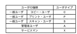
次に、画像形成装置1に接近したユーザを検知し、該ユーザに通知すべき状態が発生しているかどうかを判断して、ユーザに通知を行なう処理について、具体的に説明する。図3は、本実施形態における画像形成装置1のユーザの種類とユーザタイプの一覧表を示す。図3の一覧表は説明のためのものであって実際にこのテーブルを画像形成装置が保持する必要はない。ユーザの種類には、使用先において、コピーやプリントなど装置を通常に使用する「一般ユーザ」と、トナーや用紙などの消耗品を補充したり、装置の利用者を管理したりする「管理者ユーザ」と、装置の販売元などから派遣され、装置を定期的に保守・点検したり、必要に応じて部品を交換したりする「サービスマン」という3つに分類されている。さらに、「一般ユーザ」は、使用する機能に応じて、「コピー・ユーザ」「プリント・ユーザ」「スキャン・ユーザ」の3種類に分類されている。また、それぞれのユーザ種類を識別するために、図3に示すとおりに各々C/P/S/A/Xというユーザタイプを示すコードが割り振られている。ユーザが所持するRFID2には、予めユーザ識別情報として、これらのうち何れかのユーザタイプが記録されている。
<Example of message table configuration>
Next, a process for detecting a user who has approached the
図4は、画像形成装置1の各種状態とそれに対応するメッセージ、通知対象のユーザタイプの一覧を示したメッセージテーブルの例を示す。通知対象のユーザタイプ一覧では、0は対象外(通知しない)を示し、1は対象(通知する)を示している。例えば「用紙なし」の場合、対応するメッセージは「用紙を補給してください」であり、通知対象のユーザタイプは、C,P,A,Xとなる。スキャン機能のみを使用し、用紙を使用しないユーザ(ユーザタイプ=S)に対しては、通知対象外としているためである。
FIG. 4 shows an example of a message table showing a list of various states of the
また、例えば「ドラム交換要求」の場合、一般ユーザに通知しても交換が困難なため、管理者ユーザやサービスマンのみに通知するように通知対象のユーザタイプをA,Xとしている。状態の内容を示す状態情報そのものはメッセージテーブル401に含まれていなくともよい。その場合には、各メッセージ及び通知対象ユーザタイプは、配置順序により状態に対応付けられる。このようにメッセージテーブル401は、各種状態とそれに対応するメッセージ、通知対象のユーザタイプが予め決められた上で、ROM111に格納されている。
Further, for example, in the case of “drum exchange request”, since it is difficult to exchange even if a general user is notified, the user types to be notified are set to A and X so that only the administrator user or service person is notified. The state information itself indicating the content of the state may not be included in the message table 401. In that case, each message and the notification target user type are associated with the state by the arrangement order. As described above, the message table 401 is stored in the
<状態管理テーブルの構成例>
図5は、制御部10において、画像形成装置1の状態を管理するための状態管理テーブル501を示す。状態管理テーブル501は、画像形成装置1の各種状態と、それぞれの発生状況から構成されている。発生状況は、0がその状態が発生していないことを示し、1がその状態が発生中であることを示している。例えば、「用紙なし」と「ネットワークケーブル外れ」が発生している場合は、「用紙なし」「ネットワークケーブル外れ」の発生状況に1が記録されている。状態管理テーブル501についてもメッセージテーブル401と同様、状態情報そのものはテーブルに含まれなくともよい。
<Configuration example of status management table>
FIG. 5 shows a state management table 501 for managing the state of the
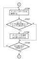
図6は、画像形成装置1で状態変化が発生したときの制御部10における処理の流れを示す。CPU109は、プリンタI/F部106やスキャナI/F部107などから状態変化の通知が来るのを待機し(ステップS601)、状態変化の通知を受け取ると、状態管理テーブルを参照し、該当する状態の発生状況に1(発生中)、または、0(解除)を書き込む(S602)。この例では、プリンタ部40における状態変化について説明するが、スキャナ部30についても同様である。
FIG. 6 shows a flow of processing in the
ステップS602は、より詳しくはたとえば次のようになる。プリンタ部40に含まれるプリンタ制御部806から状態変化が発生した旨の信号を受信した制御部10は、まず、プリンタ制御部806に対して、変化した状態の内容を示す情報を要求する。これに対してプリンタ制御部806はその内容を示す情報を返す。本例では、図5の状態管理テーブルの項目に対応した内容の情報が返される。たとえば、状態変化の内容が用紙残量に関して「用紙なし」状態に変化したのであれば、「用紙なし」を示す情報を返す。このとき複数の項目について状態変化が生じていれば、その全てを制御部10に返す。それを受信した制御部10は、図5の状態管理テーブルにおいて、受信した状態変化の内容に該当する項目に、該当する値をセットする。たとえば状態変化が「用紙あり」から「用紙なし」への変化であれば、「用紙なし」状態の項目に対応する生状況欄に1をセットする。また、逆に状態変換が「用紙なし」から「用紙あり」への変化であれば、「用紙なし」状態の項目に対応する生状況欄に0をセットする。このように、用紙やトナーなどの消耗品が切れた状態が生じたなら、その項目に該当する発生状況欄に1がセットされ、再度充填されたなら、該当する発生状況欄に0がセットされる。これはその他の障害についても同様であり、その発生と解消という双方向的な状態変化それぞれが生じる都度、状態管理テーブルは更新される。たとえば、スキャナ部においては、フィーダの原稿詰まりや光源となるライトバルブ切れ、原稿載置面に原稿が放置されたままフィーダが操作された状態など、ユーザによる解消が不可欠な状態変化は幾通りもあり得る。コピー動作においては、スキャナにおける状態変化とプリンタにおける状態変化とが複合的に生じ得る。
More specifically, step S602 is as follows. Upon receiving a signal indicating that a state change has occurred from the printer control unit 806 included in the
<状態変化通知処理>
図7,8は、画像形成装置1において、RFIDタグを検知してユーザを識別し、該ユーザに装置の状態変化の発生を通知するまでの処理の流れを示す。まず、RFIDリーダ11に接続するアンテナ12で、RFIDタグ2を所持したユーザの接近を検知すると(ステップS701)、RFIDリーダ11で、検知したRFIDタグ2に記録されている情報を読み取り、読み取った情報をRFIDリーダI/F102を介してCPU109に通知する(ステップS702)。なおRFIDタグ2の検知をトリガとしてステップS702から処理を開始しても良い。
<State change notification processing>
7 and 8 show the flow of processing in the
CPU109は、RFIDリーダ11から通知された情報が、ユーザ識別情報として認識可能かどうか、すなわち、ユーザタイプとしてC/P/S/A/Xの何れかの情報が含まれているかどうかを判別する(ステップS703)。ユーザ識別情報として認識できなかった場合は、再びステップS701に戻ってRFIDタグが検知されるのを待機する。ユーザ識別情報として認識できた場合、続いて状態管理テーブル501を参照し(ステップS704)、発生中の状態、すなわち発生状況に1がセットされている状態があるかどうかを検索する。(ステップS705)。状態管理テーブルに発生中の状態が一つも無かった場合には、再びステップS701に戻ってRFIDタグが検知されるのを待機する。
The
発生中の状態が見つかった場合、続いてメッセージテーブ401を参照し(ステップS706)、状態管理テーブル501で1となっていた状態に対応する「通知対象ユーザタイプ」に、ステップS703で認識したユーザタイプが該当するかどうかを判定する(ステップS707)。メッセージテーブ401と態管理テーブル501との対応付けは、たとえばその状態の並び順を同じにしておいても良いし、状態に対応する情報をインデックスとしてそれぞれに持っても良い。 If a state that is occurring is found, the message table 401 is subsequently referenced (step S706), and the user recognized in step S703 is set as the “notification target user type” corresponding to the state that is 1 in the state management table 501. It is determined whether the type is applicable (step S707). The correspondence between the message table 401 and the state management table 501 may be, for example, that the order of the states is the same, or may have information corresponding to the state as an index.
ステップS703で認識したユーザタイプが、該状態の通知対象のユーザに該当した場合は、該状態の対応するメッセージを音声出力部104に出力し、スピーカー14からメッセージを出力してユーザに通知する(ステップS708)。
If the user type recognized in step S703 corresponds to the user who is the notification target of the state, a message corresponding to the state is output to the
例えば、ステップS706において、状態管理テーブル501に登録された項目の内、「用紙なし」に対応する値が1であった場合、すなわち用紙切れが発生していた場合を考える。その場合、ステップS707では、図4のメッセージテーブル401において、「用紙なし」に対応する「通知対象ユーザタイプ」の欄のうち、ステップS703で認識したユーザタイプに対応する欄を参照する。4の例では、ユーザ対応がS以外で1となっている。したがってステップS703で認識したユーザタイプがS以外ならば、参照した欄の値は1となるはずであり、そのユーザはメッセージ通知対象となる。そしてこのユーザに対して「用紙を補給してください」という音声メッセージが出力される。 For example, consider a case where, in step S706, the value corresponding to “no paper” among the items registered in the state management table 501 is 1, that is, a paper out condition has occurred. In that case, in step S707, in the message table 401 of FIG. 4, the column corresponding to the user type recognized in step S703 is referred to in the “notification target user type” column corresponding to “no paper”. In the example of 4, the user correspondence is 1 except for S. Therefore, if the user type recognized in step S703 is other than S, the value of the referenced field should be 1, and the user is subject to message notification. Then, a voice message “please replenish paper” is output to this user.
一方、ステップS703で認識したユーザタイプが、状態の通知対象のユーザに該当しない場合には、他に発生中の状態がある場合には、該状態に対する処理を行なうために再びステップS706に移行する。他に発生中の状態が無い場合には、ステップS701に戻ってRFIDタグが検知されるのを待機する(ステップS709)。 On the other hand, if the user type recognized in step S703 does not correspond to the user to be notified of the state, and there is another state that is occurring, the process proceeds to step S706 again to perform processing for the state. . If there is no other occurrence state, the process returns to step S701 to wait for the RFID tag to be detected (step S709).
このように、ユーザのRFIDタグが検出された際には、状態管理テーブル501を参照して現在の状態を検索し、検索の結果得られ得た現在の状態を、検出されたRFIDタグに対応するユーザに通知するか、メッセージテーブル401を参照して判定する。そして、通知すると判定されれば、検索により得られた現在の状態に対応するメッセージをメッセージテーブル401から獲得し、そのメッセージを音声で出力する。もちろん音声以外のたとえばテキストやシンボルの表示でメッセージを出力しても良い。また、注意喚起のために音声を出力し、メッセージは表示出力するなど、複数のメディアを組み合わせて出力することもできる。 As described above, when the user's RFID tag is detected, the current state is searched with reference to the state management table 501, and the current state obtained as a result of the search corresponds to the detected RFID tag. To determine whether to notify the user who refers to the message table 401. If it is determined to be notified, a message corresponding to the current state obtained by the search is acquired from the message table 401, and the message is output by voice. Of course, you may output a message by display of a text or a symbol other than a voice. It is also possible to output a combination of multiple media, such as outputting a voice for alerting and displaying a message.
このために、装置に近づいたユーザのタイプ、装置に発生している状態に応じて、必要に応じた音声メッセージの通知が行なわれる。例えば、装置に近づいたユーザタイプがS(スキャンユーザ)であって、装置に発生している状態が「用紙なし」と「ネットワークケーブル外れ」であった場合、上記処理により、そのユーザに対しては「ネットワークケーブルを接続してください」という音声メッセージが通知される。 For this reason, a voice message is notified as necessary according to the type of the user approaching the apparatus and the state occurring in the apparatus. For example, when the user type approaching the device is S (scan user) and the statuses occurring in the device are “no paper” and “network cable disconnected”, the above processing is performed for the user. Will receive a voice message saying "Please connect the network cable".
[変形例]
なお、ユーザの携行するRFIDタグにはそのユーザに固有のIDを登録しておき、画像形成装置においてユーザIDとユーザタイプとを対応付ける表をRAM等に用意しておき、読み取ったユーザIDに対応するユーザタイプをそのテーブルから得るようにしてもよい。このように構成することで、ユーザタイプの変更を容易に行える。また、ユーザが利用できる画像形成装置が複数ある場合には、画像形成装置毎に相異なるユーザタイプを登録しておくこともできる。
[Modification]
In addition, an ID unique to the user is registered in the RFID tag carried by the user, and a table for associating the user ID and the user type is prepared in the RAM or the like in the image forming apparatus, and the read user ID is supported. The user type to be obtained may be obtained from the table. With this configuration, the user type can be easily changed. If there are a plurality of image forming apparatuses that can be used by the user, different user types can be registered for each image forming apparatus.
また、ユーザの識別をRFIDタグではなく、ユーザ自身の生体における特徴を認識しておこなうこともできる。このユーザ認識では、個人認証のような厳密さは必ずしも必要ではないので、指紋や網膜、静脈のパターンの認識のみならず、声などで識別することもできよう。ただし、指紋や網膜、静脈のパターンの認識は、ユーザ自身が画像形成装置に相当接近し、しかも該当部分をセンサに近傍におかねば認識困難である。そこで、ユーザが通常操作する部分、たとえばキーパッドの「スタート」キーに指紋センサを仕込んでおくなどして認識しやすさを向上させる必要がある。 Also, the user can be identified by recognizing the characteristics of the user's own living body instead of the RFID tag. This user recognition does not necessarily require strictness such as personal authentication, so it can be recognized not only by fingerprints, retina and vein patterns, but also by voice. However, it is difficult to recognize a fingerprint, retina, or vein pattern unless the user himself / herself is very close to the image forming apparatus and the corresponding part is close to the sensor. Therefore, it is necessary to improve the ease of recognition by installing a fingerprint sensor in a part that is normally operated by the user, for example, a “start” key of the keypad.
また、ユーザの識別をRFIDタグではなく、ユーザが操作部20のタッチパネル20aまたはキーパッド20bからユーザを識別するための識別情報を入力するようにしておこなうこともできる。この場合、画像形成装置1のROM110にユーザ識別情報を格納したテーブルを用意しておき、操作部20のタッチパネル20aまたはキーパッド20bから入力された情報と一致するユーザ識別情報がROM110に格納されている場合には、一致したユーザ識別情報に対応するユーザが画像形成装置1の近傍に存在することが認識できる。なお、画像形成装置1にてユーザ識別情報に一致する情報が入力されない場合は装置を使用不可とし、ユーザ識別情報に一致する情報が入力された場合は装置を使用可能とするよう、装置に使用制限をかけるようにしても良い。
Further, the user can be identified by inputting identification information for identifying the user from the
以上のように本実施形態によれば、状態の通知を、本来その状態を通知すべきユーザに対して行い、通知すべきでないユーザに対しては行わないように画像形成装置を構成できる。このために、消耗品の交換などのエラー状態の解除を、適当なユーザに対して促すことができる。さらに、ユーザを、ユーザの無線識別タグを読み取ることによって識別するため、ユーザが画像形成装置に接近することで、そのユーザを識別して、状態の発生を適切に通知できる。 As described above, according to the present embodiment, it is possible to configure the image forming apparatus so that the state notification is performed for the user who should originally notify the state and not for the user who should not be notified. For this reason, it is possible to prompt an appropriate user to cancel an error state such as replacement of consumables. Further, since the user is identified by reading the wireless identification tag of the user, the user can be identified by the user approaching the image forming apparatus and the occurrence of the state can be appropriately notified.
[第2の実施形態]
第1の実施形態では、装置に近づいたユーザを識別し、識別したユーザに応じて、単にメッセージを通知するか、あるいはしないかだけを切り替えていた。これにくわえて、識別したユーザに応じて、通知するメッセージ自体を切り替えるようにするとさらに利便性が高い。例えば、「トナーなし」状態が発生している場合には、一般ユーザに対しては、トナー補給を行なえる管理者に連絡するように通知し、管理者に対しては、トナーの保管場所を通知すれば、よりユーザに合った的確な通知とすることができる。そこで、第2の実施形態では、装置に近づいたユーザを識別し、識別したユーザと、装置で発生している状態に応じて、メッセージを切り替えて通知する例について説明する。
[Second Embodiment]
In the first embodiment, a user who has approached the apparatus is identified, and only whether a message is notified or not is switched according to the identified user. In addition to this, it is more convenient to switch the message itself to be notified according to the identified user. For example, when the “no toner” state has occurred, the general user is notified to contact the administrator who can supply toner, and the administrator is informed of the toner storage location. By notifying, it is possible to make the notification more appropriate for the user. Therefore, in the second embodiment, an example will be described in which a user who has approached the apparatus is identified, and the message is switched and notified according to the identified user and the state generated in the apparatus.
画像形成装置のハードウエア構成は、第1の実施形態と同様であるため、説明を割愛する。また、本実施形態では、メッセージの通知手段として操作パネルを使用し、文字による通知を行なうものとする。 Since the hardware configuration of the image forming apparatus is the same as that of the first embodiment, description thereof is omitted. Further, in the present embodiment, it is assumed that an operation panel is used as a message notification means, and notification is performed using characters.
図9は、本実施形態における画像形成装置1のユーザの種類とユーザタイプの一覧表を示す。第1の実施形態では、一般ユーザをさらに使用する機能毎に詳細に分類していたが、ここでは、ユーザの種類として「一般ユーザ」「管理者ユーザ」「サービスマン」の3種類に分類し、各々G,A,Xというユーザタイプが割り振られている。ユーザが所持するRFIDタグ2には、予めユーザ識別情報として、上記何れかのユーザタイプが記録されている。第1実施形態と同様、図9の一覧表は説明目的のもので、画像形成装置1が保持している必要はない。
FIG. 9 shows a list of user types and user types of the
図10は、本実施形態におけるメッセージテーブル1001の例を示す。図示するとおり、画像形成装置1の各状態とそれに対応するメッセージがユーザタイプ(G/A/X)ごとに格納されている。メッセージが「なし」の場合は、該ユーザタイプに対しては通知しないことを表している。なお、メッセージテーブル1001は、初期状態では、ROM111に格納されているが、後で使用先に応じてメッセージを変更できるように、電源投入時にRAMにロードし、操作パネル20や外部装置3から上書きできるようにしても良い。このメッセージテーブル1001は、第1実施形態のメッセージテーブル401に代えて本実施形態において用いられる。ただし、図10では「トナーなし」「ローラ交換要求」という2つの状態についてのみ示した。状態管理テーブル501に含まれている、通知対象の各状態について、ユーザタイプ毎に図10のようなメッセージがメッセージテーブル1001には登録される。
FIG. 10 shows an example of the message table 1001 in the present embodiment. As illustrated, each state of the
画像形成装置1でユーザに通知すべき状態変化が発生した場合、CPU109は、プリンタI/F部106やスキャナI/F部107などから状態変化を受け取り、状態管理テーブルの該当する状態の発生状況に1(発生中)、または、0(解除)を書き込む。この手順は第1の実施形態と同様である。また、状態管理テーブル501も第1実施形態と同様の構成である。
When a state change that should be notified to the user occurs in the
次に、画像形成装置1において、RFIDタグ2を検知してユーザを識別し、該ユーザに装置の状態変化の発生を通知するまでの処理について説明する。RFIDタグ2を検知してユーザを識別し、状態管理テーブル501に発生中の状態があるかどうかを検索するまでの処理は、図7のステップS701〜ステップS705と同様である。ステップS705で発生中の状態が見つかった場合、本実施形態では図11の手順が行われる。図11においては、ステップS705に続いてメッセージテーブル1001を参照し(ステップS1106)、見つかった状態、および、検知されたユーザタイプに該当するメッセージが存在するかどうかを判定する(ステップS1107)。前述の通り図10の例では図5の状態をすべてカバーしていないので対応付けは状態そのものを示す情報(たとえば「トナーなし」など)も各テーブルに登録しておき、それによって状態を対応付けることとなる。しかしメッセージテーブルが、図5に登録された全状態に対応して構成されていれば状態そのものを示す情報は不要であろう。
Next, a process until the
例えば、「ローラ交換要求」が発生していた場合、図10のメッセージテーブル1001の「Type」「メッセージ」を参照すると、認識されたユーザタイプがG(一般ユーザ)の場合はメッセージは存在しない。A(管理者ユーザ)、X(サービスマン)の場合はメッセージが存在する。メッセージが存在する場合、ユーザタイプに対応するメッセージをパネルI/F部101を介して操作パネルに出力し、操作パネル上にメッセージを文字列で表示してユーザに通知する(ステップS1108)。ステップS1107で、対応するメッセージが存在しない場合は、メッセージの出力は行なわれない。
For example, when a “roller replacement request” has occurred, referring to “Type” and “message” in the message table 1001 in FIG. 10, there is no message when the recognized user type is G (general user). A message exists in the case of A (administrator user) and X (service man). If there is a message, a message corresponding to the user type is output to the operation panel via the panel I /
複数の状態が同時に発生している場合は、次の発生中の状態に対する処理を行なうために再びステップS1106に移行し、他に発生中の状態が無い場合には、ステップS701に戻ってRFIDタグが検知されるのを待機する(ステップS1109)。 If a plurality of states occur simultaneously, the process proceeds to step S1106 again to perform processing for the next occurring state. If no other state is occurring, the process returns to step S701 to return to the RFID tag. Is detected (step S1109).
以上の処理により、装置に近づいたユーザのタイプ、装置に発生している状態に応じて、認識されたユーザに合った的確なメッセージの表示が行なわれる。例えば、装置に発生している状態が「トナーなし」であった場合、上記処理により、装置に近づいたユーザに応じて、「一般ユーザ」の場合は「トナーの残量がわずかです。管理者の佐藤さんに連絡してください。」、「管理者ユーザ」の場合は「トナーを補給してください。トナーは1F倉庫にあります。」、「サービスマン」の場合は「トナーのストックを確認してください。」というメッセージが表示される。 With the above processing, an accurate message suitable for the recognized user is displayed in accordance with the type of the user approaching the apparatus and the state generated in the apparatus. For example, when the status of the device is “no toner”, the above processing causes the user who has approached the device to “general user” and “the remaining amount of toner is very small. Please contact Mr. Sato. ”,“ Administrator User ”,“ Replenish toner. The toner is in the 1F warehouse. ” Please see "message appears.
[変形例]
第1実施形態、第2実施形態について共通であるが、メッセージテーブル401,1001を書き替え可能なROMやハードディスクに格納し、登録されたメッセージを、外部機器インターフェースを介して接続されたコンピュータ等や操作パネル20によって変更可能な構成とすることもできる。この場合には、たとえば図10の例であれば、サービスマンの個人名や消耗品の保存場所、管理者名等を、適宜装置の使用実態に合わせて変更することができる。
[Modification]
Although common to the first embodiment and the second embodiment, the message tables 401 and 1001 are stored in a rewritable ROM or hard disk, and the registered message is transferred to a computer connected via an external device interface, etc. The configuration can be changed by the
また、プリンタのエンジン部として、図12に示したような電子写真方式とは限らず、インクジェット方式や熱転写方式などについても同様に消耗品の補充や障害の発生をユーザに通知することができる。 In addition, the printer engine unit is not limited to the electrophotographic system as shown in FIG. 12, and the inkjet system and the thermal transfer system can also notify the user of the supply of consumables or the occurrence of a failure.
なお、本発明は、複数の機器(例えばホストコンピュータ、インタフェイス機器、リーダ、プリンタなど)から構成されるシステムに適用しても、一つの機器からなる装置(例えば、複写機、ファクシミリ装置など)に適用してもよい。また、本発明の目的は、前述した実施形態の機能を実現するソフトウェアのプログラムコードを記録した記憶媒体(または記録媒体)を、システムあるいは装置に供給し、そのシステムあるいは装置のコンピュータ(またはCPUやMPU)が記憶媒体に格納されたプログラムコードを読み出し実行することによっても達成される。この場合、記憶媒体から読み出されたプログラムコード自体が前述した実施形態の機能を実現することになり、そのプログラムコード自体およびプログラムコードを記憶した記憶媒体は本発明を構成することになる。 Note that the present invention can be applied to a system including a plurality of devices (for example, a host computer, an interface device, a reader, and a printer), and a device (for example, a copying machine and a facsimile device) including a single device. You may apply to. Another object of the present invention is to supply a storage medium (or recording medium) in which a program code of software that realizes the functions of the above-described embodiments is recorded to a system or apparatus, and the computer (or CPU or CPU) of the system or apparatus. (MPU) can also be achieved by reading and executing the program code stored in the storage medium. In this case, the program code itself read from the storage medium realizes the functions of the above-described embodiments, and the program code itself and the storage medium storing the program code constitute the present invention.
また、コンピュータが読み出したプログラムコードを実行することにより、前述した実施形態の機能が実現されるだけでなく、そのプログラムコードの指示に基づき、コンピュータ上で稼働しているオペレーティングシステム(OS)などが実際の処理の一部または全部を行い、その処理によって前述した実施形態の機能が実現される場合も含まれる。さらに、記憶媒体から読み出されたプログラムコードが、コンピュータに挿入された機能拡張カードやコンピュータに接続された機能拡張ユニットに備わるメモリに書込まれた後、そのプログラムコードの指示に基づき、その機能拡張カードや機能拡張ユニットに備わるCPUなどが実際の処理の一部または全部を行い、その処理によって前述した実施形態の機能が実現される場合も含まれる。 Further, by executing the program code read by the computer, not only the functions of the above-described embodiments are realized, but also an operating system (OS) running on the computer based on the instruction of the program code. A case where part or all of the actual processing is performed and the functions of the above-described embodiments are realized by the processing is also included. Furthermore, after the program code read from the storage medium is written into a memory provided in a function expansion card inserted into the computer or a function expansion unit connected to the computer, the function is determined based on the instruction of the program code. This includes a case where the CPU or the like provided in the expansion card or the function expansion unit performs part or all of the actual processing, and the functions of the above-described embodiments are realized by the processing.
1…画像形成装置、
2…RFIDタグ、
3…外部装置、
10…制御部、
11…RFIDリーダ、
12…アンテナ、
13…メッセージテーブル、
14…スピーカー、
20…操作パネル、
30…スキャナ部、
40…プリンタ部、
101…パネルI/F、
102…RFIDリーダI/F、
103…画像展開部、
104…音声出力部、
105…イメージメモリ、
106…プリンタI/F、
107…スキャナI/F、
108…外部機器I/F、
109…CPU、
110…RAM、
111…ROM
1 Image forming apparatus,
2 ... RFID tag,
3 ... External device,
10 ... control unit,
11 ... RFID reader
12 ... Antenna,
13 ... Message table
14 ... Speaker,
20 ... operation panel,
30: Scanner section,
40 ... Printer section
101 ... Panel I / F,
102 ... RFID reader I / F,
103. Image development unit,
104 ... audio output unit,
105: Image memory,
106: Printer I / F,
107 ... Scanner I / F,
108: External device I / F,
109 ... CPU,
110 ... RAM,
111 ... ROM
Claims (15)
前記ユーザが前記情報処理装置の近傍に存在する場合に、前記ユーザを識別するための識別情報を獲得する獲得手段と、
前記情報処理装置に発生し得る複数の装置状態を検知する検知手段と、
前記検知手段が検知する装置状態であって、前記獲得手段が獲得した前記ユーザの識別情報に対応する装置状態が発生しているか否かを判定する判定手段と、
前記判定手段が前記識別情報にかかるユーザに対応する装置状態が発生していると判定した場合、前記装置状態の発生を前記ユーザへ通知する通知手段
を備えることを特徴とする情報処理装置。 An information processing apparatus that can be operated by a plurality of users,
An acquisition means for acquiring identification information for identifying the user when the user exists in the vicinity of the information processing apparatus;
Detecting means for detecting a plurality of device states that may occur in the information processing device;
A determination unit that determines whether or not a device state corresponding to the identification information of the user acquired by the acquisition unit is the device state detected by the detection unit;
An information processing apparatus comprising: a notification unit configured to notify the user of the occurrence of the device state when the determination unit determines that a device state corresponding to the user related to the identification information has occurred.
前記通知手段は、前記判定手段が発生していると判定した装置状態に応じたメッセージを前記ユーザへ通知することを特徴とする請求項1に記載の情報処理装置。 Message storing means for storing a message corresponding to the device state;
The information processing apparatus according to claim 1, wherein the notification unit notifies the user of a message corresponding to an apparatus state determined to be generated by the determination unit.
前記通知手段は、前記判定手段が発生していると判定した装置状態に応じたメッセージであって、前記識別情報に応じたメッセージを前記ユーザに通知することを特徴とする請求項2に記載の情報処理装置。 The message storage means stores a message corresponding to the device status for each identification information,
The said notification means is a message according to the apparatus state which it determined with the said determination means having generate | occur | produced, Comprising: The message according to the said identification information is notified to the said user, The said user is characterized by the above-mentioned. Information processing device.
前記獲得手段は、前記識別情報入力手段に入力された入力指示に基づいて前記識別情報を獲得することを特徴とする請求項1乃至6のいずれか1項に記載の情報処理装置。 Having identification information input means for receiving an input instruction of the identification information from the user;
The information processing apparatus according to claim 1, wherein the acquisition unit acquires the identification information based on an input instruction input to the identification information input unit.
前記画像データ入力手段に入力された画像データに基づいて画像を形成するための複数の画像形成部を有する画像形成手段を有し、
前記装置状態は、前記複数の画像形成部材の状態であることを特徴とする請求項1乃至9のいずれか1項に記載の情報処理装置。 Image data input means for inputting image data;
An image forming unit having a plurality of image forming units for forming an image based on the image data input to the image data input unit;
The information processing apparatus according to claim 1, wherein the apparatus state is a state of the plurality of image forming members.
前記装置状態は、前記用紙収納部に収納される用紙の残量状態であることを特徴とする請求項10に記載の情報処理装置。 At least one of the plurality of image forming units is a paper storage unit that stores a paper on which the image is formed.
The information processing apparatus according to claim 10, wherein the apparatus state is a remaining amount state of sheets stored in the sheet storage unit.
前記装置状態は、前記現像剤収納部に収納される現像剤の残量状態であることを特徴とする請求項10に記載の情報処理装置。 At least one of the plurality of image forming units is a developer storage unit that stores a developer for forming an image on the paper;
The information processing apparatus according to claim 10, wherein the apparatus state is a remaining amount state of a developer stored in the developer storage unit.
前記装置状態は、前記搬送部が搬送する用紙の搬送状態であることを特徴とする請求項11に記載の情報処理装置。 At least one of the plurality of image forming units is a transport unit that transports the paper stored in the paper storage unit,
The information processing apparatus according to claim 11, wherein the apparatus state is a conveyance state of a sheet conveyed by the conveyance unit.
前記ユーザが前記情報処理装置の近傍に存在する場合に、前記ユーザを識別するための識別情報を獲得する獲得工程と、
前記情報処理装置に発生し得る複数の装置状態を検知する検知工程と、
前記検知工程にて検知した装置状態であって、前記獲得工程にて獲得した前記ユーザの識別情報に対応する装置状態が発生しているか否かを判定する判定工程と、
前記判定工程により前記識別情報にかかるユーザに対応する装置状態が発生していると判定された場合、前記装置状態の発生を前記ユーザへ通知するよう制御する制御工程と
を備えることを特徴とする情報処理装置の制御方法。 A method of controlling an information processing apparatus that can be operated by a plurality of users,
An acquisition step of acquiring identification information for identifying the user when the user exists in the vicinity of the information processing apparatus;
A detection step of detecting a plurality of device states that may occur in the information processing device;
A determination step of determining whether or not a device state corresponding to the identification information of the user acquired in the acquisition step is the device state detected in the detection step;
And a control step of controlling to notify the user of the occurrence of the device state when it is determined by the determination step that the device state corresponding to the user related to the identification information has occurred. A method for controlling an information processing apparatus.
Priority Applications (1)
| Application Number | Priority Date | Filing Date | Title |
|---|---|---|---|
| JP2005023942A JP2006205671A (en) | 2005-01-31 | 2005-01-31 | Information processor and its controlling method |
Applications Claiming Priority (1)
| Application Number | Priority Date | Filing Date | Title |
|---|---|---|---|
| JP2005023942A JP2006205671A (en) | 2005-01-31 | 2005-01-31 | Information processor and its controlling method |
Publications (1)
| Publication Number | Publication Date |
|---|---|
| JP2006205671A true JP2006205671A (en) | 2006-08-10 |
Family
ID=36963011
Family Applications (1)
| Application Number | Title | Priority Date | Filing Date |
|---|---|---|---|
| JP2005023942A Withdrawn JP2006205671A (en) | 2005-01-31 | 2005-01-31 | Information processor and its controlling method |
Country Status (1)
| Country | Link |
|---|---|
| JP (1) | JP2006205671A (en) |
Cited By (8)
| Publication number | Priority date | Publication date | Assignee | Title |
|---|---|---|---|---|
| JP2008058457A (en) * | 2006-08-30 | 2008-03-13 | Kyocera Mita Corp | Image forming apparatus |
| JP2013028083A (en) * | 2011-07-28 | 2013-02-07 | Kyocera Document Solutions Inc | Image forming device |
| JP2013220618A (en) * | 2012-04-18 | 2013-10-28 | Mitsubishi Electric Corp | Self-print terminal |
| JP2014138326A (en) * | 2013-01-17 | 2014-07-28 | Konica Minolta Inc | Image formation apparatus, image formation system, image formation method |
| JP2018061184A (en) * | 2016-10-07 | 2018-04-12 | シャープ株式会社 | Image forming apparatus, control program, and control method |
| JP2018114720A (en) * | 2017-01-20 | 2018-07-26 | ブラザー工業株式会社 | Ink-jet recording device |
| JP2019025702A (en) * | 2017-07-27 | 2019-02-21 | コニカミノルタ株式会社 | Image formation system, image formation apparatus and program |
| US10684804B2 (en) | 2018-05-25 | 2020-06-16 | Kyocera Document Solutions Inc. | Image forming apparatus and control method of image forming apparatus |
-
2005
- 2005-01-31 JP JP2005023942A patent/JP2006205671A/en not_active Withdrawn
Cited By (9)
| Publication number | Priority date | Publication date | Assignee | Title |
|---|---|---|---|---|
| JP2008058457A (en) * | 2006-08-30 | 2008-03-13 | Kyocera Mita Corp | Image forming apparatus |
| JP2013028083A (en) * | 2011-07-28 | 2013-02-07 | Kyocera Document Solutions Inc | Image forming device |
| JP2013220618A (en) * | 2012-04-18 | 2013-10-28 | Mitsubishi Electric Corp | Self-print terminal |
| JP2014138326A (en) * | 2013-01-17 | 2014-07-28 | Konica Minolta Inc | Image formation apparatus, image formation system, image formation method |
| US9188926B2 (en) | 2013-01-17 | 2015-11-17 | Konica Minolta, Inc. | Image forming apparatus, image forming system, and image forming method |
| JP2018061184A (en) * | 2016-10-07 | 2018-04-12 | シャープ株式会社 | Image forming apparatus, control program, and control method |
| JP2018114720A (en) * | 2017-01-20 | 2018-07-26 | ブラザー工業株式会社 | Ink-jet recording device |
| JP2019025702A (en) * | 2017-07-27 | 2019-02-21 | コニカミノルタ株式会社 | Image formation system, image formation apparatus and program |
| US10684804B2 (en) | 2018-05-25 | 2020-06-16 | Kyocera Document Solutions Inc. | Image forming apparatus and control method of image forming apparatus |
Similar Documents
| Publication | Publication Date | Title |
|---|---|---|
| US8040542B2 (en) | Display system, information distributing apparatus, electronic device, and portable terminal | |
| US5434650A (en) | System for transmitting a message including user request from image forming unit to management unit | |
| US8743381B2 (en) | Image forming apparatus and display method for a display portion of an image forming apparatus | |
| JP2006205671A (en) | Information processor and its controlling method | |
| JP2008269476A (en) | Information processor, information processing method and information processing system | |
| JP2006203808A (en) | Image processing device, information processor, information processing system, information processing method, program and storage medium | |
| JP2009135923A (en) | Image forming apparatus, image reading apparatus, and remote diagnostic method of image forming apparatus | |
| JP2013084135A (en) | Image forming system, image forming method, and printer driver | |
| JP2022084713A (en) | Information processing apparatus, control method of the same, and program | |
| JP2003099234A (en) | Electronic equipment and its service support system | |
| JP6489314B2 (en) | Image forming apparatus | |
| JP5866853B2 (en) | Image forming apparatus, management apparatus, image forming system, image forming apparatus control method, management apparatus control method, image forming apparatus control program, and management apparatus control program | |
| JP2007280223A (en) | Image forming apparatus and image processing method | |
| JP3890271B2 (en) | Image processing apparatus, image processing apparatus ordering method, program, and storage medium | |
| JP2015226294A (en) | Device with security function | |
| CN103581474A (en) | Data transmission device and image forming apparatus | |
| JP6171510B2 (en) | Image forming apparatus, operation guide method, program | |
| JP2005022342A (en) | Image processing system | |
| JP2007027970A (en) | Image forming apparatus | |
| JP2006347080A (en) | Image forming device, control method of image forming device, and control program of image forming device | |
| JP4282061B2 (en) | Image forming apparatus and copying apparatus | |
| US11330116B2 (en) | Image forming device and proposal processing prediction method for image forming device | |
| JP2013094980A (en) | Electronic apparatus and image forming apparatus | |
| US20230412739A1 (en) | Information processing apparatus and manual information processing system | |
| US10545445B2 (en) | Image forming apparatus that forms image on recording sheet, and image forming system |
Legal Events
| Date | Code | Title | Description |
|---|---|---|---|
| A300 | Withdrawal of application because of no request for examination |
Free format text: JAPANESE INTERMEDIATE CODE: A300 Effective date: 20080401 |