JP2006204676A - Game machine - Google Patents

Game machine Download PDF

Info

Publication number
JP2006204676A
JP2006204676A JP2005022789A JP2005022789A JP2006204676A JP 2006204676 A JP2006204676 A JP 2006204676A JP 2005022789 A JP2005022789 A JP 2005022789A JP 2005022789 A JP2005022789 A JP 2005022789A JP 2006204676 A JP2006204676 A JP 2006204676A
Authority
JP
Japan
Prior art keywords
frame
glass
front frame
closed
rail
Prior art date
Legal status (The legal status is an assumption and is not a legal conclusion. Google has not performed a legal analysis and makes no representation as to the accuracy of the status listed.)
Withdrawn
Application number
JP2005022789A
Other languages
Japanese (ja)
Other versions
JP2006204676A5 (en
Inventor
Takaaki Ichihara
高明 市原
Yoshihiro Sato
義浩 佐藤
Current Assignee (The listed assignees may be inaccurate. Google has not performed a legal analysis and makes no representation or warranty as to the accuracy of the list.)
Daiichi Shokai Co Ltd
Original Assignee
Daiichi Shokai Co Ltd
Priority date (The priority date is an assumption and is not a legal conclusion. Google has not performed a legal analysis and makes no representation as to the accuracy of the date listed.)
Filing date
Publication date
Application filed by Daiichi Shokai Co Ltd filed Critical Daiichi Shokai Co Ltd
Priority to JP2005022789A priority Critical patent/JP2006204676A/en
Publication of JP2006204676A publication Critical patent/JP2006204676A/en
Publication of JP2006204676A5 publication Critical patent/JP2006204676A5/ja
Withdrawn legal-status Critical Current

Links

Images

Landscapes

  • Pinball Game Machines (AREA)

Abstract

<P>PROBLEM TO BE SOLVED: To provide a game machine which can prevent the penetration of an illegal gadget into the playing area for a longer period of time without incurring the hourly aging of the components. <P>SOLUTION: A glass frame 52 is provided with a linear protrusion part 55 which is so arranged as to get on top of a guide rail 11 (inner rail 11b) with the front frame 5 closed. This can prevent the fraudulent attempt to open the open/close plates of the major prize winning device, to open the nails of the electric starter prize slots or others by penetrating the illegal gadget into the playing area 12. With such an arrangement, no extraneous force works on the linear protrusion part 55 of the glass frame 52 even with the font frame 5 closed and this will not incur the hourly aging of the linear protrusion part 55, thereby enabling the prevention of the penetration of the illegal gadget into the playing area 12 for a longer period of time. <P>COPYRIGHT: (C)2006,JPO&NCIPI

Description

本発明は、レール部材によって遊技領域が区画形成された遊技盤と、該遊技盤が取り付けられる本体枠と、前記遊技領域を視認可能に被覆する透明板が取り付けられる前面枠と、を備え、前記前面枠が前記本体枠に開閉自在に取り付けられる遊技機に関するものである。   The present invention comprises a gaming board in which a gaming area is defined by a rail member, a main body frame to which the gaming board is attached, and a front frame to which a transparent plate that covers the gaming area is visibly attached, The present invention relates to a gaming machine in which a front frame is attached to the main body frame so as to be freely opened and closed.

従来、一般に、レール部材によって遊技領域が区画形成された遊技盤を備えた遊技機の一例としてのパチンコ機は、遊技盤が取り付けられる本体枠と、遊技領域を視認可能に被覆する透明板が取り付けられる前面枠と、を備え、前面枠が本体枠に開閉自在に取り付けられて構成されている。また、このようなパチンコ機では、不正者がパチンコ機の下部(例えば、上皿や下皿等)に穴をあけてピアノ線等の不正道具をパチンコ機内に突っ込んで遊技領域に至らせ、その不正道具で大入賞口の開閉板を開けたり、始動口の釘を開ける等の不正行為が行われる場合がある。そして、このような不正行為を防止するために、特許文献1の構成や特許文献2の構成が提案されている。特許文献1の構成では、誘導レール(レール部材)の外周部分にレール飾りを設けると共に、窓枠(前面枠)を表枠(本体枠)に閉じた状態で窓枠及び透過窓(透明板)とレール飾りとの隙間を密閉する密閉部材を設け、遊技領域内への不正道具の侵入を防止するようになっている。特許文献2の構成では、ガラス扉(前面枠)と遊技盤との間にガラス破損防止板を配置して、該ガラス破損防止板の裏面に、ガラス扉を閉じた状態でガイドレール(レール部材)の下方部分における先端縁を嵌入する凹溝を設け、遊技領域内への不正道具の侵入を防止するようになっている。
特開2003−205151号公報(図5) 特開平11−33187号公報(図3)
Conventionally, in general, a pachinko machine as an example of a gaming machine including a gaming board in which a gaming area is partitioned by a rail member is attached with a main body frame to which the gaming board is attached and a transparent plate that covers the gaming area so as to be visible. And the front frame is attached to the main body frame so as to be openable and closable. In addition, in such a pachinko machine, an unauthorized person drills a hole in the lower part of the pachinko machine (for example, an upper plate, a lower plate, etc.) and thrusts an unauthorized tool such as a piano wire into the pachinko machine to reach the game area. There may be cases where fraudulent acts such as opening the open / close plate of the grand prize opening or opening the nail of the start opening with an unauthorized tool. And in order to prevent such a fraud, the structure of patent document 1 and the structure of patent document 2 are proposed. In the configuration of Patent Document 1, a rail decoration is provided on the outer periphery of the guide rail (rail member), and the window frame and the transmission window (transparent plate) with the window frame (front frame) closed to the front frame (main body frame). A sealing member that seals the gap between the rail decoration and the rail decoration is provided to prevent unauthorized tools from entering the game area. In the configuration of Patent Document 2, a glass breakage prevention plate is disposed between the glass door (front frame) and the game board, and the guide rail (rail member is closed on the back side of the glass breakage prevention plate with the glass door closed). ) Is provided with a recessed groove for fitting the leading edge thereof to prevent the unauthorized tool from entering the game area.
Japanese Patent Laying-Open No. 2003-205151 (FIG. 5) Japanese Patent Laid-Open No. 11-33187 (FIG. 3)

ところで、上記特許文献1及び特許文献2のいずれの構成においても、前面枠を閉じた状態で前面枠(あるいは透明板)の裏面と遊技盤側の密閉部材(ガラス破損防止板)との隙間を密閉して、遊技領域内への不正道具の侵入を防止するようになっている。しかしながら、このような構成では、前面枠を閉じた状態では常に前面枠(あるいは透明板)及び密閉部材(ガラス破損防止板)の相互間で押圧力が加わることになる。このため、密閉部材(ガラス破損防止板)自体が磨耗等によって変形したり、あるいは前面枠側のヒンジ機構にガタツキが生じる等の経時変化が起こり易くなる。そして、このような経時変化が起こった場合には、前面枠(あるいは透明板)の裏面と遊技盤側の密閉部材(ガラス破損防止板)との間に隙間が生じてしまい、遊技領域内への不正道具の侵入を防ぐことができなくなってしまう。本発明は、上記した事情に鑑みなされたもので、その目的とするところは、構成部材の経時変化を招来することなく、長期間に亘って遊技領域内への不正道具の侵入を防止することができる遊技機を提供することにある。   By the way, in any of the configurations of Patent Document 1 and Patent Document 2, the gap between the back surface of the front frame (or transparent plate) and the game board side sealing member (glass breakage prevention plate) is maintained with the front frame closed. It is sealed to prevent unauthorized tools from entering the game area. However, in such a configuration, a pressing force is always applied between the front frame (or transparent plate) and the sealing member (glass breakage prevention plate) when the front frame is closed. For this reason, the sealing member (glass breakage prevention plate) itself is likely to change over time, such as deformation due to wear or the like, or the hinge mechanism on the front frame side being rattled. And when such a change with time occurs, a gap is formed between the back surface of the front frame (or transparent plate) and the sealing member (glass breakage prevention plate) on the game board side, and it enters the game area. It will not be possible to prevent the intrusion of illegal tools. The present invention has been made in view of the above-described circumstances, and an object of the present invention is to prevent unauthorized tools from entering the game area over a long period of time without incurring changes in the components. It is to provide a gaming machine that can be used.

(解決手段1)
上記目標を達成するために、本発明の遊技機は、レール部材によって遊技領域が区画形成された遊技盤と、該遊技盤が取り付けられる本体枠と、前記遊技領域を視認可能に被覆する透明板が取り付けられる前面枠と、を備え、前記前面枠が前記本体枠に開閉自在に取り付けられる遊技機であって、前記前面枠に取り付けられて前記透明板を前記前面枠と前記本体枠との間に保持する透明板保持枠を備え、前記透明板保持枠には、後方に向けて延び出し前記前面枠を前記本体枠に対して閉じた状態で前記レール部材の外側又は内側に重ねて配置される突条部が設けられることを特徴とする。
なお、解決手段1に示す各手段として本実施形態における一例を以下に示す。レール部材は、内レール11bである。遊技領域は、遊技領域12である。遊技盤は、遊技盤4である。本体枠は、本体枠3である。透明板は、ガラス板51である。前面枠は、前面枠5である。遊技機は、パチンコ機1である。透明板保持枠は、ガラス枠52である。突条部は、突条部55である。
この場合、前面枠を閉じた状態で透明板保持枠の突条部がレール部材と重ねて配置される。このため、不正者が遊技機の下部(例えば、上皿や下皿等)に穴をあけてピアノ線等の不正道具を遊技機内に突っ込んで遊技領域に至らせようとしても、レール部材と重なる突条部がその侵入を阻止する。これにより、遊技領域内に不正道具を侵入させて大入賞口の開閉板を開けたり、始動口の釘を開ける等の不正行為を防止することができる。また、この構成によれば、前面枠を閉じた状態でも透明板保持枠の突条部に外力が加わることがないので、突条部の経時変化を招来することがなく、長期間に亘って遊技領域内への不正道具の侵入を防止することができる。
(Solution 1)
In order to achieve the above goal, the gaming machine of the present invention includes a gaming board in which a gaming area is defined by a rail member, a main body frame to which the gaming board is attached, and a transparent plate that covers the gaming area so as to be visible. A front frame to which the front frame is attached to the main body frame so as to be openable and closable, and the transparent plate is attached to the front frame between the front frame and the main body frame. The transparent plate holding frame is disposed to overlap the outside or the inside of the rail member in a state of extending toward the rear and closing the front frame with respect to the main body frame. A protruding portion is provided.
In addition, an example in this embodiment is shown below as each means shown in the solution means 1. The rail member is the inner rail 11b. The game area is a game area 12. The game board is a game board 4. The main body frame is the main body frame 3. The transparent plate is a glass plate 51. The front frame is the front frame 5. The gaming machine is a pachinko machine 1. The transparent plate holding frame is a glass frame 52. The protruding portion is the protruding portion 55.
In this case, the protruding portion of the transparent plate holding frame is disposed so as to overlap the rail member with the front frame closed. For this reason, even if an unauthorized person attempts to make a hole in the lower part of the gaming machine (for example, an upper plate or a lower plate) and push an unauthorized tool such as a piano wire into the gaming machine to reach the gaming area, it overlaps with the rail member. The ridges prevent the intrusion. Accordingly, it is possible to prevent an illegal act such as opening an open / close plate of the prize winning opening by opening an illegal tool into the game area and opening a nail of the starting opening. Further, according to this configuration, even when the front frame is closed, no external force is applied to the protrusions of the transparent plate holding frame, so that the protrusions do not change with time and can be used over a long period of time. It is possible to prevent unauthorized tools from entering the game area.

(解決手段2)
解決手段1において、前記透明板は、重なった複数枚の透明板から構成される。
この場合、透明板を複数枚配置することで、遊技領域内での遊技球の球流れによって生じる騒音に対する防音効果を高めることができる。
(Solution 2)
In the solution 1, the transparent plate is composed of a plurality of overlapping transparent plates.
In this case, by arranging a plurality of transparent plates, it is possible to enhance the soundproofing effect against noise generated by the ball flow of the game ball in the game area.

(解決手段3)
解決手段1又は解決手段2において、前記透明板及び前記透明板保持枠は、前記前面枠に着脱自在に装着される透明板ユニットを構成する。
なお、解決手段3に示す各手段として本実施形態における一例を以下に示す。透明板ユニットは、ガラスユニット50である。
この場合、前面枠に対する透明板の取り付け及び取り外し作業を容易にできる。とりわけ、複数枚の透明板から構成する場合には、透明板を1枚ずつ取り付けたりあるいは取り外すことなく、全ての透明板を一度に取り付けたりあるいは取り外すことができる。
(Solution 3)
In Solution 1 or Solution 2, the transparent plate and the transparent plate holding frame constitute a transparent plate unit that is detachably attached to the front frame.
In addition, an example in this embodiment is shown below as each means shown in the solution means 3. The transparent plate unit is a glass unit 50.
In this case, it is possible to easily attach and remove the transparent plate from the front frame. In particular, when a plurality of transparent plates are used, all the transparent plates can be attached or detached at once without attaching or removing the transparent plates one by one.

(解決手段4)
解決手段1乃至解決手段3において、前記突条部は、前記前面枠を閉じた状態で前記レール部材の外側の近傍位置に配置される。
この場合、重なった突条部とレール部材との間隔を狭くすることで、不正道具の侵入をより確実に阻止することができ、然も、突条部がレール部材の外側に配置されることで、突条部がレール部材による遊技球の誘導に悪影響を及ぼすことを回避することができる。
(Solution 4)
In Solution 1 to Solution 3, the protrusion is disposed in a position near the outside of the rail member with the front frame closed.
In this case, by narrowing the interval between the overlapping protrusions and the rail member, it is possible to more reliably prevent the intrusion of unauthorized tools, and the protrusions are disposed outside the rail member. Thus, it is possible to avoid the ridge portion from adversely affecting the guidance of the game ball by the rail member.

(解決手段5)
解決手段4において、前記遊技盤は、当該遊技盤の基板をなすベニヤ合板と、該ベニヤ合板の前面に一体的に設けられて前記遊技領域の外周部分を装飾する合成樹脂製のパネル飾りと、から構成されており、前記パネル飾りには、前記前面枠を閉じた状態で前記突条部が挿入される挿入溝が前記レール部材に沿った円弧状に穿設されている。
なお、解決手段4に示す各手段として本実施形態における一例を以下に示す。ベニヤ合板は、ベニヤ合板4aである。パネル飾りは、パネル飾り4bである。挿入溝は、挿入溝39である。
この場合、合成樹脂製のパネル飾りによってレール部材を一体成形した構成においても、レール部材に対して突条部を重ねて配置することができ、遊技領域内への不正道具の侵入を防止することができる。
(Solution 5)
In the solution 4, the game board includes a veneer plywood that forms a board of the game board, and a panel decoration made of synthetic resin that is integrally provided on the front surface of the veneer plywood and decorates an outer peripheral portion of the game area. In the panel decoration, an insertion groove into which the protruding portion is inserted in a state where the front frame is closed is formed in an arc shape along the rail member.
In addition, an example in this embodiment is shown below as each means shown in the solution means 4. The veneer plywood is a veneer plywood 4a. The panel decoration is a panel decoration 4b. The insertion groove is the insertion groove 39.
In this case, even in the configuration in which the rail member is integrally formed with the panel decoration made of synthetic resin, the protrusions can be arranged so as to overlap the rail member, and the intrusion of unauthorized tools into the game area can be prevented. Can do.

(解決手段6)
解決手段1乃至解決手段5において、前記突条部は、前記前面枠を閉じた状態で前記遊技領域の下部を囲むように配置される。
この場合、不正道具の下からの侵入を確実に阻止できる。なお、遊技領域内に不正道具を侵入させる不正行為は、主に不正者が座った状態で遊技機の下部に穴をあけて行う場合が多いため(長時間立った状態での不正行為は発見され易い)、不正道具の下からの侵入を阻止することで、標準的な不正行為に対する防犯効果を高めることができる。
(Solution 6)
In Solution 1 to Solution 5, the protruding portion is disposed so as to surround a lower portion of the game area with the front frame closed.
In this case, the intrusion from under the illegal tool can be surely prevented. Note that fraudulent acts that allow unauthorized tools to enter the gaming area are often performed by drilling holes in the lower part of gaming machines with an unauthorized person sitting (discovering illegal acts while standing for a long time) By preventing the intrusion from under the unauthorized tool, the crime prevention effect against standard fraud can be enhanced.

(解決手段7)
解決手段1乃至解決手段6において、前記突条部は、透明に形成される。
この場合、遊技者が透明板を透して前方から見ても突条部を目立たなくすることができ、美観を低下させることがない。
(Solution 7)
In the solution means 1 to the solution means 6, the said protrusion part is formed transparently.
In this case, even if the player sees from the front through the transparent plate, the protruding portion can be made inconspicuous, and the appearance is not deteriorated.

(解決手段8)
解決手段1乃至解決手段7において、前記突条部は、耐熱材料で形成される。
この場合、不正者が熱によって突条部に穴をあけようとしても耐熱性に優れた突条部に穴をあけることができないため、不正道具の侵入防止効果を高めることができる。
(Solution 8)
In Solution 1 to Solution 7, the protrusion is formed of a heat resistant material.
In this case, even if an unauthorized person tries to make a hole in the protruding portion by heat, it is impossible to make a hole in the protruding portion having excellent heat resistance.

本発明の構成によれば、前面枠を閉じた状態でも透明板保持枠の突条部に外力が加わることがないので、突条部の経時変化を招来することがなく、長期間に亘って遊技領域内への不正道具の侵入を防止することができる。   According to the configuration of the present invention, no external force is applied to the ridge portion of the transparent plate holding frame even when the front frame is closed. It is possible to prevent unauthorized tools from entering the game area.

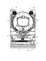
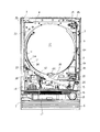
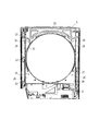
以下、図面を参照して本発明の好適な実施形態について説明する。先ず、図1乃至図4を参照して実施形態に係るパチンコ機の全体構成について説明する。図1は、パチンコ機を示す正面図である。図2は、本体枠及び前面枠を開放した状態のパチンコ機を示す斜視図である。図3は、前面枠を示す裏面図である。図4は、前面枠を取り外した状態のパチンコ機を示す正面図である。   Hereinafter, preferred embodiments of the present invention will be described with reference to the drawings. First, the overall configuration of the pachinko machine according to the embodiment will be described with reference to FIGS. 1 to 4. FIG. 1 is a front view showing a pachinko machine. FIG. 2 is a perspective view showing the pachinko machine with the main body frame and the front frame opened. FIG. 3 is a rear view showing the front frame. FIG. 4 is a front view showing the pachinko machine with the front frame removed.

図1及び図2に示すように、パチンコ機1は、外枠2、本体枠3、遊技盤4、前面枠5等を備えて構成されている。外枠2は、上下左右の枠材によって縦長四角形の枠状に形成され、外枠2の前側下部には、本体枠3の下面を受ける下受板6を有している。外枠2の前面一側には、ヒンジ機構7によって本体枠3が前方に開閉可能に装着されている。本体枠3は、前枠体8、遊技盤装着部9、及び機構部10を合成樹脂材によって一体成形することで構成されている。本体枠3の前側に形成された前枠体8は、外枠2前側の下受板6を除く外郭形状に対応する大きさの矩形枠状に形成されている。   As shown in FIGS. 1 and 2, the pachinko machine 1 includes an outer frame 2, a main body frame 3, a game board 4, a front frame 5, and the like. The outer frame 2 is formed in a vertically rectangular frame shape by upper, lower, left and right frame members, and has a lower plate 6 that receives the lower surface of the main body frame 3 at the lower front side of the outer frame 2. A main body frame 3 is attached to the front side of the outer frame 2 by a hinge mechanism 7 so as to be opened and closed forward. The main body frame 3 is configured by integrally molding the front frame body 8, the game board mounting portion 9, and the mechanism portion 10 with a synthetic resin material. The front frame 8 formed on the front side of the main body frame 3 is formed in a rectangular frame shape having a size corresponding to the outer shape excluding the support plate 6 on the front side of the outer frame 2.

また、本体枠3は、合成樹脂材によって一体に形成されると共に、前面側に遊技盤装着部9が背面側に機構部10がそれぞれ形成されている。これによって、合成樹脂製の本体枠3は、従来の前枠(内枠、前面枠等と呼ばれることがある)と、機構板(裏機構板、裏セット板等と呼ばれることがある)との機能を兼ね備えている。   The main body frame 3 is integrally formed of a synthetic resin material, and a game board mounting portion 9 is formed on the front side, and a mechanism portion 10 is formed on the back side. As a result, the synthetic resin main body frame 3 has a conventional front frame (sometimes called an inner frame, a front frame, etc.) and a mechanism plate (sometimes called a back mechanism plate, a back set plate, etc.). It has a function.

前枠体8の後部に一体的に形成された遊技盤装着部9には、遊技盤4が前方から着脱交換可能に装着されるようになっている。また、遊技盤装着部9の左側部には、図3に示すように、係合突部33が上下に2つ形成され、遊技盤装着部9の右側部には、係合凹部45が上下に2つ形成されている。遊技盤4の盤面(前面)の左側部には係合突部33と対応する係止穴34が上下に2つ形成され、遊技盤4の盤面の右側部には係合凹部45と対応する係合フック35が上下に2つ形成されている。係合フック35は、遊技盤4と遊技盤装着部9とを係脱可能に係止する。   A game board 4 is attached to the game board mounting part 9 formed integrally with the rear part of the front frame 8 so as to be detachable and replaceable from the front. Further, as shown in FIG. 3, two engaging protrusions 33 are formed on the left side of the game board mounting part 9 and the engagement concave part 45 is provided on the right side of the game board mounting part 9 in the vertical direction. Two are formed. Two locking holes 34 corresponding to the engagement protrusions 33 are formed on the left side of the board surface (front surface) of the game board 4 and the engagement recesses 45 are provided on the right side of the board surface of the game board 4. Two engaging hooks 35 are formed on the upper and lower sides. The engagement hook 35 detachably engages the game board 4 and the game board mounting part 9 with each other.

遊技盤4の盤面には、外レール11aと内レール11bとを備えた案内レール11が設けられており、該案内レール11(内レール11b)の内側に遊技領域12が区画形成されている。遊技領域12内には、遊技に関する役物装置、例えば、センター役物と呼ばれる役物装置40、図柄表示装置(例えば、液晶表示器、EL表示器、プラズマ表示器、CRT等)41、電動始動入賞口42、大入賞口装置43、アウト口44、等の各種構成部材が配置されている。また、遊技盤4の右下部分となる内レール11bの外周には、前面枠5が閉じられた状態において、後述するガラスユニット50の突条部55が挿入される挿入溝39が内レール11bに沿った円弧状に穿設されている。即ち、本実施形態の遊技盤4は、当該遊技盤4の基板をなすベニヤ合板4aと、該ベニヤ合板4aの前面に一体的に設けられて遊技領域12の外周部分を装飾する合成樹脂製のパネル飾り4bと、から構成されており、パネル飾り4bには、合成樹脂製の案内レール11が一体成形されている。このため、遊技盤4を構成するパネル飾り4bの右下部分には、前面枠5を閉じた状態でパネル飾り4bが突条部55と干渉しないように挿入溝39が穿設されている。   A guide rail 11 having an outer rail 11a and an inner rail 11b is provided on the board surface of the game board 4, and a game area 12 is defined inside the guide rail 11 (inner rail 11b). In the game area 12, a game-related device such as a center device 40, a symbol display device (for example, a liquid crystal display, EL display, plasma display, CRT, etc.) 41, electric start Various components such as a winning opening 42, a large winning opening device 43, and an out opening 44 are arranged. Further, on the outer periphery of the inner rail 11b, which is the lower right portion of the game board 4, there is an insertion groove 39 into which a protrusion 55 of a glass unit 50 described later is inserted when the front frame 5 is closed. Is drilled in a circular arc shape along. That is, the game board 4 of the present embodiment is made of a synthetic resin that is integrally provided on the front surface of the veneer plywood 4a that forms the board of the game board 4 and decorates the outer peripheral portion of the game area 12. The panel decoration 4b is composed of a guide rail 11 made of synthetic resin. For this reason, an insertion groove 39 is formed in the lower right portion of the panel decoration 4b constituting the game board 4 so that the panel decoration 4b does not interfere with the protrusion 55 in a state where the front frame 5 is closed.

遊技盤装着部9よりも下方に位置する前枠体8の前側下部の一側寄りには、下部スピーカ14が装着されている。また、前枠体8前面の下部領域内の上側部分には、遊技盤4の発射通路に向けて遊技球を導く発射レール15が傾斜状に装着されている。一方、前枠体8前面の下部領域内の下側部分には、下前面部材16が装着されている。下前面部材16前面のほぼ中央には、下皿17が設けられ、片側寄りには操作ハンドル18が設けられている。   A lower speaker 14 is attached to one side of the front lower portion of the front frame body 8 located below the game board mounting portion 9. A launch rail 15 that guides a game ball toward the launch path of the game board 4 is attached to the upper portion in the lower region of the front surface of the front frame 8 in an inclined manner. On the other hand, a lower front member 16 is attached to a lower portion in the lower area of the front surface of the front frame body 8. A lower pan 17 is provided substantially at the center of the front surface of the lower front member 16, and an operation handle 18 is provided closer to one side.

本体枠3(前枠体8)のヒンジ機構7が設けられる側とは反対側となる開放側の後面には、外枠2に対して本体枠3を施錠する機能と、本体枠3に対して前面枠5を施錠する機能とを兼ね備えた施錠装置19が装着されている。施錠装置19は、外枠2に設けられた閉止具20に係脱可能に係合して本体枠3を閉鎖状態に施錠する上下複数の本体枠施錠フック21と、前面枠5の開放側の後面に設けられた閉止具22に係脱可能に係合して前面枠5を閉鎖状態に施錠する上下複数の扉施錠フック23とを備えている。   A function of locking the main body frame 3 with respect to the outer frame 2 is provided on the rear surface of the main body frame 3 (front frame body 8) opposite to the side where the hinge mechanism 7 is provided. A locking device 19 having a function of locking the front frame 5 is attached. The locking device 19 includes a plurality of upper and lower body frame locking hooks 21 that are detachably engaged with a closing tool 20 provided on the outer frame 2 to lock the main body frame 3 in a closed state, and an open side of the front frame 5. There are provided a plurality of upper and lower door locking hooks 23 that are detachably engaged with a closing tool 22 provided on the rear surface and lock the front frame 5 in a closed state.

しかして、シリンダー錠24の鍵穴に鍵が挿入されて一方向に回動操作されることで、本体枠施錠フック21と外枠2の閉止具20との係合が解除されて本体枠3が解錠され、これとは逆方向に鍵が回動操作されることで、扉施錠フック23と前面枠5の閉止具22との係合が解除されて前面枠5が解錠されるようになっている。なお、シリンダー錠24の前端部は、パチンコ機1の前方から鍵を挿入して解錠操作が行えるように、前枠体8及び下前面部材16を貫通して下前面部材16の前面に露出して配置されている。   Thus, when the key is inserted into the key hole of the cylinder lock 24 and rotated in one direction, the engagement between the main body frame locking hook 21 and the closing tool 20 of the outer frame 2 is released, and the main body frame 3 is moved. When unlocked and the key is rotated in the opposite direction, the engagement between the door locking hook 23 and the closing tool 22 of the front frame 5 is released, and the front frame 5 is unlocked. It has become. The front end of the cylinder lock 24 is exposed to the front surface of the lower front member 16 through the front frame body 8 and the lower front member 16 so that the unlocking operation can be performed by inserting a key from the front of the pachinko machine 1. Are arranged.

本体枠3前面の一側には、ヒンジ機構25によって前面枠5が前方に開閉可能に装着されている。前面枠5は、前枠体8の上端から下前面部材16の上縁に亘る部分を覆う大きさに形成され、そのほぼ中央部には、遊技盤4の遊技領域12を前方から透視可能なほぼ円形状の開口窓30が形成されている。前面枠5の前側には、開口窓30の周囲において、左右両側部に枠ランプ27が、下部に上皿28が、上部に上部スピーカ29が装着されている。一方、前面枠5の後側には、図4に示すように、開口窓30の周囲において、プレス加工された複数の金属製フレーム部材によって構成される扉本体フレーム26が取り付けられ、該扉本体フレーム26を介してガラスユニット50が取り付けられている。なお、扉本体フレーム26の後面には、開口窓30外周の右上、右下、左上、左下となる4箇所にガラスユニット50取り付け用のスタッドボルト36が設けられている。   A front frame 5 is attached to one side of the front surface of the main body frame 3 by a hinge mechanism 25 so as to be opened and closed forward. The front frame 5 is formed to have a size that covers a portion extending from the upper end of the front frame 8 to the upper edge of the lower front member 16, and the game area 12 of the game board 4 can be seen through from the front at substantially the center thereof. A substantially circular opening window 30 is formed. On the front side of the front frame 5, around the opening window 30, frame lamps 27 are mounted on both left and right sides, an upper plate 28 is mounted on the lower side, and an upper speaker 29 is mounted on the upper side. On the other hand, as shown in FIG. 4, a door body frame 26 composed of a plurality of pressed metal frame members is attached to the rear side of the front frame 5 around the opening window 30. A glass unit 50 is attached via the frame 26. On the rear surface of the door main body frame 26, stud bolts 36 for attaching the glass unit 50 are provided at four locations on the outer periphery of the opening window 30, which are the upper right, lower right, upper left, and lower left.

前面枠5の後側における開口窓30下方のヒンジ寄り部分には、遊技球を上皿28に導く上皿用球案内筒31が突設されている。そして、前面枠5が閉じられた状態において、上皿用球案内筒31の後端部が球払出装置の球払出口32と連通して配置されることで、球払出装置から払い出された遊技球が上皿用球案内筒31を通って前面枠5前側の上皿28に払い出されるようになっている。また、前面枠5の後側における開放側には、本体枠3の扉施錠フック23と係脱可能な前述の閉止具22が設けられている。一方、前面枠5の後側におけるヒンジ側には、その上下方向の中間高さ位置近傍から下部近傍に亘る長さを有する金属板からなる扉拘束体37が設けられている。扉拘束体37は、前面枠5が閉じられた状態において、本体枠3に設けられた扉用拘束部38(図3参照)との係合によって前面枠5が前方に向けて不測にこじ開けられて不正行為がなされることを防止するようになっている。   On the rear side of the front frame 5, a portion near the hinge below the opening window 30 is provided with an upper plate ball guide tube 31 that guides the game ball to the upper plate 28. And in the state which the front frame 5 was closed, it was paid out from the ball paying device by arranging the rear end part of the ball guide tube 31 for the upper dish in communication with the ball paying outlet 32 of the ball paying device. The game ball passes through the upper plate ball guide tube 31 and is paid out to the upper plate 28 on the front side of the front frame 5. Further, on the open side of the rear side of the front frame 5, the above-described closing tool 22 that can be engaged with and detached from the door locking hook 23 of the main body frame 3 is provided. On the other hand, on the hinge side on the rear side of the front frame 5, a door restraint body 37 made of a metal plate having a length from the vicinity of the intermediate height position in the vertical direction to the vicinity of the lower portion is provided. When the front frame 5 is closed, the door restraint body 37 is unexpectedly pryed open toward the front by engagement with the door restraint portion 38 (see FIG. 3) provided on the main body frame 3. To prevent fraud.

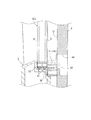
次に、本実施形態の要部を構成するガラスユニット50について図5及び図6を参照して説明する。図5(A)は、ガラスユニットを示す正面図である。図5(B)は、ガラスユニットを示す縦断面図である。図6は、ガラスユニットの突条部が遊技盤の挿入溝に挿入した状態を示す部分拡大縦断面図である。   Next, the glass unit 50 which comprises the principal part of this embodiment is demonstrated with reference to FIG.5 and FIG.6. FIG. 5A is a front view showing the glass unit. FIG. 5B is a longitudinal sectional view showing the glass unit. FIG. 6 is a partially enlarged longitudinal sectional view showing a state in which the protrusions of the glass unit are inserted into the insertion grooves of the game board.

図5(A)(B)に示すように、ガラスユニット50は、ほぼ円形状の2枚のガラス板51と、該ガラス板51の外形形状に沿った額縁状(環状)に形成されて2枚のガラス板51を前後方向に重ねて保持するガラス枠52と、を備えている。ガラス枠52は、耐熱性に優れた合成樹脂材料(例えば、各種熱硬化性樹脂等)によって形成されており、2枚のガラス板51の外周縁がそれぞれガラス枠52の枠内に接着剤で接着されることで、ガラスユニット50が構成されている。   As shown in FIGS. 5 (A) and 5 (B), the glass unit 50 is formed of two substantially circular glass plates 51 and a frame shape (annular) 2 along the outer shape of the glass plate 51. And a glass frame 52 that holds the glass plates 51 stacked in the front-rear direction. The glass frame 52 is formed of a synthetic resin material having excellent heat resistance (for example, various thermosetting resins), and the outer peripheral edges of the two glass plates 51 are respectively bonded to the frame of the glass frame 52 with an adhesive. The glass unit 50 is configured by bonding.

ガラス枠52の外周であってその右上、右下、左上、左下の4箇所には、前面枠5の扉本体フレーム26に設けられた4つのスタッドボルト36と個々に対応して取付片53が形成されている。取付片53には、スタッドボルト36を挿通するための挿通穴54が穿設されている。また、ガラス枠52後側における下側の円弧部分には、該円弧形状(ガラス枠52の枠形状)に沿って突条部55が突出形成されている。なお、取付片53及び突条部55は、それぞれ耐熱性に優れた合成樹脂材料からなるガラス枠52と一体成形されるものであり、ガラス枠52と同様に耐熱性に優れている。   There are four stud bolts 36 provided on the door body frame 26 of the front frame 5 and attachment pieces 53 respectively corresponding to the outer periphery of the glass frame 52 at the upper right, lower right, upper left, and lower left. Is formed. The attachment piece 53 is provided with an insertion hole 54 for inserting the stud bolt 36. Further, on the lower arc portion on the rear side of the glass frame 52, a protrusion 55 is formed so as to protrude along the arc shape (the frame shape of the glass frame 52). The attachment piece 53 and the protruding portion 55 are each integrally formed with a glass frame 52 made of a synthetic resin material having excellent heat resistance, and are excellent in heat resistance like the glass frame 52.

しかして、ガラスユニット50は、ガラス枠52を前面枠5の開口窓30に後側から嵌入させると共に、取付片53の挿通穴54内にスタッドボルト36を挿通し、この状態からスタッドボルト36にナット(図示しない)を締め付けることで、前面枠5と一体的に取り付けられる。これにより、前面枠5の開口窓30は、ガラスユニット50のガラス板51によって被覆された状態となる。   Thus, the glass unit 50 inserts the glass frame 52 into the opening window 30 of the front frame 5 from the rear side, and inserts the stud bolt 36 into the insertion hole 54 of the mounting piece 53, and from this state to the stud bolt 36. By tightening a nut (not shown), the front frame 5 is attached integrally. As a result, the opening window 30 of the front frame 5 is covered with the glass plate 51 of the glass unit 50.

ところで、上記したようにガラスユニット50が取り付けられた前面枠5を閉じた状態では、図6に示すように、ガラス枠52後側の下側円弧部分に設けられた突条部55が案内レール11(内レール11b)の外周部分を覆うようにして配置される。言い換えれば、突条部55が遊技領域12の下部を区画形成する案内レール11(内レール11b)を囲むようにして配置される。具体的に、突条部55の部位において、遊技盤4の中心線(アウト口44)より左側に配置される部位は、外レール11aと内レール11bの間に配置された状態で案内レール11(内レール11b)を囲み、遊技盤4の中心線(アウト口44)より右側に配置される部位は、遊技盤4の右下部分に穿設された挿入溝39内に挿入された状態(図6に示す状態)で案内レール11(内レール11b)を囲む。これにより、不正者がパチンコ機1の下部(例えば、上皿28や下皿17等)に穴をあけてピアノ線等の不正道具をパチンコ機1内に突っ込んで遊技領域12に至らせようとしても、案内レール11(内レール11b)と重なった突条部55がその侵入を阻止する。なお、前面枠5の開口窓30は、その開口端部が全周に亘って案内レール11に一致するよう形成されており、これによって、案内レール11の外側に位置する突条部55は、案内レール11に隠れて遊技者から概ね見えないようになっている。   By the way, in the state where the front frame 5 to which the glass unit 50 is attached as described above is closed, as shown in FIG. 6, the protrusion 55 provided on the lower arc portion on the rear side of the glass frame 52 is a guide rail. 11 (inner rail 11b) is arranged so as to cover the outer peripheral portion. In other words, the protrusion 55 is disposed so as to surround the guide rail 11 (inner rail 11b) that defines and forms the lower portion of the game area 12. Specifically, in the portion of the ridge portion 55, the portion disposed on the left side of the center line (out port 44) of the game board 4 is disposed between the outer rail 11a and the inner rail 11b, and the guide rail 11 is disposed. A portion that surrounds the (inner rail 11b) and is disposed on the right side of the center line (out port 44) of the game board 4 is inserted into an insertion groove 39 formed in the lower right portion of the game board 4 ( The guide rail 11 (inner rail 11b) is enclosed in the state shown in FIG. As a result, an unauthorized person attempts to make a hole in the lower part of the pachinko machine 1 (for example, the upper plate 28, the lower plate 17 or the like) and to push an unauthorized tool such as a piano wire into the pachinko machine 1 to reach the game area 12. In addition, the protrusion 55 that overlaps the guide rail 11 (inner rail 11b) prevents the intrusion. In addition, the opening window 30 of the front frame 5 is formed so that the opening end portion thereof coincides with the guide rail 11 over the entire circumference, and thereby, the protrusion 55 positioned outside the guide rail 11 is It is hidden from the guide rail 11 so as not to be seen from the player.

以上のように、本実施形態の構成によれば、前面枠5を閉じた状態でガラス枠52の突条部55が案内レール11(内レール11b)と重ねて配置される。このため、不正者がパチンコ機1の下部(例えば、上皿28や下皿17等)に穴をあけてピアノ線等の不正道具をパチンコ機1内に突っ込んで遊技領域12に至らせようとしても、案内レール11と重なった突条部55がその侵入を阻止する。これにより、遊技領域12内に不正道具を侵入させて大入賞口装置43の開閉板を開けたり、電動始動入賞口42の釘を開ける等の不正行為を防止することができる。また、この構成によれば、前面枠5を閉じた状態でもガラス枠52の突条部55に外力が加わることがないので、突条部55の経時変化を招来することがなく、長期間に亘って遊技領域12内への不正道具の侵入を防止することができる。   As described above, according to the configuration of the present embodiment, the protruding portion 55 of the glass frame 52 is disposed so as to overlap the guide rail 11 (inner rail 11b) with the front frame 5 closed. For this reason, an unauthorized person attempts to make a hole in the lower part of the pachinko machine 1 (for example, the upper plate 28, the lower plate 17 or the like) and to push an unauthorized tool such as a piano wire into the pachinko machine 1 to reach the game area 12. However, the protrusion 55 that overlaps the guide rail 11 prevents the intrusion. Accordingly, it is possible to prevent an illegal act such as intrusion of an unauthorized tool into the game area 12 to open the open / close plate of the big prize opening device 43 or the opening of the nail of the electric start winning opening 42. Further, according to this configuration, since no external force is applied to the ridges 55 of the glass frame 52 even when the front frame 5 is closed, the ridges 55 do not change with time and can be used for a long time. It is possible to prevent unauthorized tools from entering the game area 12.

また、本実施形態の構成によれば、ガラス板51は、重なった複数枚のガラス板51から構成される。これにより、複数枚のガラス板51を重ねて配置することで、遊技領域12内での遊技球の球流れによって生じる騒音に対する防音効果を高めることができる。   Moreover, according to the structure of this embodiment, the glass plate 51 is comprised from the several glass plate 51 which overlapped. Thereby, the soundproof effect with respect to the noise which arises by the ball flow of the game ball in the game area | region 12 can be heightened by arrange | positioning the several glass plate 51 in piles.

また、ガラス板51及びガラス枠52は、前面枠5に着脱自在に装着されるガラスユニット50を構成する。これにより、前面枠5に対するガラス板51の取り付け及び取り外し作業を容易にできる。とりわけ、本実施形態のように、複数枚のガラス板51から構成する場合には、ガラス板51を1枚ずつ取り付けたりあるいは取り外すことなく、全てのガラス板51を一度に取り付けたりあるいは取り外すことができる。   Further, the glass plate 51 and the glass frame 52 constitute a glass unit 50 that is detachably attached to the front frame 5. Thereby, the attachment and removal operation | work of the glass plate 51 with respect to the front frame 5 can be made easy. In particular, as in the present embodiment, when a plurality of glass plates 51 are used, all the glass plates 51 can be attached or removed at once without attaching or removing the glass plates 51 one by one. it can.

また、突条部55は、前面枠5を閉じた状態で案内レール11の外側の近傍位置に配置される。これにより、重なった突条部55と案内レール11との間隔を狭くすることで、不正道具の侵入をより確実に阻止することができ、然も、突条部55が案内レール11の外側に配置されることで、突条部55が案内レール11による遊技球の誘導に悪影響を及ぼすことを回避することができる。   Further, the protruding portion 55 is disposed at a position near the outside of the guide rail 11 with the front frame 5 closed. Thereby, by narrowing the interval between the overlapping ridges 55 and the guide rails 11, it is possible to more reliably prevent intrusion of unauthorized tools, and the ridges 55 are located outside the guide rails 11. By being arranged, it is possible to avoid the ridge portion 55 from adversely affecting the guidance of the game ball by the guide rail 11.

また、遊技盤4は、当該遊技盤4の基板をなすベニヤ合板4aと、該ベニヤ合板4aの前面に一体的に設けられて遊技領域12の外周部分を装飾する合成樹脂製のパネル飾り4bと、から構成されており、パネル飾り4bには、前面枠5を閉じた状態で突条部55が挿入される挿入溝39が案内レール11に沿った円弧状に穿設されている。これにより、本実施形態のように、合成樹脂製のパネル飾り4bによって案内レール11を一体成形した構成においても、案内レール11に対して突条部55を重ねて配置することができ、遊技領域12内への不正道具の侵入を防止することができる。   The game board 4 includes a veneer plywood 4a that forms a board of the game board 4, and a panel decoration 4b made of synthetic resin that is integrally provided on the front surface of the veneer plywood 4a and decorates the outer peripheral portion of the game area 12. In the panel decoration 4b, an insertion groove 39 into which the protrusion 55 is inserted with the front frame 5 closed is formed in an arc shape along the guide rail 11. Thereby, even in the configuration in which the guide rail 11 is integrally formed with the synthetic resin panel ornament 4b as in the present embodiment, the protrusion 55 can be disposed so as to overlap the guide rail 11, and the game area It is possible to prevent unauthorized tools from entering the inside 12.

また、突条部55は、前面枠5を閉じた状態で遊技領域12の下部を囲むように配置される。これにより、不正道具の下からの侵入を確実に阻止できる。なお、遊技領域12内に不正道具を侵入させる不正行為は、主に不正者が座った状態でパチンコ機1の下部に穴をあけて行う場合が多いため(長時間立った状態での不正行為は発見され易い)、不正道具の下からの侵入を阻止することで、標準的な不正行為に対する防犯効果を高めることができる。   Further, the protrusion 55 is arranged so as to surround the lower portion of the game area 12 with the front frame 5 closed. Thereby, the intrusion from under the illegal tool can be surely prevented. It is to be noted that fraudulent acts that allow unauthorized tools to enter the game area 12 are mainly performed by making holes in the lower part of the pachinko machine 1 while the unauthorized person is sitting (illegal acts while standing for a long time). By preventing intrusion from under unauthorized tools, the crime prevention effect against standard fraud can be enhanced.

また、突条部55は、透明に形成(例えば、透光性を有するポリカーボネイト樹脂等でガラス枠と突条部を一体成形)してもよい。このように突条部を透明に形成した場合には、案内レールと比較して前面枠の開口窓を大きく形成して、突条部が開口窓を返して視認できる状態になったとしても、遊技者がガラス板を透して前方から見ても突条部を目立たなくすることができ、美観を低下させることがない。   Further, the protruding portion 55 may be formed transparently (for example, the glass frame and the protruding portion are integrally formed with a translucent polycarbonate resin or the like). In this way, when the ridge portion is formed transparently, even if the opening window of the front frame is formed larger than the guide rail and the ridge portion can be seen by returning the opening window, Even if the player sees from the front through the glass plate, the protruding portion can be made inconspicuous, and the appearance is not deteriorated.

また、突条部55は、耐熱材料で形成される。これにより、不正者が熱によって突条部55に穴をあけようとしても耐熱性に優れた突条部55に穴をあけることができないため、不正道具の侵入防止効果を高めることができる。なお、突条部をガラスユニットと一体に金属やセラミックで形成してもよい。このように突条部を金属製等にすると耐熱性能がさらに向上する。   The protrusion 55 is made of a heat resistant material. As a result, even if an unauthorized person tries to make a hole in the protrusion 55 by heat, it is impossible to make a hole in the protrusion 55 having excellent heat resistance. In addition, you may form a protrusion part with a glass unit integrally with a metal or a ceramic. Thus, when the protrusion is made of metal or the like, the heat resistance is further improved.

なお、本実施形態では、遊技領域12の下部を区画形成する案内レール11を囲むように突条部55を配置しているが、これは、座った状態の不正者が遊技機の下部に穴をあけて下から上に向けて不正道具(ピアノ線等)を挿入して操作する等、その不正行為が遊技機の下から上に向けて行われるため、遊技領域の下部分を守れば、概ね不正行為を阻止できるとの考え方によるためである。但し、突条部55の配置箇所は、遊技領域12の下部分に限定するものではなく、図7(A)に示す他の実施形態の構成としてもよい。   In the present embodiment, the ridge portion 55 is disposed so as to surround the guide rail 11 that defines the lower portion of the gaming area 12, but this is because an unauthorized person sitting in the hole has a hole in the lower portion of the gaming machine. Since the fraudulent acts are performed from the bottom to the top of the gaming machine, such as inserting and operating a fraudulent tool (piano line etc.) from the bottom to the top, if you protect the lower part of the gaming area, This is due to the idea that fraud can be largely prevented. However, the arrangement part of the protrusion part 55 is not limited to the lower part of the game area | region 12, It is good also as a structure of other embodiment shown to FIG. 7 (A).

以下、図7(A)を参照して他の実施形態について説明する。なお、ガラス枠52に設けられる突条部55を除いて、その他の構成は、上記した実施形態の構成と同一であり、便宜上、同一の構成については上記した実施形態で付した符号と同一の符号を付すと共にその詳細な説明を省略する。また、以下に示す変形列の説明についても同様である。   Hereinafter, another embodiment will be described with reference to FIG. In addition, except the protrusion 55 provided in the glass frame 52, other structures are the same as the structure of the above-described embodiment, and for convenience, the same structure is the same as the reference numerals attached in the above-described embodiment. Reference numerals are assigned and detailed description thereof is omitted. The same applies to the description of the modified row shown below.

図7(A)に示すように、他の実施形態では、突条部55をガラス枠52の全周に亘って条設している。但し、突条部55は、ガラス枠52のような閉鎖した環状をなすものではなく、一部分が開放して設けられる。突条部55が条設されない箇所は、案内レール11において遊技球を発射するための開口部分(発射球出口)と対応する箇所である。具体的には、内レール11bにおいて、その先端部分(発射球出口の内側部分)から外レール11aとの境目部分(発射球出口の外側部分)までを全て囲むように突条部55が条設される。これにより、前面枠5を閉じた状態で、突条部55が遊技領域12を区画形成する案内レール11(内レール11b)の全周を囲むように配置される。従って、パチンコ機1の下部(例えば、上皿28や下皿17等)に穴をあける不正行為に限らず、パチンコ機1の上部あるいは側部(例えば、前面枠5の上部や側部)に穴をあけて不正道具を遊技領域12に挿入する不正行為をも防止することができ、ひいては突条部55による不正防止効果を高めることができる。   As shown to FIG. 7 (A), in other embodiment, the protrusion 55 is provided over the perimeter of the glass frame 52. As shown in FIG. However, the protruding portion 55 does not form a closed ring like the glass frame 52 but is provided with a part thereof opened. The location where the ridge 55 is not provided is a location corresponding to an opening (a launch ball exit) for launching a game ball in the guide rail 11. Specifically, in the inner rail 11b, the protruding portion 55 is provided so as to surround the entire portion from the tip portion (inner portion of the firing ball outlet) to the boundary portion with the outer rail 11a (outer portion of the firing ball outlet). Is done. Thereby, in a state in which the front frame 5 is closed, the ridges 55 are arranged so as to surround the entire circumference of the guide rail 11 (inner rail 11 b) that defines and forms the game area 12. Accordingly, the present invention is not limited to an illegal act of making a hole in the lower part of the pachinko machine 1 (for example, the upper plate 28 or the lower plate 17). It is possible to prevent a fraudulent act of making a hole and inserting a fraudulent tool into the game area 12, and as a result, the fraud prevention effect by the ridge 55 can be enhanced.

また、実施形態中では、遊技領域12の形状に合わせてガラス板51をほぼ円形状に形成すると共に、該ガラス板51と対応したほぼ円形状のガラス枠52によってガラスユニット50を構成しているが、これに限定するものではない。例えば、図7(B)(C)に示す変形例の構成としてもよい。図7(B)に示す変形例の構成では、ガラス板51を四角形状に形成すると共に、該ガラス板51と対応した四角形状のガラス枠52によってガラスユニット50Aを構成している。また、この変形例では、ガラス枠52の後側に条設される突条部55は、ガラス枠52の形状に沿った四角形状に設けられ、その下辺部の一部分(外レール11aと内レール11bの間)が発射球出口用に開放される。また、図7(C)に示す変形例の構成では、ガラス板51を馬蹄形状に形成すると共に、該ガラス板51と対応した馬蹄形状のガラス枠52によってガラスユニット50Bを構成している。また、この変形例では、ガラス枠52の後側に条設される突条部55は、ガラス枠52の形状に沿った馬蹄形状に設けられ、その左側辺部の一部分(外レール11aと内レール11bの間)が発射球出口用に開放される。   Further, in the embodiment, the glass plate 51 is formed in a substantially circular shape according to the shape of the game area 12, and the glass unit 50 is configured by a substantially circular glass frame 52 corresponding to the glass plate 51. However, the present invention is not limited to this. For example, it is good also as a structure of the modification shown to FIG. 7 (B) (C). In the configuration of the modified example shown in FIG. 7B, the glass plate 51 is formed in a square shape, and a glass unit 50 </ b> A is configured by a rectangular glass frame 52 corresponding to the glass plate 51. Further, in this modification, the protrusion 55 provided on the rear side of the glass frame 52 is provided in a quadrangular shape along the shape of the glass frame 52, and a part of the lower side (the outer rail 11a and the inner rail). 11b) is open for the launch ball exit. 7C, the glass plate 51 is formed in a horseshoe shape, and the glass unit 50B is configured by a horseshoe-shaped glass frame 52 corresponding to the glass plate 51. In the modified example shown in FIG. Further, in this modification, the protrusion 55 provided on the rear side of the glass frame 52 is provided in a horseshoe shape along the shape of the glass frame 52, and a part of the left side (the outer rail 11a and the inner rail 11a). Between the rails 11b) is open for the launch ball exit.

また、実施形態中では、ガラス枠52を合成樹脂材料によって形成すると共に、ガラス枠52の後側に突条部55を一体成形する構成としているが、これに限定するものではない。例えば、図8に示す変形例の構成としてもよい。図8に示す変形例の構成では、突条部を有しないガラス枠52を合成樹脂で形成すると共に、そのガラス枠52の下側部分に、金属製(例えば、ステンレス製等)の突条部材60をビス61で一体的に組み付けることでガラスユニット50Cを構成している。また、突条部材60は、ガラス枠52に一体成形された突条部55と同様の箇所に後側に突出して取り付けられる。このようにガラス枠52に突条部材60を取り付けてガラスユニット50Cを構成するガラスユニットにおいて、その接続面(突条部材60をガラス枠52に接続する面)をガラス枠52の後面とせずに外周面にすることにより、突条部材60は、後方に向けて連続して突出し、不正道具の侵入を許す隙間が形成される虞をなくすことができる。そして、前面枠5を閉じた状態でガラス枠52に取り付けられた突条部材60の後端部分が突条部として案内レール11(内レール11b)と重なって配置されることで、突条部55と同様に、遊技領域12内への不正道具の侵入を防止する。また、この変形例の構成によれば、ステンレス等の金属材料によって突条部材60を形成することで、耐熱性についても優れた防犯効果を奏し得るものである。但し、突条部の材質は、合成樹脂や金属に限定しない。   In the embodiment, the glass frame 52 is formed of a synthetic resin material, and the protrusion 55 is integrally formed on the rear side of the glass frame 52. However, the present invention is not limited to this. For example, it is good also as a structure of the modification shown in FIG. In the configuration of the modification shown in FIG. 8, the glass frame 52 having no protrusion is formed of synthetic resin, and a metal (for example, stainless steel, etc.) protrusion member is formed on the lower portion of the glass frame 52. A glass unit 50 </ b> C is configured by integrally assembling 60 with screws 61. Further, the ridge member 60 is attached to protrude to the rear side at the same location as the ridge portion 55 formed integrally with the glass frame 52. Thus, in the glass unit which attaches the protrusion member 60 to the glass frame 52, and comprises the glass unit 50C, the connection surface (surface which connects the protrusion member 60 to the glass frame 52) is not used as the rear surface of the glass frame 52. By using the outer peripheral surface, the ridge member 60 continuously protrudes rearward, and the possibility of forming a gap that allows intrusion of an unauthorized tool can be eliminated. And the rear-end part of the protrusion member 60 attached to the glass frame 52 in the state which closed the front frame 5 is arrange | positioned by overlapping with the guide rail 11 (inner rail 11b) as a protrusion part, and a protrusion part Similar to 55, the intrusion of unauthorized tools into the game area 12 is prevented. Moreover, according to the structure of this modification, the crime prevention effect excellent also about heat resistance can be show | played by forming the protrusion member 60 with metal materials, such as stainless steel. However, the material of the protrusion is not limited to synthetic resin or metal.

また、実施形態中では、レール部材を合成樹脂製としているが、これに限らず、遊技盤を構成するベニヤ合板に植立された金属製のレール部材であってもよい。また、突条部は、レール部材の外側に配置されるものに限定せず、レール部材の内側に配置される構成としてもよい。但し、この場合には、突条部がレール部材による遊技球の誘導に悪影響を及ぼすことがないように設けられる必要がある(例えば、突条部をレール部材の内周面に密接状態で正確に沿うように位置させて、遊技領域の変形を防止する等)。また、実施形態中では、本発明に係る透明板を2枚のガラス板から構成しているが、これに限定しない。即ち、透明板を合成樹脂製の板部材等で構成してもよく、1枚乃至複数枚の透明板であってもよい。また、ガラス板をガラス枠に一体的に取り付けることでガラスユニットを構成しているが、これに限定しない。例えば、前面枠の後側に透明板保持枠を一体的に取り付けた構成として、その透明板保持枠に対して透明板を着脱自在に装着してもよい。但し、この場合でも、透明板保持枠の後側には、不正道具の侵入を阻止するための突条部を設ける必要がある。   In the embodiment, the rail member is made of synthetic resin. However, the rail member is not limited to this, and may be a metal rail member planted on a veneer plywood constituting the game board. Further, the protruding portion is not limited to the one disposed outside the rail member, and may be configured to be disposed inside the rail member. However, in this case, it is necessary that the protrusion is provided so as not to adversely affect the guidance of the game ball by the rail member (for example, the protrusion is accurately in close contact with the inner peripheral surface of the rail member. To prevent the game area from being deformed). Moreover, in embodiment, although the transparent plate which concerns on this invention is comprised from two glass plates, it is not limited to this. That is, the transparent plate may be composed of a synthetic resin plate member or the like, or may be one or more transparent plates. Moreover, although the glass unit is comprised by attaching a glass plate integrally to a glass frame, it is not limited to this. For example, as a configuration in which a transparent plate holding frame is integrally attached to the rear side of the front frame, the transparent plate may be detachably attached to the transparent plate holding frame. However, even in this case, it is necessary to provide a ridge portion for preventing intrusion of unauthorized tools on the rear side of the transparent plate holding frame.

パチンコ機を示す正面図である。It is a front view which shows a pachinko machine. 本体枠及び前面枠を開放した状態のパチンコ機を示す斜視図である。It is a perspective view which shows the pachinko machine of the state which open | released the main body frame and the front frame. 前面枠を示す裏面図である。It is a back view which shows a front frame. 前面枠を取り外した状態のパチンコ機を示す正面図である。It is a front view which shows the pachinko machine of the state which removed the front frame. 同図(A)はガラスユニットを示す正面図であり、同図(B)はガラスユニットを示す縦断面図である。FIG. 1A is a front view showing a glass unit, and FIG. 1B is a longitudinal sectional view showing the glass unit. ガラスユニットの突条部が遊技盤の挿入溝に挿入した状態を示す部分拡大縦断面図である。It is a partial expanded longitudinal cross-sectional view which shows the state which the protrusion part of the glass unit inserted in the insertion groove | channel of a game board. 同図(A)は他の実施形態における突条部を示す説明図であり、同図(B)(C)は変形例におけるガラスユニットを示す説明図である。The same figure (A) is explanatory drawing which shows the protrusion part in other embodiment, and the same figure (B) (C) is explanatory drawing which shows the glass unit in a modification. 変形例におけるガラスユニットの突条部が遊技盤の挿入溝に挿入した状態を示す部分拡大縦断面図である。It is a partial expanded longitudinal cross-sectional view which shows the state which the protrusion part of the glass unit in a modification was inserted in the insertion groove of a game board.

符号の説明Explanation of symbols

1 パチンコ機(遊技機)
3 本体枠
4 遊技盤
5 前面枠
11 案内レール
11a 外レール
11b 内レール(レール部材)
12 遊技領域
30 開口窓
36 スタッドボルト
39 挿入溝
50 ガラスユニット
51 ガラス板(透明板)
52 ガラス枠(透明板保持枠)
53 取付片
55 突条部

1 Pachinko machine (game machine)
3 body frame 4 game board 5 front frame 11 guide rail 11a outer rail 11b inner rail (rail member)
12 Game area 30 Open window 36 Stud bolt 39 Insertion groove 50 Glass unit 51 Glass plate (transparent plate)
52 Glass frame (transparent plate holding frame)
53 Mounting piece 55 Projection

Claims (1)

レール部材によって遊技領域が区画形成された遊技盤と、該遊技盤が取り付けられる本体枠と、前記遊技領域を視認可能に被覆する透明板が取り付けられる前面枠と、を備え、前記前面枠が前記本体枠に開閉自在に取り付けられる遊技機であって、
前記前面枠に取り付けられて前記透明板を前記前面枠と前記本体枠との間に保持する透明板保持枠を備え、
前記透明板保持枠には、後方に向けて延び出し前記前面枠を前記本体枠に対して閉じた状態で前記レール部材の外側又は内側に重ねて配置される突条部が設けられることを特徴とする遊技機。

A game board in which a game area is defined by a rail member; a main body frame to which the game board is attached; and a front frame to which a transparent plate that covers the game area so as to be visible is attached; A gaming machine that can be freely opened and closed on the body frame,
A transparent plate holding frame attached to the front frame and holding the transparent plate between the front frame and the main body frame;
The transparent plate holding frame is provided with a ridge that extends rearward and is arranged to overlap the outer or inner side of the rail member with the front frame closed with respect to the main body frame. A gaming machine.

JP2005022789A 2005-01-31 2005-01-31 Game machine Withdrawn JP2006204676A (en)

Priority Applications (1)

Application Number Priority Date Filing Date Title
JP2005022789A JP2006204676A (en) 2005-01-31 2005-01-31 Game machine

Applications Claiming Priority (1)

Application Number Priority Date Filing Date Title
JP2005022789A JP2006204676A (en) 2005-01-31 2005-01-31 Game machine

Publications (2)

Publication Number Publication Date
JP2006204676A true JP2006204676A (en) 2006-08-10
JP2006204676A5 JP2006204676A5 (en) 2009-05-07

Family

ID=36962108

Family Applications (1)

Application Number Title Priority Date Filing Date
JP2005022789A Withdrawn JP2006204676A (en) 2005-01-31 2005-01-31 Game machine

Country Status (1)

Country Link
JP (1) JP2006204676A (en)

Cited By (9)

* Cited by examiner, † Cited by third party
Publication number Priority date Publication date Assignee Title
JP2007229229A (en) * 2006-03-01 2007-09-13 Samii Kk Pinball game machine
JP2008023157A (en) * 2006-07-24 2008-02-07 Fujishoji Co Ltd Pinball game machine
JP2008086446A (en) * 2006-09-29 2008-04-17 Heiwa Corp Pinball game machine
JP2009039450A (en) * 2007-08-10 2009-02-26 Abilit Corp Pachinko game machine
JP2010162383A (en) * 2010-04-27 2010-07-29 Fujishoji Co Ltd Pinball game machine
JP2011078676A (en) * 2009-10-09 2011-04-21 Kyoraku Sangyo Kk Game machine
JP2011131102A (en) * 2011-04-06 2011-07-07 Heiwa Corp Pachinko game machine
JP2011212212A (en) * 2010-03-31 2011-10-27 Toyomaru Industry Co Ltd Game machine
JP2012166099A (en) * 2012-06-14 2012-09-06 Heiwa Corp Pinball game machine

Cited By (10)

* Cited by examiner, † Cited by third party
Publication number Priority date Publication date Assignee Title
JP2007229229A (en) * 2006-03-01 2007-09-13 Samii Kk Pinball game machine
JP2008023157A (en) * 2006-07-24 2008-02-07 Fujishoji Co Ltd Pinball game machine
JP4652292B2 (en) * 2006-07-24 2011-03-16 株式会社藤商事 Bullet ball machine
JP2008086446A (en) * 2006-09-29 2008-04-17 Heiwa Corp Pinball game machine
JP2009039450A (en) * 2007-08-10 2009-02-26 Abilit Corp Pachinko game machine
JP2011078676A (en) * 2009-10-09 2011-04-21 Kyoraku Sangyo Kk Game machine
JP2011212212A (en) * 2010-03-31 2011-10-27 Toyomaru Industry Co Ltd Game machine
JP2010162383A (en) * 2010-04-27 2010-07-29 Fujishoji Co Ltd Pinball game machine
JP2011131102A (en) * 2011-04-06 2011-07-07 Heiwa Corp Pachinko game machine
JP2012166099A (en) * 2012-06-14 2012-09-06 Heiwa Corp Pinball game machine

Similar Documents

Publication Publication Date Title
JP2006204676A (en) Game machine
JP4650872B2 (en) Bullet ball machine
JP2005270643A (en) Game machine
JP4691884B2 (en) Game machine
JP2007050231A (en) Fraudulent opening preventing mechanism for board case
JP2007050230A (en) Board case
JP2003284850A (en) Pachinko game machine
JPH061740Y2 (en) Play board mounting device for pachinko machines
JPH0319913Y2 (en)
JP2007089905A (en) Board case for game machine
JP4972396B2 (en) Game machine
JP3510086B2 (en) Vending machine door antitheft device
JP2009148383A (en) Tamperproof mechanism for board case
JP2000350844A (en) Attaching structure for pc board box of game machine
JP4530266B2 (en) Bullet ball machine
JP6537096B2 (en) Gaming machine
JP3945400B2 (en) Game machine
JP4694911B2 (en) Game machine
JP2003181080A (en) Pinball game machine
JP4310517B2 (en) Lock mounting structure and lock mounting unit
JP4599087B2 (en) Lock box structure
JP5435004B2 (en) Game machine
JP2002230633A (en) Protection device for automatic vending machine
JP2003135790A (en) Game machine
JP5024640B2 (en) Game machine

Legal Events

Date Code Title Description
A621 Written request for application examination

Effective date: 20060531

Free format text: JAPANESE INTERMEDIATE CODE: A621

A521 Written amendment

Effective date: 20090325

Free format text: JAPANESE INTERMEDIATE CODE: A523

A131 Notification of reasons for refusal

Effective date: 20091104

Free format text: JAPANESE INTERMEDIATE CODE: A131

A977 Report on retrieval

Effective date: 20091105

Free format text: JAPANESE INTERMEDIATE CODE: A971007

A761 Written withdrawal of application

Effective date: 20091222

Free format text: JAPANESE INTERMEDIATE CODE: A761