JP2006201411A - Optical filter and wavelength multiplexed light coupler using the same - Google Patents
Optical filter and wavelength multiplexed light coupler using the same Download PDFInfo
- Publication number
- JP2006201411A JP2006201411A JP2005012115A JP2005012115A JP2006201411A JP 2006201411 A JP2006201411 A JP 2006201411A JP 2005012115 A JP2005012115 A JP 2005012115A JP 2005012115 A JP2005012115 A JP 2005012115A JP 2006201411 A JP2006201411 A JP 2006201411A
- Authority
- JP
- Japan
- Prior art keywords
- optical
- light
- wavelength
- lens
- optical filter
- Prior art date
- Legal status (The legal status is an assumption and is not a legal conclusion. Google has not performed a legal analysis and makes no representation as to the accuracy of the status listed.)
- Granted
Links
- 230000003287 optical effect Effects 0.000 title claims abstract description 335
- 239000010408 film Substances 0.000 claims abstract description 156
- 239000013307 optical fiber Substances 0.000 claims abstract description 137
- 239000012788 optical film Substances 0.000 claims abstract description 12
- 230000005540 biological transmission Effects 0.000 claims description 16
- 230000015572 biosynthetic process Effects 0.000 claims description 6
- 239000000835 fiber Substances 0.000 claims description 6
- 230000010287 polarization Effects 0.000 abstract description 49
- 238000002955 isolation Methods 0.000 abstract description 26
- 230000001419 dependent effect Effects 0.000 abstract description 16
- 239000000463 material Substances 0.000 description 10
- 238000003780 insertion Methods 0.000 description 8
- 230000037431 insertion Effects 0.000 description 8
- 238000004088 simulation Methods 0.000 description 8
- 229910004298 SiO 2 Inorganic materials 0.000 description 7
- 229910010413 TiO 2 Inorganic materials 0.000 description 7
- 238000000034 method Methods 0.000 description 7
- 238000000926 separation method Methods 0.000 description 6
- 230000000873 masking effect Effects 0.000 description 5
- 238000011144 upstream manufacturing Methods 0.000 description 4
- 239000003822 epoxy resin Substances 0.000 description 3
- 238000005259 measurement Methods 0.000 description 3
- 229920000647 polyepoxide Polymers 0.000 description 3
- 230000002265 prevention Effects 0.000 description 3
- 238000004891 communication Methods 0.000 description 2
- 238000010586 diagram Methods 0.000 description 2
- 230000000694 effects Effects 0.000 description 2
- 239000011521 glass Substances 0.000 description 2
- 238000004519 manufacturing process Methods 0.000 description 2
- 230000001681 protective effect Effects 0.000 description 2
- 229920005989 resin Polymers 0.000 description 2
- 239000011347 resin Substances 0.000 description 2
- 230000003667 anti-reflective effect Effects 0.000 description 1
- 230000008878 coupling Effects 0.000 description 1
- 238000010168 coupling process Methods 0.000 description 1
- 238000005859 coupling reaction Methods 0.000 description 1
- 230000005764 inhibitory process Effects 0.000 description 1
- 230000005693 optoelectronics Effects 0.000 description 1
- 230000000149 penetrating effect Effects 0.000 description 1
- 239000012466 permeate Substances 0.000 description 1
- 239000011148 porous material Substances 0.000 description 1
- 239000000758 substrate Substances 0.000 description 1
Images


Landscapes
- Optical Filters (AREA)
Abstract
Description
本発明は、エッジフィルタ等の光学フィルタ、およびこれを用いた波長多重光カプラに関するものである。 The present invention relates to an optical filter such as an edge filter, and a wavelength multiplexing optical coupler using the same.
従来、加入者と局の間のアクセス系に光通信を導入するFTTx(Fiber To The x, x=Home )用のネットワーク方式の一つにPON(Passive Optical Network )がある。こ
れには加入者から局への上り信号と局から加入者への下り信号に異なる波長の光を用いる。また、さらに異なる波長のアナログ信号(画像信号)を多重化して用いる場合がある。例えば、上り信号(Upstream Data )に1310nm帯、下り信号(Downstream Data )に1490nm帯または1550nm帯がそれぞれ用いられる。このため、局側と加入者側に設けるOLT(Optical Line Termination )或いはONU(Optical Network Unit )にはそれぞれの波長の信号を分波・合波するための波長多重光カプラが必要となる。
Conventionally, PON (Passive Optical Network) is one of network systems for FTTx (Fiber To The x, x = Home) that introduces optical communication into an access system between a subscriber and a station. For this purpose, light of different wavelengths is used for the upstream signal from the subscriber to the station and the downstream signal from the station to the subscriber. In some cases, analog signals (image signals) having different wavelengths are multiplexed and used. For example, the 1310 nm band is used for the upstream signal (Upstream Data), and the 1490 nm band or the 1550 nm band is used for the downstream signal (Downstream Data). For this reason, an OLT (Optical Line Termination) or ONU (Optical Network Unit) provided on the station side and the subscriber side needs a wavelength multiplexing optical coupler for demultiplexing and multiplexing signals of the respective wavelengths.
上記のような目的に用いる波長多重光カプラとして、図18に示すような構成のものが知られている(例えば、特許文献1参照)。この波長多重光カプラでは、2つの波長λ1,λ2を合分波するため、所定の透過波長帯域をもつ光学フィルタ206を用いる。λ1,λ2が多重化された光が入射光用光ファイバ201から入射し、レンズ204で平行光に変換されて光学フィルタ206に入射される。波長λ1の光は光学フィルタ206で反射され、レンズ204を介して第1の出射光用ファイバ202に結合される。波長λ2の光は光学フィルタ206を透過し、レンズ205により集光されて、第2の出射光用光ファイバ203に結合される。
As a wavelength multiplexing optical coupler used for the above purpose, one having a configuration as shown in FIG. 18 is known (see, for example, Patent Document 1). In this wavelength multiplexing optical coupler, an
この光カプラは、入射光用光ファイバ201を共通ポート、出射光用光ファイバ202を反射ポート、出射光用光ファイバ203を透過ポートとする3ポートカプラとも呼ばれる。3ポートカプラの内部構成としては、2本の光ファイバとコリメートレンズからなる2芯コリメータと、1本の光ファイバとコリメートレンズからなる単芯コリメータとの間に、バンドパスフィルタを挿入したタイプ(特許文献1)や、Y字状に分岐する光導波路の分岐部にバンドパスフィルタを挿入したタイプ(特許文献2)等が知られている。
This optical coupler is also called a three-port coupler in which the incident light
前者のタイプでコリメートレンズとして屈折率分布型ロッドレンズを用いると、このレンズは円柱状であり、光入出射面となる端面を平面とすることができるため、光学フィルタや光ファイバと組み合わせて組み立て易く、また小型化が可能である(例えば、特許文献3参照)。 When a gradient index rod lens is used as a collimating lens in the former type, this lens is cylindrical, and the end surface that becomes the light incident / exit surface can be made flat, so it is assembled in combination with an optical filter or optical fiber. It is easy and can be reduced in size (for example, refer to Patent Document 3).
光学フィルタとしては、所定波長帯の光のみ透過するバンドパスフィルタ、または所定波長を透過波長帯の端部(波長エッジ)とするエッジフィルタ(長波長透過型または短波長透過型がある)を用いることができる。
ところで、上記特許文献3に記載された光カプラでは、各光学フィルタの反射光を利用するポートにおいては、アイソレーションが低い(通常12dB程度)という問題は解決できない。これは、各光学フィルタの波長特性により反射される特定波長帯の反射光を利
用する場合、当該フィルタからの反射光中には、その特定波長帯の反射成分以外に、その波長特性に関係のない反射成分、つまり光学フィルタの入射面で反射される成分である残留反射成分が必ず存在するからである。
By the way, the optical coupler described in
本発明は、このような従来の問題点に着目してなされたものであり、その目的は、偏波依存損失を低減し、波長特性におけるエッジ波長近傍でも偏波依存性を低減できる光学フィルタを提供することにある。 The present invention has been made by paying attention to such conventional problems, and an object thereof is to provide an optical filter that can reduce polarization-dependent loss and reduce polarization dependence even in the vicinity of an edge wavelength in wavelength characteristics. It is to provide.
また、本発明の別の目的は、高いアイソレーションを有しかつ小型で安価な、光学フィルタを用いた波長多重光カプラを提供することにある。 Another object of the present invention is to provide a wavelength division multiplexing optical coupler using an optical filter that has high isolation and is small and inexpensive.
上記課題を解決するために、請求項1に係る発明は、入射光の光軸に対して入射面を傾斜して固定された誘電体多層膜によって構成される光学フィルタにおいて、前記誘電体多層膜は高屈折率誘電体膜と低屈折率誘電体膜とが交互に多数積層され、前記高屈折率誘電体膜と低屈折率誘電体膜のいずれか一方或いは両方の光学膜厚を3λ/4としたことを要旨とする。
In order to solve the above problems, the invention according to
これによれば、光学フィルタにおける偏波依存損失(PDL)を低減でき、同光学フィルタの波長特性におけるエッジ波長近傍でも偏波依存性を低減することができる。
請求項2に係る発明は、請求項1に記載の光学フィルタにおいて、前記誘電体多層膜は、入射面と出射面の少なくとも一方が斜め面に形成された屈折率分布型ロッドレンズの前記斜め面に形成されたことを要旨とする。これによれば、屈折率分布型ロッドレンズの斜め面に形成された誘電体多層膜によって構成される光学フィルタにおける偏波依存損失を低減でき、同光学フィルタの波長特性におけるエッジ波長近傍でも偏波依存性を低減することができる。
According to this, the polarization dependence loss (PDL) in the optical filter can be reduced, and the polarization dependence can be reduced even in the vicinity of the edge wavelength in the wavelength characteristic of the optical filter.
According to a second aspect of the present invention, in the optical filter according to the first aspect, the dielectric multilayer film includes the oblique surface of the gradient index rod lens in which at least one of an incident surface and an output surface is formed as an oblique surface. The gist is that it was formed. According to this, it is possible to reduce the polarization dependent loss in the optical filter composed of the dielectric multilayer film formed on the oblique surface of the gradient index rod lens, and the polarization even in the vicinity of the edge wavelength in the wavelength characteristic of the optical filter. Dependency can be reduced.
請求項3に係る発明は、複数の波長の光信号が多重化された入射光が1本の入射光用光ファイバから入射されたとき、前記入射光を波長毎の光信号に分離して、複数の出射光用光ファイバに振り分ける波長多重光カプラにおいて、前記入射光用光ファイバから出射され第1面から入射する前記入射光を平行光に変換して第2面から出射する第1のレンズと、該レンズの前記第2面側に配置され、前記複数の波長のうち第1の波長の光を反射する第1の光学フィルタを含む第1のフィルタ群と、前記第1の光学フィルタにより反射された平行光が前記第1面から出射して集光される位置に端面が位置するように配置された第1の出射光用光ファイバと、該光ファイバの端面と前記第1面の間に配置され、第1の波長の光を透過しそれ以外の波長の光を反射する第2の光学フィルタを含む第2のフィルタ群を構成する光学フィルタ素子と、を備え、前記光学フィルタ素子はその入射面が前記入射光の光軸に対して傾斜して配置され、前記第2のフィルタ群に加えて反射防止膜を備え、該反射防止膜は、前記入射光用光ファイバの端面から出射される前記入射光が通過する入射光通過領域に形成されており、前記第2の光学フィルタは、前記第1の光学フィルタからの反射光が通過する出射光通過領域に形成され高屈折率誘電体膜と低屈折率誘電体膜とが交互に多数積層された誘電体多層膜であり、前記高屈折率誘電体膜と低屈折率誘電体膜のいずれか一方或いは両方の光学膜厚を3λ/4としたことを要旨とする。
The invention according to
これによれば、複数の波長の光信号が多重化された入射光を波長毎の光信号に分離する波長多重光カプラにおいて、光学フィルタにおける偏波依存損失(PDL)を低減でき、同光学フィルタの波長特性におけるエッジ波長近傍でも偏波依存性を低減することができる。また、第1のレンズの第1面に第1の波長の光を透過しそれ以外の波長の光を反射する第2の光学フィルタを設けたことにより、第1のフィルタ群の第1の光学フィルタからの反射光中に存在する残留反射成分を除去できるので、第2の光学フィルタの透過光(第
1の波長の光)にその波長以外の光が混入する量が低減される。したがって、第1の光学フィルタの反射光を利用するポートのアイソレーションが改善される。つまり、第2の光学フィルタを透過して第1の出射光用光ファイバに結合する透過光のアイソレーションを高くすることができる。
According to this, in a wavelength multiplexing optical coupler that separates incident light in which optical signals of a plurality of wavelengths are multiplexed into optical signals for each wavelength, polarization dependent loss (PDL) in the optical filter can be reduced, and the optical filter The polarization dependence can be reduced even in the vicinity of the edge wavelength in the wavelength characteristic. Further, the first optical element of the first filter group is provided by providing a second optical filter that transmits light of the first wavelength and reflects light of other wavelengths on the first surface of the first lens. Since the residual reflection component present in the reflected light from the filter can be removed, the amount of light other than that wavelength mixed into the transmitted light (light having the first wavelength) of the second optical filter is reduced. Therefore, the isolation of the port using the reflected light of the first optical filter is improved. That is, it is possible to increase the isolation of the transmitted light that passes through the second optical filter and is coupled to the first optical fiber for outgoing light.
請求項4に係る発明は、請求項3に記載の波長多重光カプラにおいて、前記第1のレンズの第1面が前記入射光の光軸に対して傾斜した平面であり、前記光学フィルタ素子は前記第1面に密着して設けられていることを要旨とする。これによれば、第1のレンズと光学フィルタ素子を一体化できるので、組立時の位置調整が容易になる。 According to a fourth aspect of the present invention, in the wavelength division multiplexing optical coupler according to the third aspect, the first surface of the first lens is a plane inclined with respect to the optical axis of the incident light, and the optical filter element is The gist is that it is provided in close contact with the first surface. According to this, since the first lens and the optical filter element can be integrated, the position adjustment at the time of assembly becomes easy.
請求項5に係る発明は、請求項4に記載の波長多重光カプラにおいて、前記第1のレンズは、前記第1面に相当する第1の端面と前記第2面に相当する第2の端面とを有する屈折率分布型ロッドレンズであることを要旨とする。これによれば、第1のレンズ、入射光用光ファイバ、および第1の出射光用光ファイバをほぼ直線上に配置することができ、小型で組立てが容易な波長多重光カプラを実現することができる。 According to a fifth aspect of the present invention, in the wavelength division multiplexing optical coupler according to the fourth aspect, the first lens includes a first end surface corresponding to the first surface and a second end surface corresponding to the second surface. The gist of the present invention is a gradient index rod lens. According to this, the first lens, the incident light optical fiber, and the first outgoing light optical fiber can be arranged substantially on a straight line, and a small-sized and easy-to-assemble wavelength multiplexing optical coupler is realized. Can do.
請求項6に係る発明は、請求項3〜5のいずれか一つに記載の波長多重光カプラにおいて、前記第1のフィルタ群は、前記平行光の進行方向に沿って透過波長範囲が順に狭くなるように配列された複数の光学フィルタを含み、該複数の光学フィルタは、前記平行光に含まれる複数の波長の光信号をそれぞれ異なる方向に反射するように前記第1のレンズの光軸に対してそれぞれ異なる角度をなすように前記2面側に配置されており、前記第1の出射光用光ファイバは、前記第1のフィルタ群の各光学フィルタからの反射光がそれぞれ結合する位置に端面が位置するように配置された複数の光ファイバを含むことを要旨とする。 According to a sixth aspect of the present invention, in the wavelength division multiplexing optical coupler according to any one of the third to fifth aspects, the first filter group has a narrow transmission wavelength range in order along the traveling direction of the parallel light. A plurality of optical filters arranged in such a manner that the plurality of optical filters are arranged on the optical axis of the first lens so as to reflect optical signals of a plurality of wavelengths included in the parallel light in different directions. The first outgoing optical fibers are arranged at positions where the reflected light from the respective optical filters of the first filter group is coupled to each other so as to form different angles with respect to each other. The gist is to include a plurality of optical fibers arranged so that the end faces are located.
これによれば、3種類以上の波長の光信号が多重化された入射光(波長多重信号)から各波長毎に光信号を分離して対応する各ポートの光ファイバに振り分けることができる。
請求項7に係る発明は、請求項6に記載の波長多重光カプラにおいて、前記第1のフィルタ群の全ての光学フィルタを透過して第3面から入射する入射光を、第4面から出射して集光する第2のレンズと、該第2のレンズにより集光された位置に端面が位置するように配置された第2の出射光用光ファイバと、をさらに含むことを要旨とする。これによれば、第1のフィルタ群の全ての光学フィルタを透過した光も利用することができる。
According to this, it is possible to separate an optical signal for each wavelength from incident light (wavelength multiplexed signal) in which optical signals of three or more types of wavelengths are multiplexed and distribute them to the corresponding optical fiber of each port.
The invention according to claim 7 is the wavelength multiplexing optical coupler according to claim 6, wherein the incident light that has passed through all the optical filters of the first filter group and is incident from the third surface is emitted from the fourth surface. And a second lens for condensing light, and a second optical fiber for outgoing light arranged so that the end face is located at the position condensed by the second lens. . According to this, the light which permeate | transmitted all the optical filters of the 1st filter group can also be utilized.
請求項8に係る発明は、2波長の光信号が多重化された入射光が1本の入射光用光ファイバから入射されたとき、前記入射光を波長毎の光信号に分離して、2本の出射光用光ファイバに振り分ける波長多重光カプラにおいて、前記入射光用光ファイバから出射される入射光を該入射光の光軸に対して傾斜した第1面から入射し、平行光に変換して第2面から出射する第1のレンズと、該第1のレンズの第2面に対向して配置され前記平行光に変換された入射光に含まれる第1の波長の光を反射し第2の波長の光を透過する第1の光学フィルタと、前記第1の光学フィルタにより反射された第1の波長の光が前記第1のレンズを介して集光される位置に端面が位置するように配置された第1の出射光用光ファイバと、前記第1のレンズの前記第1面に直接成膜により形成され、第1の波長の光を透過しそれ以外の波長の光を反射する第2の光学フィルタと、前記第1の光学フィルタを透過した第2の波長の光を集光する第2のレンズと、前記第2の波長の光が前記第2のレンズを介して集光される位置に端面が位置するように配置された第2の出射光用光ファイバと、を備え、前記第1のレンズの第1面には、前記第2の光学フィルタと反射防止膜が形成されており、前記反射防止膜は、前記第1面上の、前記入射光用光ファイバの端面から出射される前記入射光が通過する入射光通過領域に形成されており、前記第2の光学フィルタは、前記第1の光学フィルタからの反射光が通過する出射光通過領域に形成され高屈折率誘電体膜と低屈折率誘電体膜とが交互に多数積層された誘電体多層膜であり、前記高屈折
率誘電体膜と低屈折率誘電体膜のいずれか一方或いは両方の光学膜厚を3λ/4としたことを要旨とする。
According to an eighth aspect of the present invention, when incident light in which optical signals of two wavelengths are multiplexed is incident from a single optical fiber for incident light, the incident light is separated into optical signals for each wavelength. In the wavelength division multiplexing optical coupler that distributes the light to the outgoing light optical fiber, the incident light emitted from the incident light optical fiber is incident from the first surface inclined with respect to the optical axis of the incident light and converted into parallel light. The first lens that emits from the second surface and the light having the first wavelength included in the incident light that is disposed opposite to the second surface of the first lens and converted into the parallel light is reflected. A first optical filter that transmits light of the second wavelength, and an end face is located at a position where the light of the first wavelength reflected by the first optical filter is condensed via the first lens. A first optical fiber for outgoing light arranged so as to perform the first lens of the first lens; A second optical filter formed by direct film formation on the surface and transmitting light of the first wavelength and reflecting light of other wavelengths; and light of the second wavelength transmitted through the first optical filter. A second lens for condensing, a second optical fiber for outgoing light arranged so that the end face is located at a position where the light of the second wavelength is condensed via the second lens, And the second optical filter and an antireflection film are formed on a first surface of the first lens, and the antireflection film is formed on the first surface of the optical fiber for incident light. The second optical filter is formed in an outgoing light passage region through which reflected light from the first optical filter passes. Dielectric with many high refractive index dielectric films and low refractive index dielectric films stacked alternately A multilayer film, and the gist that the 3 [lambda] / 4 to either or both of the optical thickness of the high refractive index dielectric film and low refractive index dielectric film.
これによれば、2波長の光信号が多重化された入射光を波長毎の光信号に分離する波長多重光カプラにおいて、光学フィルタにおける偏波依存損失(PDL)を低減でき、同光学フィルタの波長特性におけるエッジ波長近傍でも偏波依存性を低減することができる。また、第2の光学フィルタを設けたことにより、第1のフィルタからの反射光中に存在する残留反射成分を除去できるので、第2の光学フィルタの透過光(第1の波長の光)にその波長以外の光が混入する量が低減される。したがって、第1の光学フィルタの反射光を利用するポートのアイソレーションが改善され、2波長の光信号が多重化された入射光を波長毎の光信号に分離して、各出射光用光ファイバに振り分けることができ、小型で高アイソレーション特性を有する波長多重光カプラを実現することができる。 According to this, in the wavelength multiplexing optical coupler that separates the incident light in which the optical signals of two wavelengths are multiplexed into the optical signals for each wavelength, the polarization dependent loss (PDL) in the optical filter can be reduced. Polarization dependence can be reduced even in the vicinity of the edge wavelength in the wavelength characteristics. Further, by providing the second optical filter, it is possible to remove the residual reflection component present in the reflected light from the first filter, so that the transmitted light (light having the first wavelength) of the second optical filter is used. The amount of light other than that wavelength is reduced. Therefore, the isolation of the port using the reflected light of the first optical filter is improved, and the incident light multiplexed with the optical signals of two wavelengths is separated into optical signals for each wavelength, and each outgoing optical fiber is separated. Therefore, it is possible to realize a wavelength division multiplexing optical coupler that is small and has high isolation characteristics.
請求項9に係る発明は、請求項8に記載の波長多重光カプラにおいて、前記第1の波長と第2の波長は、1260〜1360nm、1480〜1500nm、および1550〜1560nmの各波長範囲のいずれかを含むことを要旨とする。これによれば、第1の波長と第2の波長を上記3つの波長範囲のいずれかを選択することにより、FTTx用等の上り下り信号とアナログ画像信号を、既設の光ファイバ網に適合した波長域で伝送することが可能となる。 The invention according to claim 9 is the wavelength division multiplexing optical coupler according to claim 8, wherein the first wavelength and the second wavelength are any one of wavelength ranges of 1260 to 1360 nm, 1480 to 1500 nm, and 1550 to 1560 nm. It is a summary to include. According to this, by selecting one of the above-mentioned three wavelength ranges for the first wavelength and the second wavelength, the upstream and downstream signals for FTTx and the analog image signal are adapted to the existing optical fiber network. It becomes possible to transmit in the wavelength range.
請求項10に係る発明は、請求項3〜9のいずれか一つに記載の波長多重光カプラにおいて、前記第1のレンズの第1面上の、前記入射光用光ファイバの端面から出射される前記入射光が通過する入射光通過領域を除いた部分で、少なくとも前記第1の光学フィルタからの反射光が通過する出射光通過領域に、所定の膜構成の誘電体多層膜が形成されており、前記誘電体多層膜の上から、前記第1のレンズの第1面の全面に、前記入射光の反射損失を抑制するための反射防止膜が形成されており、前記第2の光学フィルタは、前記所定の膜構成の誘電体多層膜と前記反射防止膜の積層膜で構成されることを要旨とする。
The invention according to
これによれば、複数の波長の光信号が多重化された入射光が入射光用光ファイバから出射されて入射する第1のレンズの第1面には、反射防止膜が形成されているので、入射光が入射光用光ファイバへ戻るのを抑制できると共に、入射光の反射損失を低減することができる。また、反射防止膜は第1のレンズの第1面における入射光通過領域に形成され、出射光通過領域には形成されていないので、第2の光学フィルタの特性には影響を及ぼさない。また、第2の光学フィルタは、第1の光学フィルタにより分波された光(同フィルタからの反射光)のうち、第1の波長を透過してそれ以外の波長成分を反射することで、第1の出射光用光ファイバに結合される出射光のアイソレーションを向上させるが、入射光には影響を及ぼさない。 According to this, since the antireflection film is formed on the first surface of the first lens on which the incident light in which the optical signals of a plurality of wavelengths are multiplexed is emitted from the incident light optical fiber, is incident. The incident light can be prevented from returning to the optical fiber for incident light, and the reflection loss of the incident light can be reduced. In addition, since the antireflection film is formed in the incident light passage region on the first surface of the first lens and is not formed in the emission light passage region, it does not affect the characteristics of the second optical filter. In addition, the second optical filter transmits the first wavelength and reflects other wavelength components among the light demultiplexed by the first optical filter (reflected light from the filter), The isolation of outgoing light coupled to the first outgoing optical fiber is improved, but incident light is not affected.
以上説明したように、本発明によれば、光学フィルタにおける偏波依存損失を低減でき、光学フィルタの波長特性におけるエッジ波長近傍でも偏波依存性を低減することができる。本発明によれば、高いアイソレーションを有し、かつ小型で安価な波長多重光カプラを実現することができる。 As described above, according to the present invention, the polarization dependent loss in the optical filter can be reduced, and the polarization dependence can be reduced even in the vicinity of the edge wavelength in the wavelength characteristics of the optical filter. According to the present invention, it is possible to realize a small and inexpensive wavelength division multiplexing optical coupler having high isolation.
(一実施形態)
以下、本発明を具体化した一実施形態を図面に基づいて説明する。
[波長多重光カプラの構成]
図1は本発明の一実施形態に係る波長多重光カプラ1の構造を示している。
(One embodiment)
DESCRIPTION OF EXEMPLARY EMBODIMENTS Hereinafter, an embodiment of the invention will be described with reference to the drawings.
[Configuration of wavelength multiplexing optical coupler]
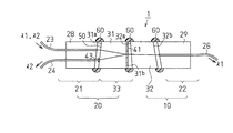
FIG. 1 shows the structure of a wavelength division multiplexing
この波長多重光カプラ1は、複数の波長(本例では2波長λ1,λ2)の光信号が多重化された入射光(波長多重信号)が1本の入射光用光ファイバ23から入射されたとき、その入射光を波長毎の光信号に分離(分波)して、2つの出射光用光ファイバ26,24に振り分ける2波長用の波長多重光カプラである。
In this wavelength multiplexing
この波長多重光カプラ1は、入射光に含まれる第1の波長λ1の光を反射し第2の波長λ2の光を透過する第1の光学フィルタ41が第2の端面である第2面31bに直接成膜により形成された第1のレンズとしての屈折率分布型ロッドレンズ31を備える。また、波長多重光カプラ1は、第1の光学フィルタ41で反射された第1の波長λ1の光が屈折率分布型ロッドレンズ31(以下、「第1のレンズ」という)を介して集光される位置に端面が位置するように配置された第1の出射光用光ファイバ24を備える。また、波長多重光カプラ1は、第1のレンズ31の第1の端面である第1面31aに直接成膜により形成された第2の光学フィルタ43と、第1の光学フィルタ41を透過した第2の波長λ2の光を集光する第2のレンズとしての屈折率分布型ロッドレンズ32とを備える。さらに、波長多重光カプラ1は、第2の波長λ2の光が屈折率分布型ロッドレンズ(以下、「第2のレンズ」という)32を介して集光される位置に端面が位置するように配置された第2の出射光用光ファイバ26を備える。
In this wavelength division multiplexing
波長多重光カプラ1では、入射光用光ファイバ(共通ポート)23から出射される2波長(1310nmと1550nmの2波長)の光信号が多重化された入射光が、第1のレンズ31の第1面31aに入射する。この波長多重光カプラ1は、入射光を2波長に分離し、1310nmの光信号を第1の出射光用光ファイバ(第2ポート)24から、1550nmの光信号を第2の出射光用光ファイバ(第1ポート)26からそれぞれ出射するようになっている。以下、第1の波長λ1を1310nm、第2の波長λ2を1550nmとして説明する。また以下の説明で、入射光用光ファイバ23と2つの出射光用光ファイバ26,24を、それぞれ光ファイバ23,24,26と呼ぶ。
In the wavelength division multiplexing
光ファイバ23と光ファイバ24は、円柱状ガラスに2つの細孔を貫通して設けた保持部材としてのキャピラリ28によって、各々の光軸(コア中心軸)が互いに平行になるように保持され、いわゆる2芯光ファイバピッグテール21を構成している。この2芯光ファイバピッグテール21の端面に対向して、第1のレンズ31が配置されている。2芯光ファイバピッグテール21と第1のレンズ31の対向する各端面は、該各端面での反射光が光ファイバ23へ戻らないように光軸に対して4〜8°程度傾斜した斜め面となっている。また、これらの各端面は、ほぼ平行であることが組立上好ましい。
The
第1のレンズ31は、光ファイバ23から出射し第1面31aから入射した入射光を平行光に変換し、かつ第2面31bの光学フィルタ41で反射される平行光を集光して光ファイバ24に結合する役割を果たす。すなわち、2芯光ファイバピッグテール21と第1のレンズ31との組み合わせで、2芯光ファイバコリメータ20が構成されている。
The
一方、1本の光ファイバ26は、光ファイバ23,24と同様に、保持部材としてのキャピラリ29によって保持され、単芯光ファイバピッグテール22を構成している。この単芯光ファイバピッグテール22の端面に対向して、第2のレンズ32が配置される。単芯光ファイバピッグテール22と第2のレンズ32の対向する各端面は、該各端面での反射光が光ファイバ23へ戻らないように光軸に対して4〜8°程度傾斜している。また、これらの各端面は、ほぼ平行であることが組立上好ましい。
On the other hand, one
この第2のレンズ32は、単芯光ファイバピッグテール22に対向する端面(第4の端面32b)とは反対側の端面(第3の端面)32aから入射する平行光を集光して光ファイバ26に結合する役割を果たす。すなわち、単芯光ファイバピッグテール22と第2の
レンズ32との組み合わせで、単芯光ファイバコリメータ10が構成されている。
The
2芯光ファイバコリメータ20と単芯光ファイバコリメータ10は、平行光が結合できるように、第1のレンズ31の第2面31bと第2のレンズ32の第3の端面32aとを対向させて配置されている。
The two-core
本例の波長多重光カプラ1では、配置する位置によって2つのフィルタ群に分けられる光学フィルタとして2枚のエッジフィルタが使用される。第1のフィルタ群に属する第1の光学フィルタ41は、第1のレンズ31と第2のレンズ32の間に設けられる。第2のフィルタ群に属する第2の光学フィルタ43は、第1のレンズ31と光ファイバ24の間に設けられる。第1の光学フィルタ41,第2の光学フィルタ43は、第1のレンズ31の第2面31b,第1面31aにそれぞれ直接成膜され、フィルタ付レンズ33として一体化されている。第2の光学フィルタ43は、光ファイバ24へ結合する光にだけ作用し、光ファイバ23から入射する光には作用しない位置に形成されている。
In the wavelength division multiplexing
ここで、第1のフィルタ群に属する第1の光学フィルタ41は、第1の波長λ1の光を反射し、第2の波長λ2の光を透過する。この光学フィルタ41は、波長λ2の透過光が反射光に対して40dB以上のアイソレーションをとれるように設計するが、実際にはこの光学フィルタ41によって反射される光には透過波長域の残留反射成分が存在するため、反射ポートにおける波長λ1の光と波長λ2の光に対するアイソレーションは12dB程度である。ここにいう「反射光のアイソレーション」とは、第1の光学フィルタ41で反射される第1の波長λ1の光に、その波長λ1以外の波長の光が混入する量がどの程度かを示す漏話阻止量をいう。なお、以下の説明で「反射光のアイソレーション」を「反射アイソレーション」と呼ぶ。
Here, the first
一方、第2の光学フィルタ43は、第1の波長λ1の光を透過し、第2の波長λ2の光を反射する。この光学フィルタ43は、図2(a),(b)に示すように、第1のレンズ31の第1面31a上の、第1の光学フィルタ41からの反射光が通過する出射光通過領域52に形成されており、光ファイバ23からの出射光が通過する入射光通過領域51には形成されていない。第2の光学フィルタ43は、第1の光学フィルタ41と重ねて設けられているため(つまり光学フィルタ41からの反射光が第2の光学フィルタ43に入射する構成であるため)、光学フィルタ41より特性が劣るものでよい。全体で40dB以上のアイソレーションを得るためには、上記反射アイソレーションが12dB程度であるので、透過光のアイソレーションは30dB以下でよく、安価な光学フィルタを用いることができる。ここにいう「透過光のアイソレーション」とは、第2の光学フィルタ43を透過する第1の波長λ1の光に、その波長λ1以外の波長の光が混入する量がどの程度かを示す漏話阻止量をいう。なお、以下の説明で「透過光のアイソレーション」を「透過アイソレーション」と呼ぶ。
On the other hand, the second
また、光ファイバ23からの出射光が入射するレンズ31の第1面31aには、反射による損失を低減するための反射防止膜50が設けられている(図2(a),(b)参照)。この反射防止膜50は、1250nmから1650nmの全波長域にわたって反射率が0.5%以下となるような特性を有する。また、この反射防止膜50は、図2(a),(b)に示すように、第1のレンズ31の第1面31a上の入射光通過領域51に形成されており、出射光通過領域52には形成されていない。
Further, an
第1のレンズ31の第1面31aに形成されている第2の光学フィルタ43と反射防止膜50は異なる膜構成となるため、通常成膜は別々に他方を遮蔽して行う必要がある。ただし、第1面31aにおいて、光ファイバ23からの出射光が通過する入射光通過領域51と光学フィルタ41からの反射光が通過する出射光通過領域52は僅か100μm程度
しか離れていない。そのため、治具等による遮蔽(マスキング)は、成膜時に自然加熱された際に、その遮蔽部に熱膨張による変形が生じるなど位置精度の問題があり、困難である。
Since the second
そこで、本例では、その遮蔽を遮蔽膜の塗布によって行う、いわゆるリフトオフ法を用いる。すなわち、誘電体多層膜である第2の光学フィルタ43を形成しない部分に樹脂等を塗布して遮蔽(マスキング)し、その上に誘電体多層膜を成膜する。次いで下地の樹脂(遮蔽部)を溶解して誘電体多層膜と共に除去し、第1面31aの一部分にのみ誘電体多層膜を付着させる。反射防止膜50を誘電体多層膜上に形成する場合についても同様の手順を繰り返す。
Therefore, in this example, a so-called lift-off method in which the shielding is performed by applying a shielding film is used. That is, a resin or the like is applied to a portion where the second
上記構成を有する波長多重光カプラ1では、2芯光ファイバピッグテール21とフィルタ付レンズ33は、微小な間隙を残したまま、周囲をエポキシ樹脂60で固定されている(図1参照)。また、第1の光学フィルタ41を透過した第2の波長λ2の光が最小損失で光ファイバ26に結合するように、単芯光ファイバピッグテール22を調芯した後、第2のレンズ32と単芯光ファイバピッグテール22は、微小な間隙を残したまま、周囲をエポキシ樹脂60で固定されている(図1参照)。
In the wavelength multiplexing
また、波長多重光カプラ1は、図1に示すように全部品を調芯してエポキシ樹脂60で固定する作業が終了した後、保護用のケース(ハウジング)を被せて最終形態とするのが望ましい。そのケースの外形は小型の管状とすることができ、この場合その直径が数mm、長さが数10mmである。
In addition, the wavelength division multiplexing
上記波長多重光カプラ1の製造方法は、次の点に特徴がある。つまり、第2の光学フィルタ43を、第1のレンズ31の第1面31a上の出射光通過領域52に形成し、入射光通過領域51には形成しないようにする。反射防止膜50を、第1面31a上の入射光通過領域51に形成し、出射光通過領域52には形成しないようにする。
The manufacturing method of the wavelength multiplexing
波長多重光カプラの製造方法は、以下の工程を含む。
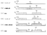
(工程1)第1のレンズ31の第1面31a上の入射光通過領域51をマスクする工程(図3(a)参照)。この工程では、図3(a)および図4(a)に示すように、入射光通過領域51のみを覆うように遮蔽材料53を塗布する。
The manufacturing method of the wavelength multiplexing optical coupler includes the following steps.
(Step 1) A step of masking the incident
(工程2)遮蔽材料53で入射光通過領域51がマスクされた第1面31aに、誘電体多層膜54を成膜する工程(図3(b)参照)。
(工程3)マスクとしての遮蔽材料53を該遮蔽材料53上に成膜された誘電体多層膜54と共に除去する工程(図3(c)参照)。
(Step 2) A step of forming a
(Step 3) A step of removing the shielding
(工程4)第1面31a上に成膜された誘電体多層膜54上の、出射光通過領域52をマスクする工程(図3(d)参照)。この工程では、図3(d)および図4(b)に示すように、出射光通過領域52のみを覆うように遮蔽材料55を塗布する。
(Step 4) A step of masking the outgoing
(工程5)出射光通過領域52がマスクされた誘電体多層膜54上に、反射防止膜50を成膜する工程(図3(e)参照)。
(工程6)マスクとしての遮蔽材料55をその上に成膜された反射防止膜50と共に除去する工程(図3(f)参照)。
(Step 5) A step of forming an
(Step 6) A step of removing the shielding
以上の工程により、第2の光学フィルタ43は、第1のレンズ31の第1面31a上の出射光通過領域52に形成され、入射光通過領域51には形成されない。また、反射防止膜50は、第1面31a上の入射光通過領域51に形成され、出射光通過領域52には形
成されない。
Through the above steps, the second
次に、上記一実施形態の各実施例を説明する。
(実施例)
各実施例の波長多重光カプラ1では、管状である保護用のケース(図示省略)の直径を5.5mmとし、その長さを約40mmとした。また、この波長多重光カプラ1では、光通信規格B−PONに準拠した以下の特性を目標仕様とした。
Next, examples of the one embodiment will be described.
(Example)
In the wavelength division multiplexing
透過アイソレーション 40dB 以上(波長域:1260-1360, 1480-1500nm )
反射アイソレーション 40dB 以上(波長域:1550-1565nm )
透過挿入損失 0.7dB 以下(波長域:1260-1360, 1480-1500nm )
反射挿入損失 0.7dB 以下(波長域:1550-1565nm )
偏波依存損失 0.2dB 以下(上記全波長域で)
各実施例の波長多重光カプラ1では第1の光学フィルタ41として、直径1.8mmの屈折率分布型ロッドレンズで構成した第1のレンズ31の第2面31bに、1310nm帯,1490nm帯の光を反射し、かつ1530nm帯の光を透過する波長特性のエッジフィルタを形成した。このエッジフィルタは、SiO2とTiO2を交互に多数積層した誘電体多層膜である。
Transmission isolation 40dB or more (wavelength range: 1260-1360, 1480-1500nm)
Reflection isolation 40dB or more (wavelength range: 1550-1565nm)
Transmission insertion loss 0.7dB or less (wavelength range: 1260-1360, 1480-1500nm)
Reflection insertion loss 0.7dB or less (wavelength range: 1550-1565nm)
Polarization-dependent loss 0.2 dB or less (in all the above wavelength ranges)
In the wavelength multiplexing
次いで、図2(a),(b)に示すように、第1のレンズ31の第1面(斜め面)31a上の入射光通過領域51を除いた部分で、少なくとも出射光通過領域52に、1310nm帯,1490nm帯の光をそれぞれ透過し、かつ1530nm帯の光を反射する波長特性の誘電体多層膜43Aを形成した。この誘電体多層膜43Aは、高屈折率材料のTiO2を主成分とする高屈折率誘電体膜と、低屈折率材料のSiO2を主成分とする低屈折率誘電体膜とを交互に交互に積層した誘電体多層膜で、つぎの4通りの膜構成のもの(実施例1〜実施例4)を作製した。
Next, as shown in FIGS. 2A and 2B, at least in the outgoing
(実施例1)
実施例1の詳細な膜構成を下記の表1に示す。また、この誘電体多層膜の理論光学特性を図8の曲線64に示す。図9の曲線66は実施例1の偏波依存損失を示している。
Example 1
The detailed film configuration of Example 1 is shown in Table 1 below. The theoretical optical characteristic of this dielectric multilayer film is shown by a

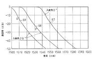
図10は、実施例1の偏波依存性のシミュレーション値を示している。図10で、曲線67は入射角0°での特性を示し、曲線68と曲線69は、入射角20°での偏光のP成分の特性とそのS成分の特性をそれぞれ示している。
FIG. 10 shows the simulation value of the polarization dependence of the first embodiment. In FIG. 10, a
(実施例2)
実施例2の詳細な膜構成を下記の表2に示す。また、この誘電体多層膜の理論光学特性は図8の曲線64で示す特性と同様であり、図示を省略する。図9の曲線65は実施例2の偏波依存損失(PDL)を示している。この図9から、実施例2の偏波依存損失が実施例1よりも小さいことが分かる。
(Example 2)
The detailed film configuration of Example 2 is shown in Table 2 below. The theoretical optical characteristics of the dielectric multilayer film are the same as the characteristics indicated by the
図11は、実施例2における第2の光学フィルタ43の偏波依存性のシミュレーション値を示している。図11で、曲線70は入射角0°での特性を示し、曲線71と曲線72は、入射角20°での偏光のP成分の特性とそのS成分の特性をそれぞれ示している。
FIG. 11 shows a simulation value of the polarization dependence of the second
図10と図11を比較すると、実施例2の方が実施例1よりも、偏光分離(偏波依存性)の度合が小さくなることが分かる。
このように実施例2では、第1の光学フィルタ41,第2の光学フィルタ43が第1のレンズ31の第2面31b,第1面31aにそれぞれ成膜されたフィルタ付レンズ33が作製される。このフィルタ付レンズ33の測定結果を図12(a),(b)に示す。図12(a),(b)の縦軸は挿入損失の逆数である。すなわち入射ポートに入射した光の強度に対して反射ポートおよび透過ポートで観測される光の強度の比をdB単位で示している。図12(b)は図12(a)の損失の小さい部分を拡大したものである。
Comparing FIG. 10 and FIG. 11, it can be seen that the degree of polarization separation (polarization dependence) is smaller in the second embodiment than in the first embodiment.
Thus, in Example 2, the
図12(a),(b)の曲線73は、透過光出射ポート(上記実施形態の光ファイバ26)から出射される光の強度を示しており、上記λ2に相当する1550nm帯の光の強度とλ1に相当する1310nm帯または1490nm帯の光の強度の比は40dB以上に達しており、上記透過アイソレーションの目標仕様が達成されていることがわかる。また図12(b)によれば1550nm帯における挿入損失は0.2〜0.3dB程度であり、上記透過挿入損失の目標仕様も満たされていることがわかる。
一方、曲線74は反射光出射ポート(同実施形態の光ファイバ24)から出射される光の強度を示しており、上記λ1に相当する1310nm帯または1490nm帯の光の強度とλ2に相当する1550nm帯の光の強度との比は40dB以上に達しており、上記反射アイソレーションの目標仕様が達成されていることが分かる。また、図12(b)に
よれば1310nm帯または1490nm帯における挿入損失は0.3〜0.7dB程度であり、上記透過挿入損失の目標仕様も満たされていることがわかる。
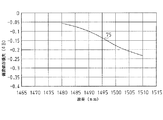
On the other hand, a
また、実施例2の第2の光学フィルタ43の偏波依存損失の測定結果を図13に示す。この図13から、上記目標仕様(偏波依存損失の目標仕様)が達成されていることが分かる。
Moreover, the measurement result of the polarization dependence loss of the 2nd
(実施例3)
実施例3の波長多重光カプラ1では、上記実施例1と同様に上記の特性を目標仕様とした。実施例3では、エッジフィルタである第2の光学フィルタ43の誘電体多層膜54は、TiO2を主成分とする高屈折率誘電体膜と、SiO2を主成分とする低屈折率誘電体膜とを交互に49層積層した誘電体多層膜である(下記の表3参照)。この誘電体多層膜54の膜構成は、高屈折率誘電体膜の光学膜厚をλ/4とし、低屈折率誘電体膜の光学膜厚を3λ/4としている。この誘電体多層膜の理論特性を図14の曲線76で示す。
(Example 3)
In the wavelength division multiplexing
図10と図15を比較すると、実施例3の方が実施例1よりも、偏光分離(偏波依存性)の度合が小さくなることが分かる。このように、実施例3の第2の光学フィルタ43でも、偏光分離が明らかに改善されており、上記目標仕様(偏波依存損失の目標仕様)が達成されている。
Comparing FIG. 10 and FIG. 15, it can be seen that the degree of polarization separation (polarization dependence) is smaller in the third embodiment than in the first embodiment. Thus, also in the second
(実施例4)
実施例4の波長多重光カプラ1では、上記実施例1と同様に上記の特性を目標仕様とした。実施例4では、エッジフィルタである第2の光学フィルタ43の誘電体多層膜54は、TiO2を主成分とする高屈折率誘電体膜と、SiO2を主成分とする低屈折率誘電体膜とを交互に49層積層した誘電体多層膜である(下記の表4参照)。この誘電体多層膜の膜構成は、高屈折率誘電体膜の光学膜厚を3λ/4とし、低屈折率誘電体膜の光学膜厚をλ/4としている。この誘電体多層膜の理論特性を図16の曲線80で示す。
Example 4
In the wavelength division multiplexing
図10と図17を比較すると、実施例4の方が実施例1よりも、偏光分離(偏波依存性)の度合が共に小さくなることが分かる。このように、実施例4の第2の光学フィルタ43でも、偏光分離が明らかに改善されており、上記目標仕様(偏波依存損失の目標仕様)が達成されている。
Comparing FIG. 10 and FIG. 17, it can be seen that the degree of polarization separation (polarization dependence) is smaller in Example 4 than in Example 1. Thus, also in the second
また、実施例4における第2の光学フィルタ43によれば、図17から明らかなように、入射角による波長変動量を上記各実施例よりも更に少なくすることができる。これにより、上記第1のレンズ31の第1面(斜め面)31aに第1の光学フィルタ41で反射された収束光が入射する際に発生するエッジ波長付近での波長特性の鈍りによる偏光分離(偏波依存損失)の生じる波長帯域を狭めることができる。
Further, according to the second
以上説明したように、エッジフィルタである一実施形態に係る第2の光学フィルタ43は、高屈折率材料のTiO2を主成分とする高屈折率誘電体膜と、低屈折率材料のSiO2を主成分とする低屈折率誘電体膜とを交互に多数積層した誘電体多層膜54である。この誘電体多層膜54の膜構成の特徴は、高屈折率誘電体膜と低屈折率誘電体膜のいずれか一方或いは両方の光学膜厚を3λ/4とした点にある。
As described above, the second
以上のように構成された一実施形態によれば、以下の作用効果を奏する。
○一般に、波長多重光カプラに屈折率分布型ロッドレンズを用いる場合、入射ポートの光ファイバからの入射光が同レンズの入射面で反射されて入射ポートへ戻るのを(リターンロスを)抑制するために、その入射面が斜めに加工されている。この斜め面に成膜される光学フィルタは偏波依存性が大きい。屈折率分布型ロッドレンズの入射面と反対側の出射面から出射する光はコリメートされ広がりをもった平行光である。一方、その平行光に含まれる特性波長の光が光学フィルタで反射されて入射面から出射する光は、出射ポートの光ファイバとの結合のため収束光となっている。このため、斜め面である入射面に成膜された光学フィルタの膜面に対して斜めに入射する斜め入射成分が増大し、これによりその光学フィルタでは、エッジ波長付近で大きな偏波依存性が生じる。エッジ波長のシフトに伴うエッジ波長付近での波長特性の鈍りが偏波依存性低減の支障となっていた。
According to the embodiment configured as described above, the following operational effects can be obtained.
In general, when a gradient index rod lens is used for a wavelength multiplexing optical coupler, the incident light from the optical fiber of the incident port is reflected from the incident surface of the lens and returned to the incident port (return loss) is suppressed. Therefore, the incident surface is processed obliquely. The optical filter formed on the oblique surface has a large polarization dependency. The light emitted from the exit surface opposite to the entrance surface of the gradient index rod lens is collimated and spread parallel light. On the other hand, light having a characteristic wavelength included in the parallel light is reflected by the optical filter and emitted from the incident surface is converged light due to coupling with the optical fiber of the emission port. For this reason, the oblique incident component that is obliquely incident on the film surface of the optical filter formed on the incident surface that is an oblique surface increases, and the optical filter has a large polarization dependence near the edge wavelength. Arise. The dullness of the wavelength characteristics near the edge wavelength accompanying the shift of the edge wavelength has been an obstacle to reducing the polarization dependence.
これに対して、第1実施形態によれば、屈折率分布型ロッドレンズで構成される第1のレンズ31の斜め面である第1面31aに形成される第2の光学フィルタ43の誘電体多層膜54は、高屈折率誘電体膜と低屈折率誘電体膜のいずれか一方或いは両方の光学膜厚を3λ/4としている。これにより、第2の光学フィルタ43における偏波依存損失(PDL)を低減でき、同光学フィルタの波長特性におけるエッジ波長近傍でも偏波依存性を低減することができる。
On the other hand, according to the first embodiment, the dielectric of the second
○第1のレンズ31の第1面31aに第1の波長λ1の光を透過しそれ以外の波長の光を反射する第2の光学フィルタ43を設けたことにより、第1の光学フィルタ41からの反射光中に存在する残留反射成分を除去できる。これにより、第2の光学フィルタ43の透過光(第1波長λ1の光)にその波長以外の光が混入する量が低減される。したがって、第1の光学フィルタ41の反射光を利用するポートのアイソレーションが改善される。つまり、第2の光学フィルタ43を透過して第1の出射光用光ファイバ24に結合する透過光のアイソレーションを高くすることができる。なお、第2の光学フィルタ43の理論特性を図6の曲線62で示す。
The first
○第1のレンズ31は第1面31aと第2面31bを有する屈折率分布型ロッドレンズとし、入射光用光ファイバ23と第1の出射光用光ファイバ24は、該各光ファイバのコア中心軸が互いに平行になるようにキャピラリ28に保持されている。これにより、第1のレンズ31、入射光用光ファイバ23、および第1の出射光用光ファイバ24をほぼ直線上に配置することができ、小型で組立てが容易な波長多重光カプラ1を実現することができる。
The
○第1の光学フィルタ41は、第1のレンズ31の第2面31bに密着されている。これによれば、第1のレンズ31を構成する屈折率分布型ロッドレンズは光が入射する端面および出射する端面を平面とすることができるため、同ロッドレンズの第2面31bに平板状の光学フィルタ41を密着させることが容易である。また、屈折率分布型ロッドレンズは、その端面をその光軸に対して傾斜するように加工することが容易であり、第2面31bに光学フィルタ41を密着させることにより、光学フィルタ41の角度が容易に調整できる。また、光学フィルタ41が屈折率分布型ロッドレンズの第2面31bに密着したフィルタ付レンズ33を用いることにより、部品点数が減るので、組立てが容易な波長多重光カプラ1を実現することができる。
The first
○第2のフィルタ群に属する第2の光学フィルタ43を誘電体多層膜とし、該誘電体多層膜が第1のレンズ31の第1面31aに直接成膜して形成されている。これによれば、波長多重光カプラ1の組立てが大幅に容易になる。
The second
○入射光用光ファイバ23と第1の出射光用光ファイバ24が保持部材としてのキャピラリ28で保持された2芯光ファイバピッグテール21を構成することにより、これらの光ファイバ23,24の取り扱いおよび調芯が容易になる。
By configuring the two-core
○第1の光学フィルタ41を透過して第3の端面32aから入射する入射光を、第4の端面32bから出射して集光する第2のレンズ32と、該レンズ32により集光された位置に端面が位置するように配置された第2の出射光用光ファイバ26とを含むので、第1の光学フィルタ41を透過した光も利用することができる。なお、第1の光学フィルタ41の理論特性を図5の曲線61で示す。
The incident light that has passed through the first
○第1の波長λ1は1260〜1360nm、1480〜1500nmの波長範囲とし、第2の波長λ2は1550〜1560nmの波長範囲とすることで、FTTx用等の上り下り信号とアナログ画像信号を、既設の光ファイバ網に適合した波長域で伝送することが可能となる。 ○ The first wavelength λ1 is in the range of 1260 to 1360 nm and the wavelength range of 1480 to 1500 nm, and the second wavelength λ2 is in the wavelength range of 1550 to 1560 nm. It is possible to transmit in a wavelength range suitable for the optical fiber network.
○第1のレンズ31の第1面31aには、第2の光学フィルタ43と反射防止膜50が直接成膜により形成されている。反射防止膜50は、第1面31a上の、入射光用光ファイバ23の端面から出射される入射光が通過する入射光通過領域51に形成されており、該入射光通過領域51には第2の光学フィルタ43は形成されていない。また、第2の光
学フィルタ43は、第1面31a上の、第1の光学フィルタ41からの反射光が通過する出射光通過領域52に形成されており、該出射光通過領域52には反射防止膜50は形成されていない。このような構成により、2種類の波長λ1,λ2の光信号が多重化された入射光が入射光用光ファイバ23から出射されて入射する第1のレンズ31の第1面31aには、反射防止膜50が形成されているので、入射光が入射光用光ファイバ23へ戻るのを抑制できると共に、入射光の反射損失を低減することができる。また、反射防止膜50は第1のレンズ31の第1面31aにおける入射光通過領域51に形成され、出射光通過領域52には形成されていないので、第2の光学フィルタ43の特性には影響を及ぼさない。また、第2の光学フィルタ43は、第1の光学フィルタ41により分波された光のうち、第1の波長λ1の光を透過してそれ以外の波長成分を反射することで、第1の出射光用光ファイバ24に結合される出射光のアイソレーションを向上させるが、入射光には影響を及ぼさない。なお、反射防止膜50の理論特性を図8の曲線64で示す。
On the
○エッジフィルタである第2の光学フィルタ43は、TiO2を主成分とする高屈折率
誘電体膜と、SiO2を主成分とする低屈折率誘電体膜とを交互に49層積層した誘電体
多層膜である。この誘電体多層膜の膜構成は、高屈折率誘電体膜と低屈折率誘電体膜の両方の光学膜厚を3λ/4としている。このような構成により、第2の光学フィルタ43における偏波依存損失(PDL)を低減でき、同光学フィルタ43の波長特性におけるエッジ波長近傍でも偏波依存性を低減することができる。
The second
なお、この発明は以下のように変更して具体化することもできる。
・上記第1実施形態では、第2の光学フィルタ43を第1のレンズ31の第1面31a側に成膜し、その上に反射防止膜50を成膜している(図2(a)参照)が、反射防止膜50を第1面31a側に成膜し、その上に第2の光学フィルタ43を成膜する構成にも本発明は適用可能である。この場合にも、第2の光学フィルタ43は、第1面31a上の出射光通過領域52に形成し、入射光通過領域51には形成しないようにする。また、反射防止膜50は、第1面31a上の入射光通過領域51に形成し、出射光通過領域52には形成しないようにする。
In addition, this invention can also be changed and embodied as follows.
In the first embodiment, the second
・上記実施形態では、第1の光学フィルタ41は第1のレンズ31の第2面31bに直接成膜したが、ガラス基板の両側端面に第1の光学フィルタを含む第1のフィルタ群を形成した光学フィルタチップを、両レンズ31,32間に固定しても良い。4種類以上の波長(4波長以上)の光の合分波を行う場合には、そのような光学フィルタチップの仕様は必須となる。
In the above embodiment, the first
・上記各実施形態では、第2の光学フィルタ43と反射防止膜50が第1のレンズの第1面31aの全面に成膜されて直付けされた構成例を説明したが、本発明はこのような構成に限定されない。例えば、第2の光学フィルタ43を含む第2のフィルタ群を構成する「光学フィルタ素子」が、第1の出射光用光ファイバ24の端面と第1面31aの間で、入射面が入射光の光軸に対して傾斜して配置されている。そして、この光学フィルタ素子は、第2のフィルタ群に加えて反射防止膜50を備える。このような構成の波長多重光カプラにも本発明は適用可能である。
In each of the above embodiments, the second
・上記実施形態において、1550nmの光信号を第1の出射光用光ファイバ(第2ポート)24から、1310nmまたは1490nmの光信号を第2の出射光用光ファイバ(第1ポート)26からそれぞれ出射するように構成してもよい。 In the above embodiment, a 1550 nm optical signal is output from the first outgoing optical fiber (second port) 24, and a 1310 nm or 1490 nm optical signal is output from the second outgoing optical fiber (first port) 26. You may comprise so that it may radiate | emit.
・また、各光学フィルタ41,43をバンドパスフィルタを使用して構成することも可能である。もちろん、使用波長は上記実施形態における2波長(λ1、λ2)には限られず、3波長以上であってもよい。例えば、1260〜1360nm,1480〜1500
nm,1550〜1560nmの波長範囲から各波長を選択することもできる。
The optical filters 41 and 43 can be configured using band pass filters. Of course, the wavelength used is not limited to the two wavelengths (λ1, λ2) in the above embodiment, and may be three or more wavelengths. For example, 1260-1360 nm, 1480-1500
Each wavelength can also be selected from a wavelength range of nm and 1550 to 1560 nm.
・光学フィルタ43は、光ファイバ24へ結合する光にだけ作用し、光ファイバ23から入射する光には作用しないような形状であれば、どのような形状でもよい。
・上記実施形態では、波長多重光カプラ1は、波長多重光を分波する光分波器の構成について説明したが、まったく同じ構成の波長多重光カプラは2波長の光信号を多重化して1本の光ファイバに結合する合波器としても使用できる。この場合は、入射光用光ファイバ23が出射光用光ファイバとなり、各出射光用光ファイバがそれぞれ入射光用光ファイバとなる。
The
In the above embodiment, the wavelength multiplexing
・上記実施形態で説明した波長多重光カプラは、OLT、ONUに組み込みことができるだけでなく、(O/E)変換器、(E/O)変換器等、他の光電子デバイスに広く適用可能である。 The wavelength multiplexing optical coupler described in the above embodiment can be incorporated not only in the OLT and ONU but also widely applicable to other optoelectronic devices such as (O / E) converters and (E / O) converters. is there.
・上記実施形態では、第1のフィルタ群に属する光学フィルタとして、第1の光学フィルタ41のみを用いた構成について説明したが、第1のフィルタ群が、平行光の進行方向に沿って透過波長範囲が順に狭くなるように配列された複数の光学フィルタを含む構成にも本発明は適用可能である。この場合、第1のフィルタ群の複数の光学フィルタは、第1のレンズ31から出射される平行光に含まれる複数の波長の光信号をそれぞれ異なる方向に反射するように、第1のレンズ31の光軸に対してそれぞれ異なる角度をなすように第2面31b側に配置される。また、この場合、第1の出射光用光ファイバ24に代えて、第1のフィルタ群の各光学フィルタからの反射光がそれぞれ結合する位置に端面が位置するように複数の光ファイバが配置される。これによれば、3種類以上の波長の光信号が多重化された入射光(波長多重信号)から各波長毎に光信号を分離して対応する各ポートの光ファイバに振り分けることができる。
In the above embodiment, the configuration using only the first
また、前記第1のフィルタ群における複数の光学フィルタのうち、第2面31bに最も近い位置に配置される光学フィルタ、例えば光学フィルタ41は第2面31bに密着させる。これによれば、第1のレンズ31を構成する屈折率分布型ロッドレンズは光が入射する端面および出射する端面を平面とすることができるため、同ロッドレンズの第2面に平板状の光学フィルタを密着させることが容易である。また、同ロッドレンズの端面をその光軸に対して傾斜するように加工することが容易であり、その第2面に光学フィルタを密着させることにより、光学フィルタの角度が容易に調整できる。また、光学フィルタがロッドレンズの端面に密着したフィルタ付きロッドレンズを用いることにより、部品点数が減るので、組立てが容易な波長多重光カプラを実現することができる。
In addition, among the plurality of optical filters in the first filter group, an optical filter disposed at a position closest to the
・上記実施形態では、第2のフィルタ群に属する第2の光学フィルタ43を誘電体多層膜とし、該誘電体多層膜を第1のレンズの第1面31aに直接成膜して形成してあるが、第2の光学フィルタ43を第1の出射光用光ファイバ24の端面に直接成膜して形成した構成にも本発明は適用可能である。
In the above embodiment, the second
・上記実施形態では、入射光用光ファイバ23と第1の出射光用光ファイバ24が保持部材としてのキャピラリ28で保持された2芯光ファイバピッグテール21を用いた構成について一例として説明したが、3本以上の光ファイバがキャピラリ28に保持された多芯光ファイバピッグテールを用いた構成にも本発明は適用可能である。また、単芯光ファイバピッグテール22に代えて、2本以上の光ファイバがキャピラリ29に保持された多芯光ファイバピッグテールを用いた構成にも本発明は適用可能である。
In the above-described embodiment, the configuration using the two-core
・上記実施形態において、第2のレンズ32は、第3の端面(第3面)32aと第4の端面(第4面)32bを有する第2の屈折率分布型ロッドレンズとし、第1のフィルタ群
における複数の光学フィルタのうち、第3の端面32aに最も近い位置に配置される光学フィルタは、第3の端面32aに密着させる。このような構成の波長多重光カプラにも本発明は適用可能である。これによれば、第2のレンズ32の第3の端面に平板状の光学フィルタを密着させることが容易である。また、同レンズの第3の端面に光学フィルタを密着させることにより、光学フィルタの角度が容易に調整できる。また、光学フィルタが第3の端面に密着したフィルタ付きロッドレンズを用いることにより、部品点数が減るので、組立てが更に容易な波長多重光カプラを実現することができる。
In the above embodiment, the
・第2のレンズ32である第2の屈折率分布型ロッドレンズの第3の端面32aに密着させた光学フィルタを誘電体多層膜とし、該誘電体多層膜を第3の端面に直接成膜して形成するようにしてもよい。これによれば、第2の屈折率分布型ロッドレンズの第3の端面に誘電体多層膜である光学フィルタを直接成膜して形成することにより、フィルタ付きロッドレンズを大量に生産するのが容易になる。
The optical filter in close contact with the third end face 32a of the second gradient index rod lens as the
λ1…第1の波長、λ2…第2の波長、1…波長多重光カプラ、23…入射光用光ファイバ、24…第1の出射光用光ファイバ、26…第2の出射光用光ファイバ、31…屈折率分布型ロッドレンズ(第1のレンズ)、31a…第1の端面である第1面、31b…第2の端面である第2面、32…屈折率分布型ロッドレンズ(第2のレンズ)、32a…第3の端面、32b…第4の端面、41…第1の光学フィルタ、43…第2の光学フィルタ、50…反射防止膜、51…入射光通過領域、52…出射光通過領域、54…誘電体多層膜。 λ1 ... first wavelength, λ2 ... second wavelength, 1 ... wavelength multiplexed optical coupler, 23 ... incident light optical fiber, 24 ... first outgoing light optical fiber, 26 ... second outgoing light optical fiber , 31 ... gradient index rod lens (first lens), 31a ... first surface as a first end surface, 31b ... second surface as a second end surface, 32 ... gradient index rod lens (first lens) 2 lens), 32a ... third end face, 32b ... fourth end face, 41 ... first optical filter, 43 ... second optical filter, 50 ... antireflection film, 51 ... incident light passing region, 52 ... Emission light passage region, 54... Dielectric multilayer film.
Claims (10)
前記誘電体多層膜は高屈折率誘電体膜と低屈折率誘電体膜とが交互に多数積層され、前記高屈折率誘電体膜と低屈折率誘電体膜のいずれか一方或いは両方の光学膜厚を3λ/4としたことを特徴とする光学フィルタ。 In an optical filter composed of a dielectric multilayer film that is fixed with the incident surface inclined with respect to the optical axis of the incident light,
The dielectric multilayer film includes a plurality of high refractive index dielectric films and low refractive index dielectric films alternately stacked, and one or both of the high refractive index dielectric films and the low refractive index dielectric films. An optical filter having a thickness of 3λ / 4.
前記誘電体多層膜は、入射面と出射面の少なくとも一方が斜め面に形成された屈折率分布型ロッドレンズの前記斜め面に形成されたことを特徴とする光学フィルタ。 The optical filter according to claim 1,
The optical filter, wherein the dielectric multilayer film is formed on the oblique surface of a gradient index rod lens in which at least one of an entrance surface and an exit surface is formed on an oblique surface.
前記入射光用光ファイバから出射され第1面から入射する前記入射光を平行光に変換して第2面から出射する第1のレンズと、該レンズの前記第2面側に配置され、前記複数の波長のうち第1の波長の光を反射する第1の光学フィルタを含む第1のフィルタ群と、前記第1の光学フィルタにより反射された平行光が前記第1面から出射して集光される位置に端面が位置するように配置された第1の出射光用光ファイバと、該光ファイバの端面と前記第1面の間に配置され、第1の波長の光を透過しそれ以外の波長の光を反射する第2の光学フィルタを含む第2のフィルタ群を構成する光学フィルタ素子と、を備え、
前記光学フィルタ素子はその入射面が前記入射光の光軸に対して傾斜して配置され、前記第2のフィルタ群に加えて反射防止膜を備え、該反射防止膜は、前記入射光用光ファイバの端面から出射される前記入射光が通過する入射光通過領域に形成されており、
前記第2の光学フィルタは、前記第1の光学フィルタからの反射光が通過する出射光通過領域に形成され高屈折率誘電体膜と低屈折率誘電体膜とが交互に多数積層された誘電体多層膜であり、前記高屈折率誘電体膜と低屈折率誘電体膜のいずれか一方或いは両方の光学膜厚を3λ/4としたことを特徴とする波長多重光カプラ。 When incident light in which optical signals of a plurality of wavelengths are multiplexed is incident from a single incident light optical fiber, the incident light is separated into optical signals for each wavelength, and a plurality of outgoing light optical fibers are separated. In the wavelength division multiplexing optical coupler to distribute,
A first lens that is emitted from the incident optical fiber and is incident on the first surface and is converted into parallel light and emitted from the second surface; and is disposed on the second surface side of the lens, A first filter group including a first optical filter that reflects light having a first wavelength among a plurality of wavelengths, and parallel light reflected by the first optical filter is emitted from the first surface and collected. A first optical fiber for outgoing light arranged so that an end face is located at a position to be illuminated; and an optical fiber arranged between the end face of the optical fiber and the first face for transmitting light of a first wavelength; An optical filter element that constitutes a second filter group including a second optical filter that reflects light of a wavelength other than
The optical filter element has an incident surface inclined with respect to the optical axis of the incident light, and includes an antireflection film in addition to the second filter group, and the antireflection film includes the light for incident light. Formed in an incident light passage region through which the incident light emitted from the end face of the fiber passes,
The second optical filter is a dielectric in which a large number of high-refractive index dielectric films and low-refractive index dielectric films are alternately stacked and formed in an outgoing light passage region through which reflected light from the first optical filter passes. A wavelength-multiplexed optical coupler, wherein the optical film thickness of either one or both of the high refractive index dielectric film and the low refractive index dielectric film is 3λ / 4.
前記第1のレンズの第1面が前記入射光の光軸に対して傾斜した平面であり、前記光学フィルタ素子は前記第1面に密着して設けられていることを特徴とする波長多重光カプラ。 The wavelength division multiplexing optical coupler according to claim 3,
The wavelength multiplexed light, wherein the first surface of the first lens is a flat surface inclined with respect to the optical axis of the incident light, and the optical filter element is provided in close contact with the first surface. Coupler.
前記第1のレンズは、前記第1面に相当する第1の端面と前記第2面に相当する第2の端面とを有する屈折率分布型ロッドレンズであることを特徴とする波長多重光カプラ。 The wavelength division multiplexing optical coupler according to claim 4,
The wavelength division multiplexing optical coupler, wherein the first lens is a gradient index rod lens having a first end surface corresponding to the first surface and a second end surface corresponding to the second surface. .
前記第1のフィルタ群は、前記平行光の進行方向に沿って透過波長範囲が順に狭くなるように配列された複数の光学フィルタを含み、該複数の光学フィルタは、前記平行光に含まれる複数の波長の光信号をそれぞれ異なる方向に反射するように前記第1のレンズの光軸に対してそれぞれ異なる角度をなすように前記2面側に配置されており、前記第1の出射光用光ファイバは、前記第1のフィルタ群の各光学フィルタからの反射光がそれぞれ結合する位置に端面が位置するように配置された複数の光ファイバを含むことを特徴とする波長多重光カプラ。 In the wavelength division multiplexing optical coupler according to any one of claims 3 to 5,
The first filter group includes a plurality of optical filters arranged so that a transmission wavelength range is sequentially narrowed along a traveling direction of the parallel light, and the plurality of optical filters are included in the parallel light. Are arranged on the two surface sides so as to have different angles with respect to the optical axis of the first lens so as to reflect the optical signals of the wavelengths in the different directions, respectively, and the first outgoing light light 2. The wavelength division multiplexing optical coupler according to claim 1, wherein the fiber includes a plurality of optical fibers arranged so that end faces thereof are located at positions where reflected light from the respective optical filters of the first filter group is coupled.
前記第1のフィルタ群の全ての光学フィルタを透過して第3面から入射する入射光を、第4面から出射して集光する第2のレンズと、該第2のレンズにより集光された位置に端
面が位置するように配置された第2の出射光用光ファイバと、をさらに含むことを特徴とする波長多重光カプラ。 The wavelength division multiplexing optical coupler according to claim 6,
Incident light that passes through all the optical filters of the first filter group and enters from the third surface is collected by the second lens that is emitted from the fourth surface and collected, and the second lens. And a second optical fiber for outgoing light arranged so that the end face is located at the end position.
前記入射光用光ファイバから出射される入射光を該入射光の光軸に対して傾斜した第1面から入射し、平行光に変換して第2面から出射する第1のレンズと、該第1のレンズの第2面に対向して配置され前記平行光に変換された入射光に含まれる第1の波長の光を反射し第2の波長の光を透過する第1の光学フィルタと、前記第1の光学フィルタにより反射された第1の波長の光が前記第1のレンズを介して集光される位置に端面が位置するように配置された第1の出射光用光ファイバと、前記第1のレンズの前記第1面に直接成膜により形成され、第1の波長の光を透過しそれ以外の波長の光を反射する第2の光学フィルタと、前記第1の光学フィルタを透過した第2の波長の光を集光する第2のレンズと、前記第2の波長の光が前記第2のレンズを介して集光される位置に端面が位置するように配置された第2の出射光用光ファイバと、を備え、
前記第1のレンズの第1面には、前記第2の光学フィルタと反射防止膜が形成されており、前記反射防止膜は、前記第1面上の、前記入射光用光ファイバの端面から出射される前記入射光が通過する入射光通過領域に形成されており、
前記第2の光学フィルタは、前記第1の光学フィルタからの反射光が通過する出射光通過領域に形成され高屈折率誘電体膜と低屈折率誘電体膜とが交互に多数積層された誘電体多層膜であり、前記高屈折率誘電体膜と低屈折率誘電体膜のいずれか一方或いは両方の光学膜厚を3λ/4としたことを特徴とする波長多重光カプラ。 When incident light in which optical signals of two wavelengths are multiplexed is incident from one incident optical fiber, the incident light is separated into optical signals for each wavelength, and the two outgoing optical fibers are separated. In the wavelength division multiplexing optical coupler to distribute,
Incident light emitted from the optical fiber for incident light is incident from a first surface inclined with respect to the optical axis of the incident light, converted into parallel light, and emitted from a second surface; and A first optical filter disposed opposite to the second surface of the first lens and configured to reflect light having a first wavelength included in incident light converted into the parallel light and transmit light having a second wavelength; A first optical fiber for outgoing light arranged so that the end face is located at a position where the light of the first wavelength reflected by the first optical filter is condensed via the first lens; A second optical filter that is formed by direct film formation on the first surface of the first lens and that transmits light of a first wavelength and reflects light of other wavelengths; and the first optical filter. A second lens that condenses the light having the second wavelength that has passed through the light, and the light having the second wavelength is the second lens. Through the lens comprises a second output optical fiber end face in a position to be condensed is placed so as to be positioned, and
The second optical filter and the antireflection film are formed on the first surface of the first lens, and the antireflection film is formed on the first surface from the end face of the optical fiber for incident light. It is formed in an incident light passage region through which the emitted incident light passes,
The second optical filter is a dielectric in which a large number of high-refractive index dielectric films and low-refractive index dielectric films are alternately stacked and formed in an outgoing light passage region through which reflected light from the first optical filter passes. A wavelength-multiplexed optical coupler, wherein the optical film thickness of either one or both of the high refractive index dielectric film and the low refractive index dielectric film is 3λ / 4.
前記第1の波長と第2の波長は、1260〜1360nm、1480〜1500nm、および1550〜1560nmの各波長範囲のいずれかを含むことを特徴とする波長多重光カプラ。 The wavelength division multiplexing optical coupler according to claim 8,
The wavelength division multiplexing optical coupler, wherein the first wavelength and the second wavelength include any of wavelength ranges of 1260 to 1360 nm, 1480 to 1500 nm, and 1550 to 1560 nm.
前記第1のレンズの第1面上の、前記入射光用光ファイバの端面から出射される前記入射光が通過する入射光通過領域を除いた部分で、少なくとも前記第1の光学フィルタからの反射光が通過する出射光通過領域に、所定の膜構成の誘電体多層膜が形成されており、前記誘電体多層膜の上から、前記第1のレンズの第1面の全面に、前記入射光の反射損失を抑制するための反射防止膜が形成されており、前記第2の光学フィルタは、前記所定の膜構成の誘電体多層膜と前記反射防止膜の積層膜で構成されることを特徴とする波長多重光カプラ。 The wavelength division multiplexing optical coupler according to any one of claims 3 to 9,
Reflection from at least the first optical filter at a portion on the first surface of the first lens, excluding the incident light passage region through which the incident light emitted from the end surface of the optical fiber for incident light passes. A dielectric multilayer film having a predetermined film configuration is formed in an outgoing light passage region through which light passes, and the incident light is formed on the entire surface of the first surface of the first lens from above the dielectric multilayer film. An antireflection film for suppressing reflection loss is formed, and the second optical filter is composed of a dielectric multilayer film having the predetermined film configuration and a laminated film of the antireflection film. A wavelength division multiplexing optical coupler.
Priority Applications (2)
| Application Number | Priority Date | Filing Date | Title |
|---|---|---|---|
| JP2005012115A JP4824317B2 (en) | 2005-01-19 | 2005-01-19 | Filtered lens and wavelength multiplexing optical coupler using the same |
| US11/334,756 US7356223B2 (en) | 2005-01-19 | 2006-01-17 | Optical filter element and wavelength division multiplexing optical coupler |
Applications Claiming Priority (1)
| Application Number | Priority Date | Filing Date | Title |
|---|---|---|---|
| JP2005012115A JP4824317B2 (en) | 2005-01-19 | 2005-01-19 | Filtered lens and wavelength multiplexing optical coupler using the same |
Publications (2)
| Publication Number | Publication Date |
|---|---|
| JP2006201411A true JP2006201411A (en) | 2006-08-03 |
| JP4824317B2 JP4824317B2 (en) | 2011-11-30 |
Family
ID=36959469
Family Applications (1)
| Application Number | Title | Priority Date | Filing Date |
|---|---|---|---|
| JP2005012115A Expired - Fee Related JP4824317B2 (en) | 2005-01-19 | 2005-01-19 | Filtered lens and wavelength multiplexing optical coupler using the same |
Country Status (1)
| Country | Link |
|---|---|
| JP (1) | JP4824317B2 (en) |
Cited By (1)
| Publication number | Priority date | Publication date | Assignee | Title |
|---|---|---|---|---|
| WO2012141138A1 (en) * | 2011-04-15 | 2012-10-18 | オリンパス株式会社 | Optical multilayered film bandpass filter |
Citations (5)
| Publication number | Priority date | Publication date | Assignee | Title |
|---|---|---|---|---|
| JPS54109855A (en) * | 1978-02-16 | 1979-08-28 | Canon Inc | Dichroic film |
| JPS57144504A (en) * | 1981-03-02 | 1982-09-07 | Murakami Kaimeidou:Kk | Reflector for car |
| JPH01286476A (en) * | 1988-05-13 | 1989-11-17 | Topcon Corp | Laser mirror having flat spectral characteristics in narrow wavelength band |
| JPH09304649A (en) * | 1996-05-15 | 1997-11-28 | Fuji Elelctrochem Co Ltd | Optical circuit module |
| JP2004133038A (en) * | 2002-10-08 | 2004-04-30 | Nippon Sheet Glass Co Ltd | Filter module |
-
2005
- 2005-01-19 JP JP2005012115A patent/JP4824317B2/en not_active Expired - Fee Related
Patent Citations (5)
| Publication number | Priority date | Publication date | Assignee | Title |
|---|---|---|---|---|
| JPS54109855A (en) * | 1978-02-16 | 1979-08-28 | Canon Inc | Dichroic film |
| JPS57144504A (en) * | 1981-03-02 | 1982-09-07 | Murakami Kaimeidou:Kk | Reflector for car |
| JPH01286476A (en) * | 1988-05-13 | 1989-11-17 | Topcon Corp | Laser mirror having flat spectral characteristics in narrow wavelength band |
| JPH09304649A (en) * | 1996-05-15 | 1997-11-28 | Fuji Elelctrochem Co Ltd | Optical circuit module |
| JP2004133038A (en) * | 2002-10-08 | 2004-04-30 | Nippon Sheet Glass Co Ltd | Filter module |
Cited By (2)
| Publication number | Priority date | Publication date | Assignee | Title |
|---|---|---|---|---|
| WO2012141138A1 (en) * | 2011-04-15 | 2012-10-18 | オリンパス株式会社 | Optical multilayered film bandpass filter |
| JP2012225993A (en) * | 2011-04-15 | 2012-11-15 | Olympus Corp | Optical multilayer film band-pass filter |
Also Published As
| Publication number | Publication date |
|---|---|
| JP4824317B2 (en) | 2011-11-30 |
Similar Documents
| Publication | Publication Date | Title |
|---|---|---|
| US7843644B1 (en) | Compact free-space WDM device with one-sided input/output ports | |
| US20040101247A1 (en) | Filter based multiplexer/demultiplexer component | |
| WO2012172968A1 (en) | Optical device | |
| US20130302032A1 (en) | Optical multiplexer / demultiplexer | |
| US20230010259A1 (en) | Wavelength multiplexing/demultiplexing device | |
| JP2007241226A (en) | Wavelength selective optical device and method of tuning wavelength characteristics | |
| KR20040016406A (en) | Optical module | |
| JP4320304B2 (en) | Wavelength multiplexing optical coupler and method of manufacturing the same | |
| JP2005222022A (en) | Wavelength multiplexed light coupler | |
| JP4824317B2 (en) | Filtered lens and wavelength multiplexing optical coupler using the same | |
| JP2006201410A (en) | Optical filter and wavelength multiplexed light coupler using the same | |
| JPH11223745A (en) | Device equipped with virtual image phase array combined with wavelength demultiplexer for demultiplexing wavelength multiplexed light | |
| KR20050029083A (en) | Triplexer optical sub-assembly module with a built-in wdm coupler | |
| JP2000131542A (en) | Optical transmission and reception module | |
| JPS59200210A (en) | Optical demultiplexer | |
| JP2006201409A (en) | Optical filter, wavelength multiplexed light coupler using optical filter and manufacturing method thereof | |
| US7356223B2 (en) | Optical filter element and wavelength division multiplexing optical coupler | |
| JP4319067B2 (en) | Optical multiplexer / demultiplexer | |
| JP2002169054A (en) | Device for multiplexing and branching wavelengths | |
| JP2002520649A (en) | Steep skirt light filter system | |
| US7412124B1 (en) | Optical module with high reflection isolation and compact size | |
| WO2002095461A1 (en) | Arrayed waveguide interferometer | |
| JP2005241998A (en) | Optical filter unit and optical filter module | |
| JP2001264572A (en) | Interference light filter module device | |
| Mahlein | A high performance edge filter for wavelength-division multi-demultiplexer units |
Legal Events
| Date | Code | Title | Description |
|---|---|---|---|
| A621 | Written request for application examination |
Free format text: JAPANESE INTERMEDIATE CODE: A621 Effective date: 20070926 |
|
| A977 | Report on retrieval |
Free format text: JAPANESE INTERMEDIATE CODE: A971007 Effective date: 20100527 |
|
| A131 | Notification of reasons for refusal |
Free format text: JAPANESE INTERMEDIATE CODE: A131 Effective date: 20100601 |
|
| A521 | Request for written amendment filed |
Free format text: JAPANESE INTERMEDIATE CODE: A523 Effective date: 20100730 |
|
| A131 | Notification of reasons for refusal |
Free format text: JAPANESE INTERMEDIATE CODE: A131 Effective date: 20110510 |
|
| A521 | Request for written amendment filed |
Free format text: JAPANESE INTERMEDIATE CODE: A523 Effective date: 20110706 |
|
| TRDD | Decision of grant or rejection written | ||
| A01 | Written decision to grant a patent or to grant a registration (utility model) |
Free format text: JAPANESE INTERMEDIATE CODE: A01 Effective date: 20110906 |
|
| A01 | Written decision to grant a patent or to grant a registration (utility model) |
Free format text: JAPANESE INTERMEDIATE CODE: A01 |
|
| A61 | First payment of annual fees (during grant procedure) |
Free format text: JAPANESE INTERMEDIATE CODE: A61 Effective date: 20110908 |
|
| R150 | Certificate of patent or registration of utility model |
Ref document number: 4824317 Country of ref document: JP Free format text: JAPANESE INTERMEDIATE CODE: R150 Free format text: JAPANESE INTERMEDIATE CODE: R150 |
|
| FPAY | Renewal fee payment (event date is renewal date of database) |
Free format text: PAYMENT UNTIL: 20140916 Year of fee payment: 3 |
|
| R250 | Receipt of annual fees |
Free format text: JAPANESE INTERMEDIATE CODE: R250 |
|
| R250 | Receipt of annual fees |
Free format text: JAPANESE INTERMEDIATE CODE: R250 |
|
| R250 | Receipt of annual fees |
Free format text: JAPANESE INTERMEDIATE CODE: R250 |
|
| R250 | Receipt of annual fees |
Free format text: JAPANESE INTERMEDIATE CODE: R250 |
|
| R250 | Receipt of annual fees |
Free format text: JAPANESE INTERMEDIATE CODE: R250 |
|
| R250 | Receipt of annual fees |
Free format text: JAPANESE INTERMEDIATE CODE: R250 |
|
| R250 | Receipt of annual fees |
Free format text: JAPANESE INTERMEDIATE CODE: R250 |
|
| LAPS | Cancellation because of no payment of annual fees |