JP2006198217A - Cosmetics carrier, laminated body for manufacturing cosmetics carrier, method of manufacturing cosmetics carrier, and foundation compact with cosmetics carrier - Google Patents
Cosmetics carrier, laminated body for manufacturing cosmetics carrier, method of manufacturing cosmetics carrier, and foundation compact with cosmetics carrier Download PDFInfo
- Publication number
- JP2006198217A JP2006198217A JP2005013978A JP2005013978A JP2006198217A JP 2006198217 A JP2006198217 A JP 2006198217A JP 2005013978 A JP2005013978 A JP 2005013978A JP 2005013978 A JP2005013978 A JP 2005013978A JP 2006198217 A JP2006198217 A JP 2006198217A
- Authority
- JP
- Japan
- Prior art keywords
- cosmetic
- layer
- carrier
- cosmetic carrier
- base material
- Prior art date
- Legal status (The legal status is an assumption and is not a legal conclusion. Google has not performed a legal analysis and makes no representation as to the accuracy of the status listed.)
- Granted
Links
Images


Abstract
Description
本発明は、紙或いは樹脂等のシート材上にファンデーション、アイシャドウ、口紅等の化粧料を薄膜状にして保持している化粧料担持体を製造する技術に関する。より詳細には、ファンデーションなどの固形化粧料の試供品(サンプル品)等を製造するのに好適である化粧料担持体に関する。さらに、この化粧料担持体の製造に用いる積層体、及び化粧料担持体を利用する化粧コンパクトに関する。 The present invention relates to a technique for manufacturing a cosmetic carrier that holds a cosmetic such as a foundation, eye shadow, and lipstick in a thin film form on a sheet material such as paper or resin. More specifically, the present invention relates to a cosmetic carrier that is suitable for producing a sample of a solid cosmetic such as a foundation (sample product). Furthermore, it is related with the laminated body used for manufacture of this cosmetics carrier, and the cosmetic compact using a cosmetics carrier.
化粧業界では製品の試供品をユーザに提供し、ユーザが実際の製品を確認してから購入できるようにしている。そのために化粧品メーカは、従来から実際の製品とは別に試供品を準備してユーザに提供している。ファンデーション、アイシャドウ、口紅等の試供品を実際の製品と同じ材料を用いて小さく作製したミニチュアとすれば見栄えはよいが、化粧料を充填するための容器となる小さな金皿が別途必要になるなどミニチュアを作製するとコストが嵩むことになる。また、このようなミニチュアは化粧料を充填する金皿が小さく、化粧料をパフなどで取り難く、容器底部の周辺に化粧料が残ってしまう。このように金皿充填タイプのものは実際の試用に必要な量よりも化粧料を多めに充填しておくことが必要である。この点でもコストが上昇してしまう。そこで、近年、印刷タイプの試供品が提供されるようになっている。この印刷タイプの試供品は、厚紙や樹脂シート等の所定領域に化粧料を膜状に印刷したものである。印刷タイプのものは、薄型(カード型)で面積も広いため使い易く、化粧料も無駄なく使用できるという点で優れている。また、スクリーン印刷等の技術を応用して化粧料を膜状に印刷(塗布)して製造できるので効率が良くコストを低減できるという点でも優れている。 In the cosmetic industry, free samples of products are provided to users so that the users can purchase after confirming the actual products. For this reason, cosmetic manufacturers have prepared sample products separately from actual products and provided them to users. If the sample such as foundation, eye shadow, lipstick, etc. is miniature made using the same material as the actual product, it will look good, but a small gold plate that will be a container for filling cosmetics is required separately Making a miniature or the like will increase the cost. In addition, such a miniature has a small metal pan for filling the cosmetic, and it is difficult to remove the cosmetic with a puff or the like, and the cosmetic remains around the bottom of the container. Thus, it is necessary to fill the cosmetics more than the amount necessary for the actual trial use. This also raises the cost. In recent years, therefore, printing-type free samples have been provided. This sample of the printing type is obtained by printing a cosmetic material in a predetermined area such as a cardboard or a resin sheet. The printing type is excellent in that it is easy to use because it is thin (card type) and has a large area, and cosmetics can be used without waste. In addition, it is also excellent in that it can be efficiently manufactured and cost can be reduced because it can be manufactured by printing (applying) a cosmetic in a film form by applying a technique such as screen printing.
ところが、固形の化粧料を印刷技術を利用して基材上に塗工すると、充分な付着量を確保することが難しく、また付着させた化粧料が脱落し易い。そこで、カード型の印刷タイプの試供品は1回分をやや上回る程度の量の化粧料を付着させたものが多かった。しかし、ユーザの便宜を高め、製品の認知度を高めるためには複数回分の化粧料を付着できる印刷タイプの試供品が望ましい。そこで、例えば特許文献1では化粧2回分以上の化粧料を付着させることができる低コストの印刷タイプの試供品について提案している。
However, when a solid cosmetic is applied onto a substrate using a printing technique, it is difficult to ensure a sufficient amount of adhesion, and the adhered cosmetic is likely to fall off. Therefore, many of the card-type print-type samples have a cosmetic amount slightly larger than the amount applied to one time. However, in order to enhance the convenience of the user and increase the recognition of the product, it is desirable to use a sample of a printing type that can attach a plurality of cosmetics. Therefore, for example,
製品として販売されているファンデーション等の化粧料は、一般に金皿等の容器に充填されている。化粧料は金皿によって形状が規定されるので外縁(エッジ)が明瞭であり、さらにその外側に金皿の縁が存在するので見栄えが良いものとなっている。そのため、化粧品については、化粧料のエッジが綺麗に形成されており、その回りには薄い縁取り(金皿の縁)があるというイメージ(以下、このイメージを「レフィルのイメージ」という)が一般に定着している。しかしながら、印刷タイプの試供品は、固形の化粧料を溶剤に混合し調整したスラリーを基材に印刷することにより、化粧料を基材上に塗布する。そのためにエッジの仕上がりが悪くなってしまう。すなわち、印刷により化粧料を基材上に付着させると、そのエッジが不明瞭あるいは、ギザギザとなり見栄えの悪いものになっていた。このようにエッジが不明瞭な試供品をユーザに提供すると製品のイメージを損なう虞がある。 Cosmetics such as foundations sold as products are generally filled in containers such as gold plates. Since the shape of the cosmetic is defined by the metal pan, the outer edge (edge) is clear, and the outer edge of the metal pan has a good appearance. Therefore, for cosmetics, the image that the edges of cosmetics are beautifully formed and there is a thin border (the edge of the metal pan) around it (hereinafter this image is called the “image of refill”) is generally established. is doing. However, the print-type sample is coated on the base material by printing a slurry prepared by mixing solid cosmetic material in a solvent and adjusting the slurry. As a result, the edge finish is poor. That is, when a cosmetic material is deposited on a base material by printing, the edges are unclear or jagged and look bad. In this way, if a sample with an unclear edge is provided to the user, the image of the product may be impaired.
さらに、印刷により化粧料を塗布するときには、印刷機の精度やその後の作業のため印刷面積よりも大きめの基材の上に化粧料を塗布することが必要である。そのために化粧料の印刷されていない不用な余白部分の面積が広くなるので、上記レフィルのイメージからかけ離れてしまう。よって、印刷タイプの試供品を実際の製品により近づけたいという要望があった。 Furthermore, when applying cosmetics by printing, it is necessary to apply the cosmetics on a substrate larger than the printing area for the accuracy of the printing press and subsequent work. For this reason, since the area of the unnecessary blank portion where the cosmetic material is not printed becomes wide, it is far from the refill image. Therefore, there has been a demand to bring a sample of a printing type closer to an actual product.
そこで、本発明は化粧料のエッジを綺麗に美しく形成でき、レフィルのイメージに近い形態を再現できる化粧料担持体を提供すること、また、このような化粧料担持体を製造できる積層体を提供すること、さらには上記化粧料担持体を利用した試供品として最適な薄型のコンパクトを提供することを目的とするものである。 Therefore, the present invention provides a cosmetic carrier that can form the edge of cosmetics beautifully and beautifully and can reproduce a form close to the image of a refill, and also provides a laminate that can produce such a cosmetic carrier. It is another object of the present invention to provide an optimal thin compact as a sample using the cosmetic carrier.
なお、本発明による上記化粧料担持体は、前述した印刷タイプのものと同様に印刷技術を用いて薄型に形成されるものであるが、コンパクトに装着された状態で使用される。すなわち、この化粧料担持体は化粧料を担持したチップ様の部材として取り扱われてコンパクトにセットされる。よって、本発明は前述した金皿充填タイプの試供品と印刷タイプの試供品との中間に位置し、薄型でレフィルのイメージに近い試供品を作製するのに最適である化粧料担持体を提供し、さらにこの化粧料担持体を使用したレフィルイメージを有する薄型の試供品に最適である化粧コンパクトを提供するものである。 In addition, although the said cosmetics carrier by this invention is formed thinly using a printing technique like the printing type thing mentioned above, it is used in the state with which it was mounted | worn compactly. In other words, the cosmetic carrier is handled as a chip-like member carrying the cosmetic and set compactly. Therefore, the present invention provides a cosmetic carrier that is ideally suited for producing a thin sample that is close to the image of a refill, located between the above-described sample-filled sample and a print-type sample. Furthermore, the present invention provides a cosmetic compact that is optimal for a thin sample having a refill image using the cosmetic carrier.
上記の目的は、剥離シート上に粘着層を介して化粧料担持層を設けた、化粧料担持体製造用の積層体であって、前記化粧料担持層に、化粧料を担持させる領域を規定する切込みが形成されている積層体を用いて化粧料担持体を製造することにより達成できる。 The above object is a laminate for producing a cosmetic carrier, in which a cosmetic carrier layer is provided on the release sheet via an adhesive layer, and the cosmetic carrier layer is provided with a region for carrying the cosmetic material. This can be achieved by producing a cosmetic carrier using a laminate in which cuts are formed.
上記積層体によって製造される化粧料担持体は上面にエッジが明確に規定された化粧料層を形成できる。このような化粧料担持体を用いると化粧料部分の外縁がきれいな薄型の化粧コンパクトを製造できる。このような化粧コンパクトは試供品として好適である。 The cosmetic carrier produced by the laminate can form a cosmetic layer with an edge clearly defined on the upper surface. When such a cosmetic carrier is used, a thin cosmetic compact with a clean outer edge of the cosmetic part can be produced. Such a makeup compact is suitable as a sample.
また、上記目的は、剥離シート上に第1の粘着層を介して台材を設け、該台材上に第2の粘着層を介して化粧料担持層を設けた、化粧料担持体製造用の積層体であって、前記化粧料担持層から前記台材まで、化粧料を担持させる領域を規定する切込みが形成されている積層体を用いて化粧料担持体を製造することにより達成できる。そして、前記台材の下面にはさらに他の粘着層が設けられている構造を採用してもよい。 The above object is also provided for producing a cosmetic carrier, wherein a base material is provided on the release sheet via a first adhesive layer, and a cosmetic carrier layer is provided on the base material via a second adhesive layer. This laminate can be achieved by producing a cosmetic carrier using a laminate in which a cut defining a region for carrying cosmetics is formed from the cosmetic carrier layer to the base material. And you may employ | adopt the structure by which the other adhesive layer is provided in the lower surface of the said base material.
さらに、上記目的は、シート状の台材上に粘着層を介して化粧料担持層を設けた、化粧料担持体製造用の積層体であって、前記化粧料担持層には、化粧料を担持させる領域を規定する第1の切込みが形成され、前記台材には、前記領域よりも大きい化粧料担持体の外形を規定する第2の切込みが形成されている積層体を用いて化粧料担持体を製造することによっても達成できる。 Furthermore, the above object is a laminate for producing a cosmetic carrier, in which a cosmetic carrier layer is provided on a sheet-like base material via an adhesive layer, and the cosmetic carrier layer is provided with a cosmetic material. A cosmetic is formed using a laminate in which a first cut defining a region to be carried is formed, and a second cut defining the outer shape of the cosmetic carrier larger than the region is formed in the base material. It can also be achieved by manufacturing a carrier.
ここで、前記粘着層が剥離シートを間に介在させて、前記台材と前記該剥離シートとの間に配置される第1の粘着層と、前記化粧料担持層と該剥離シートとの間に配置される第2の粘着層とを含み、前記第2の切込みが前記台材から前記剥離シートまで形成され、前記第1の粘着層と前記剥離シートとの粘着力が、前記第2の粘着層と前記剥離シートとの粘着力より大きくなるように設定されている構造を採用してもよい。これに替えて、前記台材の上面には、剥離剤がコートされている構造を採用してもよい。そして、前記台材の下面にはさらに他の粘着層と、該他の粘着層を覆う他の剥離シートとが設けられている構造としてもよい。 Here, the adhesive layer interposes a release sheet, the first adhesive layer disposed between the base material and the release sheet, and between the cosmetic-carrying layer and the release sheet. The second adhesive layer is formed from the base material to the release sheet, and the adhesive force between the first adhesive layer and the release sheet is the second adhesive layer. You may employ | adopt the structure set so that it might become larger than the adhesive force of an adhesion layer and the said peeling sheet. Alternatively, a structure in which a release agent is coated on the upper surface of the base material may be employed. And it is good also as a structure where the other adhesive layer and the other peeling sheet which covers this other adhesive layer are provided in the lower surface of the said base material.
前述した化粧料担持体に共通して、前記化粧料担持層が中心線平均粗さ3.5〜10μmの表面粗さを有していることがより望ましい。このような化粧料担持層を採用すると、複数回分の化粧料を塗布できる。 In common with the cosmetic carrier described above, it is more desirable that the cosmetic carrier layer has a surface roughness with a center line average roughness of 3.5 to 10 μm. When such a cosmetic carrier layer is employed, a plurality of cosmetics can be applied.
また、上記目的は前記いずれかの積層体を製造する第1の工程と、前記化粧料担持層上に化粧料を塗布する第2の工程と、前記切込みより外側の不用部分を除く第3の工程とを含む化粧料担持体の製造方法によっても達成できる。この製造方法によって製造した化粧料担持体を筐体内に備えた化粧コンパクトは、薄型で化粧料のエッジが綺麗に美しく形成されているので試供品などに好適なコンパクトとなる。 In addition, the object is to provide a first step of manufacturing any one of the laminates, a second step of applying a cosmetic on the cosmetic support layer, and a third step of removing unnecessary portions outside the cut. It can also be achieved by a method for producing a cosmetic carrier including a process. A cosmetic compact provided with a cosmetic carrier manufactured by this manufacturing method in a casing is a compact and suitable for a sample or the like because it is thin and the edge of the cosmetic is beautifully formed.
また、さらに上記目的は、化粧料担持層上に化粧料層が担持されている化粧料担持体であって、前記化粧料層及び前記化粧料担持層の外周面が剪断面となっている化粧料担持体によっても達成される。また、台材上に粘着層を介して化粧料担持層が設けられ、該化粧料担持層上に化粧料層が担持されている化粧料担持体であって、前記化粧料層及び前記化粧料担持層の外周面が剪断面となっている化粧料担持体によっても達成される。また、台材上に粘着層を介して化粧料担持層が設けられ、該化粧料担持層上に化粧料層が担持されている化粧料担持体であって、前記化粧料層及び前記化粧料担持層が前記台材よりも小さく形成され、該前記化粧料層及び前記化粧料担持層の外周面が剪断面となっている化粧料担持体によっても達成される。上記化粧料担持体を筐体内に備えた化粧コンパクトは、薄型で化粧料のエッジが綺麗に美しく形成されているので試供品などに好適なコンパクトとなる。 Further, the object is a cosmetic carrier in which a cosmetic layer is carried on the cosmetic carrier layer, wherein the cosmetic layer and the cosmetic carrier layer have a sheared outer peripheral surface. This is also achieved by a material carrier. Further, a cosmetic carrier having a cosmetic carrier layer provided on a base material via an adhesive layer, the cosmetic carrier layer being carried on the cosmetic carrier layer, wherein the cosmetic layer and the cosmetic material are provided. This can also be achieved by a cosmetic carrier in which the outer peripheral surface of the carrier layer is a shear surface. Further, a cosmetic carrier having a cosmetic carrier layer provided on a base material via an adhesive layer, the cosmetic carrier layer being carried on the cosmetic carrier layer, wherein the cosmetic layer and the cosmetic material are provided. This can also be achieved by a cosmetic carrier in which the carrier layer is formed smaller than the base material, and the cosmetic layer and the outer peripheral surface of the cosmetic carrier layer are sheared surfaces. The cosmetic compact provided with the cosmetic carrier in the casing is a compact and suitable for a sample or the like because it is thin and the edge of the cosmetic is beautifully formed.
本発明によると化粧料のエッジを綺麗に美しく形成でき、レフィルのイメージに近い形態を再現できる化粧料担持体を提供できる。このような化粧料担持体を備えるコンパクトを試供品とすれば製品イメージを高めることができるのでユーザの購買を促すことができる。 ADVANTAGE OF THE INVENTION According to this invention, the cosmetics carrier which can form the edge of cosmetics beautifully beautifully and can reproduce the form close | similar to the image of a refill can be provided. If a compact equipped with such a cosmetic carrier is used as a sample, the product image can be enhanced, and the user can be encouraged to purchase.
以下、図面を参照して本発明の一実施形態を説明するが本発明の理解を容易とするために発明の大略を説明する。本発明にあっては、化粧料担持体を複数(例えば100個)切出すことができる大きさの大判の積層体を準備する。この積層体は、最上面に化粧料を担持させるための化粧料担持層を備えている。そして、この化粧料担持層に化粧料を担持させる領域(化粧料層を形成する予定の領域)を規定する切込みが形成されている。例えば100個の化粧料担持体が切出される積層体の表面には、100個の環状の切込みが形成されている。この積層体上に化粧料を塗布する。化粧料は積層体の上面全体に塗布してもよいが、上記切込みを形成した領域より少し大きめに化粧料を塗布することで使用する化粧料を低減できる。このように切込みに対応した位置に化粧料を塗布すると、化粧料が島状に100個点在した状態となる。その後に、切込みより外側部分を上方に除くと切込みで囲んだ内側部分(すなわち、上記領域)には化粧料担持層と、この化粧料担持層上に担持された化粧料層が残ることになる。このように製造される化粧料担持体は、不要な外側を上方に剥離させたときに化粧料層の外周が化粧料層面に対して垂直な剪断面となるのでエッジ部分が明瞭で綺麗に形成される。よって、この化粧料担持体を使用すると前述した従来の問題を解決できることになる。以下でさらに実施例を示して、本発明をより具体的に説明する。 Hereinafter, an embodiment of the present invention will be described with reference to the drawings, but an outline of the invention will be described in order to facilitate understanding of the present invention. In the present invention, a large-sized laminate having a size capable of cutting out a plurality of (for example, 100) cosmetic carriers is prepared. This laminate includes a cosmetic support layer for supporting the cosmetic on the top surface. And the notch which prescribes | regulates the area | region (area | region which is going to form a cosmetics layer) to carry cosmetics in this cosmetics carrier layer is formed. For example, 100 annular cuts are formed on the surface of the laminate from which 100 cosmetic carriers are cut. A cosmetic is applied on the laminate. The cosmetic material may be applied to the entire top surface of the laminate, but the cosmetic material to be used can be reduced by applying the cosmetic material slightly larger than the area where the cuts are formed. Thus, when cosmetics are apply | coated to the position corresponding to a notch | incision, it will be in the state in which 100 cosmetics were dotted in the shape of an island. Thereafter, when the outer portion is removed upward from the cut, the cosmetic carrying layer and the cosmetic layer carried on the cosmetic carrying layer remain in the inner portion surrounded by the cut (that is, the region). . The cosmetic carrier manufactured in this way is formed with a clear and clean edge part because the outer periphery of the cosmetic layer becomes a shear plane perpendicular to the cosmetic layer surface when the unnecessary outer side is peeled upward. Is done. Therefore, when this cosmetic carrier is used, the conventional problems described above can be solved. Hereinafter, the present invention will be described more specifically with reference to examples.
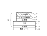
実施例1では、図1に示す構造の化粧料担持体1Aを製造するする方法及びその際に使用する積層体について説明する。実施例1で示す化粧料担持体1Aは、台材上に粘着層を介して化粧料担持層が形成されており、この化粧料担持層の上に化粧料層を有している。この化粧料層部分が台材よりも内側となるように小さく形成されているという構造的な特徴を有している。以下では、化粧料担持体1Aの構成を説明した後に、その製造方法を説明する。
In Example 1, a method for producing a
図1で、台材2はシート状の平坦な基材である。この台材2は後述する粘着層を介して化粧料担持層6を保持できる一定の剛性を備えたシート状の素材であればよく、特に限定されるものではない。例えば紙類、フィルム類、合成紙類、或いはこれらの積層シートを適宜に選択して採用できる。環境保護の観点から使用後に廃棄処理を行い易い紙類を使用することが好ましい。この台材2上には粘着層3が形成されている。
In FIG. 1, the
粘着層3の上部には剥離シート4が設けられている。この剥離シート4の上面にはさらに粘着層5が形成されている。剥離シート4は、粘着層(第1の粘着層)3よりも上側の粘着層5(第2の粘着層)と剥離し易くしておくことが重要である。すなわち、粘着層3と剥離シート4との粘着力が、粘着層5と剥離シート4との粘着力よりも大きくなるように設定しておく。例えば、剥離シート4の上面側にだけシリコーンなどの剥離剤を塗布するようにする。なお、このように粘着層の間に剥離シートを介した構造としている点については後述の説明で明らかとする。
A
剥離シート4上には、粘着層5を介して化粧料担持層6及び化粧料層10が設けられている。剥離シート4より上に設けられている粘着層5、化粧料担持層6及び化粧料層10は、エッジ(外縁)が台材2より内側に形成されている。図2(A)は、化粧料担持体1Aの外観を示した平面図である。この図により確認できるように化粧料担持体1Aの化粧料層10はエッジが所定幅だけ内側に形成されている。図2(B)は化粧料担持体1Aの断面を示しており、この図で示すように化粧料担持体1Aは積層体50Aから外側部分(不用部分)を除くことによって形成される。その際に、前述したように積層体50Aの上面に化粧料60を塗布しておくことで図1に示した上面に化粧料層10を備える化粧料担持体1Aを得ることができる。
On the
実際に化粧料担持体1Aを製造する場合には、図2(C)で示すように化粧料担持体1Aを複数(例えば100個)切出すことができる大判の積層体50Aを準備する。そして、図2(B)、(C)で示すように化粧料担持体1Aを切出すため上下から切込み51及び切込み52を予め形成しておく。図2(C)の積層体50Aの表面に化粧料60を塗布してから不用な枠部分Aを上方に取り除くと、図1に示した上面に化粧料層10を有する化粧料担持体1Aを得ることができる。なお、このようにして得られる化粧料担持体1Aの化粧料層10の外周面(エッジの外側面)は、後述するように、これよりも下側の化粧料担持層6と共に外側の不用部分を上方へ向けて剥離することにより形成される。よって、この外周面は、ほぼ垂直な剪断面となるので上方から見た輪郭(エッジの外形)が明瞭で、綺麗に形成されることになる。この化粧料担持体1Aは、図2(A)で示すように化粧料を保持しているチップ状の部材となる。よって、この化粧料担持体1Aを化粧コンパクトの筐体内の所定位置にセットすれば簡単に前述したレフィルのイメージの薄型コンパクトを製造できる。
When actually manufacturing the
そして、図1で示すように、台材2の下面側に粘着層21を設けておけば簡単にコンパクト内に固定することができる。さらに粘着層21を剥離シート22で覆っておけば、必要なとき剥離シート22を剥がしてコンパクトにセットできる。また、前述したように化粧料担持体1Aの化粧料層10は、台材2より外周が小さく形成されている。このように化粧料層10のエッジが台材2のエッジよりも内側に形成されていると、個々の化粧料担持体1Aをコンパクトにセットする等の組付け作業(ハンドリング)を行い易い。さらに、この化粧料担持体1Aを特に上方から見ると、化粧料層10の外側に見える台材2が金皿の縁のように見えるのでレフィルのイメージに近似した形態となる。
And as shown in FIG. 1, if the
図3及び図4で示す(A)〜(I)を参照して、化粧料担持体1Aの好ましい製造方法を詳細に説明する。図3の(A)で示すように、台材2上に下から順に粘着層3(第1の粘着層)、剥離シート4、粘着層5(第2の粘着層)及び化粧料担持層6を形成した積層体50Aを準備する。この積層体50Aは化粧料担持体1Aを複数(例えば10×10個)切出すことができる大きさの大判の部材として形成される(図2(C)参照)。前述したように台材2には紙類、フィルム類、合成紙類、或いはこれらの積層シートを適宜に選択して採用できるが。ここでは坪量250g/m2程度の厚紙が使用されている。粘着層3はアクリル系粘着剤、ゴム系粘着剤、シリコーン系粘着剤、エマルジョン系粘着剤などが使用可能であり、公知の塗工方法により台材2上に塗布される。
With reference to (A)-(I) shown in FIG.3 and FIG.4, the preferable manufacturing method of
剥離シート4は、例えば基材をクラフト紙、グラシン紙等とし両面をポリエチレンでラミネートしたり、樹脂等で処理した紙ベース、PETフィルム、OPPフィルム等のフィルムベースを用いることができる。そして、前述したように剥離シート4の上面には、剥離剤が塗布されている。剥離剤としては例えばシリコーン系、非シリコーン系並びに溶剤系、非溶剤系等を適宜に選択して使用することができる。この剥離シート4の上面はさらに粘着層5が設けられている。この粘着層5は、粘着層3と同様に形成すればよい。
As the
粘着層5の上には化粧料担持層6が形成される。この化粧料担持層6により化粧料層が担持される。先の背景技術において指摘したように、化粧料担持層6は複数回分の化粧料を保持できる素材で形成することが好ましい。例えばJIS B0651に規定の触針式表面粗さ測定器で測定し、JIS B0601に記載の方法に準じて表した中心線平均粗さ3.5〜10μmの表面粗さを有するシート材を用いて、化粧料担持層6を形成すると上記要求を満たすことができる。なお、上記表面粗さはより好ましくは3.5〜9.0μmであり、さらに好ましくは3.5〜8.0μmである。中心線平均粗さが3.5μmより小さくなると化粧料層の投錨効果が小さくなって密着性が低下して使用時に化粧料の脱落が生じ易くなり、製造工程でも脱落して製造が困難となる。また、中心線平均粗さが10μmを超えると化粧料の掻き取り残りが目立ちユーザの印象を損なう虞が生じて好ましくない。中心線平均粗さ3.5μmの表面粗さとは、市販マットコート紙に比べてはるかに粗く、粗仕上げしたラフ肌仕上げ書籍用紙に匹敵する表面粗さのレベルである。
A
化粧料担持層6は、化粧料を印刷などによって表面に固定できれば、特に限定されないが、上記表面粗さを有する単独フィルムや、フィルムと紙との積層物を採用できる。フィルム単独の材料として、例えばフィルム形成時にエンボス表面を有する冷却ロールで型付けされて製造されるポリカーボネートフィルムを好適に使用できる。また、ポリエステルフィルム(PET)も耐油性、耐熱性が高い材料である点で好ましい。ポリエステルフィルムを用いる場合には、表面加工を施して上記表面粗さを有する表面を形成して化粧料の保持性を高めることができる。
The cosmetic
図3の(B)では、台材2の下面側から剥離シート4まで切込み51を入れている。切込み51は粘着層5まで入れてもよい。この切込み51は、大判の積層体50Aから1個分の化粧料担持体1Aを切出す領域を規定するものである。すなわち、この切込み51は化粧料担持体の外形を規定するものであり、積層体50Aから切出す化粧料担持体1Aの個数分(例えば100個)が積層体50Aに形成される(図2(C)参照)。このように切込み51を形成しておくと、化粧料層10にダメージを与えることなく最後に不用部分を簡単に取除くことができる。なお、図3(A)では積層体50全体を示しているが、(B)以後の図では1個分の化粧料担持体1Aの周部を示している。
In FIG. 3B, a
図3(C)及び(D)で示すように、台材2の裏面(下面)側に粘着層21、剥離シート22を設ける裏面粘着加工が施される。このように粘着層21を設けておくと不用部分を取除いて独立した複数の化粧料担持体1Aを形成したときに、これらを粘着層21上に保持できる。また、粘着層21上に(図では下に)剥離シート22を設けることで、積層体50Aをある場所から他の場所に移送する際などに、粘着層21が他に付着することに配慮することなく作業性を行うことができる。さらに、化粧料担持体1Aをコンパクト等にセットするため剥離シート22から剥がせば、この粘着層21を利用してコンパクト等に固定できる。
As shown in FIGS. 3C and 3D, the back surface adhesive processing is performed in which the
上記のように粘着層21及び剥離シート22は、製造時における作業性を上げるために添付されるものであるから省略できる。すなわち、台材2の下側に上記粘着層21及び剥離シート22を設けない積層体を用いた場合でも上記と同様に化粧料担持体1Aを製造できる。この場合には、台材2の下面を吸引する機能を備えたテーブル等に支持しながら上記と同様の加工を行えばよい。そして、コンパクト側に粘着層を設けて、化粧料担持体1Aを固定すればよい。
As described above, the pressure-
図3の(E)で示す工程では、上面側から化粧料担持層6に切込み52を入れる。この切込みは粘着層5まで入れてもよい。切込み52により台材2上に設ける化粧料層10の大きさ(化粧料を担持させる領域)が規定される。前述したように、化粧料担持体1Aは台材2より化粧料層10を小さいという構造的な特徴がある。よって、上記切込み51に囲まれた領域内に切込み52が形成される(図2(B)及び(C)参照)。なお、特許請求の範囲の記載との関係では、切込み52が第1の切込みに対応し、切込み51が第2の切込みと対応する。図3(E)で示している状態の積層体50Aは、上下から上記切込み51、52が形成されている特徴的な構造となる。切込み51を予め形成しておくことで、最後に個々の化粧料担持体1Aに切出すときに化粧料層を壊すことなく簡単に個別化することができる。また、切込み52を形成しておくことでエッジが綺麗な化粧料層10を形成できる。よって、レフィルのイメージを形成するのに最適な化粧料層10を形成できる。
In the step shown in FIG. 3E, a
次に、図4(F)で示すように化粧料担持層6上に化粧料60を塗工する。化粧料としてはファンデーション、アイシャドウ、口紅等の固形化粧料を塗布できる。化粧料をファンデーションとする場合の一例を説明すると、溶剤としてイソプロピルアルコールを用いて適宜の濃度に調整したスラリー(塗液)を準備する。このスラリーをスクリーン印刷により化粧料担持層6上に塗布する。ここでは図示するように切込み52を形成した領域よりも化粧料60が広めに塗布される。例えば付着量が180g/m2程度となるように、厚膜スクリーン印刷を用いて3回重ね印刷すると複数回分の化粧料を付着させることができる。
Next, as shown in FIG. 4F, a cosmetic 60 is applied on the cosmetic-supporting
次に、図4(G)で示すように外側の上側部分A(図2(C)参照)を上方に剥離する。この工程では、例えば吸引機能を有するテーブル上に固定して、不用部分Aを上方に引き剥がす。この剥離処理は、化粧料担持層6上の化粧料60が適度に湿っている状態で実行する。例えば、化粧料60は固形分を60%として化粧料担持層6上に塗布する。この固形分が90%を超える前に図4(G)の剥離処理を行うのが望ましい。この剥離処理により剥離シート4より上側の部分(粘着層5、化粧料担持層6及び化粧料60)が剥離されるが、切込み52によって囲まれた内側は残り、図4(H)で示す化粧料担持層6上に化粧料層10を備えた構造体が得られる。このように形成される図4(H)の構造体は、粘着層5より上方部分の外周面は化粧料層10の面に対してほぼ垂直な剪断面となり、化粧料層10のエッジがきれいに形成されることになる。最後に、図4(H)の構造体の外側に残る不用な枠部分Bを剥離すると図4(I)示すように剥離シート22上に保持された化粧料担持体1Aを得ることができる。よって、化粧料担持体1Aを剥離シート22から剥がしながら使用できる。
Next, as shown in FIG. 4G, the outer upper portion A (see FIG. 2C) is peeled upward. In this step, for example, it is fixed on a table having a suction function, and the unnecessary portion A is peeled upward. This peeling process is performed in a state where the cosmetic 60 on the
なお、上記の説明から理解されるように、台材2上に設けた剥離シート4は、図4(G)で示す状態からA部分をスムーズに剥離して図4(H)で示す構造を得るために配置されている。台材2の上面にシリコーン等の剥離剤をコートして粘着層5を剥離できるように形成した場合には、図3及び図4で示しているのと同様の工程によって構造を簡素化した変形タイプの化粧料担持体1Bを製造することができる。このときに用いる積層体50Bは、図3(A)で示す積層体50Aから粘着層3及び剥離シート4を除いた構造であるので図示を省略するが、この積層体50Bによって製造される化粧料担持体1Bの構造を図5に示す。この台材2は上面に剥離コート層2aを備えている。
As can be understood from the above description, the
以上で説明した化粧料担持体1A及び1Bは、最上面に位置する化粧料層10はエッジが明確な形状となる。そして、これよりも下側で段状に残る剥離シート4(化粧料担持体1Bの場合は台材2)の外周部が化粧料層10の外周を囲むように形成されている。よって、実際のコンパクトで化粧料の外側に金皿の外周(縁取り)が見える形態(前述したレフィルのイメージの形態)に近い形状を再現できる。このような化粧料担持体1A(或いは1B)を図6で示す化粧コンパクト100の筐体101内の所定位置102に固定すれば薄型で、携帯性に富み、見栄えの良いコンパクトとして提供できる。このようなコンパクト100を試供品とすれば、従来の印刷タイプの試供品よりも製品のイメージを高めてユーザの購買を促進できる。なお、コンパクト100の蓋103の裏面103aにも上記化粧料担持体1A(或いは1B)を取付けてもよい。この場合には化粧回数をさらに増加させたより好ましい化粧コンパクトになる。なお、コンパクトにパフを同封しておけば、更に製品のイメージに近づけることができるので好ましい形態の一つとなる。また、このコンパクト100は、従来のミニチュア(金皿充填タイプ)よりも広い印刷面を確保でき、しかも低コストにて製造できる。
In the
さらに、上記化粧料担持体1A、1Bの各部は大部分を紙で形成することができるので、コンパクト100の筐体も紙で形成した場合には、使用後には燃えるゴミとして処分できため環境適用性も兼ね備えた試供品としてユーザに提供できる。
Furthermore, since most parts of the
上記実施例1ではレフィルに近い形態を再現できる化粧料担持体1A及び1Bの構造と製造方法について説明した。しかし、先に大略で説明したように本発明によると化粧料層10のエッジをきれいに形成できるという本質的な特徴がある。このようにエッジが明瞭であれば金皿の外周に似せた外周部分(縁取り)のない形態であっても、同様に製品のイメージを高めることができる。実施例2は化粧料層10がきれいなエッジを有し、実施例1よりもシンプルな構造の化粧料担持体1Cについて説明する。
In Example 1 described above, the structure and the manufacturing method of the
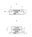
図7は、実施例2に係る化粧料担持体1Cについて示した図である。図7(A)は化粧料担持体1Cの形成に用いる積層体50C、図7(B)は化粧料担持体1Cを示している。なお、重複する説明を避けるため実施例1で示した化粧料担持体1Aと実質的に同じ部位には、同一の符号を付している。
FIG. 7 is a diagram illustrating the cosmetic carrier 1C according to the second embodiment. FIG. 7A shows a
この積層体50Cは台材2上に粘着層5を介して化粧料担持層6を備えている。化粧料担持層6から台材2まで切込み53が形成されている。切込み53は粘着層21まで入れてもよい。ここでの切込み53により、化粧料担持体1Cを切出す領域及び台材2上に設ける化粧料層10の大きさが規定される。すなわち、この切込み53は、実施例1で示した2つの切込み51、52を兼ねている。
The laminated body 50 </ b> C includes a cosmetic
図7(A)で示している積層体50Cで切込み53より外側の部分を除去すると、図7(B)で示す化粧料担持体1Cを得ることができる。この化粧料担持体1Cは、実施例1の化粧料担持体1Aのように縁取り部分はないが化粧料層10のエッジはきれいに形成される。よって、化粧料担持体1Cを試供品の化粧コンパクトにセットした場合にもレフィルイメージとなるので、製品のイメージを高めてユーザの購買を促進できる。図7に示す化粧料担持体1Cは、実施例1の場合と比較して、用いる積層体50Cがシンプルであり、加工数が減少するので製造コストを低減できる。
When a portion outside the
前述した実施例による化粧料担持体1A〜1Cは全体を支持する台材2を備えるので形状が安定である。しかし、台材2を除くことにより、よりシンプルな化粧料担持体を製造できる。実施例3は、さらにシンプルな構造の化粧料担持体1Dについて説明する。
Since
図8は、実施例3に係る化粧料担持体1Dについて示した図である。図8(A)は化粧料担持体1Cの形成に用いる積層体50D、図8(B)は化粧料担持体1Dを示している。この図でも、重複する説明を避けるため実施例1で示した化粧料担持体1Aと実質的に同じ部位には、同一の符号を付している。
FIG. 8 is a diagram illustrating the
この積層体50Dは台材を有しておらず、剥離シート22上に粘着層21を介して化粧料担持層6が設けられている。化粧料担持層6には切込み54が形成されている。切込み54は粘着層21まで入れてもよい。
This laminated body 50 </ b> D does not have a base material, and the cosmetic
図8(A)で示している積層体50Dで切込み54より外側の部分を剥離すると、図8(B)で示す化粧料担持体1Dを得ることができる。なお、この剥離処理は吸引機能を有するテーブル上に剥離シート22を吸引しながら行えばよい。この化粧料担持体1Dも実施例1の化粧料担持体1Aのように縁取り部分はないが化粧料層10のエッジはきれいに形成される。よって、化粧料担持体1Dを試供品の化粧コンパクトにセットした場合にもレフィルイメージとなるので、製品のイメージを高めてユーザの購買を促進できる。図8に示している化粧料担持体1Dは用いる積層体50Dが極めてシンプルであり、使用する素材や加工数が大幅に減少するので製造コストを大幅に低減できる。
When the portion outside the
以上本発明の好ましい一実施形態について詳述したが、本発明は係る特定の実施形態に限定されるものではなく、特許請求の範囲に記載された本発明の要旨の範囲内において、種々の変形・変更が可能である。 The preferred embodiment of the present invention has been described in detail above, but the present invention is not limited to the specific embodiment, and various modifications can be made within the scope of the gist of the present invention described in the claims.・ Change is possible.
1A〜1D 化粧料担持体
2 台材
3 粘着層
4 剥離シート
5 粘着層
6 化粧料担持層
10 化粧料層
50A、50C,50D 積層体
51 切込み(第2の切込み)
52 切込み(第1の切込み)
53 切込み
54 切込み
60 化粧料
100 コンパクト
DESCRIPTION OF
52 cutting (first cutting)
53 cutting 54 cutting 60
Claims (13)
前記化粧料担持層に、化粧料を担持させる領域を規定する切込みが形成されていることを特徴とする積層体。 A laminate for producing a cosmetic carrier, wherein a cosmetic carrier layer is provided on the release sheet via an adhesive layer,
A cutout for defining a region for carrying a cosmetic is formed in the cosmetic carrying layer.
前記化粧料担持層から前記台材まで、化粧料を担持させる領域を規定する切込みが形成されていることを特徴とする積層体。 A laminate for producing a cosmetic carrier, wherein a base material is provided on a release sheet via a first adhesive layer, and a cosmetic carrier layer is provided on the base material via a second adhesive layer. ,
The laminate is characterized in that a cut defining a region for supporting cosmetic is formed from the cosmetic supporting layer to the base material.
前記化粧料担持層には、化粧料を担持させる領域を規定する第1の切込みが形成され、
前記台材には、前記領域よりも大きい化粧料担持体の外形を規定する第2の切込みが形成されていることを特徴とする積層体。 A laminate for producing a cosmetic carrier, in which a cosmetic carrier layer is provided on a sheet-like base material via an adhesive layer,
The cosmetic carrier layer is formed with a first notch that defines a region on which the cosmetic material is carried,
The base material is formed with a second notch that defines an outer shape of the cosmetic carrier larger than the region.
前記第2の切込みが前記台材から前記剥離シートまで形成され、
前記第1の粘着層と前記剥離シートとの粘着力が、前記第2の粘着層と前記剥離シートとの粘着力より大きくなるように設定されていることを特徴とする請求項3に記載の積層体。 The adhesive layer is disposed between a first adhesive layer disposed between the base material and the release sheet, the cosmetic material carrying layer, and the release sheet with a release sheet interposed therebetween. A second adhesive layer,
The second cut is formed from the base material to the release sheet;
The adhesive force between the first adhesive layer and the release sheet is set to be larger than the adhesive force between the second adhesive layer and the release sheet. Laminated body.
前記化粧料担持層上に化粧料を塗布する第2の工程と、
前記切込みより外側の不用部分を除く第3の工程とを含むことを特徴とする化粧料担持体の製造方法。 A first step of producing the laminate according to any one of claims 1 to 7;
A second step of applying a cosmetic on the cosmetic carrier layer;
And a third step of removing an unnecessary portion outside the cut, and a method for producing a cosmetic carrier.
前記化粧料層及び前記化粧料担持層の外周面が、前記化粧料層の面に対して垂直な剪断面となっていることを特徴とする化粧料担持体。 A cosmetic carrier having a cosmetic layer carried on the cosmetic carrier layer,
The cosmetic carrier, wherein outer peripheral surfaces of the cosmetic layer and the cosmetic carrier layer are shear planes perpendicular to the surface of the cosmetic layer.
前記化粧料層及び前記化粧料担持層の外周面が、前記化粧料層の面に対して垂直な剪断面となっていることを特徴とする化粧料担持体。 A cosmetic carrier on which a cosmetic carrier layer is provided on a base material via an adhesive layer, and the cosmetic layer is carried on the cosmetic carrier layer,
The cosmetic carrier, wherein outer peripheral surfaces of the cosmetic layer and the cosmetic carrier layer are shear planes perpendicular to the surface of the cosmetic layer.
前記化粧料層及び前記化粧料担持層が前記台材よりも小さく形成され、該前記化粧料層及び前記化粧料担持層の外周面が、前記化粧料層の面に対して垂直な剪断面となっていることを特徴とする化粧料担持体。 A cosmetic carrier on which a cosmetic carrier layer is provided on a base material via an adhesive layer, and the cosmetic layer is carried on the cosmetic carrier layer,
The cosmetic layer and the cosmetic support layer are formed smaller than the base material, and the outer peripheral surfaces of the cosmetic layer and the cosmetic support layer are shear planes perpendicular to the surface of the cosmetic layer. A cosmetic carrier characterized by the above.
A cosmetic compact comprising the cosmetic carrier according to any one of claims 10 to 12 in a housing.
Priority Applications (1)
| Application Number | Priority Date | Filing Date | Title |
|---|---|---|---|
| JP2005013978A JP4753587B2 (en) | 2005-01-21 | 2005-01-21 | Method for producing cosmetic carrier and cosmetic compact provided with cosmetic carrier |
Applications Claiming Priority (1)
| Application Number | Priority Date | Filing Date | Title |
|---|---|---|---|
| JP2005013978A JP4753587B2 (en) | 2005-01-21 | 2005-01-21 | Method for producing cosmetic carrier and cosmetic compact provided with cosmetic carrier |
Publications (2)
| Publication Number | Publication Date |
|---|---|
| JP2006198217A true JP2006198217A (en) | 2006-08-03 |
| JP4753587B2 JP4753587B2 (en) | 2011-08-24 |
Family
ID=36956713
Family Applications (1)
| Application Number | Title | Priority Date | Filing Date |
|---|---|---|---|
| JP2005013978A Active JP4753587B2 (en) | 2005-01-21 | 2005-01-21 | Method for producing cosmetic carrier and cosmetic compact provided with cosmetic carrier |
Country Status (1)
| Country | Link |
|---|---|
| JP (1) | JP4753587B2 (en) |
Cited By (5)
| Publication number | Priority date | Publication date | Assignee | Title |
|---|---|---|---|---|
| JP2013000276A (en) * | 2011-06-15 | 2013-01-07 | Tokiwa Corp | Powder cosmetic material sample for display |
| WO2013133344A1 (en) | 2012-03-06 | 2013-09-12 | 株式会社タイキ | Cosmetics applicator |
| JP2013236794A (en) * | 2012-05-16 | 2013-11-28 | Nippon Paper Papylia Co Ltd | Multicolor cosmetic product and method for manufacturing the same |
| JP2015024064A (en) * | 2013-07-29 | 2015-02-05 | 日本製紙パピリア株式会社 | Multicolored cosmetic, and production method thereof |
| KR20200058938A (en) * | 2018-11-20 | 2020-05-28 | 코스맥스 주식회사 | Inner Container for Powder Cosmetic |
Families Citing this family (1)
| Publication number | Priority date | Publication date | Assignee | Title |
|---|---|---|---|---|
| KR102620499B1 (en) * | 2023-07-26 | 2024-01-03 | 한국콜마주식회사 | Pad lamination |
Citations (3)
| Publication number | Priority date | Publication date | Assignee | Title |
|---|---|---|---|---|
| JPH02129114A (en) * | 1988-11-08 | 1990-05-17 | Kanebo Ltd | Thin filmy powder solid cosmetic |
| JPH08308633A (en) * | 1995-01-20 | 1996-11-26 | Color Prelude Inc | Cosmetic sampler with integral applicator |
| JP2005013335A (en) * | 2003-06-24 | 2005-01-20 | Toppan Printing Co Ltd | Container for free sample of cosmetic |
-
2005
- 2005-01-21 JP JP2005013978A patent/JP4753587B2/en active Active
Patent Citations (3)
| Publication number | Priority date | Publication date | Assignee | Title |
|---|---|---|---|---|
| JPH02129114A (en) * | 1988-11-08 | 1990-05-17 | Kanebo Ltd | Thin filmy powder solid cosmetic |
| JPH08308633A (en) * | 1995-01-20 | 1996-11-26 | Color Prelude Inc | Cosmetic sampler with integral applicator |
| JP2005013335A (en) * | 2003-06-24 | 2005-01-20 | Toppan Printing Co Ltd | Container for free sample of cosmetic |
Cited By (9)
| Publication number | Priority date | Publication date | Assignee | Title |
|---|---|---|---|---|
| JP2013000276A (en) * | 2011-06-15 | 2013-01-07 | Tokiwa Corp | Powder cosmetic material sample for display |
| WO2013133344A1 (en) | 2012-03-06 | 2013-09-12 | 株式会社タイキ | Cosmetics applicator |
| CN104349695A (en) * | 2012-03-06 | 2015-02-11 | 株式会社黛怡茜 | Cosmetics applicator |
| US9498043B2 (en) | 2012-03-06 | 2016-11-22 | Taiki Corp., Ltd. | Cosmetics applicator |
| CN104349695B (en) * | 2012-03-06 | 2017-05-03 | 株式会社黛怡茜 | Cosmetics applicator |
| JP2013236794A (en) * | 2012-05-16 | 2013-11-28 | Nippon Paper Papylia Co Ltd | Multicolor cosmetic product and method for manufacturing the same |
| JP2015024064A (en) * | 2013-07-29 | 2015-02-05 | 日本製紙パピリア株式会社 | Multicolored cosmetic, and production method thereof |
| KR20200058938A (en) * | 2018-11-20 | 2020-05-28 | 코스맥스 주식회사 | Inner Container for Powder Cosmetic |
| KR102120043B1 (en) * | 2018-11-20 | 2020-06-09 | 코스맥스 주식회사 | Inner Container for Powder Cosmetic |
Also Published As
| Publication number | Publication date |
|---|---|
| JP4753587B2 (en) | 2011-08-24 |
Similar Documents
| Publication | Publication Date | Title |
|---|---|---|
| US6153279A (en) | Label with flexible magnet and web printing process | |
| JP4753587B2 (en) | Method for producing cosmetic carrier and cosmetic compact provided with cosmetic carrier | |
| US20020089171A1 (en) | Business card system | |
| JP4436636B2 (en) | Multilayer label, receptacle provided with multilayer label, and method of manufacturing multilayer label | |
| JP2004070272A (en) | Laminated label and its manufacturing method | |
| JPH06102827A (en) | Multilayered label | |
| JP5614970B2 (en) | Solid cosmetics | |
| WO2001005268A1 (en) | Cosmetic material sheet and method for manufacture of the sheet and apparatus for use in the manufacture | |
| JP3120639U (en) | Delivery slip | |
| JP4920706B2 (en) | Slip sheet | |
| JP3059175U (en) | Double-sided adhesive body with adhesive body formed by printing | |
| JP4417425B1 (en) | Slip sheet | |
| CN212181797U (en) | Label paper | |
| JPS6324107Y2 (en) | ||
| JP3185240U (en) | Seal having a removable layer of adhesive | |
| CN220121381U (en) | Waterproof self-adhesive label | |
| JP3278421B2 (en) | Cosmetic sheet manufacturing method and apparatus used therefor | |
| JP2010173669A (en) | Container with label | |
| JP2824968B2 (en) | Lottery postcard and method of manufacturing the same | |
| JPH02245390A (en) | Postal card and production thereof | |
| JP3067032U (en) | Stencil transfer seal set | |
| JP2008158262A (en) | Label | |
| JPH0111493Y2 (en) | ||
| CN111402707A (en) | Label paper and manufacturing method thereof | |
| EP0989935B1 (en) | Laminated structure |
Legal Events
| Date | Code | Title | Description |
|---|---|---|---|
| RD04 | Notification of resignation of power of attorney |
Free format text: JAPANESE INTERMEDIATE CODE: A7424 Effective date: 20070331 |
|
| RD02 | Notification of acceptance of power of attorney |
Free format text: JAPANESE INTERMEDIATE CODE: A7422 Effective date: 20070413 |
|
| RD04 | Notification of resignation of power of attorney |
Free format text: JAPANESE INTERMEDIATE CODE: A7424 Effective date: 20070601 |
|
| A621 | Written request for application examination |
Free format text: JAPANESE INTERMEDIATE CODE: A621 Effective date: 20070717 |
|
| A977 | Report on retrieval |
Free format text: JAPANESE INTERMEDIATE CODE: A971007 Effective date: 20101028 |
|
| A131 | Notification of reasons for refusal |
Free format text: JAPANESE INTERMEDIATE CODE: A131 Effective date: 20101124 |
|
| A521 | Written amendment |
Free format text: JAPANESE INTERMEDIATE CODE: A523 Effective date: 20110119 |
|
| TRDD | Decision of grant or rejection written | ||
| A01 | Written decision to grant a patent or to grant a registration (utility model) |
Free format text: JAPANESE INTERMEDIATE CODE: A01 Effective date: 20110518 |
|
| A01 | Written decision to grant a patent or to grant a registration (utility model) |
Free format text: JAPANESE INTERMEDIATE CODE: A01 |
|
| A61 | First payment of annual fees (during grant procedure) |
Free format text: JAPANESE INTERMEDIATE CODE: A61 Effective date: 20110524 |
|
| FPAY | Renewal fee payment (event date is renewal date of database) |
Free format text: PAYMENT UNTIL: 20140603 Year of fee payment: 3 |
|
| R150 | Certificate of patent or registration of utility model |
Ref document number: 4753587 Country of ref document: JP Free format text: JAPANESE INTERMEDIATE CODE: R150 Free format text: JAPANESE INTERMEDIATE CODE: R150 |
|
| R250 | Receipt of annual fees |
Free format text: JAPANESE INTERMEDIATE CODE: R250 |