JP2006190078A - Pattern matching device - Google Patents
Pattern matching device Download PDFInfo
- Publication number
- JP2006190078A JP2006190078A JP2005001407A JP2005001407A JP2006190078A JP 2006190078 A JP2006190078 A JP 2006190078A JP 2005001407 A JP2005001407 A JP 2005001407A JP 2005001407 A JP2005001407 A JP 2005001407A JP 2006190078 A JP2006190078 A JP 2006190078A
- Authority
- JP
- Japan
- Prior art keywords
- image
- pattern
- partial image
- template
- partial
- Prior art date
- Legal status (The legal status is an assumption and is not a legal conclusion. Google has not performed a legal analysis and makes no representation as to the accuracy of the status listed.)
- Granted
Links
Images


Abstract
Description
この発明は画像処理のテンプレートマッチングによって物体上のパターン位置を検出するパターンマッチング装置に関する。 The present invention relates to a pattern matching apparatus that detects a pattern position on an object by template matching of image processing.
半導体素子等の製造工程では、様々な材料膜の回路パターンを精度良く重ね合せるため、露光工程の前に、半導体ウエハ等の基板のアライメントを行い、現像工程の後、加工工程の前に、基板上のレジストパターンの重ね合せ検査を行っている。 In the manufacturing process of semiconductor elements, etc., in order to superimpose circuit patterns of various material films with high accuracy, the substrate such as a semiconductor wafer is aligned before the exposure process, and after the development process, before the processing process, the substrate The upper resist pattern is overlaid.
基板のアライメントや基板上のレジストパターンの重ね合わせにはパターンマッチング装置が用いられる。 A pattern matching device is used for alignment of the substrate and overlaying of the resist pattern on the substrate.
従来、パターンマッチング装置として、例えばCCD等の撮像素子を用いて基板上のアライメントマーク(所定のパターン)の画像を取り込み、この画像とテンプレートとして登録したパターンとの正規化相関によりパターンマッチングを行い、アライメントマークの位置を検出するものが知られている。
しかし、取り込まれた画像内に疑似パターンが存在したり、ノイズが重畳したりする場合には、疑似パターン等の位置が検出すべきパターンの位置として検出されてしまうことがある。 However, when a pseudo pattern exists in the captured image or noise is superimposed, the position of the pseudo pattern or the like may be detected as the position of the pattern to be detected.
この発明はこのような事情に鑑みてなされたもので、その課題は検出すべきパターンの位置を誤りなく検出することができるパターンマッチング装置を提供することである。 The present invention has been made in view of such circumstances, and an object thereof is to provide a pattern matching apparatus that can detect the position of a pattern to be detected without error.
前述の課題を解決するため請求項1記載の発明は、テンプレートとして線対称性を有するパターン画像と、検索対象画像から切り出された前記テンプレートと同一サイズの部分画像との相関値を算出する相関値算出手段と、前記部分画像を中心線に対して反転させた反転画像を作成し、この反転画像と前記部分画像との自己相関値を算出する自己相関値算出手段と、前記相関値算出手段で算出された相関値と前記自己相関値算出手段で算出された自己相関値とに基づいて前記テンプレートと前記部分画像との類似度を算出する類似度算出手段とを備えていることを特徴とする。
In order to solve the above-mentioned problem, the invention according to
請求項2記載の発明は、テンプレートとして点対称性を有するパターン画像と、検索対象画像から切り出された前記テンプレートと同一サイズの部分画像との相関値を算出する相関値算出手段と、前記部分画像を中心点周りに回転させたときの回転画像を作成し、この回転画像と前記部分画像との自己相関値を算出する自己相関値算出手段と、前記相関値算出手段で算出された相関値と前記自己相関値算出手段で算出された自己相関値とに基づいて前記テンプレートと前記部分画像との類似度を算出する類似度算出手段とを備えていることを特徴とする。
請求項3記載の発明は、請求項1又は2記載のパターンマッチング装置において、前記検索対象画像から切り出された複数の前記部分画像のうち、前記テンプレートに対して最も高い類似度を有する部分画像の位置を最適位置として検出する最適位置検出手段を備えていることを特徴とする。
According to a second aspect of the present invention, there is provided a correlation value calculating means for calculating a correlation value between a pattern image having point symmetry as a template and a partial image of the same size as the template cut out from the search target image, and the partial image An autocorrelation value calculating means for calculating an autocorrelation value between the rotated image and the partial image, and a correlation value calculated by the correlation value calculating means. The image processing apparatus includes: a similarity calculation unit that calculates a similarity between the template and the partial image based on the autocorrelation value calculated by the autocorrelation value calculation unit.
According to a third aspect of the present invention, in the pattern matching device according to the first or second aspect, the partial image having the highest similarity to the template among the plurality of partial images cut out from the search target image. An optimum position detecting means for detecting the position as the optimum position is provided.
この発明によれば、検出すべきパターンの位置を誤りなく検出することができる。 According to the present invention, the position of the pattern to be detected can be detected without error.
以下この発明の実施の形態を図面に基づいて説明する。 Embodiments of the present invention will be described below with reference to the drawings.
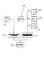
図1はこの発明の第1実施形態に係るパターンマッチング装置のブロック図である。 FIG. 1 is a block diagram of a pattern matching apparatus according to the first embodiment of the present invention.
このパターンマッチング装置はステージ11と光学系12とCCDカメラ13と画像処理部14と記憶部15とで構成されている。
This pattern matching apparatus includes a
ステージ11の上面には図示しない搬送系によって搬送されてきた基板10Aが載置される。基板10Aは真空吸着等によってステージ11の上面に保持される。ステージ11は水平面内で2次元方向へ移動可能である。ステージ11は検出対象であるパターンの位置検出の際に基板10Aの複数の領域を一定の順序で1つずつ視野(カメラ13の撮像視野)内に位置決めする。
On the upper surface of the
光学系12は基板10Aの所定の領域の光学像を形成する。
The
カメラ13は基板10Aの複数の領域を順次撮像し、取得した検索対象画像(各領域に対応する画像)2を画像処理部14へ出力する。
The
画像処理部14は画像入力部14Aと相関値算出部(相関値算出手段)14Bと自己相関値算出部(自己相関値算出手段)14Cと類似度算出部(類似度算出手段)14Dと最適位置検出部(最適位置検出手段)14Eとを備えている。
The
画像処理部14では画像入力部14Aに取り込まれた撮像信号がデジタル画像に変換され、この入力画像に対して相関値算出部14B、自己相関値算出部14C、類似度算出部14D及び最適位置検出部14Eによるパターンマッチング等の画像処理が行われる。
In the
記憶部15にはテンプレート1のパターン画像が予め記憶されている。例えばテスト基板上に作成されたパターンの画像が含まれたテンプレート用画像を画像処理部14に取り込み、その画像から特定部分の画像を切り出すことによってテンプレート1のパターン画像を作成することができる。
A pattern image of the
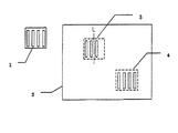
図2は線対称性を有するテンプレートの一例を示す図、図3は検索対象画像内の疑似パターンの位置と最適パターンの位置とを示す図である。 FIG. 2 is a diagram illustrating an example of a template having line symmetry, and FIG. 3 is a diagram illustrating a position of a pseudo pattern and a position of an optimum pattern in a search target image.
テンプレート1にはそれぞれの長さ及び幅が同じである4本のバーを等間隔に配置してなるパターンが形成されている。テンプレート1は中心線Lに関して対称である。
The
検索対象画像2内には、テンプレート1と同一のパターンの部分画像4とテンプレート1のパターンに類似する疑似パターンの部分画像3とがある。ここで、部分画像とは検索対象画像2から切り出された部分的な画像をいう。
The
部分画像3中には疑似パターンを構成する3本のバーが等間隔に配置されている。3本のバーの長さ及び幅はテンプレート1のパターンの長さ及び幅と同じである。
In the
なお、部分画像3及び部分画像4はテンプレート1と同一サイズである。
The
次に、検出すべきパターンの位置の検出方法を図1〜4を用いて説明する。 Next, a method for detecting the position of the pattern to be detected will be described with reference to FIGS.
図4はテンプレートと部分画像との類似度の検出方法を説明する図である。 FIG. 4 is a diagram for explaining a method of detecting the similarity between a template and a partial image.
上記パターンマッチング装置で実行される位置検出方法について説明する。 A position detection method executed by the pattern matching apparatus will be described.
まず、記憶部15からテンプレート1としてのパターン画像を読み出す。
First, the pattern image as the
次に、ステージ11を移動させる。カメラ13で基板10Aの所定の領域の光学像を撮像して検索対象画像2を取得し、撮像信号を画像処理部14へ出力する。
Next, the
次に、検索対象画像2から部分画像3を切り出す。
Next, the
そして、検索対象画像2から切り出された部分画像3とテンプレート1のパターン画像とを正規化相関によりパターンマッチングさせ、テンプレート1のパターン画像と部分画像3との相関値C1を算出し、その結果を記憶部15に記憶させる。
Then, the
次に、部分画像3を中心線Lに対して反転させて作成した反転画像5と部分画像3とを正規化相関によりパターンマッチングさせ、反転画像5と部分画像3との自己相関値C2を算出し、その結果を記憶部15に記憶させる。
Next, the inverted image 5 created by inverting the
その後、相関値C1と自己相関値C2とを足し合わせて、部分画像3のテンプレート1のパターン画像に対する類似度C3を算出し、その結果を記憶部15に記憶させる。
Thereafter, the correlation value C1 and the autocorrelation value C2 are added to calculate the similarity C3 of the
次に、検索対称画像2から部分画像4を切り出す。
Next, the
そして、検索対称画像2から切り出された部分画像4とテンプレート1のパターン画像とを正規化相関によりパターンマッチングさせ、テンプレート1のパターン画像と部分画像4との相関値C1をそれぞれ算出し、その結果を記憶部15に記憶させる。
Then, the
次に、部分画像4を中心線Lに対して反転させて作成した反転画像5と部分画像3とを正規化相関によりパターンマッチングさせ、反転画像5と部分画像4との自己相関値C2を算出し、その結果を記憶部15に記憶させる。
Next, the inverted image 5 created by inverting the
その後、相関値C1と自己相関値C2とを足し合わせて、部分画像4のテンプレート1のパターン画像に対する類似度C3を算出し、その結果を記憶部15に記憶させる。
Thereafter, the correlation value C1 and the autocorrelation value C2 are added to calculate the similarity C3 of the
次に、記憶部15から読み出された部分画像3の類似度C3と部分画像4の類似度C3とを比較し、高い類似度C3を有する方の部分画像4の位置を最適位置(検出すべきパターンの位置)として検出する。パターンマッチングの演算を相関法により行った場合、類似性が高い程、類似度C3は大きくなることから最適位置を検出できる。
Next, the similarity C3 of the
なお、上記位置検出方法によれば、テンプレート1と同一のパターンを有する部分画像4にノイズが重畳した場合においても、部分画像4はテンプレート1のパターン画像に対して最も高い類似度C3を有するので、部分画像4の位置を最適位置として検出することができる。
According to the position detection method, even when noise is superimposed on the
この実施形態によれば、検索対称画像2にノイズが重畳したり、疑似パターンが存在したりした場合であっても、ノイズや疑似パターンの影響を受けることなく、検出すべき線対称性を有するパターンの位置を誤りなく検出することができる。
According to this embodiment, even when noise is superimposed on the search
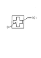
図5はこの発明の第2実施形態に係るパターンマッチング装置に使用される点対称性を有するテンプレートの一例を示す図、図6は検索対象画像内の疑似パターンの位置と最適パターンの位置とを示す図であり、第1実施形態と共通する部分には同一符合を付してその説明を省略する。 FIG. 5 is a diagram showing an example of a template having point symmetry used in the pattern matching apparatus according to the second embodiment of the present invention. FIG. 6 shows the positions of the pseudo pattern and the optimum pattern in the search target image. In the figure, the same reference numerals are given to the portions common to the first embodiment, and the description thereof is omitted.
テンプレート101には十字形パターンが形成されている。パターンは中心点Oに関して対称である。
A cross pattern is formed on the
検索対象画像2内にはテンプレート101と同一のパターンの部分画像104とテンプレート101のパターンに類似する疑似パターンの部分画像103とがある。
The
部分画像103中にはほぼT字形の疑似パターンが形成されている。
In the
なお、部分画像103及び部分画像104はテンプレート101と同一サイズである。
Note that the
次に、検出すべきパターンの位置検出方法を図1,6及び7を用いて説明する。 Next, a method for detecting the position of the pattern to be detected will be described with reference to FIGS.
図7はテンプレートと部分画像との類似度の検出方法を説明するブロック図である。 FIG. 7 is a block diagram illustrating a method for detecting the similarity between a template and a partial image.
上記パターンマッチング装置で実行される位置検出方法について説明する。 A position detection method executed by the pattern matching apparatus will be described.
まず、記憶部15からテンプレート101としてのパターン画像を読み出す。
First, a pattern image as the
次に、ステージ11を移動させる。カメラ13で基板10Aの所定の領域の光学像を撮像して検索対象画像2を取得し、撮像信号を画像処理部14へ出力する。
Next, the
次に、検索対象画像2から部分画像103を切り出す。
Next, the
そして、検索対象画像2から切り出された部分画像103とテンプレート101のパターン画像とを正規化相関によりパターンマッチングさせ、テンプレート101のパターン画像と部分画像103との相関値C1を算出し、その結果を記憶部15に記憶させる。
Then, the
次に、部分画像103を中心点O周りに90°反時計回りに回転させて作成した回転画像106と部分画像103とを正規化相関によりパターンマッチングさせ、回転画像106と部分画像103との自己相関値C21を算出し、その結果を記憶部15に記憶させる。
Next, the rotated
その後、部分画像103を更に中心点O周りに更に90°反時計回りに回転させて作成した回転画像107と部分画像103とを正規化相関によりパターンマッチングさせ、回転画像107と部分画像103との自己相関値C22を算出し、その結果を記憶部15に記憶させる。
Thereafter, the
次に、部分画像103を更に中心点O周りに更に90°回転させて作成した回転画像108と部分画像103とを正規化相関によりパターンマッチングさせ、回転画像108と部分画像103との自己相関値C23を算出し、その結果を記憶部15に記憶させる。
Next, the rotated
その後、自己相関値C21、自己相関値C22及び自己相関値C23を順次足し合わせて、部分画像103と回転画像106,107,108との自己相関値C2を算出し、その結果を記憶部15に記憶させる。
Thereafter, the autocorrelation value C21, the autocorrelation value C22, and the autocorrelation value C23 are sequentially added to calculate the autocorrelation value C2 between the
次に、相関値C1と自己相関値C2とを足し合わせて、部分画像103のテンプレート1のパターン画像に対する類似度C3を算出し、その結果を記憶部15に記憶させる。
Next, the correlation value C1 and the autocorrelation value C2 are added together to calculate the similarity C3 of the
その後、検索対称画像2から部分画像104を切り出す。
Thereafter, the
そして、検索対称画像2から切り出された部分画像104とテンプレート101のパターン画像とを正規化相関によりパターンマッチングさせ、テンプレート101のパターン画像と部分画像104との相関値C1をそれぞれ算出し、その結果を記憶部15に記憶させる。
Then, the
次に、部分画像104を中心点O周りに90°反時計方向に回転させて作成した回転画像106と部分画像104とを正規化相関によりパターンマッチングさせ、回転画像106と部分画像104との自己相関値C21を算出し、その結果を記憶部15に記憶させる。
Next, the rotated
その後、部分画像104を更に中心点O周りに更に90°回転させて作成した回転画像107と部分画像104とを正規化相関によりパターンマッチングさせ、回転画像107と部分画像103との自己相関値C22を算出し、その結果を記憶部15に記憶させる。
Thereafter, the
次に、部分画像104を更に中心点O周りに更に90°回転させて作成した回転画像108と部分画像104とを正規化相関によりパターンマッチングさせ、回転画像108と部分画像104との自己相関値C23を算出し、その結果を記憶部15に記憶させる。
Next, the rotated
その後、自己相関値C21と自己相関値C22と自己相関値C23とを順次足し合わせて、部分画像104と回転画像106,107,108との自己相関値C2を算出し、記憶部15に記憶させる。
Thereafter, the autocorrelation value C21, the autocorrelation value C22, and the autocorrelation value C23 are sequentially added to calculate an autocorrelation value C2 between the
次に、相関値C1と自己相関値C2とを足し合わせて、部分画像104のテンプレート1のパターン画像に対する類似度C3を算出し、その結果を記憶部15に記憶させる。
Next, the correlation value C1 and the autocorrelation value C2 are added together to calculate the similarity C3 of the
次に、記憶部15から読み出された部分画像103の類似度C3と部分画像104の類似度C3とを比較し、高い類似度C3を有する方の部分画像104の位置を最適位置として検出する。
Next, the similarity C3 of the
この実施形態によれば、検索対称画像2にノイズが重畳したり、疑似パターンが存在したりした場合であっても、ノイズや疑似パターンの影響を受けることなく、検出すべき点対称性を有するパターンの位置を誤りなく検出することができる。
According to this embodiment, even when noise is superimposed on the search
この出願でパターンとは上述の複数の平行なバーで構成されたもの、十字状のもの、T字状のもの等の各種のアライメントマーク、重ね合せマーク等を含む概念である。 In this application, the pattern is a concept including various alignment marks such as those composed of the plurality of parallel bars described above, cross-shaped and T-shaped, and overlay marks.
なお、上記実施形態では部分画像103,104を3回に亘って回転させて回転画像106,107,108を作成しているが、回転させる回数は3回に限られるものではなく、少なくとも1回だけ回転させて少なくとも1つの回転画像(例えば回転画像107)を作成すればよい。
In the above embodiment, the
1,101 テンプレート
2 検索対象画像
3,4,103,104 部分画像
5 反転画像
14B 相関値算出部(相関値算出手段)
14C 自己相関値算出部(自己相関値算出手段)
14D 類似度算出部(類似度算出手段)
14E 最適位置検出部(最適位置検出手段)
106,107,108 回転画像
L 中心線
O 中心点
1,101
14C autocorrelation value calculation unit (autocorrelation value calculation means)
14D similarity calculation unit (similarity calculation means)
14E Optimal position detector (optimum position detector)
106, 107, 108 Rotation image L Center line O Center point
Claims (3)
前記部分画像を中心線に対して反転させた反転画像を作成し、この反転画像と前記部分画像との自己相関値を算出する自己相関値算出手段と、
前記相関値算出手段で算出された相関値と前記自己相関値算出手段で算出された自己相関値とに基づいて前記テンプレートと前記部分画像との類似度を算出する類似度算出手段と
を備えていることを特徴とするパターンマッチング装置。 Correlation value calculation means for calculating a correlation value between a pattern image having line symmetry as a template and a partial image of the same size as the template cut out from the search target image;
Creating an inverted image obtained by inverting the partial image with respect to a center line, and calculating an autocorrelation value between the inverted image and the partial image;
Similarity calculating means for calculating the similarity between the template and the partial image based on the correlation value calculated by the correlation value calculating means and the autocorrelation value calculated by the autocorrelation value calculating means; A pattern matching device.
前記部分画像を中心点周りに回転させたときの回転画像を作成し、この回転画像と前記部分画像との自己相関値を算出する自己相関値算出手段と、
前記相関値算出手段で算出された相関値と前記自己相関値算出手段で算出された自己相関値とに基づいて前記テンプレートと前記部分画像との類似度を算出する類似度算出手段と
を備えていることを特徴とするパターンマッチング装置。 Correlation value calculating means for calculating a correlation value between a pattern image having point symmetry as a template and a partial image of the same size as the template cut out from the search target image;
An autocorrelation value calculating means for creating a rotated image when the partial image is rotated around a center point, and calculating an autocorrelation value between the rotated image and the partial image;
Similarity calculating means for calculating the similarity between the template and the partial image based on the correlation value calculated by the correlation value calculating means and the autocorrelation value calculated by the autocorrelation value calculating means; A pattern matching device.
Priority Applications (1)
| Application Number | Priority Date | Filing Date | Title |
|---|---|---|---|
| JP2005001407A JP4582309B2 (en) | 2005-01-06 | 2005-01-06 | Pattern matching device |
Applications Claiming Priority (1)
| Application Number | Priority Date | Filing Date | Title |
|---|---|---|---|
| JP2005001407A JP4582309B2 (en) | 2005-01-06 | 2005-01-06 | Pattern matching device |
Publications (2)
| Publication Number | Publication Date |
|---|---|
| JP2006190078A true JP2006190078A (en) | 2006-07-20 |
| JP4582309B2 JP4582309B2 (en) | 2010-11-17 |
Family
ID=36797223
Family Applications (1)
| Application Number | Title | Priority Date | Filing Date |
|---|---|---|---|
| JP2005001407A Active JP4582309B2 (en) | 2005-01-06 | 2005-01-06 | Pattern matching device |
Country Status (1)
| Country | Link |
|---|---|
| JP (1) | JP4582309B2 (en) |
Cited By (3)
| Publication number | Priority date | Publication date | Assignee | Title |
|---|---|---|---|---|
| WO2011043293A1 (en) * | 2009-10-05 | 2011-04-14 | 株式会社 日立ハイテクノロジーズ | Pattern matching method, pattern matching program, electronic computer, and electronic device testing apparatus |
| WO2019171944A1 (en) * | 2018-03-06 | 2019-09-12 | ソニー株式会社 | Information processing device, information processing method, and program |
| WO2022180792A1 (en) * | 2021-02-26 | 2022-09-01 | 株式会社日立ハイテク | Position specification method, position specification program, and inspection device |
Citations (5)
| Publication number | Priority date | Publication date | Assignee | Title |
|---|---|---|---|---|
| JPH04318912A (en) * | 1991-04-17 | 1992-11-10 | Olympus Optical Co Ltd | Pattern position detecting method |
| JPH04361104A (en) * | 1991-06-07 | 1992-12-14 | Juki Corp | Detecting system of position of substrate mark |
| JPH06168331A (en) * | 1992-11-30 | 1994-06-14 | Sanyo Electric Co Ltd | Patter matching method |
| JPH06258045A (en) * | 1993-03-10 | 1994-09-16 | Toshiba Corp | Method and system for detecting position |
| JPH10141920A (en) * | 1996-11-08 | 1998-05-29 | Oki Electric Ind Co Ltd | Method and device for positioning parts |
-
2005
- 2005-01-06 JP JP2005001407A patent/JP4582309B2/en active Active
Patent Citations (5)
| Publication number | Priority date | Publication date | Assignee | Title |
|---|---|---|---|---|
| JPH04318912A (en) * | 1991-04-17 | 1992-11-10 | Olympus Optical Co Ltd | Pattern position detecting method |
| JPH04361104A (en) * | 1991-06-07 | 1992-12-14 | Juki Corp | Detecting system of position of substrate mark |
| JPH06168331A (en) * | 1992-11-30 | 1994-06-14 | Sanyo Electric Co Ltd | Patter matching method |
| JPH06258045A (en) * | 1993-03-10 | 1994-09-16 | Toshiba Corp | Method and system for detecting position |
| JPH10141920A (en) * | 1996-11-08 | 1998-05-29 | Oki Electric Ind Co Ltd | Method and device for positioning parts |
Cited By (8)
| Publication number | Priority date | Publication date | Assignee | Title |
|---|---|---|---|---|
| WO2011043293A1 (en) * | 2009-10-05 | 2011-04-14 | 株式会社 日立ハイテクノロジーズ | Pattern matching method, pattern matching program, electronic computer, and electronic device testing apparatus |
| JP2011081485A (en) * | 2009-10-05 | 2011-04-21 | Hitachi High-Technologies Corp | Method and program for matching pattern, electronic computer, electronic device inspection device |
| KR101359280B1 (en) * | 2009-10-05 | 2014-02-05 | 가부시키가이샤 히다치 하이테크놀로지즈 | Pattern matching method, recording medium having pattern matching program recorded thereon, electronic computer, and electronic device testing apparatus |
| WO2019171944A1 (en) * | 2018-03-06 | 2019-09-12 | ソニー株式会社 | Information processing device, information processing method, and program |
| JPWO2019171944A1 (en) * | 2018-03-06 | 2021-02-18 | ソニー株式会社 | Information processing equipment, information processing methods, and programs |
| US11393124B2 (en) | 2018-03-06 | 2022-07-19 | Sony Corporation | Information processing apparatus, information processing method, and program |
| JP7207396B2 (en) | 2018-03-06 | 2023-01-18 | ソニーグループ株式会社 | Information processing device, information processing method, and program |
| WO2022180792A1 (en) * | 2021-02-26 | 2022-09-01 | 株式会社日立ハイテク | Position specification method, position specification program, and inspection device |
Also Published As
| Publication number | Publication date |
|---|---|
| JP4582309B2 (en) | 2010-11-17 |
Similar Documents
| Publication | Publication Date | Title |
|---|---|---|
| TWI633610B (en) | Diffractive overlay mark | |
| JP4582309B2 (en) | Pattern matching device | |
| JP2006214816A (en) | Semiconductor inspection device | |
| JP2009266155A (en) | Apparatus and method for mobile object tracking | |
| JP2009294027A (en) | Pattern inspection device and method of inspecting pattern | |
| JPH05281154A (en) | Inspection apparatus for defect of pattern | |
| US8369604B2 (en) | Position detector, position detection method, exposure apparatus, and device manufacturing method | |
| JP2005300322A (en) | Position detecting device | |
| JP4938747B2 (en) | Code pattern with cross-shaped localization pattern and processing image processing apparatus for the code pattern | |
| JP2009109413A5 (en) | ||
| JP4696574B2 (en) | Semiconductor inspection equipment | |
| JP2009250777A (en) | Surface inspection device and surface inspection method | |
| JP2007101493A (en) | Position detecting device | |
| JP4427980B2 (en) | Mark position detection method | |
| JP2001165636A (en) | Method and device for detecting pattern defect of printed board wiring pattern | |
| JP2004079970A (en) | Method and apparatus for detecting mark position and superposition | |
| JP2008091367A (en) | Superposition inspecting method | |
| JP5183146B2 (en) | Disc-shaped substrate inspection equipment | |
| JP3827812B2 (en) | Surface defect inspection apparatus and surface defect inspection method | |
| JPS6057929A (en) | Method and apparatus for detecting defect of pattern | |
| JP4599893B2 (en) | Misalignment detection method | |
| JP2008010548A (en) | Alignment mark, and position measurement method | |
| JP2001068517A (en) | Inspecting apparatus for semiconductor wafer | |
| JP3182517B2 (en) | Defect detection apparatus and method | |
| JP2008170172A (en) | Position detecting method and recording medium |
Legal Events
| Date | Code | Title | Description |
|---|---|---|---|
| A621 | Written request for application examination |
Free format text: JAPANESE INTERMEDIATE CODE: A621 Effective date: 20071211 |
|
| A977 | Report on retrieval |
Free format text: JAPANESE INTERMEDIATE CODE: A971007 Effective date: 20100729 |
|
| TRDD | Decision of grant or rejection written | ||
| A01 | Written decision to grant a patent or to grant a registration (utility model) |
Free format text: JAPANESE INTERMEDIATE CODE: A01 Effective date: 20100804 |
|
| A01 | Written decision to grant a patent or to grant a registration (utility model) |
Free format text: JAPANESE INTERMEDIATE CODE: A01 |
|
| A61 | First payment of annual fees (during grant procedure) |
Free format text: JAPANESE INTERMEDIATE CODE: A61 Effective date: 20100817 |
|
| R150 | Certificate of patent or registration of utility model |
Ref document number: 4582309 Country of ref document: JP Free format text: JAPANESE INTERMEDIATE CODE: R150 Free format text: JAPANESE INTERMEDIATE CODE: R150 |
|
| FPAY | Renewal fee payment (event date is renewal date of database) |
Free format text: PAYMENT UNTIL: 20130910 Year of fee payment: 3 |
|
| FPAY | Renewal fee payment (event date is renewal date of database) |
Free format text: PAYMENT UNTIL: 20130910 Year of fee payment: 3 |
|
| R250 | Receipt of annual fees |
Free format text: JAPANESE INTERMEDIATE CODE: R250 |
|
| R250 | Receipt of annual fees |
Free format text: JAPANESE INTERMEDIATE CODE: R250 |
|
| R250 | Receipt of annual fees |
Free format text: JAPANESE INTERMEDIATE CODE: R250 |
|
| R250 | Receipt of annual fees |
Free format text: JAPANESE INTERMEDIATE CODE: R250 |
|
| R250 | Receipt of annual fees |
Free format text: JAPANESE INTERMEDIATE CODE: R250 |
|
| R250 | Receipt of annual fees |
Free format text: JAPANESE INTERMEDIATE CODE: R250 |
|
| R250 | Receipt of annual fees |
Free format text: JAPANESE INTERMEDIATE CODE: R250 |
|
| R250 | Receipt of annual fees |
Free format text: JAPANESE INTERMEDIATE CODE: R250 |
|
| R250 | Receipt of annual fees |
Free format text: JAPANESE INTERMEDIATE CODE: R250 |
|
| R250 | Receipt of annual fees |
Free format text: JAPANESE INTERMEDIATE CODE: R250 |
|
| R250 | Receipt of annual fees |
Free format text: JAPANESE INTERMEDIATE CODE: R250 |