JP2006189111A - Automatic transmission - Google Patents
Automatic transmission Download PDFInfo
- Publication number
- JP2006189111A JP2006189111A JP2005002078A JP2005002078A JP2006189111A JP 2006189111 A JP2006189111 A JP 2006189111A JP 2005002078 A JP2005002078 A JP 2005002078A JP 2005002078 A JP2005002078 A JP 2005002078A JP 2006189111 A JP2006189111 A JP 2006189111A
- Authority
- JP
- Japan
- Prior art keywords
- gear
- speed
- planetary gear
- planetary
- reverse
- Prior art date
- Legal status (The legal status is an assumption and is not a legal conclusion. Google has not performed a legal analysis and makes no representation as to the accuracy of the status listed.)
- Pending
Links
Images


Abstract
Description
この発明は自動変速機に係り、特に変速部が遊星歯車機構と前進及び後退の切換が可能な平行軸式歯車機構とで構成された自動変速機について、遊星歯車機構の変速装置を簡素化させつつ、後退時にエンジンブレーキを作動させる自動変速機に関するものである。 The present invention relates to an automatic transmission, and more particularly to an automatic transmission having a planetary gear mechanism and a parallel shaft gear mechanism that can be switched between forward and reverse, in which the transmission of the planetary gear mechanism is simplified. On the other hand, the present invention relates to an automatic transmission that operates an engine brake during reverse.
車両においては、エンジンの駆動力を走行条件に応じて所要に変換して取出すために、変速機を備えている。変速機には、運転者により操作されるシフトレバーで切換機構の噛合クラッチを操作し、ギヤ段を切り換えるようにした手動変速機や、運転状態に応じて駆動手段によりギヤ段を自動的に切り換える自動変速機がある。 The vehicle is provided with a transmission in order to convert the driving force of the engine as required according to the traveling conditions and take it out. For the transmission, a manual transmission in which the gear clutch is switched by operating the meshing clutch of the switching mechanism with a shift lever operated by the driver, or the gear stage is automatically switched by the driving means according to the driving state. There is an automatic transmission.
また、自動変速機には、複数のギヤ段からなる平行軸歯車式変速部を有する手動変速機をベースとして、この手動変速機に油圧で作動するシフトアクチュエータを追加し、このシフトアクチュエータで切換機構の噛合クラッチを操作し、ギヤ段を切り換えるようにした自動変速機がある。 In addition, the automatic transmission is based on a manual transmission having a parallel-shaft gear-type transmission unit composed of a plurality of gear stages, and a shift actuator that is hydraulically operated is added to the manual transmission. There is an automatic transmission in which the meshing clutch is operated to switch the gear stage.
従来の平行軸歯車式変速部を有する手動変速機をベースとする自動変速機には、既存の手動変速機の変速機ケースに油圧によりシフト動作を行なうシフトアクチュエータを外付けし、同じく外付けのオイルポンプからの油圧を同じく外付けの油圧配管等にて調整・分配してシフトアクチュエータを作動させ、変速を行なうものがある。 In an automatic transmission based on a manual transmission having a conventional parallel-shaft gear type transmission, a shift actuator that performs a hydraulic shift operation is externally attached to the transmission case of an existing manual transmission. There is also a type in which the hydraulic pressure from the oil pump is adjusted / distributed by an external hydraulic pipe or the like to operate the shift actuator to change speed.
ところで、上記した特許文献1には、変速時のトルク抜け感を小さく抑えるとともに駆動効率を向上するため、変速比の変化率の大きな低速段側(例えば、1速〜3速)の変速を、遊星歯車機構で行い、変速時のトルク抜けの感じ難い高速段側(例えば、3速〜5速)と後退段の変速を、平行軸式歯車機構で行う自動変速機が記載されている。 By the way, in Patent Document 1 described above, in order to suppress a feeling of torque loss at the time of shifting and to improve driving efficiency, shifting at a low speed side (for example, 1st to 3rd speed) with a large change rate of the gear ratio is performed. An automatic transmission is described in which a planetary gear mechanism is used, and a parallel-shaft gear mechanism is used to shift between a high speed stage (for example, 3rd to 5th speeds) and a reverse stage where it is difficult to feel torque loss during a shift.
この変速機では、上記遊星歯車機構がサンギヤを連結した第1、第2遊星歯車列で構成され、第1遊星歯車列のリングギヤを発進クラッチに連結し、第1遊星歯車列のプラネタリキャリア及び第2遊星歯車列のリングギヤを前記遊星歯車機構の出力軸に連結し、第2遊星歯車列のプラネタリキャリアが1ウェイクラッチを介して変速機ケースに連結されている。そして、後退段の際には遊星歯車機構を1ウェイクラッチのみが作動する1速に変速されているため、出力軸側からの回転が規制できず、エンジンブレーキが作用しないという不都合がある。 In this transmission, the planetary gear mechanism includes first and second planetary gear trains connected to a sun gear, the ring gear of the first planetary gear train is connected to a starting clutch, and the planetary carrier and the first planetary gear train of the first planetary gear train are connected. A ring gear of two planetary gear trains is connected to the output shaft of the planetary gear mechanism, and a planetary carrier of the second planetary gear train is connected to the transmission case via a one-way clutch. Since the planetary gear mechanism is shifted to the first speed where only the one-way clutch is operated during the reverse gear, rotation from the output shaft side cannot be restricted, and the engine brake does not work.
また、従来の遊星歯車式自動変速機においては、所定、例えば1速(「L」ともいう。)レンジ及びリバース(「R」ともいう。)レンジにてエンジンブレーキを働かせるために、図3に示す如く、自動変速機208にリヤキャリア256を固定するロー&リバースブレーキ(「ファーストリバースブレーキ」ともいう。)273を備えるものがある。
Further, in the conventional planetary gear type automatic transmission, in order to operate the engine brake in a predetermined range, for example, the first speed (also referred to as “L”) range and the reverse (also referred to as “R”) range, FIG. As shown, some
つまり、前記自動変速機208は、図3及び図4に示す如く、変速機ケース210内に第1入力軸212と第2入力軸214と出力軸218とを備えるとともに、変速機ケース210内の主変速部は、共通のサンギヤ232を有する第1・第2遊星歯車列234・236の2列で構成されるシンプソンタイプとしている。
That is, the
そして、前記主変速部に、油圧で作動される摩擦式のバンドブレーキ262及びダイレクトクラッチ268を設けるとともに、逆転方向の回転を阻止するワンウェイクラッチ(「1ウェイクラッチ」ともいう。)272を設けている。
The main transmission unit is provided with a friction-
また、前記主変速部には、ロー&リバースブレーキ273を設けている。
Further, a low &
なお、符号296は第2入力軸214に固設された第2入力軸側ギヤ、300は第2入力軸側ギヤ296に噛合するように出力軸218に固設された出力軸側ギヤである。
このとき、前記自動変速機208を後退段であるリバース状態に切り換える際には、図4に矢印で示す如く、ダイレクトクラッチ268とロー&リバースブレーキ273を係合し、図示しない駆動源であるエンジンからの駆動力が第1入力軸212から第2入力軸214へ反転されて伝達されるとともに、後退段の際にエンジンブレーキを作用させている。
At this time, when the
しかし、特許文献1のような前記自動変速機において、エンジンブレーキだけのために上記のようなロー&リバースブレーキを追加すると、自動変速機の構造が複雑になるという不都合がある。 However, in the automatic transmission as disclosed in Patent Document 1, when the low and reverse brake as described above is added only for the engine brake, there is a disadvantage that the structure of the automatic transmission becomes complicated.
よって、この発明は、特許文献1のような自動変速機について変速機構造を複雑化させることなく、後退段でエンジンブレーキを効かせるようにすることを目的とする。 Therefore, an object of the present invention is to apply an engine brake at a reverse stage without complicating the transmission structure of an automatic transmission such as that disclosed in Patent Document 1.
そこで、この発明は、上述不都合を除去するために、断続可能な発進クラッチを介して駆動源に接続される主変速部と、この主変速部から回転が伝達される副変速部とで構成され、前記主変速部をサンギヤが連結された第1、第2遊星歯車列を有する遊星歯車機構で構成し、前記第1遊星歯車列のリングギヤを前記発進クラッチに連結し、前記第1遊星歯車列のプラネタリキャリヤ及び前記第2遊星歯車列のリングギヤを前記遊星歯車機構の出力軸に連結し、前記第2遊星歯車列のプラネタリキャリヤを1ウェイクラッチを介して変速機ケースに連結するとともに、前記サンギヤにはこのサンギヤの回転を規制するバンドブレーキと前記第1遊星歯車列のリングギヤに連結するダイレクトクラッチとを設け、前記副変速部を変速及び、前後進への切換が可能な平行軸式歯車機構で構成した自動変速機において、前記平行軸式歯車機構を後退段とする際に、前記バンドブレーキと前記ダイレクトクラッチのうちどちらか一方を作動させた状態とすることを特徴とする。 Therefore, in order to eliminate the above-described inconvenience, the present invention includes a main transmission unit connected to a drive source via an intermittent clutch that can be engaged and a sub-transmission unit to which rotation is transmitted from the main transmission unit. The main transmission unit is constituted by a planetary gear mechanism having first and second planetary gear trains connected to a sun gear, a ring gear of the first planetary gear train is connected to the starting clutch, and the first planetary gear train is provided. The planetary carrier and the ring gear of the second planetary gear train are connected to the output shaft of the planetary gear mechanism, the planetary carrier of the second planetary gear train is connected to the transmission case via a one-way clutch, and the sun gear Is provided with a band brake for restricting the rotation of the sun gear and a direct clutch connected to the ring gear of the first planetary gear train. In an automatic transmission configured with a parallel shaft type gear mechanism capable of switching between, when the parallel shaft type gear mechanism is set to the reverse stage, one of the band brake and the direct clutch is operated; It is characterized by doing.
以上詳細に説明した如くこの本発明によれば、断続可能な発進クラッチを介して駆動源に接続される主変速部と、この主変速部から回転が伝達される副変速部とで構成され、主変速部をサンギヤが連結された第1、第2遊星歯車列を有する遊星歯車機構で構成し、第1遊星歯車列のリングギヤを発進クラッチに連結し、第1遊星歯車列のプラネタリキャリヤ及び第2遊星歯車列のリングギヤを遊星歯車機構の出力軸に連結し、第2遊星歯車列のプラネタリキャリヤを1ウェイクラッチを介して変速機ケースに連結するとともに、サンギヤにはこのサンギヤの回転を規制するバンドブレーキと第1遊星歯車列のリングギヤに連結するダイレクトクラッチとを設け、副変速部を変速及び、前後進への切換が可能な平行軸式歯車機構で構成した自動変速機において、平行軸式歯車機構を後退段とする際に、バンドブレーキと前記ダイレクトクラッチのうちどちらか一方を作動させた状態としたことにより、平行軸式歯車機構で構成される前記副変速部を後退段とする際に、既存の前記バンドブレーキと前記ダイレクトクラッチとのいずれか一方を作動させることで、遊星歯車機構で構成される前記主変速部をサンギヤの回転を規制した2速段状態、または入力軸と出力軸とを直結にする3速段状態に切り換え、エンジンブレーキを作動させることができる。 As described above in detail, according to the present invention, the main transmission unit is connected to the drive source through the startable clutch, and the sub-transmission unit transmits the rotation from the main transmission unit. The main transmission unit is composed of a planetary gear mechanism having first and second planetary gear trains connected to a sun gear, the ring gear of the first planetary gear train is connected to the starting clutch, the planetary carrier of the first planetary gear train and the first planetary gear train The ring gear of the two planetary gear train is connected to the output shaft of the planetary gear mechanism, the planetary carrier of the second planetary gear train is connected to the transmission case via the one-way clutch, and the sun gear restricts the rotation of the sun gear. Automatic equipped with a band brake and a direct clutch connected to the ring gear of the first planetary gear train, and the sub-transmission unit is configured with a parallel shaft gear mechanism capable of shifting and switching to forward and backward travel In the speed machine, when the parallel shaft type gear mechanism is set to the reverse gear stage, either the band brake or the direct clutch is operated, so that the auxiliary transmission configured by the parallel shaft type gear mechanism is performed. 2nd speed stage in which rotation of the sun gear is regulated in the main transmission part constituted by the planetary gear mechanism by operating either the existing band brake or the direct clutch when the part is set to the reverse stage. The engine brake can be operated by switching to the state or the third speed state in which the input shaft and the output shaft are directly connected.
上述の如く発明したことにより、平行軸式歯車機構で構成される副変速部を後退段とする際には、既存のバンドブレーキとダイレクトクラッチとのいずれか一方を作動させることで、遊星歯車機構で構成される主変速部をサンギヤの回転を規制した2速段状態、または入力軸と出力軸とを直結にする3速段状態に切り換え、エンジンブレーキを作動させている。 By inventing as described above, the planetary gear mechanism can be operated by operating either the existing band brake or the direct clutch when the sub-transmission unit configured by the parallel shaft gear mechanism is set to the reverse stage. The engine is operated by switching the main transmission portion constituted by the second speed state in which the rotation of the sun gear is restricted or the third speed state in which the input shaft and the output shaft are directly connected.
以下図面に基づいてこの発明の実施例を詳細に説明する。 Embodiments of the present invention will be described below in detail with reference to the drawings.
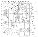
図1〜図2はこの発明の実施例を示すものである。図1において、2は図示しない車両に搭載された駆動源であるエンジン、4はクランク軸、6はダンパ付きフライホイール、8は自動変速機である。 1 to 2 show an embodiment of the present invention. In FIG. 1, 2 is an engine which is a drive source mounted on a vehicle (not shown), 4 is a crankshaft, 6 is a flywheel with a damper, and 8 is an automatic transmission.
この自動変速機8は、変速機ケース10内に第1入力軸12と第2入力軸14と出力軸16とリバースアイドラ軸18と主変速部20と副変速部22とを備え、変速機ケース10下部にオイルパン(図示せず)を装着している。
The automatic transmission 8 includes a
そして、前記第1入力軸12は、一端側をダンパ付きフライホイール6に連結され、途中にオイルポンプ24を設け、他端側に連絡部材26を固定して設けている。このオイルポンプ24は、クランク軸4の回転により駆動されて油圧を発生し、図示しないバルブボディに供給する。
The
また、前記第2入力軸14は、第1入力軸12の他端側の軸線延長上に配置され、第2入力軸軸受28により変速機ケース10に軸支されている。
Further, the
更に、前記出力軸16は、第1入力軸12及び第2入力軸14に平行に配置され、出力軸軸受30により変速機ケース10に軸支されている。
Further, the
前記主変速部20は、第1入力軸12と第2入力軸14との間に配置され、第1入力軸12の回転を第2入力軸14に伝達する。このとき、この主変速部20は、共通のサンギヤ32を有する第1・第2遊星歯車列34・36の2列で構成されるシンプソンタイプである。
The
そして、この第1遊星歯車列34は、第1リングギヤ38と第1ピニオンギヤ40と前記サンギヤ32の第1サンギヤ部42とで構成される。第1リングギヤ38は、第1入力軸12の他端側に対向する第2入力軸14の一端側の軸端において、第2入力軸14周りに回動可能な第1支持部材44の他端側に固定して設けている。第1ピニオンギヤ40は、第1入力軸12の他端側に対向する第2入力軸14の一端側の軸端に固設された第1キャリア46に回動可能に軸支され、前記第1リングギヤ38に噛合する。サンギヤ32は、第2入力軸14の一端側の端部近傍に回動可能に軸支され、一端側に設けられた第1サンギヤ部42を第1ピニオンギヤ40に噛合する。
The first
また、前記第2遊星歯車列36は、第2リングギヤ48と第2ピニオンギヤ50と前記サンギヤ32の第2サンギヤ部52とで構成される。第2リングギヤ48は、サンギヤ32の他端側に近接して第2入力軸14に固設された第2支持部材54外周に固定して設けている。第2ピニオンギヤ50は、第2リングギヤ48内周において第2入力軸14周りに回動可能な第2キャリア56に回動可能に軸支され、前記第2リングギヤ48に噛合する。サンギヤ32は、第1サンギヤ部42と反対の他端側に設けられた第2サンギヤ部52を前記第2ピニオンギヤ50に噛合する。
The second
前記主変速部20は、第1遊星歯車列34の第1リングギヤ38を固定した第1支持部材44の一端側と、第1入力軸12の他端側に固定された連絡部材26の外周との間に、油圧で作動される摩擦式の発進クラッチ58を設けている。
The
また、前記主変速部20は、サンギヤ32の第1・第2サンギヤ部42・52間の外周から径外方向に延びる円環部材60の外周と、この円環部材60外周に対峙する変速機ケース10との間に、油圧で作動される摩擦式のバンドブレーキ62を設けている。
The
更に、前記主変速部20は、円環部材60途中から第1支持部材44方向に延びる円筒部材64先端と、第1支持部材44の途中から径外方向に延びる延長部材66内周との間に、油圧で作動される摩擦式のダイレクトクラッチ68を設けている。
Further, the
更にまた、前記主変速部20は、第2遊星歯車列36の第2キャリヤ56から変速機ケース10方向に延びる環状部材70外周と、この環状部材70外周に対峙する変速機ケース10との間に、逆転方向の回転を阻止するワンウェイクラッチ(「1ウェイクラッチ」ともいう。)72を設けている。
Further, the
前記発進クラッチ58とバンドブレーキ62とダイレクトクラッチ68とは、前記主変速部20を変速操作する摩擦係合要素74を構成し、図示しない発進クラッチ用油圧回路とバンドブレーキ用油圧回路とダイレクトクラッチ用油圧回路との各油圧回路により自動変速機8の図示しない変速制御装置を構成するバルブボディ(図示せず)に連絡されている。
The starting
このバルブボディは、変速機ケース10下部に装着されるオイルパン内に配設され、前記オイルポンプ24がポンプ用油圧回路(図示せず)により連絡されている。
The valve body is disposed in an oil pan attached to the lower portion of the
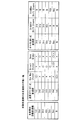
前記変速制御装置は、制御手段(図示せず)によりバルブボディに内蔵された図示しない各制御バルブを動作制御し、オイルポンプ24の発生する油圧を摩擦係合要素74を構成する発進クラッチ58とバンドブレーキ62とダイレクトクラッチ68とに供給・排出して作動を制御し、図2に示す如く、ワンウェイクラッチ72との組み合わせで前記主変速部20を1速から3速までの間で変速操作する。
The speed change control device controls the operation of each control valve (not shown) built in the valve body by a control means (not shown), and the hydraulic pressure generated by the
すなわち、前記主変速部20は、ワンウェイクラッチ72の結合により1速ギヤ段に変速操作され、バンドブレーキ62の結合により2速ギヤ段に変速操作され、ダイレクトクラッチ68の結合により3速ギヤ段に変速操作される。
That is, the
この主変速部20よりも駆動源であるエンジン2から離間する側であって、第2入力軸14と出力軸16との間には、第2入力軸14の回転を出力軸16に伝達する前記副変速部22を設けている。
The rotation of the
この副変速部22は、3速ギヤ段76と4速ギヤ段78と5速ギヤ段80とリバースギヤ段82とからなり、3速ギヤ段76〜5速ギヤ段80を主変速部20に近接する側から離間する側に向かって順次に配設し、3速ギヤ段76と4速ギヤ段78との間にリバースギヤ段82を配設している。
The
前記3速ギヤ段76は、第2入力軸14に固設された第2入力軸側3速ギヤ84と、出力軸16に回動自在に軸支されて第2入力軸側3速ギヤ84に噛合する出力軸側3速ギヤ86とからなる。
The third
前記4速ギヤ段78は、第2入力軸14に固設された第2入力軸側4速ギヤ88と、出力軸16に回動自在に軸支されて第2入力軸側4速ギヤ88に噛合する出力軸側4速ギヤ90とからなる。
The fourth
前記5速ギヤ段80は、第2入力軸14に回動自在に軸支された第2入力軸側5速ギヤ92と、出力軸16に固設されて第2入力軸側5速ギヤ92に噛合する出力軸側5速ギヤ94とからなる。
The fifth
前記リバースギヤ段82は、第2入力軸14に固設された第2入力軸側リバースギヤ96と、後述する3速・4速噛合クラッチ102の3速・4速シフトスリーブ110に一体に設けた出力軸側リバースギヤ98と、第2入力軸側リバースギヤ96及び出力軸側リバースギヤ98に噛合・離脱されるようにリバースアイドラ軸18に軸方向移動自在且つ回動自在に軸支されたリバースアイドラギヤ100とからなる。
The reverse gear stage 82 is provided integrally with a second input shaft-
前記出力軸側3速ギヤ86と出力軸側4速ギヤ90との間の出力軸16には、3速ギヤ段76と4速ギヤ段78とを切り換える切換機構である3速・4速噛合クラッチ102を設けている。
The
この3速・4速噛合クラッチ102は、出力軸側3速ギヤ86に設けた3速ギヤ用係合部104と、出力軸側4速ギヤ90に設けた4速ギヤ用係合部106と、出力軸16に固設された3速・4速ハブ108と、この3速・4速ハブ108に軸方向移動可能且つ回転不能に係合されて3速ギヤ用係合部104及び4速ギヤ用係合部106に選択的に係合・離脱される3速・4速シフトスリーブ110とからなる。
The third-speed / four-
前記3速・4速噛合クラッチ102は、3速・4速シフトスリーブ110を3速ギヤ用係合部104及び4速ギヤ用係合部106に選択的に係合・離脱させることにより、出力軸側3速ギヤ86及び出力軸側4速ギヤ90を出力軸16に対して選択的に固定・解放し、3速ギヤ段76及び4速ギヤ段78のいずれか一方に切り換える。
The three-speed / four-
また、前記第2入力軸側5速ギヤ92の第2入力軸側4速ギヤ88と反対側の第2入力軸14には、5速ギヤ段80に切り換える切換機構である5速噛合クラッチ112を設けている。
Further, the second input shaft side
この5速噛合クラッチ112は、第2入力軸側5速ギヤ92に設けた5速ギヤ用係合部114と、第2入力軸14に固設された5速ハブ116と、この5速ハブ116に軸方向移動可能且つ回転不能に係合されて5速ギヤ用係合部114に係合・離脱される5速シフトスリーブ118とからなる。
The 5-
前記5速噛合クラッチ112は、5速シフトスリーブ118を5速ギヤ用係合部114に係合・離脱させることにより、第2入力軸側5速ギヤ92を第2入力軸14に対して固定・解放し、5速ギヤ段80に切り換える。
The fifth speed meshing clutch 112 fixes the second input shaft side
更に、前記リバースアイドラギヤ100には、リバース切換機構120を設けている。このリバース切換機構120は、リバースアイドラギヤ100にリバースシフトスリーブ122を設けている。
Further, the reverse idler gear 100 is provided with a reverse switching mechanism 120. The reverse switching mechanism 120 is provided with a
そして、前記リバース切換機構120は、リバースシフトスリーブ122によりリバースアイドラギヤ100をリバースアイドラ軸18の軸方向に移動させ、第2入力軸側リバースギヤ96及び出力軸側リバースギヤ98に噛合・離脱させることにより、リバースギヤ段82に切り換える。
Then, the reverse switching mechanism 120 moves the reverse idler gear 100 in the axial direction of the reverse idler shaft 18 by the
前記3速・4速噛合クラッチ102の3速・4速シフトスリーブ110と5速噛合クラッチ112の5速シフトスリーブ118とリバース切換機構120のリバースシフトスリーブ122とは、図示しない3速・4速変速機構と5速変速機構とリバース変速機構とを介してシフトアクチュエータ(図示せず)に連絡されている。
The third speed / fourth
前記変速制御装置は、制御手段(図示せず)によりバルブボディに内蔵された各制御バルブを動作制御し、オイルポンプ24の発生する油圧を各油圧回路により各シリンダに供給・排出して各ピストンの作動を制御し、図2に示す如く、前記副変速部22を3速から5速までの間とリバースとに変速操作する。
The shift control device controls the operation of each control valve built in the valve body by a control means (not shown), and supplies and discharges the hydraulic pressure generated by the
すなわち、副変速部22は、オイルポンプ24の油圧により作動されるシフトアクチュエータによって、3速・4速変速機構と5速変速機構とリバース変速機構とを介して、3速・4速噛合クラッチ102と5速噛合クラッチ112とリバース切換機構120とが操作され、3速ギヤ段76・4速ギヤ段78・5速ギヤ段80・リバースギヤ段82が切り換えられる。
In other words, the
また、前記自動変速機8は、図1に示す如く、出力軸16のエンジン2側端に終減速駆動ギヤ124を設け、この終減速駆動ギヤ124に噛合する終減速従動ギヤ126を差動機128に取り付けて設けている。差動機128には、左右の駆動車軸130・132の一端側を連絡して設けている。駆動車軸130・132は、左右の車軸軸受134・136により変速機ケース10に軸支され、他端側を図示しない左右の駆動車輪に連絡して設けている。
Further, as shown in FIG. 1, the automatic transmission 8 is provided with a final
つまり、前記自動変速機8は、断続可能な発進クラッチ58を介して駆動源であるエンジン2に接続される主変速部20と、この主変速部20から回転が伝達される副変速部22とで構成され、前記主変速部20をサンギヤ32が連結された第1、第2遊星歯車列34、36を有する遊星歯車機構で構成し、前記第1遊星歯車列34の第1リングギヤ38を前記発進クラッチ58に連結し、前記第1遊星歯車列34のプラネタリキャリヤである第1キャリア46及び前記第2遊星歯車列36の第2リングギヤ48を前記遊星歯車機構の出力軸側となるように前記第2入力軸14に連結し、前記第2遊星歯車列36のプラネタリキャリヤである第2キャリア56を1ウェイクラッチ72を介して変速機ケース10に連結するとともに、前記サンギヤ32にはこのサンギヤ32の回転を規制するバンドブレーキ62と前記第1遊星歯車列34の第1リングギヤ38に連結するダイレクトクラッチ68とを設け、前記副変速部22を変速及び、前後進への切換が可能な平行軸式歯車機構で構成している。
In other words, the automatic transmission 8 includes a
このとき、前記平行軸式歯車機構で構成される前記副変速部22を後退段とする際に、前記バンドブレーキ62と前記ダイレクトクラッチ68のうちどちらか一方を作動させた状態とすべく構成する。
At this time, when the
詳述すれば、前記副変速部22を後退段、つまり、オイルポンプ24の油圧により作動されるシフトアクチュエータによって、リバース変速機構を介して、リバース切換機構120を操作し、リバースギヤ段82を切り換えて後退段であるリバース状態とした際に、前記バンドブレーキ62と前記ダイレクトクラッチ68とのいずれか一方を作動させた状態とするものである。
More specifically, the
すなわち、前記自動変速機8において、前記主変速部20を1速状態とした際には、駆動源であるエンジン2から駆動車輪に駆動力を伝達できるが、駆動車輪側から駆動される場合には、サンギヤ32が空転されるだけでエンジン2側に駆動力が伝達されない。
That is, in the automatic transmission 8, when the
よって、前記副変速部22を後退段であるリバース状態とした際に、前記バンドブレーキ62と前記ダイレクトクラッチ68とのいずれか一方を作動させた状態として前記主変速部20を2速段状態または3速状態とし、駆動源であるエンジン2側及びタイヤ側の両方向からの駆動力伝達の可能な構成とするものである。
Therefore, when the
次に作用を説明する。 Next, the operation will be described.
自動変速機8は、シンプソン式の遊星歯車機構に前後進への切換が可能な平行軸式歯車機構を組み合わせ、遊星歯車機構で1速から3速までの前進段を達成するとともに、平行軸式歯車機構で4速及び5速の前進段と後退段とを達成するように構成されている。 The automatic transmission 8 combines a Simpson type planetary gear mechanism with a parallel shaft type gear mechanism capable of switching to forward / reverse, achieves a forward gear from the first speed to the third speed with the planetary gear mechanism, The gear mechanism is configured to achieve the forward speed and the reverse speed of the fourth speed and the fifth speed.
この場合、シンプソン式の遊星歯車機構は、共通のサンギヤを有する第1・第2遊星歯車列の2列で構成され、第1遊星歯車列のリングギヤを第1入力軸に連結し、第1遊星歯車列のプラネタリキャリヤ及び第2遊星歯車列のリングギヤを遊星歯車機構の出力部(第2出力軸)に連結し、第2遊星歯車列のプラネタリキャリヤを1ウェイクラッチを介して変速機ケースに連結し、前記サンギヤにはこのサンギヤの回転を規制するバンドブレーキ62を設けるとともに、第1遊星歯車列のリングギヤに連結するダイレクトクラッチ68を設けている。
In this case, the Simpson type planetary gear mechanism is composed of two rows of first and second planetary gear trains having a common sun gear, and the ring gear of the first planetary gear train is connected to the first input shaft, and the first planetary gear train is provided. The planetary carrier of the gear train and the ring gear of the second planetary gear train are connected to the output part (second output shaft) of the planetary gear mechanism, and the planetary carrier of the second planetary gear train is connected to the transmission case via the one-way clutch. The sun gear is provided with a
そして、前記平行軸式歯車機構で構成される前記副変速部22を後退段とする際には、前記バンドブレーキ62と前記ダイレクトクラッチ68のうちどちらか一方を作動させた状態とする。
When the
つまり、前記オイルポンプ24の油圧により作動されるシフトアクチュエータによって、リバース変速機構を介して、リバース切換機構120を操作し、リバースギヤ段82を切り換えて後退段であるリバース状態とした際に、前記バンドブレーキ62と前記ダイレクトクラッチ68とのいずれか一方を作動させて前記主変速部20を2速段状態または3速状態とし、駆動車輪側からエンジン2側に駆動力を伝達可能とし、エンジンブレーキを作動させることができる。
That is, when the reverse switching mechanism 120 is operated via the reverse transmission mechanism by the shift actuator operated by the oil pressure of the
追記すれば、前記副変速部22を後退段とした際に、図2に示す如く、バンドブレーキ62を作動状態、つまり「○」印にするとともに、前記ダイレクトクラッチ68を非作動状態、つまり「X」印にした場合、主変速部20が2速段状態となる。
In addition, as shown in FIG. 2, when the
逆に、前記副変速部22を後退段とした際に、図2のかっこ内に示す如く、ダイレクトクラッチ68を作動状態、つまり「○」印にするとともに、前記バンドブレーキ62を非作動状態、つまり「X」印にした場合、主変速部20が3速段状態となる。
On the contrary, when the
この発明の自動変速機は、変速部が遊星歯車機構と前進及び後退の切換が可能な平行軸式歯車機構とで構成された自動変速機について、遊星歯車機構の変速装置を簡素化させつつ、後退時にエンジンブレーキを作動させるものである。 The automatic transmission of the present invention is an automatic transmission having a planetary gear mechanism and a parallel shaft gear mechanism capable of switching between forward and reverse, while simplifying the transmission device of the planetary gear mechanism. The engine brake is actuated during reverse.
2 駆動源であるエンジン
4 クランク軸
6 ダンパ付きフライホイール
8 自動変速機
10 変速機ケース
12 第1入力軸
14 第2入力軸
16 出力軸
18 リバースアイドラ軸
20 主変速部
22 副変速部
24 オイルポンプ
26 連絡部材
28 第2入力軸軸受
30 出力軸軸受
32 サンギヤ
34 第1遊星歯車列
36 第2遊星歯車列
38 第1リングギヤ
40 第1ピニオンギヤ
42 第1サンギヤ部
46 第1キャリア
48 第2リングギヤ
50 第2ピニオンギヤ
52 第2サンギヤ部
56 第2キャリア
58 発進クラッチ
62 バンドブレーキ
68 ダイレクトクラッチ
72 ワンウェイクラッチ(「1ウェイクラッチ」ともいう。)
74 摩擦係合要素
76 3速ギヤ段
78 4速ギヤ段
80 5速ギヤ段
82 リバースギヤ段
84 第2入力軸側3速ギヤ
86 出力軸側3速ギヤ
88 第2入力軸側4速ギヤ
90 出力軸側4速ギヤ
92 第2入力軸側5速ギヤ
94 出力軸側5速ギヤ
96 第2入力軸側リバースギヤ
98 出力軸側リバースギヤ
100 リバースアイドラギヤ
102 3速・4速噛合クラッチ
104 3速ギヤ用係合部
106 4速ギヤ用係合部
108 3速・4速ハブ
110 3速・4速シフトスリーブ
112 5速噛合クラッチ
114 5速ギヤ用係合部
116 5速ハブ
118 5速シフトスリーブ
120 リバース切換機構
122 リバースシフトスリーブ
128 差動機
DESCRIPTION OF
74
Claims (1)
Priority Applications (1)
| Application Number | Priority Date | Filing Date | Title |
|---|---|---|---|
| JP2005002078A JP2006189111A (en) | 2005-01-07 | 2005-01-07 | Automatic transmission |
Applications Claiming Priority (1)
| Application Number | Priority Date | Filing Date | Title |
|---|---|---|---|
| JP2005002078A JP2006189111A (en) | 2005-01-07 | 2005-01-07 | Automatic transmission |
Publications (1)
| Publication Number | Publication Date |
|---|---|
| JP2006189111A true JP2006189111A (en) | 2006-07-20 |
Family
ID=36796507
Family Applications (1)
| Application Number | Title | Priority Date | Filing Date |
|---|---|---|---|
| JP2005002078A Pending JP2006189111A (en) | 2005-01-07 | 2005-01-07 | Automatic transmission |
Country Status (1)
| Country | Link |
|---|---|
| JP (1) | JP2006189111A (en) |
Cited By (7)
| Publication number | Priority date | Publication date | Assignee | Title |
|---|---|---|---|---|
| JP2009074621A (en) * | 2007-09-21 | 2009-04-09 | Nissan Motor Co Ltd | Parallel shaft type gear transmission device |
| KR101035247B1 (en) | 2008-10-17 | 2011-05-18 | 현대 파워텍 주식회사 | Automatic manual transmission |
| KR101181897B1 (en) | 2009-08-25 | 2012-09-11 | 현대 파워텍 주식회사 | Automatic manual transmission |
| CN103615507A (en) * | 2013-12-12 | 2014-03-05 | 合肥工业大学 | Gear transmission mechanism used for five-gear transversely-placed automatic transmission |
| KR101417670B1 (en) * | 2013-08-12 | 2014-07-08 | 현대자동차주식회사 | Automated manual transmission |
| DE102008020956B4 (en) * | 2007-04-26 | 2015-05-13 | Suzuki Motor Corp. | Vehicle transmission control device |
| CN113236731A (en) * | 2021-05-10 | 2021-08-10 | 柳工柳州传动件有限公司 | Planetary gearbox and electric engineering machinery |
-
2005
- 2005-01-07 JP JP2005002078A patent/JP2006189111A/en active Pending
Cited By (8)
| Publication number | Priority date | Publication date | Assignee | Title |
|---|---|---|---|---|
| DE102008020956B4 (en) * | 2007-04-26 | 2015-05-13 | Suzuki Motor Corp. | Vehicle transmission control device |
| JP2009074621A (en) * | 2007-09-21 | 2009-04-09 | Nissan Motor Co Ltd | Parallel shaft type gear transmission device |
| KR101035247B1 (en) | 2008-10-17 | 2011-05-18 | 현대 파워텍 주식회사 | Automatic manual transmission |
| KR101181897B1 (en) | 2009-08-25 | 2012-09-11 | 현대 파워텍 주식회사 | Automatic manual transmission |
| KR101417670B1 (en) * | 2013-08-12 | 2014-07-08 | 현대자동차주식회사 | Automated manual transmission |
| CN103615507A (en) * | 2013-12-12 | 2014-03-05 | 合肥工业大学 | Gear transmission mechanism used for five-gear transversely-placed automatic transmission |
| CN113236731A (en) * | 2021-05-10 | 2021-08-10 | 柳工柳州传动件有限公司 | Planetary gearbox and electric engineering machinery |
| CN113236731B (en) * | 2021-05-10 | 2023-01-06 | 柳工柳州传动件有限公司 | Planetary gearbox and electric engineering machinery |
Similar Documents
| Publication | Publication Date | Title |
|---|---|---|
| JP4973487B2 (en) | Multiple clutch transmission | |
| KR20050069000A (en) | A six-speed power train of an automatic transmission for a vehicle | |
| JP2006189111A (en) | Automatic transmission | |
| JP2006194435A (en) | Starting clutch device and automatic transmission | |
| JP2008232246A (en) | Transmission for industrial vehicle | |
| KR100820193B1 (en) | A 8 speed power train of an automatic transmission | |
| KR20070121246A (en) | A 8 speed power train of an automatic transmission | |
| KR100764715B1 (en) | A 8 speed power train of an automatic transmission | |
| KR100828597B1 (en) | A 6 speed power train of an automatic transmission | |
| JP2017193260A (en) | Driving device for vehicle | |
| KR100836085B1 (en) | A 8 speed power train of an automatic transmission | |
| JP4032794B2 (en) | Automatic transmission | |
| JP2006183739A (en) | Transmission case structure | |
| KR100872440B1 (en) | A 8th-speed power train of an automatic transmission | |
| CN215634756U (en) | Planet row type transmission and vehicle | |
| US9541171B2 (en) | Automatic transmission for vehicles | |
| JP2005133877A (en) | Automatic transmission for vehicle | |
| JP7005352B2 (en) | Stepped transmission | |
| KR101230823B1 (en) | A 7 speed power train of an automatic transmission | |
| KR20080099010A (en) | A 8th-speed power train of an automatic transmission | |
| JP2006125547A (en) | Speed controller for automatic transmission | |
| JPS62242165A (en) | Transmission for vehicle | |
| KR100836087B1 (en) | A 6 speed power train of an automatic transmission | |
| JP2004293770A (en) | Automatic transmission for vehicle | |
| KR100623777B1 (en) | A 6th-SPEED POWER TRAIN OF AN AUTOMATIC TRANSMISSION FOR A VEHICLE |