JP2006187721A - Dehumidifier - Google Patents

Dehumidifier Download PDF

Info

Publication number
JP2006187721A
JP2006187721A JP2005001215A JP2005001215A JP2006187721A JP 2006187721 A JP2006187721 A JP 2006187721A JP 2005001215 A JP2005001215 A JP 2005001215A JP 2005001215 A JP2005001215 A JP 2005001215A JP 2006187721 A JP2006187721 A JP 2006187721A
Authority
JP
Japan
Prior art keywords
moisture
air
amount
auxiliary heating
ambient temperature
Prior art date
Legal status (The legal status is an assumption and is not a legal conclusion. Google has not performed a legal analysis and makes no representation as to the accuracy of the status listed.)
Pending
Application number
JP2005001215A
Other languages
Japanese (ja)
Inventor
Kazumasa Mizukami
和昌 水上
Yoshimasa Katsumi
佳正 勝見
Yasuki Fujii
泰樹 藤井
Current Assignee (The listed assignees may be inaccurate. Google has not performed a legal analysis and makes no representation or warranty as to the accuracy of the list.)
Panasonic Holdings Corp
Original Assignee
Matsushita Electric Industrial Co Ltd
Priority date (The priority date is an assumption and is not a legal conclusion. Google has not performed a legal analysis and makes no representation as to the accuracy of the date listed.)
Filing date
Publication date
Application filed by Matsushita Electric Industrial Co Ltd filed Critical Matsushita Electric Industrial Co Ltd
Priority to JP2005001215A priority Critical patent/JP2006187721A/en
Publication of JP2006187721A publication Critical patent/JP2006187721A/en
Pending legal-status Critical Current

Links

Images

Landscapes

  • Drying Of Gases (AREA)

Abstract

<P>PROBLEM TO BE SOLVED: To provide a dehumidifier capable of realizing the efficient dehumidification effect by controlling the purge air volume of the dehumidifier capable of performing efficient dehumidification with a simple configuration without any circulation path 111 by using a heat pump 118 and a moisture absorbing/releasing means 119. <P>SOLUTION: The dehumidifier comprises a heat pump (118) having a compressor (102), a radiator (103), an expansion mechanism (104), and a heat sink (105), a moisture absorbing/releasing means (119) having a moisture absorbing unit (120) to absorb the moisture from supplied air and a moisture releasing unit (121) to release the moisture to the supplied air, and a purged air volume adjustment means (9) which supplies air (116) for dehumidification is supplied to the radiator (103), the moisture releasing unit (121), the heat sink (105) and the moisture absorbing unit (120) in this order, supplies purged air (4) to the moisture absorbing unit (120), and adjusts the volume of the purged air (4). <P>COPYRIGHT: (C)2006,JPO&NCIPI

Description

本発明は、圧縮機、放熱器、膨張機構、吸熱器等から構成されるヒートポンプと、吸着剤や吸収剤を用いて吸放湿を行う吸放湿手段を備えた除湿装置に関する。   The present invention relates to a dehumidifying apparatus including a heat pump including a compressor, a radiator, an expansion mechanism, a heat absorber, and the like, and a moisture absorption / release unit that performs moisture absorption / release using an adsorbent or an absorbent.

従来のヒートポンプと吸放湿手段を備えた除湿装置としては、放熱器、吸放湿手段の放湿部、吸熱器の順に空気を循環させるものがある(例えば、特許文献1参照)。   As a conventional dehumidifying device including a heat pump and moisture absorbing / releasing means, there is an apparatus that circulates air in the order of a radiator, a moisture releasing part of the moisture absorbing / releasing means, and a heat absorber (see, for example, Patent Document 1).

以下、その除湿装置について図10を参照しながら説明する。   Hereinafter, the dehumidifier will be described with reference to FIG.

図10に示すように、除湿装置の本体100内には、圧縮機102、放熱器103、膨張機構104、吸熱器105を配管接続した冷媒回路106と、吸着剤107が担持されたハニカムローター108が設けられており、循環ファン109によって送風される循環空気110が、放熱器103、ハニカムローター108の一部、吸熱器105の順に循環するように循環経路111が形成されている。また、ハニカムローター108の他の部分は、吸込口112および吹出口113を開口した供給経路114内に配置されており、供給ファン115によって除湿対象空気116が供給されている。また、冷媒回路106内には冷媒117が充填されており、この冷媒117が、圧縮機102で圧縮されることによって、放熱器103、膨張機構104、吸熱器105の順に冷媒回路106内を循環し、放熱器103において循環空気110に放熱するとともに、吸熱器105において循環空気110から吸熱することによってヒートポンプ118を動作させている。ハニカムローター108は、図示しない駆動手段によって回転しており、この回転に伴いハニカムローター108に担持された吸着剤107が、循環経路111内における循環空気110との接触と供給経路114内における除湿対象空気116との接触を繰り返している。この吸着剤107は、晒される空気の相対湿度が高ければ多くの水分を保持でき、相対湿度が低くなると保持可能な水分量が減少する特性を有しているので、相対湿度の異なる複数の空気との接触を繰り返せば、各々の相対湿度における吸着剤107の保持可能な水分量の差に応じて水分の吸脱着が行われることになる。ここで、循環経路111内で吸着剤107と接触する循環空気110は、放熱器103において冷媒117の放熱により加熱されて除湿対象空気116よりも低い相対湿度の空気となっているので、この相対湿度の差によって、吸着剤107が、除湿対象空気116中の水分を吸着し、吸着した水分を循環空気110中に脱着するように作用する。この吸脱着作用によって吸放湿手段119としての動作がなされることとなり、ハニカムローター108の供給経路114内に位置する部分が除湿対象空気116から吸湿する吸湿部120、ハニカムローター108の循環経路111内に位置する部分が循環空気110へ放湿する放湿部121となる。吸湿部120において吸湿された除湿対象空気116は低湿の空気となって吹出口113から本体101外部に吹出し、放湿部121において放湿された循環空気110は、高湿の空気となって吸熱器105に供給される。吸熱器105に供給された高湿の循環空気110は、冷媒117の吸熱によって露点温度以下まで冷却されて空気中の水分が飽和する。この飽和した水分が凝縮してタンク122に滴下し、このタンク122に溜まった凝縮水の量が除湿装置の除湿量となるのである。
特開昭63−1423号公報(第2−3頁、第1図)
As shown in FIG. 10, in the main body 100 of the dehumidifying device, a refrigerant circuit 106 in which a compressor 102, a radiator 103, an expansion mechanism 104, and a heat absorber 105 are connected by piping, and a honeycomb rotor 108 on which an adsorbent 107 is supported. The circulation path 111 is formed so that the circulation air 110 blown by the circulation fan 109 circulates in the order of the radiator 103, a part of the honeycomb rotor 108, and the heat absorber 105. Further, the other part of the honeycomb rotor 108 is disposed in a supply path 114 that opens the suction port 112 and the air outlet 113, and the dehumidification target air 116 is supplied by the supply fan 115. In addition, the refrigerant circuit 106 is filled with a refrigerant 117, and the refrigerant 117 is compressed by the compressor 102, and thus circulates in the refrigerant circuit 106 in the order of the radiator 103, the expansion mechanism 104, and the heat absorber 105. In addition, the heat pump 118 is operated by radiating heat to the circulating air 110 in the radiator 103 and absorbing heat from the circulating air 110 in the heat absorber 105. The honeycomb rotor 108 is rotated by a driving means (not shown), and the adsorbent 107 carried on the honeycomb rotor 108 with this rotation is brought into contact with the circulating air 110 in the circulation path 111 and to be dehumidified in the supply path 114. The contact with the air 116 is repeated. This adsorbent 107 has a characteristic that it can retain a large amount of moisture if the relative humidity of the exposed air is high, and the amount of water that can be retained decreases when the relative humidity is low. If the contact is repeated, moisture adsorption / desorption is performed according to the difference in the amount of moisture that can be held by the adsorbent 107 at each relative humidity. Here, the circulating air 110 in contact with the adsorbent 107 in the circulation path 111 is heated by the heat radiation of the refrigerant 117 in the radiator 103 and becomes air having a relative humidity lower than that of the air to be dehumidified 116. Due to the difference in humidity, the adsorbent 107 acts to adsorb moisture in the dehumidified air 116 and desorb the adsorbed moisture into the circulating air 110. This absorption / desorption action causes the moisture absorption / release means 119 to operate, and a portion located in the supply path 114 of the honeycomb rotor 108 absorbs moisture from the dehumidification target air 116, and the circulation path 111 of the honeycomb rotor 108. The part located inside becomes the moisture releasing part 121 that releases moisture to the circulating air 110. The air to be dehumidified 116 absorbed in the moisture absorption part 120 is blown out of the main body 101 from the air outlet 113 as low-humidity air, and the circulating air 110 dehumidified in the moisture release part 121 becomes high-humidity air and absorbs heat. Is supplied to the vessel 105. The high-humidity circulating air 110 supplied to the heat absorber 105 is cooled to the dew point temperature or less by the heat absorption of the refrigerant 117, and the moisture in the air is saturated. This saturated water is condensed and dropped into the tank 122, and the amount of condensed water accumulated in the tank 122 becomes the dehumidifying amount of the dehumidifying device.
JP 63-1423 (page 2-3, Fig. 1)

以上の例では、吸湿部120において除湿対象空気116から吸湿し、この吸湿した水分を、放熱器103で加熱した高温の循環空気110を放湿部121に供給することによって放湿させ、この放湿させた水分を含んだ高湿の循環空気110を吸熱器105において冷却して水分を飽和させるとことにより除湿するようにしている。したがって循環空気110を放熱器103、放湿部121、吸熱器105に循環させる循環経路111を密閉性よく本体101内に形成する必要があり、装置構成が複雑化するという問題点があった。そして循環経路111の密閉度が低い場合には、除湿対象空気116と循環空気110との湿度移行が発生して除湿効率が低下するという課題があり、除湿効率を向上させることが要求されている。また除湿装置の使用環境が悪い場合は、機器に対して大きな負荷がかかり、効率低下や故障の原因となるという課題があり、使用環境の悪いときでも安全に安定して使用できることが要求されている。   In the above example, the moisture absorption unit 120 absorbs moisture from the dehumidification target air 116, and the moisture absorbed is supplied to the moisture release unit 121 by supplying the high-temperature circulating air 110 heated by the radiator 103 to the moisture release unit 121. The high-humidity circulating air 110 containing the moistened water is cooled in the heat absorber 105 to saturate the water, thereby dehumidifying. Therefore, the circulation path 111 for circulating the circulating air 110 to the radiator 103, the moisture release unit 121, and the heat absorber 105 needs to be formed in the main body 101 with good airtightness, and there is a problem that the apparatus configuration is complicated. And when the sealing degree of the circulation path 111 is low, there exists a subject that humidity transfer with the dehumidification object air 116 and the circulation air 110 generate | occur | produces and dehumidification efficiency falls, and improving dehumidification efficiency is requested | required. . Also, when the usage environment of the dehumidifier is bad, there is a problem that a heavy load is applied to the equipment, causing a decrease in efficiency and a failure, and it is required that it can be used safely and stably even when the usage environment is bad. Yes.

本発明は上記課題を解決するものであり、循環経路111のない単純な構成で、効率の良い除湿が行え、使用環境が悪い場合でも機器を損傷することなく、安全かつ安定して運転できる除湿装置を提供することを目的としている。   The present invention solves the above-mentioned problems, and can perform efficient dehumidification with a simple configuration without the circulation path 111, and can perform safe and stable operation without damaging the equipment even in a poor use environment. The object is to provide a device.

上記した目的を達成するために、本発明が講じた第1の課題解決手段は、冷媒(117)を圧縮する圧縮機(102)と前記冷媒(117)が供給空気に対して放熱する放熱器(103)と前記冷媒(117)が膨張する膨張機構(104)と前記冷媒(117)が供給空気から吸熱する吸熱器(105)とを有するヒートポンプ(118)と、供給空気から吸湿する吸湿部(120)および供給空気に補助加熱部(5)に加熱されて放湿する放湿部(121)を有する吸放湿手段(119)と、除湿対象空気(116)を前記放熱器(103)、前記放湿部(121)、前記吸熱器(105)、前記吸湿部(120)の順に供給するとともに、前記吸湿部(120)にパージ空気(4)を供給する構成とし、前記パージ空気(4)の量を調整するパージ空気量調整手段(9)を有したものである。   In order to achieve the above object, the first problem-solving means taken by the present invention includes a compressor (102) that compresses the refrigerant (117) and a radiator that radiates heat to the supply air from the refrigerant (117). (103), a heat pump (118) having an expansion mechanism (104) for expanding the refrigerant (117), and a heat absorber (105) for the refrigerant (117) to absorb heat from the supply air, and a moisture absorption part for absorbing moisture from the supply air (120) and a moisture absorbing / releasing means (119) having a moisture releasing part (121) that is heated by the auxiliary heating part (5) to the supplied air to release moisture, and the dehumidifying target air (116) is the radiator (103) The moisture release unit (121), the heat absorber (105), and the moisture absorption unit (120) are supplied in this order, and purge air (4) is supplied to the moisture absorption unit (120). Adjust the amount of 4) Those having a purge air quantity adjusting means (9) to.

また、本発明が講じた第2の課題解決手段は、上記第1の課題解決手段において、パージ空気量調整手段(9)を室温検知手段(30)の出力に応じて制御する構成としたものである。   Further, the second problem solving means adopted by the present invention is configured such that the purge air amount adjusting means (9) is controlled in accordance with the output of the room temperature detecting means (30) in the first problem solving means. It is.

また、本発明が講じた第3の課題解決手段は、上記第1の課題解決手段において、パージ空気量調整手段(9)を放湿部周辺温度検知手段(31)の出力に応じて制御する構成としたものである。   The third problem solving means provided by the present invention controls the purge air amount adjusting means (9) in accordance with the output of the moisture release portion ambient temperature detecting means (31) in the first problem solving means. It is a configuration.

また、本発明が講じた第4の課題解決手段は、上記第1の課題解決手段において、パージ空気量調整手段(9)を補助加熱部周辺温度検知手段(32)の出力に応じて制御する構成としたものである。   According to a fourth problem solving means provided by the present invention, in the first problem solving means, the purge air amount adjusting means (9) is controlled according to the output of the auxiliary heating part ambient temperature detecting means (32). It is a configuration.

また、本発明が講じた第5の課題解決手段は、上記第1の課題解決手段において、パージ空気量調整手段(9)を補助加熱部(5)の加熱量に応じて制御する構成としたものである。   Further, the fifth problem solving means provided by the present invention is configured to control the purge air amount adjusting means (9) according to the heating amount of the auxiliary heating section (5) in the first problem solving means. Is.

また、本発明が講じた第6の課題解決手段は、上記第1の課題解決手段において、パージ空気量調整手段(9)を室温検知手段(30)と放湿部周辺温度検知手段(31)の出力に応じて制御する構成としたものである。   The sixth problem solving means provided by the present invention is the same as the first problem solving means described above, except that the purge air amount adjusting means (9) is replaced with a room temperature detecting means (30) and a moisture release portion ambient temperature detecting means (31). It is set as the structure controlled according to the output of this.

また、本発明が講じた第7の課題解決手段は、上記第1の課題解決手段において、パージ空気量調整手段(9)を室温検知手段(30)と補助加熱部周辺温度検知手段(32)の出力に応じて制御する構成としたものである。   The seventh problem solving means provided by the present invention is the same as the first problem solving means, except that the purge air amount adjusting means (9) is replaced with a room temperature detecting means (30) and an auxiliary heating part ambient temperature detecting means (32). It is set as the structure controlled according to the output of this.

また、本発明が講じた第8の課題解決手段は、上記第1の課題解決手段において、パージ空気量調整手段(9)を室温検知手段(30)の出力と補助加熱部(5)の加熱量に応じて制御する構成としたものである。   The eighth problem-solving means provided by the present invention is the same as the first problem-solving means, except that the purge air amount adjusting means (9) is replaced with the output of the room temperature detecting means (30) and the heating of the auxiliary heating section (5). It is set as the structure controlled according to quantity.

また、本発明が講じた第9の課題解決手段は、上記第1の課題解決手段において、パージ空気量調整手段(9)を放湿部周辺温度検知手段(31)と補助加熱部周辺温度検知手段(32)の出力に応じて制御する構成としたものである。   Further, a ninth problem solving means provided by the present invention is the same as the first problem solving means described above, wherein the purge air amount adjusting means (9) is replaced with a moisture releasing part ambient temperature detecting means (31) and an auxiliary heating part ambient temperature detecting. The control is performed according to the output of the means (32).

また、本発明が講じた第10の課題解決手段は、上記第1の課題解決手段において、パージ空気量調整手段(9)を室温検知手段(30)と放湿部周辺温度検知手段(31)と補助加熱部周辺温度検知手段(32)の出力に応じて制御する構成としたものである。   The tenth problem solving means provided by the present invention is the same as the first problem solving means described above, except that the purge air amount adjusting means (9) is replaced with a room temperature detecting means (30) and a moisture release portion ambient temperature detecting means (31). And it is set as the structure controlled according to the output of an auxiliary heating part ambient temperature detection means (32).

また、本発明が講じた第11の課題解決手段は、上記第1の課題解決手段において、パージ空気量調整手段(9)を室温検知手段(30)と放湿部周辺温度検知手段(31)と補助加熱部周辺温度検知手段(32)の出力と補助加熱部(5)の加熱量に応じて制御する構成としたものである。   The eleventh problem solving means provided by the present invention is the same as the first problem solving means described above, except that the purge air amount adjusting means (9) is replaced with a room temperature detecting means (30) and a moisture release portion ambient temperature detecting means (31). And it is set as the structure controlled according to the output of an auxiliary | assistant heating part periphery temperature detection means (32), and the heating amount of an auxiliary | assistant heating part (5).

これらの手段により、循環経路111のない単純な構成で、効率の良い除湿が行え、使用環境が悪い場合でも機器を損傷することなく、安全かつ安定して運転できる除湿装置が得られる構成としたものである。   By these means, a simple configuration without the circulation path 111 can be used to efficiently perform dehumidification, and a dehumidification device can be obtained that can be operated safely and stably without damaging the equipment even when the usage environment is bad. Is.

本願発明は、かかる構成とすることにより以下に記載されるような効果を奏するものである。   By adopting such a configuration, the present invention has the following effects.

(イ)本願の第1の発明にかかる除湿装置によれば、放湿部(121)には放熱器(103)で加熱された低い相対湿度の除湿対象空気(116)を供給し、吸湿部(120)には吸熱器(105)において冷却された高い相対湿度の除湿対象空気(116)を供給できる。これにより、吸湿部(120)と放湿部(121)に供給される空気の相対湿度の差を拡大することができる。この相対湿度の差の拡大によって吸放湿手段(119)の吸放湿量を増大させ、除湿効率を高めることができる。さらにパージ空気(4)によって吸着剤(107)が予熱されてから放湿部(121)に移動するので、吸湿部(120)における除湿対象空気(116)からの水分吸着量が増加するとともに、放湿部(121)における除湿対象空気(116)への水分脱着量が増加することになるように調節することができる。   (I) According to the dehumidifying device of the first invention of the present application, the dehumidifying part (121) is supplied with the dehumidification target air (116) having a low relative humidity heated by the radiator (103), and the hygroscopic part (120) can be supplied with dehumidification target air (116) having a high relative humidity cooled in the heat absorber (105). Thereby, the difference of the relative humidity of the air supplied to a moisture absorption part (120) and a moisture release part (121) can be expanded. By increasing the difference in relative humidity, the moisture absorption / release amount of the moisture absorption / release means (119) can be increased, and the dehumidification efficiency can be increased. Furthermore, since the adsorbent (107) is preheated by the purge air (4) and then moves to the moisture release section (121), the amount of moisture adsorbed from the dehumidification target air (116) in the moisture absorption section (120) increases, It can adjust so that the moisture desorption amount to the dehumidification object air (116) in the moisture release part (121) may increase.

(ロ)また、本願の第2の発明にかかる除湿装置によれば、過負荷条件温度の室温では、パージ空気(4)を減らし、放熱器(103)の通風風量を増加させ、高室温においても連続運転が可能とすることができ、除湿量を増加させることができる。   (B) Further, according to the dehumidifying device of the second invention of the present application, the purge air (4) is reduced at the room temperature of the overload condition temperature, the ventilation air volume of the radiator (103) is increased, and the room temperature is high. Can be continuously operated, and the amount of dehumidification can be increased.

(ハ)また、本願の第3の発明にかかる除湿装置によれば、放湿部(121)における除湿対象空気(116)への水分脱着量が増加することになり、除湿量を最大するとともに、放湿部周辺温度が最大温度を超える場合は、放湿部周辺温度を下げるように調節することにより、除湿運転を連続運転させることが可能となり、除湿量を増加させることが可能である。   (C) Further, according to the dehumidifying device of the third invention of the present application, the moisture desorption amount to the dehumidifying target air (116) in the moisture releasing section (121) is increased, and the dehumidifying amount is maximized. When the ambient temperature of the moisture release part exceeds the maximum temperature, the dehumidification operation can be continuously performed by adjusting the moisture release part ambient temperature so as to increase the dehumidification amount.

(ニ)また、本願の第4の発明にかかる除湿装置によれば、放湿部(121)における除湿対象空気(116)への水分脱着量が増加することになり、除湿量を最大するとともに、放湿部周辺温度が最大温度を超える場合は、補助加熱部周辺温度を下げるようにパージ空気(4)量および補助加熱部(5)出力の調節することにより、除湿運転を連続運転させることが可能となり、除湿量を増加させることが可能である。   (D) Further, according to the dehumidifying device of the fourth invention of the present application, the moisture desorption amount to the dehumidifying target air (116) in the moisture releasing portion (121) is increased, and the dehumidifying amount is maximized. When the ambient temperature of the moisture release unit exceeds the maximum temperature, the dehumidifying operation is continuously operated by adjusting the amount of purge air (4) and the output of the auxiliary heating unit (5) so as to lower the ambient temperature of the auxiliary heating unit. And the dehumidification amount can be increased.

(ホ)また、本願の第5の発明にかかる除湿装置によれば、補助加熱部(5)の出力を低下させても、補助加熱部周辺の温度を最大にするように調整し、効率的な運転に調整することが可能となるものである。   (E) Further, according to the dehumidifying device of the fifth invention of the present application, even if the output of the auxiliary heating unit (5) is reduced, the temperature around the auxiliary heating unit is adjusted to be maximized, which is efficient. It is possible to adjust to a safe operation.

(ヘ)また、本願の第6の発明にかかる除湿装置によれば、過負荷条件での連続運転や、高温部の保護を行いながらの除湿運転を連続的に運転が可能であり、効率的な運転が可能となる。   (F) Further, according to the dehumidifying device of the sixth invention of the present application, continuous operation under overload conditions and dehumidifying operation while protecting the high temperature part can be continuously performed, which is efficient. Driving becomes possible.

(ト)また、本願の第7の発明にかかる除湿装置によれば、放湿部周辺温度が最大温度を超える場合は、補助加熱部周辺温度を下げるようにパージ空気(4)量および補助加熱部(5)出力の調節することにより、除湿運転を連続運転させ、かつ連続運転が可能となるものである。   (G) Further, according to the dehumidifying device of the seventh invention of the present application, when the ambient temperature of the moisture release part exceeds the maximum temperature, the amount of purge air (4) and the auxiliary heating so as to lower the ambient temperature of the auxiliary heating part By adjusting the output of the part (5), the dehumidifying operation can be continuously performed and the continuous operation can be performed.

(チ)また、本願の第8の発明にかかる除湿装置によれば、補助加熱部(5)の出力を低下させても、室温の状態を検知してパージ空気(4)量を調整し、補助加熱部周辺の温度を最大にするように調整することにより、効率的な運転に調整することが可能となるものである。   (H) Further, according to the dehumidifying device of the eighth invention of the present application, even if the output of the auxiliary heating unit (5) is reduced, the state of the room temperature is detected and the amount of purge air (4) is adjusted, By adjusting so that the temperature around the auxiliary heating unit is maximized, it is possible to adjust to an efficient operation.

(リ)また、本願の第9の発明にかかる除湿装置によれば、放湿部周辺温度検知手段(31)により、放湿部周辺最大温度を超える場合は、補助加熱部周辺温度を下げるようにパージ空気(4)量および補助加熱部(5)出力の調節することにより、除湿運転を連続運転させ、高温部の保護を行いながらの除湿運転を連続的に運転が可能であり、かつ効率的な運転が可能となるものである。   (Li) Further, according to the dehumidifying device of the ninth invention of the present application, when the maximum temperature around the moisture release unit is exceeded by the moisture release unit ambient temperature detection means (31), the ambient temperature around the auxiliary heating unit is lowered. By adjusting the amount of purge air (4) and the output of the auxiliary heating unit (5), the dehumidifying operation can be continuously operated, and the dehumidifying operation can be continuously performed while protecting the high temperature part, and the efficiency. Operation is possible.

(ヌ)また、本願の第10の発明にかかる除湿装置によれば、放湿部周辺温度検知手段(31)により、放湿部周辺最大温度を超える場合は、補助加熱部周辺温度を下げるようにパージ空気(4)量および補助加熱部(5)出力の調節することにより、除湿運転を連続運転させ、過負荷条件での連続運転や、高温部の保護を行いながらの除湿運転を連続的に運転が可能であり、かつ効率的な運転が可能となるものである。   (Nu) Further, according to the dehumidifying device of the tenth invention of the present application, when the maximum temperature around the moisture release unit is exceeded by the moisture release unit ambient temperature detection means (31), the ambient temperature around the auxiliary heating unit is lowered. By adjusting the amount of purge air (4) and the output of the auxiliary heating unit (5), the dehumidifying operation is continuously operated, and continuous operation under overload conditions and dehumidifying operation while protecting the high temperature part are continuously performed. In addition, it is possible to operate efficiently and efficiently.

(ル)また、本願の第11の発明にかかる除湿装置によれば、放湿部周辺温度検知手段(31)により、放湿部周辺最大温度を超える場合は、補助加熱部周辺温度を下げるようにパージ空気(4)量および補助加熱部(5)出力の調節することにより、除湿運転を連続運転させ、過負荷条件での連続運転や、高温部の保護を行いながらの除湿運転を連続的に運転が可能であり、また補助加熱部(5)の出力を低下させても、室温の状態を検知してパージ空気(4)量を調整し、補助加熱部周辺の温度を最大にするように調整することにより、効率的な運転に調整することが可能となるものである。   (L) Further, according to the dehumidifying device of the eleventh invention of the present application, when the maximum temperature around the moisture release part is exceeded by the moisture release part ambient temperature detection means (31), the auxiliary heating part ambient temperature is lowered. By adjusting the amount of purge air (4) and the output of the auxiliary heating unit (5), the dehumidifying operation is continuously operated, and continuous operation under overload conditions and dehumidifying operation while protecting the high temperature part are continuously performed. Even if the output of the auxiliary heating unit (5) is decreased, the temperature of the auxiliary heating unit (5) is detected and the purge air (4) amount is adjusted to maximize the temperature around the auxiliary heating unit. Thus, it is possible to adjust to an efficient operation.

以下、本発明の実施の形態について図面を参照しながら説明する。なお、従来の例と同一の構成要素については同一の符号を用い、詳細な説明は省略する。   Hereinafter, embodiments of the present invention will be described with reference to the drawings. In addition, the same code | symbol is used about the component same as the conventional example, and detailed description is abbreviate | omitted.

(実施の形態1)
図1は、本発明の実施の形態1から11にかかる除湿装置の概略構成図である。
(Embodiment 1)
FIG. 1 is a schematic configuration diagram of a dehumidifier according to first to eleventh embodiments of the present invention.

図1に示すように、除湿装置の本体101内に、圧縮機102、放熱器103、膨張機構104、吸熱器105を配管接続した冷媒回路106と、供給空気から吸湿する吸湿部120および供給空気に放湿する放湿部121を有する吸放湿手段119を設け、冷媒回路106内に冷媒117を充填している。また、本体101には吸込口112と吹出口113を開口し、メイン送風ファン1とバイパス送風ファン2の運転によって、吸込口112から除湿対象空気116と加熱対象空気3とパージ空気4を本体101内に供給する構成としている。そして、本体101内に供給された除湿対象空気116が、メイン送風ファン1によって放熱器103、補助加熱部5、放湿部121、吸熱器105、吸湿部120に順に供給されて吹出口113より本体101外部に流出し、また、加熱対象空気3が、バイパス送風ファン2によって、除湿対象空気116と同一方向から放熱器103に供給されて吹出口113より本体101外部に流出し、また、パージ空気4が、バイパス送風ファン2によって、除湿対象空気116と同一方向から吸湿部120に供給されて吹出口113より本体101外部に流出するように風路を形成している。なお、補助加熱部6はニクロム線で構成されたヒーターやPTCヒーターやシーズヒーターなどの発熱体のことである。また、パージ風路6内にダンパー7とダンパーモーター8により連結されており、パージ空気4の空気量を調整するパージ空気量調整手段9を形成している。もちろん、パージ空気量調整手段9は手動やベルト駆動、ギヤ駆動で調整しても良い。また、各部温度検知手段として、吸込口112の本体101内に室温検知手段30を配し、放湿部121近辺の除湿対象空気116の通風路に放湿部周辺温度検知手段31を配し、補助加熱部5の側面に補助加熱部周辺温度検知手段32を配している。そして、圧縮機102により冷媒117を圧縮することによって、冷媒117が、放熱器103、膨張機構104、吸熱器105の順に冷媒回路106内を循環し、放熱器103に供給される除湿対象空気116および加熱対象空気3に対して放熱するとともに吸熱器105に供給される除湿対象空気116から吸熱することによってヒートポンプ118を作動させる構成となっている。   As shown in FIG. 1, a refrigerant circuit 106 in which a compressor 102, a radiator 103, an expansion mechanism 104, and a heat absorber 105 are connected to a pipe in a main body 101 of the dehumidifier, a moisture absorption unit 120 that absorbs moisture from the supply air, and supply air A moisture absorbing / releasing means 119 having a moisture releasing part 121 for releasing moisture is provided, and the refrigerant circuit 106 is filled with the refrigerant 117. Further, the main body 101 is provided with a suction port 112 and a blower outlet 113, and the dehumidification target air 116, the heating target air 3 and the purge air 4 are transferred from the suction port 112 by the operation of the main blower fan 1 and the bypass blower fan 2. It is configured to supply inside. Then, the dehumidifying target air 116 supplied into the main body 101 is sequentially supplied to the radiator 103, the auxiliary heating unit 5, the moisture releasing unit 121, the heat absorber 105, and the moisture absorbing unit 120 by the main blower fan 1 and from the air outlet 113. The heating target air 3 flows out of the main body 101, is supplied to the radiator 103 from the same direction as the dehumidification target air 116 by the bypass blower fan 2, flows out of the main body 101 through the outlet 113, and purged An air path is formed so that the air 4 is supplied to the moisture absorption unit 120 from the same direction as the dehumidification target air 116 by the bypass blower fan 2 and flows out of the main body 101 from the air outlet 113. The auxiliary heating unit 6 is a heating element such as a heater, a PTC heater, or a sheathed heater made of nichrome wire. Further, the purge air passage 6 is connected by a damper 7 and a damper motor 8 to form a purge air amount adjusting means 9 for adjusting the air amount of the purge air 4. Of course, the purge air amount adjusting means 9 may be adjusted manually, by belt driving, or by gear driving. Moreover, as each part temperature detection means, the room temperature detection means 30 is arranged in the main body 101 of the suction port 112, and the moisture release part ambient temperature detection means 31 is arranged in the ventilation path of the dehumidification target air 116 near the moisture release part 121, Auxiliary heating unit ambient temperature detection means 32 is disposed on the side surface of the auxiliary heating unit 5. Then, by compressing the refrigerant 117 by the compressor 102, the refrigerant 117 circulates in the refrigerant circuit 106 in the order of the radiator 103, the expansion mechanism 104, and the heat absorber 105, and the dehumidification target air 116 supplied to the radiator 103. The heat pump 118 is operated by radiating heat to the heating target air 3 and absorbing heat from the dehumidifying target air 116 supplied to the heat absorber 105.

図2は、図1に示す概略構成を実現した除湿装置の概略展開図である。本体101はケース上10、ケース下11、ケース左12、ケース右13、ケース前14、ケース後15の6部品によって形成し、ケース上10には吹出口113と装置の操作を行う操作パネル16と取っ手17が設けられている。ケース後15には吸込口112を設け、その吸込口112にはフィルター18が設けられている。ケース下11の上には水受け部19と圧縮機102とタンク122が配置され水受け部19の上に放熱器103、補助加熱部5、膨張機構104、吸熱器105、吸放湿手段119、メイン送風ファン1、バイパス送風ファン2、吸熱器カバー20が構成される構造となっている。   FIG. 2 is a schematic development view of the dehumidifying device that realizes the schematic configuration shown in FIG. 1. The main body 101 is formed by six parts: a case upper 10, a case lower 11, a case left 12, a case right 13, a case front 14, and a case rear 15. The case 10 has an air outlet 113 and an operation panel 16 for operating the apparatus. And a handle 17 are provided. A suction port 112 is provided at the rear 15 of the case, and a filter 18 is provided at the suction port 112. A water receiver 19, a compressor 102, and a tank 122 are disposed on the bottom 11 of the case. On the water receiver 19, the radiator 103, the auxiliary heating unit 5, the expansion mechanism 104, the heat absorber 105, and moisture absorbing / releasing means 119. The main blower fan 1, the bypass blower fan 2, and the heat absorber cover 20 are configured.

図3は、図2に示すケース左12、ケース右13、ケース前14、ケース後15を省き、内臓物を上下に展開した図である。吸放湿手段119は放熱器103・吸熱器105とメイン送風ファン1・バイパス送風ファン2に挟まれる形で組まれ、これらは水受け部19の上に乗る。そして水受け部19はタンク122の上に乗る。   FIG. 3 is a diagram in which the internal organs are expanded vertically by omitting the case left 12, the case right 13, the case front 14, and the case rear 15 shown in FIG. The moisture absorbing / releasing means 119 is assembled between the radiator 103, the heat absorber 105, the main blower fan 1, and the bypass blower fan 2, and these ride on the water receiving portion 19. The water receiver 19 gets on the tank 122.

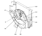
図4は、吸放湿手段119、放熱器103、吸熱器105、補助加熱部5部分のファン側から見た組立図であり、図5は、吸放湿手段119、放熱器103、吸熱器105、補助加熱部5部分のファン側から見た詳細展開図で、図6は吸放湿手段119、放熱器103、吸熱器105、パージ空気量調整手段9部分の吸込口側から見た詳細展開図である。   FIG. 4 is an assembly view of the moisture absorption / release means 119, the radiator 103, the heat absorber 105, and the auxiliary heating unit 5 viewed from the fan side, and FIG. 5 shows the moisture absorption / release means 119, the radiator 103, the heat absorber. 105 is a detailed development view seen from the fan side of the auxiliary heating unit 5 part, and FIG. 6 is a detail seen from the suction port side of the moisture absorbing / releasing means 119, the radiator 103, the heat absorber 105, and the purge air amount adjusting means 9 part. FIG.

吸放湿手段119は、吸着剤107が担持された軸方向に通風可能な円筒状のハニカムローター108を備えており、このハニカムローター108を回動自在に回転軸21で支持している。そして、ハニカムローター108の外周にギア22を形成し、このギア22と回転駆動する駆動モーター23の歯車部24をかみ合わせてハニカムローター108を回転する。この吸放湿手段119は、回転軸21を有するホルダー25とローターカバー26で挟み込まれて、ギア22にてシールする構成としている。また、ホルダー25とローターカバー26によって吸放湿手段119は除湿対象空気116に放湿する放湿部121と除湿対象空気116から吸湿する吸湿部120とパージ空気4から吸湿するパージ部27の3つの領域に分けられる。それぞれの領域を通過する空気は相互流通を抑制するように風路を仕切っており、特にパージ領域は放湿部121と吸湿部120間の直接の相互流通を抑制する機能も果たしている。   The moisture absorbing / releasing means 119 includes a cylindrical honeycomb rotor 108 which can carry air in the axial direction on which the adsorbent 107 is supported, and the honeycomb rotor 108 is rotatably supported by the rotating shaft 21. Then, the gear 22 is formed on the outer periphery of the honeycomb rotor 108, and the gear rotor 24 is rotated by meshing with the gear 22 of the drive motor 23 that is driven to rotate. The moisture absorbing / releasing means 119 is sandwiched between a holder 25 having a rotating shaft 21 and a rotor cover 26 and sealed by a gear 22. Further, the holder 25 and the rotor cover 26 allow the moisture absorbing / releasing means 119 to be a moisture releasing unit 121 that releases moisture to the dehumidifying target air 116, a moisture absorbing unit 120 that absorbs moisture from the dehumidifying target air 116, and a purge unit 27 that absorbs moisture from the purge air 4. Divided into two areas. Air passing through each region partitions the air path so as to suppress mutual circulation. In particular, the purge region also functions to suppress direct mutual circulation between the moisture release unit 121 and the moisture absorption unit 120.

駆動モーター23を駆動すると歯車部24を介してギア22に駆動力が伝達してハニカムローター108が回転することになる。このハニカムローター108の回転によって吸着剤107は、吸湿部120における除湿対象空気116との接触と放湿部121における除湿対象空気116とパージ部27におけるパージ空気4との接触を繰り返すことになる。この吸着剤107は、晒される空気の相対湿度が高ければ多くの水分を保持でき、相対湿度が低くなると保持可能な水分量が減少する特性を有しているので、相対湿度の異なる複数の空気との接触を繰り返せば、各々の相対湿度における吸着剤107の保持可能な水分量の差に応じて水分の吸脱着が行われることになる。ここで、吸湿部120で吸着剤107と接触する除湿対象空気116は、吸熱器105において冷媒117の吸熱により冷却された高い相対湿度の空気であり、放湿部121で吸着剤107と接触する除湿対象空気116は、放熱器103において冷媒117の放熱により加熱された低い相対湿度の空気、または放熱器103において冷媒117の放熱と補助加熱部5により加熱された空気であるので、この相対湿度の差によって、吸着剤107の吸脱着作用がなされて吸放湿手段119が作動することになるのである。また、吸湿部120で吸着剤107と接触するパージ空気4は、除湿装置周囲の空気であり、放湿部121に供給される除湿対象空気116より低温で吸湿部120に供給される除湿対象空気116より高温であるので、吸着剤107がパージ空気4によって予熱されてから放湿部121に移動して、放湿部121における除湿対象空気116への水分脱着量が増加することになる。すなわち、水分脱着量が増えるため、除湿ローターは保水可能量が増加するため、吸着部の水分量が増加することとなる。   When the drive motor 23 is driven, the driving force is transmitted to the gear 22 through the gear portion 24 and the honeycomb rotor 108 rotates. By the rotation of the honeycomb rotor 108, the adsorbent 107 repeats the contact with the dehumidification target air 116 in the moisture absorption unit 120 and the contact between the dehumidification target air 116 in the moisture release unit 121 and the purge air 4 in the purge unit 27. This adsorbent 107 has a characteristic that it can retain a large amount of moisture if the relative humidity of the exposed air is high, and the amount of water that can be retained decreases when the relative humidity is low. If the contact is repeated, moisture adsorption / desorption is performed according to the difference in the amount of moisture that can be held by the adsorbent 107 at each relative humidity. Here, the dehumidification target air 116 that comes into contact with the adsorbent 107 in the moisture absorption unit 120 is high relative humidity air that is cooled by the heat absorption of the refrigerant 117 in the heat absorber 105, and comes into contact with the adsorbent 107 in the moisture release unit 121. The dehumidification target air 116 is air having a low relative humidity heated by the heat radiation of the refrigerant 117 in the radiator 103 or air heated by the heat radiation of the refrigerant 117 and the auxiliary heating unit 5 in the heat radiator 103. Thus, the adsorption / desorption action of the adsorbent 107 is performed and the moisture absorption / release means 119 operates. Further, the purge air 4 that comes into contact with the adsorbent 107 in the hygroscopic unit 120 is air around the dehumidifying device, and is dehumidified target air supplied to the hygroscopic unit 120 at a lower temperature than the dehumidified target air 116 supplied to the moisture releasing unit 121. Since the temperature is higher than 116, the adsorbent 107 is preheated by the purge air 4 and then moves to the moisture release unit 121, and the moisture desorption amount to the dehumidification target air 116 in the moisture release unit 121 increases. That is, since the amount of moisture desorption increases, the amount of water that can be retained in the dehumidification rotor increases, and thus the amount of moisture in the adsorption portion increases.

ここで、図1の概略構成図で説明したそれぞれの空気の流れを図2、図5および図6を用いて説明する。ケース後15の吸込口112から本体101内に流入した空気は、放熱器103とパージ部27の二手に分かれる。パージ部27に向かうパージ空気4はホルダー25に設けられたパージ風路6を通り、パージ風路6に形成されたダンパー7によってパージ空気4量が調整される。ダンパー7が垂直になる場合は、パージ風路6が塞がれることになり、放熱器103を通過する風量が増加することになる。また、ダンパー7が水平になる場合はパージ空気4量が最大になる状態となり、ダンパー7が斜めになる場合はパージ空気4量を減らし、放熱器103を通過する風量が増加するように調整される。よってダンパー7を通過したパージ空気4は、ハニカムローター108のパージ部27を背面から通ってバイパス送風ファン2にて吹出口113から本体101外部に流出する。放熱器103を通過した空気は、バイパス送風ファン2に向かう加熱対象空気3と、放湿部121に向かう除湿対象空気116の二手に分かれる。加熱対象空気3はそのままバイパス送風ファン2にて吹出口113から本体101外部に流出する。除湿対象空気116は、補助加熱部5を通ってローターカバー26のガイドにより前面からハニカムローター108の放湿部121を通過し、ホルダー25の風路ガイドと吸熱器カバー20により吸熱器105の背面に導かれ、背面から吸熱器105、吸湿部120を通過して、ローターカバー26のガイドによりメイン送風ファン1にて吹出口113から本体101外部に流出する。   Here, the respective air flows described in the schematic configuration diagram of FIG. 1 will be described with reference to FIGS. 2, 5, and 6. The air that has flowed into the main body 101 from the suction port 112 after the case 15 is divided into the radiator 103 and the purge unit 27. The purge air 4 toward the purge unit 27 passes through the purge air passage 6 provided in the holder 25, and the amount of purge air 4 is adjusted by a damper 7 formed in the purge air passage 6. When the damper 7 is vertical, the purge air passage 6 is blocked, and the amount of air passing through the radiator 103 is increased. Further, when the damper 7 is horizontal, the amount of purge air 4 is maximized, and when the damper 7 is inclined, the amount of purge air 4 is decreased and the amount of air passing through the radiator 103 is adjusted. The Therefore, the purge air 4 that has passed through the damper 7 passes through the purge portion 27 of the honeycomb rotor 108 from the back surface and flows out of the main body 101 from the outlet 113 by the bypass blower fan 2. The air that has passed through the radiator 103 is divided into two types of air, that is, the heating target air 3 toward the bypass blower fan 2 and the dehumidifying target air 116 toward the moisture release unit 121. The heating target air 3 flows out of the main body 101 from the outlet 113 by the bypass blower fan 2 as it is. The dehumidifying target air 116 passes through the auxiliary heating unit 5 through the moisture releasing unit 121 of the honeycomb rotor 108 from the front surface by the guide of the rotor cover 26, and the back surface of the heat absorber 105 by the air path guide of the holder 25 and the heat absorber cover 20. Then, it passes through the heat absorber 105 and the moisture absorption part 120 from the back, and flows out of the main body 101 from the air outlet 113 by the main blower fan 1 by the guide of the rotor cover 26.

図6に示すように、メイン送風ファン1とバイパス送風ファン2は並列に構成され、ケーシング28とモーターサポート29はそれぞれ一体化している。このため、それぞれのファンモーター支持を独立して行わずに兼ねることができるので支持構造が簡単になり、また、組立てが容易になり、また、本体101を薄型化、小型化することができる。   As shown in FIG. 6, the main blower fan 1 and the bypass blower fan 2 are configured in parallel, and the casing 28 and the motor support 29 are integrated with each other. For this reason, since each fan motor can be supported independently, the support structure is simplified, the assembly is facilitated, and the main body 101 can be reduced in thickness and size.

次に除湿装置の動作を説明する。   Next, the operation of the dehumidifier will be described.

図7は、本発明の実施形態1にかかる除湿装置の冷媒117の状態変化を示すモリエル線図(圧力−エンタルピ線図)である。点A、点B、点C、点Dを矢符で結んだサイクルは、冷媒回路106内を循環する冷媒117の状態変化を示しており、冷媒117は圧縮機102において圧縮されることにより圧力とエンタルピが上昇して点Aから点Bの状態変化を行い、放熱器103において供給される除湿対象空気116および加熱対象空気2に対して放熱することによりエンタルピが減少して点Bから点Cの状態となる。次に膨張機構104において膨張して減圧することにより圧力が低下して点Cから点Dの状態変化を行い、吸熱器105において供給される除湿対象空気116から吸熱することによりエンタルピが増加して点Dから点Aの状態に戻る。このような冷媒117の状態変化により、吸熱器105において吸熱し、放熱器103において放熱するヒートポンプ118が動作し、この時、点Bと点Cのエンタルピ差に冷媒117の循環量を乗じた値が放熱器103における放熱量、点Aと点D(点C)のエンタルピ差に冷媒117の循環量を乗じた値が吸熱器105における吸熱量となり、放熱量と吸熱量の差、即ち点Bと点Aのエンタルピ差に冷媒117の循環量を乗じた値が圧縮機102の圧縮仕事量になる。   FIG. 7 is a Mollier diagram (pressure-enthalpy diagram) showing a state change of the refrigerant 117 of the dehumidifier according to Embodiment 1 of the present invention. A cycle obtained by connecting points A, B, C, and D with arrows indicates a change in the state of the refrigerant 117 circulating in the refrigerant circuit 106, and the refrigerant 117 is compressed by the compressor 102 so that the pressure is increased. The enthalpy rises to change the state from the point A to the point B, and radiates heat to the dehumidification target air 116 and the heating target air 2 supplied in the radiator 103, so that the enthalpy decreases and the point B to the point C It becomes the state of. Next, when the expansion mechanism 104 expands and depressurizes, the pressure decreases to change the state from point C to point D, and the enthalpy increases by absorbing heat from the dehumidification target air 116 supplied by the heat absorber 105. The state returns from the point D to the point A. Due to the state change of the refrigerant 117, the heat pump 118 that absorbs heat in the heat absorber 105 and radiates heat in the radiator 103 operates. At this time, a value obtained by multiplying the enthalpy difference between the points B and C by the circulation amount of the refrigerant 117 Is the heat dissipation amount in the radiator 103, and the value obtained by multiplying the enthalpy difference between the points A and D (point C) by the circulation amount of the refrigerant 117 is the heat absorption amount in the heat absorber 105, that is, the difference between the heat dissipation amount and the heat absorption amount, that is, the point B A value obtained by multiplying the enthalpy difference between the point A and the circulatory amount of the refrigerant 117 becomes the compression work amount of the compressor 102.

図8は、本発明の実施形態1にかかる除湿装置における除湿対象空気116、加熱対象空気3、パージ空気4の状態変化を示す湿り空気線図であり、各々の空気状態の変化を説明する。   FIG. 8 is a moist air diagram showing changes in the states of the dehumidification target air 116, the heating target air 3, and the purge air 4 in the dehumidification apparatus according to Embodiment 1 of the present invention, and the changes in the respective air states will be described.

まず、点aの状態の除湿対象空気116および加熱対象空気3が放熱器103に供給され、冷媒117の放熱により加熱されて点bの状態となる。ここで加熱対象空気3は、点bの状態のまま装置外部に排出され、除湿対象空気116は、放湿部121に供給されてハニカムローター108に担持された吸着剤107が保有している水分を脱着することにより加湿されて、湿度が上昇するとともに温度が低下して点cの状態となる。点cの状態となった除湿対象空気116は次に吸熱器105に供給され、冷媒117の吸熱により露点温度以下まで冷却されて点dの飽和状態となる。この時に飽和した水分は凝縮水としてタンク122に回収される。最後に除湿対象空気116は吸湿部120に供給され、吸着剤107に水分を吸着されることによって除湿され、湿度が低下するとともに温度が上昇して点eの状態の乾燥空気となり装置外部に排出される。   First, the dehumidification target air 116 and the heating target air 3 in the state of point a are supplied to the radiator 103 and heated by the heat dissipation of the refrigerant 117 to be in the state of point b. Here, the air to be heated 3 is discharged to the outside of the apparatus in the state of point b, and the air to be dehumidified 116 is supplied to the moisture release unit 121 and is held in the adsorbent 107 carried on the honeycomb rotor 108. As the humidity increases, the temperature decreases and the point c is reached. The dehumidifying target air 116 that has reached the state of point c is then supplied to the heat absorber 105 and is cooled to the dew point temperature or lower by the heat absorption of the refrigerant 117 and becomes saturated at point d. The water saturated at this time is collected in the tank 122 as condensed water. Finally, the air to be dehumidified 116 is supplied to the moisture absorption unit 120 and dehumidified by adsorbing moisture to the adsorbent 107. The humidity decreases and the temperature rises to become dry air in the state of point e and is discharged outside the apparatus. Is done.

一方、点aの状態のパージ空気4は、吸湿部120に供給されて吸着剤107がパージ空気4によって予熱されるとともに吸着剤107に水分を吸着されることによって除湿され、温度が上昇するとともに湿度が低下して点fの乾燥空気となる。点bの状態となった加熱対象空気3と点fの状態となったパージ空気4は、ともにバイパス送風ファン2に吸引されて装置外部に排出される。   On the other hand, the purge air 4 in the state of the point a is supplied to the moisture absorption unit 120 and the adsorbent 107 is preheated by the purge air 4 and dehumidified by adsorbing moisture to the adsorbent 107, and the temperature rises. The humidity is reduced to dry air at point f. The heating target air 3 in the state of point b and the purge air 4 in the state of point f are both sucked into the bypass blower fan 2 and discharged outside the apparatus.

以上の除湿対象空気116およびパージ空気4の状態変化において、吸熱器105において回収される凝縮水の量は、点cと点dの絶対湿度差に除湿対象空気116の重量換算風量を乗じた値となり、放湿部121における放湿量は、点bと点cの絶対湿度差に除湿対象空気116の重量換算風量を乗じた値となる。また、吸湿部120における吸湿量は、点dと点eの絶対湿度差に除湿対象空気116の重量換算風量を乗じた値と点aと点fの絶対湿度差にパージ空気4の重量換算風量を乗じた値との加算値となる。   In the state change of the dehumidification target air 116 and the purge air 4 described above, the amount of condensed water recovered in the heat absorber 105 is a value obtained by multiplying the absolute humidity difference between the points c and d by the weight-converted air volume of the dehumidification target air 116. Thus, the moisture release amount in the moisture release portion 121 is a value obtained by multiplying the absolute humidity difference between the points b and c by the weight-converted air volume of the dehumidifying target air 116. Further, the moisture absorption amount in the moisture absorption unit 120 is obtained by multiplying the absolute humidity difference between the points d and e by the weight-converted air volume of the air to be dehumidified 116 and the absolute humidity difference between the points a and f and the weight-converted air volume of the purge air 4. It is an added value with the value multiplied by.

以上の動作において、理想状態では、放湿部121の出口空気状態を示す点cは、吸湿部120の入口空気状態を示す点dと同一の相対湿度である点c’に近づき、吸湿部120の出口空気状態を示す点eは、放湿部121の入口空気状態を示す点bと同一の相対湿度である点e’に近づく。したがって点dの相対湿度を上昇させ、点bの相対湿度を低下させること、即ち、点dで示した吸湿部120への供給空気と点bで示した放湿部121への供給空気との相対湿度差を拡大することが吸放湿量を高めることになり、結果的に除湿効率が向上することになる。また、除湿対象空気116の重量換算風量と加熱対象空気3の重量換算風量を加算して点aと点bのエンタルピ差に乗じた値が放熱器103における放熱量、点cと点dのエンタルピ差に除湿対象空気116の重量換算風量を乗じた値が吸熱器105における吸熱量となり、この放熱器103における放熱量および吸熱器105における吸熱量は、図2の冷媒117の状態変化から得られる放熱量および吸熱量と等しくなる。従って、放熱器103において除湿対象空気116のみでは不足する冷媒117の放熱分を加熱対象空気3が補うことにより、除湿対象空気116の風量を放湿部121における放湿、吸熱器105における冷却、吸湿部120における吸湿の過程における最適な値に設定することができるのである。また、各点a、b、c、d、e、fが風路的に隣り合い互いの風路間の漏れに対し、除湿効率が低下する。   In the above operation, in the ideal state, the point c indicating the outlet air state of the moisture releasing unit 121 approaches the point c ′ having the same relative humidity as the point d indicating the inlet air state of the moisture absorbing unit 120, and the moisture absorbing unit 120. The point e that indicates the outlet air state of the water is close to the point e ′ that has the same relative humidity as the point b that indicates the inlet air state of the moisture releasing unit 121. Therefore, the relative humidity at the point d is increased and the relative humidity at the point b is decreased, that is, the supply air to the moisture absorption unit 120 indicated by the point d and the supply air to the moisture release unit 121 indicated by the point b. Enlarging the relative humidity difference increases the amount of moisture absorbed and released, resulting in improved dehumidification efficiency. Further, the value obtained by adding the weight-converted air volume of the dehumidifying target air 116 and the weight-converted air volume of the heating target air 3 and multiplying by the enthalpy difference between the points a and b is the heat dissipation amount in the radiator 103, and the enthalpy of the points c and d. A value obtained by multiplying the difference by the weight-converted air volume of the air to be dehumidified 116 becomes the heat absorption amount in the heat absorber 105, and the heat radiation amount in the heat radiator 103 and the heat absorption amount in the heat absorber 105 are obtained from the state change of the refrigerant 117 in FIG. It becomes equal to heat dissipation and heat absorption. Accordingly, the heating target air 3 compensates for the heat radiation of the refrigerant 117 that is insufficient with only the dehumidifying target air 116 in the radiator 103, so that the air volume of the dehumidifying target air 116 is dehumidified in the dehumidifying section 121, cooled in the heat absorber 105, It is possible to set the optimum value in the process of moisture absorption in the moisture absorption unit 120. In addition, the points a, b, c, d, e, and f are adjacent to each other in the air path, and the dehumidification efficiency is reduced with respect to leakage between the air paths.

以上、説明した構成および動作により、本実施形態の除湿装置は基本的に以下の効果を奏するものである。   As described above, with the configuration and operation described above, the dehumidifying device of the present embodiment basically has the following effects.

除湿対象空気116を、放熱器103においてヒートポンプ118の放熱により加熱し、次に放湿部121において吸放湿手段119の放湿により加湿し、次に吸熱器105においてヒートポンプ118の吸熱により冷却し、次に吸湿部120において吸放湿手段119の吸湿により除湿することによって、吸湿部120に供給される除湿対象空気116と放湿部121に供給される除湿対象空気116との相対湿度差を拡大し、循環経路111を設けない単純な構成で吸放湿手段119の吸放湿量を増加することができる。さらに放熱器103に加熱対象空気3を供給することによって、ヒートポンプ118の放熱に適する風量と、吸放湿手段119の吸放湿およびヒートポンプ118の吸熱に適する風量とのアンバランスを解消し、効率の良い除湿を行うことができる。さらにパージ空気4によって吸着剤107が予熱されてから放湿部121に移動するので、吸湿部120における除湿対象空気116からの水分吸着量が増加するとともに、放湿部121における除湿対象空気116への水分脱着量が増加することになるように調節することができる。   The air to be dehumidified 116 is heated by the heat dissipation of the heat pump 118 in the radiator 103, then humidified by the moisture absorption / release means 119 in the moisture release unit 121, and then cooled by the heat absorption of the heat pump 118 in the heat absorber 105. Next, by dehumidifying the moisture absorbing section 120 by absorbing moisture by the moisture absorbing / releasing means 119, the relative humidity difference between the dehumidifying target air 116 supplied to the moisture absorbing section 120 and the dehumidifying target air 116 supplied to the moisture releasing section 121 is determined. The moisture absorption / release amount of the moisture absorption / release means 119 can be increased with a simple configuration that does not provide the circulation path 111. Furthermore, by supplying the air 3 to be heated to the radiator 103, the imbalance between the air volume suitable for heat dissipation of the heat pump 118 and the air volume suitable for moisture absorption / release of the moisture absorption / release means 119 and heat absorption of the heat pump 118 is eliminated, and the efficiency Good dehumidification can be performed. Further, since the adsorbent 107 is preheated by the purge air 4 and moves to the moisture release unit 121, the amount of moisture adsorbed from the dehumidification target air 116 in the moisture absorption unit 120 increases and also to the dehumidification target air 116 in the moisture release unit 121. It is possible to adjust so that the amount of water desorbed increases.

次に個別のケースについて説明する。   Next, individual cases will be described.

パージ空気量調整手段9を室温検知手段30の出力に応じて制御する構成とした場合には、室温が35℃以上では、圧縮機102の使用温度範囲を超えるような過負荷条件では、放熱器103の通風を最大にするようにダンパー7を閉にして運転することにより、放熱器103の温度が低下して圧縮機102の使用温度範囲に入ることになり、連続して運転が可能となる。また室温が低い場合(15℃以下)には、ダンパー7を全開にして、パージ空気4量を最大にして、吸着剤107に予熱を与えてから放湿部121に移動するので、吸湿部120における除湿対象空気116からの水分吸着量が増加するとともに、放湿部121における除湿対象空気116への水分脱着量が増加することができる。また、室温が中間の場合(15℃〜35℃)には、ダンパー7を半開にして、吸着剤107に予熱を与えて、かつ圧縮機102の使用温度範囲に入れるような放熱器103の温度を上昇させて放湿部温度を最大にして、吸湿部120における除湿対象空気116からの水分吸着量が増加するとともに、放湿部121における除湿対象空気116への水分脱着量が増加するようにして除湿量を最大にすることが可能となる。   When the purge air amount adjusting means 9 is controlled in accordance with the output of the room temperature detecting means 30, the radiator is used under an overload condition that exceeds the operating temperature range of the compressor 102 when the room temperature is 35 ° C. or higher. By operating with the damper 7 closed so as to maximize the ventilation of the air 103, the temperature of the radiator 103 falls and enters the operating temperature range of the compressor 102, and the operation can be continuously performed. . When the room temperature is low (15 ° C. or lower), the damper 7 is fully opened, the amount of purge air 4 is maximized, the adsorbent 107 is preheated, and then moves to the moisture releasing unit 121. As the amount of moisture adsorbed from the dehumidifying target air 116 increases, the amount of moisture desorbed to the dehumidifying target air 116 in the moisture release section 121 can increase. Further, when the room temperature is intermediate (15 ° C. to 35 ° C.), the temperature of the radiator 103 is such that the damper 7 is half-opened to preheat the adsorbent 107 and enter the operating temperature range of the compressor 102. Is increased so that the moisture release unit temperature is maximized so that the moisture adsorption amount from the dehumidification target air 116 in the moisture absorption unit 120 increases and the moisture desorption amount to the dehumidification target air 116 in the moisture release unit 121 increases. This makes it possible to maximize the amount of dehumidification.

また、パージ空気量調整手段9を放湿部周辺温度検知手段31の出力に応じて制御する構成とした場合には、放熱部周辺温度が90℃以上では、樹脂耐熱温度を超えるような運転条件であるという場合は、放熱器103の通風を最大にするようにダンパー7を閉にして運転することにより、放熱器周辺の温度が低下して樹脂耐熱温度に入ることになり連続して運転が可能となる。放湿部周辺温度が低い場合(50℃以下)には、ダンパー7を全開にして、パージ空気4量を最大にして、吸着剤107に予熱を与えてから放湿部121に移動するので、吸湿部120における除湿対象空気116からの水分吸着量が増加するとともに、放湿部121における除湿対象空気116への水分脱着量が増加することができる。また、放湿部周辺温度が中間の場合(50℃〜90℃)には、ダンパー7を半開にして、吸着剤107に予熱を与えて、かつ樹脂耐熱温度範囲に入れるような放湿部周辺温度まで上昇させて放湿部温度を最大にして、吸湿部120における除湿対象空気116からの水分吸着量が増加するとともに、放湿部121における除湿対象空気116への水分脱着量が増加するようにして除湿量を最大にすることが可能となる。   Further, when the purge air amount adjusting means 9 is controlled in accordance with the output of the moisture release portion ambient temperature detection means 31, the operating conditions are such that the heat radiation portion ambient temperature exceeds the resin heat resistance temperature at 90 ° C. or higher. In that case, by operating with the damper 7 closed so as to maximize the ventilation of the radiator 103, the temperature around the radiator decreases to enter the resin heat resistance temperature, and the operation continues. It becomes possible. When the ambient temperature of the moisture release section is low (50 ° C. or lower), the damper 7 is fully opened, the purge air 4 amount is maximized, and the adsorbent 107 is preheated before moving to the moisture release section 121. The moisture adsorption amount from the dehumidification target air 116 in the moisture absorption unit 120 can be increased, and the moisture desorption amount to the dehumidification target air 116 in the moisture release unit 121 can be increased. Further, when the ambient temperature of the moisture release portion is intermediate (50 ° C. to 90 ° C.), the damper 7 is opened halfway, preheating the adsorbent 107 and entering the resin heat resistant temperature range. The temperature is increased to the maximum temperature of the moisture release unit, so that the amount of moisture adsorbed from the dehumidification target air 116 in the moisture absorption unit 120 increases and the amount of moisture desorption to the dehumidification target air 116 in the moisture release unit 121 increases. Thus, the dehumidification amount can be maximized.

また、パージ空気量調整手段9を補助加熱部周辺温度検知手段32の出力に応じて制御する構成とした場合には、補助加熱部周辺温度が180℃以上では、樹脂耐熱温度を超えるような運転条件であるという相関関係があり、その場合に、放熱器103の通風を最大にするようにダンパー7を閉にして運転することにより、補助加熱部周辺の温度が低下して樹脂耐熱温度に入ることになり、連続して運転が可能となる。補助加熱部周辺温度が低い場合(70℃以下)には、ダンパー7を全開にして、パージ空気4量を最大にして、吸着剤107に予熱を与えてから放湿部121に移動するので、吸湿部120における除湿対象空気116からの水分吸着量が増加するとともに、放湿部121における除湿対象空気116への水分脱着量が増加することができる。また、補助加熱部周辺温度が中間の場合(70℃〜180℃)には、ダンパー7を半開にして、吸着剤107に予熱を与えて、かつ樹脂耐熱温度範囲に入れるような補助加熱部周辺温度まで上昇させて放湿部温度を最大にして、吸湿部120における除湿対象空気116からの水分吸着量が増加するとともに、放湿部121における除湿対象空気116への水分脱着量が増加するようにして除湿量を最大にすることが可能となる。   Further, when the purge air amount adjusting means 9 is configured to be controlled according to the output of the auxiliary heating part ambient temperature detection means 32, an operation that exceeds the resin heat resistance temperature when the auxiliary heating part ambient temperature is 180 ° C. or higher. In this case, by operating with the damper 7 closed so as to maximize the ventilation of the radiator 103, the temperature around the auxiliary heating unit is lowered and the resin heat resistance temperature is entered. As a result, continuous operation is possible. When the auxiliary heating unit ambient temperature is low (70 ° C. or less), the damper 7 is fully opened, the purge air 4 amount is maximized, the adsorbent 107 is preheated, and then moved to the moisture release unit 121. The moisture adsorption amount from the dehumidification target air 116 in the moisture absorption unit 120 can be increased, and the moisture desorption amount to the dehumidification target air 116 in the moisture release unit 121 can be increased. Further, when the temperature around the auxiliary heating unit is intermediate (70 ° C. to 180 ° C.), the damper 7 is opened halfway to preheat the adsorbent 107 and enter the resin heat resistant temperature range. The temperature is increased to the maximum temperature of the moisture release unit, so that the amount of moisture adsorbed from the dehumidification target air 116 in the moisture absorption unit 120 increases and the amount of moisture desorption to the dehumidification target air 116 in the moisture release unit 121 increases. Thus, the dehumidification amount can be maximized.

また、パージ空気量調整手段9を補助加熱部5の加熱量に応じて制御する構成とした場合では、補助加熱部5の出力が最大の場合(300W)には、補助加熱部5の温度が最大になるため、ダンパー7を全開にして、吸湿部120における除湿対象空気116からの水分吸着量を増加させるとともに放湿部121における除湿対象空気116への水分脱着量が増加することができる。補助加熱部5の出力が中間の場合(200W)には、補助加熱部5の温度が下がるので、ダンパー7を半開にして、パージ空気4により、吸着剤107に予熱を与えてから放湿部121に移動するので、補助加熱部周辺の温度が上昇し、放湿部121における除湿対象空気116への水分脱着量が増加するとともに、吸湿部120における除湿対象空気116からの水分吸着量が増加することができる。また、補助加熱部5の出力が最小の場合(100W)には、ダンパー7を全閉にして、吸着剤107に予熱を与えて補助加熱部周辺温度を上昇させて放湿部温度を最大にして、吸湿部120における除湿対象空気116からの水分吸着量が増加するとともに、放湿部121における除湿対象空気116への水分脱着量が増加するようにして除湿量を最大にすることが可能となる。   In the case where the purge air amount adjusting means 9 is controlled according to the heating amount of the auxiliary heating unit 5, when the output of the auxiliary heating unit 5 is maximum (300 W), the temperature of the auxiliary heating unit 5 is Therefore, the damper 7 is fully opened to increase the amount of moisture adsorbed from the dehumidification target air 116 in the moisture absorption unit 120 and to increase the amount of moisture desorption from the dehumidification target air 116 in the moisture release unit 121. When the output of the auxiliary heating unit 5 is intermediate (200 W), the temperature of the auxiliary heating unit 5 is lowered. Therefore, the damper 7 is half-opened and the adsorbent 107 is preheated by the purge air 4 and then the moisture releasing unit. 121, the temperature around the auxiliary heating unit rises, the amount of moisture desorbed to the dehumidification target air 116 in the moisture release unit 121 increases, and the amount of moisture adsorption from the dehumidification target air 116 in the moisture absorption unit 120 increases. can do. Further, when the output of the auxiliary heating unit 5 is minimum (100 W), the damper 7 is fully closed to preheat the adsorbent 107 to increase the temperature around the auxiliary heating unit to maximize the moisture release unit temperature. Thus, the moisture adsorption amount from the dehumidification target air 116 in the moisture absorption unit 120 increases, and the moisture desorption amount to the dehumidification target air 116 in the moisture release unit 121 increases so that the dehumidification amount can be maximized. Become.

このことにより、補助加熱部5による放湿部121における除湿対象空気116への水分脱着量が増加させつつ、吸湿部120における除湿対象空気116での水分吸着量が増加をさせることが可能であり、かつ補助加熱部5の出力を低下させても、補助加熱部周辺の温度を最大にするように調整し、効率的な運転に調整することが可能となるものである。   Accordingly, it is possible to increase the amount of moisture adsorbed in the dehumidifying target air 116 in the moisture absorbing unit 120 while increasing the amount of moisture desorbed to the dehumidifying target air 116 in the moisture releasing unit 121 by the auxiliary heating unit 5. In addition, even if the output of the auxiliary heating unit 5 is reduced, the temperature around the auxiliary heating unit can be adjusted to the maximum so that the operation can be adjusted efficiently.

また、パージ空気量調整手段9を室温検知手段30と放湿部周辺温度検知手段31の出力に応じて制御する構成とした場合では、室温が35℃以上では、圧縮機102の使用温度範囲を超えるような過負荷条件と、放熱部周辺温度が90℃以上では、樹脂耐熱温度を超えるような運転条件であるという場合のどちらか高い温度を検知して、放熱器103の通風を最大にするようにダンパー7を閉にして運転することにより、放熱器103の温度が低下して圧縮機102の使用温度範囲に入り、かつ樹脂耐熱温度に入ることになり連続して運転が可能となる。また室温が低い場合(15℃以下)には、ダンパー7を全開にして、パージ空気4量を最大にして、吸着剤107に予熱を与えてから放湿部121に移動するので、吸湿部120における除湿対象空気116からの水分吸着量が増加するとともに、放湿部121における除湿対象空気116への水分脱着量が増加することができる。また、室温が中間の場合(15℃〜35℃)には、ダンパー7を半開にして、吸着剤107に予熱を与えて、かつ圧縮機102の使用温度範囲に入れ、かつ樹脂耐熱温度に入るような放熱器103の温度まで上昇させて放湿部温度を最大にして、吸湿部120における除湿対象空気116からの水分吸着量が増加するとともに、放湿部121における除湿対象空気116への水分脱着量が増加するようにして除湿量をより最大にすることが可能となる。   Further, in the case where the purge air amount adjusting means 9 is controlled according to the outputs of the room temperature detecting means 30 and the moisture release portion ambient temperature detecting means 31, the operating temperature range of the compressor 102 is set at a room temperature of 35 ° C. or higher. If the overload condition exceeds 100 ° C and the ambient temperature of the heat dissipating part is 90 ° C or higher, the higher temperature of the operating condition that exceeds the resin heat resistance temperature is detected, and the ventilation of the radiator 103 is maximized. By operating with the damper 7 closed as described above, the temperature of the radiator 103 is lowered to enter the operating temperature range of the compressor 102 and to the resin heat resistance temperature, and continuous operation is possible. When the room temperature is low (15 ° C. or lower), the damper 7 is fully opened, the amount of purge air 4 is maximized, the adsorbent 107 is preheated, and then moves to the moisture releasing unit 121. As the amount of moisture adsorbed from the dehumidifying target air 116 increases, the amount of moisture desorbed to the dehumidifying target air 116 in the moisture release section 121 can increase. Further, when the room temperature is intermediate (15 ° C. to 35 ° C.), the damper 7 is half-opened to preheat the adsorbent 107 and enter the operating temperature range of the compressor 102 and enter the resin heat resistance temperature. The temperature of the radiator 103 is increased to maximize the moisture releasing section temperature, the amount of moisture adsorbed from the dehumidifying target air 116 in the moisture absorbing section 120 is increased, and the moisture to the dehumidifying target air 116 in the moisture releasing section 121 is increased. It is possible to maximize the dehumidification amount by increasing the desorption amount.

また、パージ空気量調整手段9を室温検知手段30と補助加熱部周辺温度検知手段32の出力に応じて制御する構成とした場合には、室温が35℃以上では、圧縮機102の使用温度範囲を超えるような過負荷条件と、補助加熱部周辺温度が180℃以上では、樹脂耐熱温度を超えるような運転条件であるという相関関係があり、樹脂耐熱温度を超えるような運転条件であるという場合のどちらか高い温度を検知して、放熱器103の通風を最大にするようにダンパー7を閉にして運転することにより、放熱器103の温度が低下して圧縮機102の使用温度範囲に入り、かつ樹脂耐熱温度に入ることになり連続して運転が可能となる。また室温が低い場合(15℃以下)には、ダンパー7を全開にして、パージ空気4量を最大にして、吸着剤107に予熱を与えてから放湿部121に移動するので、吸湿部120における除湿対象空気116からの水分吸着量が増加するとともに、放湿部121における除湿対象空気116への水分脱着量が増加することができる。また、室温が中間の場合(15℃〜35℃)には、ダンパー7を半開にして、吸着剤107に予熱を与えて、かつ圧縮機102の使用温度範囲に入れ、かつ樹脂耐熱温度に入るような放熱器103の温度まで上昇させて放湿部温度を最大にして、吸湿部120における除湿対象空気116からの水分吸着量が増加するとともに、放湿部121における除湿対象空気116への水分脱着量が増加するようにして除湿量をより最大にすることが可能となる。   When the purge air amount adjusting means 9 is controlled according to the outputs of the room temperature detecting means 30 and the auxiliary heating portion ambient temperature detecting means 32, the operating temperature range of the compressor 102 is used when the room temperature is 35 ° C. or higher. When there is an overload condition that exceeds the heat resistance temperature and the auxiliary heating part ambient temperature is 180 ° C. or more, there is a correlation that the operation condition is such that the resin heat resistance temperature is exceeded. By detecting the higher temperature and operating the damper 7 closed so as to maximize the ventilation of the radiator 103, the temperature of the radiator 103 decreases and enters the operating temperature range of the compressor 102. In addition, the resin heat resistance temperature is entered, and continuous operation becomes possible. When the room temperature is low (15 ° C. or lower), the damper 7 is fully opened, the amount of purge air 4 is maximized, the adsorbent 107 is preheated, and then moves to the moisture releasing unit 121. As the amount of moisture adsorbed from the dehumidifying target air 116 increases, the amount of moisture desorbed to the dehumidifying target air 116 in the moisture release section 121 can increase. Further, when the room temperature is intermediate (15 ° C. to 35 ° C.), the damper 7 is half-opened to preheat the adsorbent 107 and enter the operating temperature range of the compressor 102 and enter the resin heat resistance temperature. The temperature of the radiator 103 is increased to maximize the moisture releasing section temperature, the amount of moisture adsorbed from the dehumidifying target air 116 in the moisture absorbing section 120 is increased, and the moisture to the dehumidifying target air 116 in the moisture releasing section 121 is increased. It is possible to maximize the dehumidification amount by increasing the desorption amount.

また、パージ空気量調整手段9を室温検知手段30と補助加熱部5の出力に応じて制御する構成とした場合には、室温が35℃以上では、圧縮機102の使用温度範囲を超えるような過負荷条件と補助加熱部6の出力が大では、放熱器103の通風を最大にするようにダンパー7を閉にして運転することにより、放熱器103の温度が低下して圧縮機102の使用温度範囲に入ることになり連続して運転が可能となる。また室温が低い場合(15℃以下)に、補助加熱部5の出力が大の場合(300W)は、ダンパー7を全開にして、パージ空気4量を最大にして、吸着剤107に予熱を与えてから放湿部121に移動するので、吸湿部120における除湿対象空気116からの水分吸着量が増加するとともに、放湿部121における除湿対象空気116への水分脱着量が増加することができる。また、室温が中間の場合(15℃〜35℃)には、補助加熱部5の出力が大の時(300W)には、ダンパー7を半開にして、吸着剤107に予熱を与えて、かつ圧縮機102の使用温度範囲に入れるような放熱器103の温度まで上昇させて放湿部温度を最大にして、吸湿部120における除湿対象空気116からの水分吸着量が増加するとともに、放湿部121における除湿対象空気116への水分脱着量が増加するようにして除湿量をより最大にすることが可能となる。そこで、補助加熱部5が中の場合(200W)、または補助加熱部5が小の場合(100W)には、室温検知することにより、圧縮機102の使用温度範囲の最大まで、ダンパー7開度を開にして加熱部周辺温度を上昇させる様にすることにより、放湿温度を上昇させて調整することにより、より効率的に運転をおこなうことが可能である。   Further, when the purge air amount adjusting means 9 is controlled according to the outputs of the room temperature detecting means 30 and the auxiliary heating unit 5, the operating temperature range of the compressor 102 is exceeded when the room temperature is 35 ° C. or higher. When the overload condition and the output of the auxiliary heating unit 6 are large, the operation of the compressor 102 is performed by lowering the temperature of the radiator 103 by operating with the damper 7 closed so as to maximize the ventilation of the radiator 103. Entering the temperature range allows continuous operation. When the room temperature is low (15 ° C. or lower) and the output of the auxiliary heating unit 5 is large (300 W), the damper 7 is fully opened, the amount of purge air 4 is maximized, and the adsorbent 107 is preheated. Therefore, the moisture adsorption amount from the dehumidification target air 116 in the moisture absorption unit 120 increases, and the moisture desorption amount to the dehumidification target air 116 in the moisture release unit 121 can increase. When the room temperature is intermediate (15 ° C. to 35 ° C.), when the output of the auxiliary heating unit 5 is large (300 W), the damper 7 is opened halfway to preheat the adsorbent 107, and The temperature of the radiator 103 that is within the operating temperature range of the compressor 102 is increased to maximize the moisture release temperature, and the moisture adsorption amount from the dehumidification target air 116 in the moisture absorption part 120 increases, and the moisture release part It is possible to maximize the dehumidification amount by increasing the amount of moisture desorbed to the dehumidification target air 116 at 121. Therefore, when the auxiliary heating unit 5 is in the middle (200 W), or when the auxiliary heating unit 5 is small (100 W), the damper 7 opening degree is detected up to the maximum operating temperature range of the compressor 102 by detecting the room temperature. By opening and increasing the temperature around the heating unit, it is possible to operate more efficiently by increasing and adjusting the moisture release temperature.

また、パージ空気量調整手段9を放湿部周辺温度検知手段31と補助加熱部周辺温度検知手段32の出力に応じて制御する構成とした場合は、放湿部周辺温度が90℃以上の場合と、補助加熱部周辺温度が180℃以上では、樹脂耐熱温度を超えるような運転条件であるという相関関係があり、樹脂耐熱温度を超えるような運転条件であるという場合のどちらか高い温度を検知して、放熱器103の通風を最大にするようにダンパー7を閉にして運転することにより、放熱器103の温度が低下して樹脂耐熱温度に入ることになり連続して運転が可能となる。また放湿部周辺温度が50℃以下の場合かつ補助加熱部周辺温度が120℃以下である両周辺部温度が低い場合には、ダンパー7を全開にして、パージ空気4量を最大にして、吸着剤107に予熱を与えてから放湿部121に移動するので、吸湿部120における除湿対象空気116からの水分吸着量が増加するとともに、放湿部121における除湿対象空気116への水分脱着量が増加することができる。また、放湿部周辺温度が50℃〜90℃の場合または補助加熱部周辺温度が120〜180℃の場合の各周辺温度が中間の場合には、ダンパー7を半開にして、吸着剤107に予熱を与えて、かつ圧縮機102の使用温度範囲に入れ、かつ樹脂耐熱温度に入るような放熱器103の温度まで上昇させて放湿部温度を最大にして、吸湿部120における除湿対象空気116からの水分吸着量が増加するとともに、放湿部121における除湿対象空気116への水分脱着量が増加するようにして除湿量をより最大にすることが可能となる。   Further, when the purge air amount adjusting means 9 is controlled in accordance with the outputs of the moisture release part ambient temperature detection means 31 and the auxiliary heating part ambient temperature detection means 32, the moisture release part ambient temperature is 90 ° C. or more. When the ambient temperature of the auxiliary heating section is 180 ° C or higher, there is a correlation that the operating condition exceeds the resin heat resistance temperature, and the higher temperature is detected when the operation condition exceeds the resin heat resistance temperature. Then, by operating with the damper 7 closed so as to maximize the ventilation of the radiator 103, the temperature of the radiator 103 falls and enters the resin heat resistance temperature, and the operation can be continuously performed. . When the ambient temperature of the moisture release part is 50 ° C. or less and the temperature of both peripheral parts is 120 ° C. or less, the damper 7 is fully opened and the amount of purge air 4 is maximized, Since the adsorbent 107 is preheated and moves to the moisture release unit 121, the amount of moisture adsorbed from the dehumidification target air 116 in the moisture absorption unit 120 increases and the moisture desorption amount to the dehumidification target air 116 in the moisture release unit 121. Can be increased. Further, when the ambient temperature is 50 to 90 ° C. or each ambient temperature is intermediate when the auxiliary heating unit ambient temperature is 120 to 180 ° C., the damper 7 is half-opened to the adsorbent 107. Air to be dehumidified 116 in the hygroscopic section 120 is obtained by preheating, increasing the temperature of the radiator 103 so as to be within the operating temperature range of the compressor 102 and entering the resin heat resistance temperature, and maximizing the moisture discharge section temperature. As the moisture adsorption amount increases, the moisture desorption amount to the dehumidification target air 116 in the moisture release unit 121 increases, so that the dehumidification amount can be maximized.

また、パージ空気量調整手段9を室温検知手段30と放湿部周辺温度検知手段31と補助加熱部周辺温度検知手段32の出力に応じて制御する構成とした場合は、室温が35℃以上では、圧縮機102の使用温度範囲を超えるような過負荷条件と、放湿部周辺温度が90℃以上の場合と、補助加熱部周辺温度が180℃以上では、樹脂耐熱温度を超えるような運転条件であるという相関関係があり、樹脂耐熱温度を超えるような運転条件であるという場合のどちらか高い温度を検知して、放熱器103の通風を最大にするようにダンパー7を閉にして運転することにより、放熱器103の温度が低下して、樹脂耐熱温度に入ることになりかつ圧縮機102の使用温度範囲に入ることになり連続運転が可能となる。また室温が低い場合(15℃以下)には、ダンパー7を全開にして、パージ空気4量を最大にして、吸着剤107に予熱を与えてから放湿部121に移動するので、吸湿部120における除湿対象空気116からの水分吸着量が増加するとともに、放湿部121における除湿対象空気116への水分脱着量が増加することができる。また、室温が中間の場合(15℃〜35℃)には、ダンパー7を半開にして、吸着剤107に予熱を与えて、かつ圧縮機102の使用温度範囲に入れ、かつ樹脂耐熱温度に入るような放熱器103の温度まで上昇させて放湿部温度を最大にして、吸湿部120における除湿対象空気116からの水分吸着量が増加するとともに、放湿部121における除湿対象空気116への水分脱着量が増加するようにして除湿量をより最大にすることが可能となる。   Further, when the purge air amount adjusting means 9 is controlled in accordance with the outputs of the room temperature detecting means 30, the moisture releasing section ambient temperature detecting means 31 and the auxiliary heating section ambient temperature detecting means 32, the room temperature is 35 ° C. or higher. Overload conditions that exceed the operating temperature range of the compressor 102, operating conditions that exceed the heat resistance temperature of the resin when the ambient temperature of the moisture release unit is 90 ° C or higher, and when the ambient temperature of the auxiliary heating unit is 180 ° C or higher When the operating condition is such that the resin heat resistance temperature is exceeded, the higher temperature is detected, and the damper 7 is closed to operate to maximize the ventilation of the radiator 103. As a result, the temperature of the radiator 103 is lowered, the resin heat resistance temperature is entered, and the operating temperature range of the compressor 102 is entered, so that continuous operation is possible. When the room temperature is low (15 ° C. or lower), the damper 7 is fully opened, the amount of purge air 4 is maximized, the adsorbent 107 is preheated, and then moves to the moisture releasing unit 121. As the amount of moisture adsorbed from the dehumidifying target air 116 increases, the amount of moisture desorbed to the dehumidifying target air 116 in the moisture release section 121 can increase. Further, when the room temperature is intermediate (15 ° C. to 35 ° C.), the damper 7 is half-opened to preheat the adsorbent 107 and enter the operating temperature range of the compressor 102 and enter the resin heat resistance temperature. The temperature of the radiator 103 is increased to maximize the moisture releasing section temperature, the amount of moisture adsorbed from the dehumidifying target air 116 in the moisture absorbing section 120 is increased, and the moisture to the dehumidifying target air 116 in the moisture releasing section 121 is increased. It is possible to maximize the dehumidification amount by increasing the desorption amount.

また、パージ空気量調整手段9を室温検知手段30と放湿部周辺温度検知手段31と補助加熱部周辺温度検知手段32の出力と補助加熱部5の加熱量に応じて制御する構成にした場合には、室温が35℃以上では、圧縮機102の使用温度範囲を超えるような過負荷条件と、放湿部周辺温度が90℃以上の場合と、補助加熱部周辺温度が180℃以上では、樹脂耐熱温度を超えるような運転条件であるという相関関係がる。樹脂耐熱温度を超えるような運転条件の場合で補助加熱部5の出力が大(300W)のときは、放熱器103の通風を最大にするようにダンパー7を閉にして運転することにより、放熱器103の温度が低下して圧縮機102の使用温度範囲に入ることになり、かつ樹脂耐熱温度に入ることになり、連続して運転が可能となる。また室温が低い場合(15℃以下)に、放湿部周辺温度と補助加熱部周辺温度を検知して、樹脂耐熱温度以下の場合に、補助加熱部5の出力が大(300W)のときは、ダンパー7を全開にして、パージ空気4量を最大にして、吸着剤107に予熱を与えてから放湿部121に移動するので、吸湿部120における除湿対象空気116からの水分吸着量が増加するとともに、放湿部121における除湿対象空気116への水分脱着量が増加することができる。また、室温が中間の場合(15℃〜35℃)には、放湿部周辺温度と補助加熱部周辺温度を検知して、樹脂耐熱温度が上昇した場合で補助加熱部5の出力が大(300W)のときには、ダンパー7を半開にして、吸着剤107に予熱を与えて、かつ圧縮機102の使用温度範囲に入れ、さらに樹脂耐熱温度以下になるような放湿部温度を最大にして、吸湿部120における除湿対象空気116からの水分吸着量が増加するとともに、放湿部121における除湿対象空気116への水分脱着量が増加するようにして除湿量をより最大にすることが可能となる。そこで、補助加熱部5の出力が中の場合(200W)、または補助加熱部5の出力が小の場合(100W)には、室温検知することにより、圧縮機102の使用温度範囲の最大かつ樹脂耐熱温度まで、ダンパー7開度を開にして加熱部周辺温度を上昇させることにより、放湿温度が上昇するように調整することにより、より効率的に運転をおこなうことが可能である。   Further, when the purge air amount adjusting means 9 is controlled in accordance with the output of the room temperature detecting means 30, the moisture releasing section ambient temperature detecting means 31, the auxiliary heating section ambient temperature detecting means 32 and the heating amount of the auxiliary heating section 5. In the case where the room temperature is 35 ° C. or higher, the overload condition that exceeds the operating temperature range of the compressor 102, the case where the moisture discharge portion ambient temperature is 90 ° C. or more, and the auxiliary heating portion ambient temperature is 180 ° C. or more, There is a correlation that the operating conditions exceed the resin heat resistance temperature. If the output of the auxiliary heating unit 5 is large (300 W) under operating conditions that exceed the resin heat resistance temperature, heat is dissipated by closing the damper 7 so as to maximize the ventilation of the radiator 103. The temperature of the vessel 103 is lowered to enter the operating temperature range of the compressor 102, and the resin heat resistance temperature is entered, allowing continuous operation. When the room temperature is low (15 ° C. or less), the ambient temperature of the moisture release part and the ambient temperature of the auxiliary heating part are detected. When the temperature is below the resin heat resistance temperature, the output of the auxiliary heating part 5 is large (300 W). The damper 7 is fully opened, the amount of purge air 4 is maximized, the adsorbent 107 is preheated, and then moves to the moisture release unit 121, so that the amount of moisture adsorbed from the dehumidification target air 116 in the moisture absorption unit 120 increases. In addition, the amount of moisture desorbed to the dehumidifying target air 116 in the moisture releasing unit 121 can be increased. Further, when the room temperature is intermediate (15 ° C. to 35 ° C.), the ambient temperature of the moisture release part and the ambient temperature of the auxiliary heating part are detected, and the output of the auxiliary heating part 5 is large when the resin heat resistance temperature rises ( 300W), the damper 7 is half-opened, preheats the adsorbent 107 and enters the operating temperature range of the compressor 102, and further maximizes the moisture releasing part temperature so as to be lower than the resin heat resistance temperature. The moisture adsorption amount from the dehumidification target air 116 in the moisture absorption unit 120 increases, and the desorption amount to the dehumidification target air 116 in the moisture release unit 121 increases so that the dehumidification amount can be maximized. . Therefore, when the output of the auxiliary heating unit 5 is medium (200 W), or when the output of the auxiliary heating unit 5 is small (100 W), the maximum operating temperature range of the compressor 102 and the resin can be detected by detecting the room temperature. It is possible to operate more efficiently by adjusting the moisture release temperature to increase by opening the damper 7 opening to the heat resistant temperature and increasing the temperature around the heating unit.

ちなみに、このダンパー7開度は半開と固定するものではなく、各検知温度により、ダンパー7開度をきめ細かく変化させ、また各検知温度を検知して、ダンパー7の開度を調整するというフィードバック制御にしても良い。   By the way, the damper 7 opening is not fixed half open, but the damper 7 opening is finely changed according to each detected temperature, and each detected temperature is detected to adjust the damper 7 opening. Anyway.

以上のように本発明にかかる除湿装置は、循環経路111を要しない簡易な構成で、多様な環境下で効率の良い除湿を行い得るものであり、除湿機、乾燥機、空調機、溶剤回収装置等の高効率な除湿機能が所望される用途に適している。   As described above, the dehumidifying apparatus according to the present invention can perform efficient dehumidification in various environments with a simple configuration that does not require the circulation path 111, and includes a dehumidifier, a dryer, an air conditioner, and solvent recovery. Suitable for applications where a highly efficient dehumidifying function is desired, such as devices.

本発明の実施形態1から11にかかる除湿装置の概略構成図1 is a schematic configuration diagram of a dehumidifier according to Embodiments 1 to 11 of the present invention. 本発明の実施形態1にかかる除湿装置の概略展開図1 is a schematic development view of a dehumidifier according to Embodiment 1 of the present invention. 同、除湿装置の上下展開図Same as above, top and bottom development view of dehumidifier 同、除湿装置の前面組立図Same as above, front view of dehumidifier 同、除湿装置の前面展開図Front view of the dehumidifier 同、除湿装置の背面展開図Same as above, rear view of dehumidifier 同、除湿装置のファン部展開図Same as above, fan development of dehumidifier 同、除湿装置の冷媒117の状態変化を示すモリエル線図(圧力−エンタルピ線図)Similarly, Mollier diagram (pressure-enthalpy diagram) showing the state change of the refrigerant 117 of the dehumidifier 同、除湿装置における除湿対象空気116および加熱対象空気2の状態変化を示す湿り空気線図The humid air line figure which shows the state change of the dehumidification target air 116 and the heating target air 2 in the dehumidifier 従来の除湿装置の概略構成図Schematic configuration diagram of a conventional dehumidifier

符号の説明Explanation of symbols

4 パージ空気
5 補助加熱部
9 パージ空気量調整手段
30 室温検知手段
31 放湿部周辺温度検知手段
32 補助加熱部周辺温度検知手段
102 圧縮機
103 放熱器
104 膨張機構
105 吸熱器
116 除湿対象空気
117 冷媒
118 ヒートポンプ
119 吸放湿手段
120 吸湿部
121 放湿部
DESCRIPTION OF SYMBOLS 4 Purge air 5 Auxiliary heating part 9 Purge air amount adjustment means 30 Room temperature detection means 31 Moisture release part ambient temperature detection means 32 Auxiliary heating part ambient temperature detection means 102 Compressor 103 Radiator 104 Expansion mechanism 105 Heat absorber 116 Dehumidification target air 117 Refrigerant 118 Heat pump 119 Moisture absorption / release means 120 Moisture absorption part 121 Moisture release part

Claims (11)

冷媒(117)を圧縮する圧縮機(102)と前記冷媒(117)が供給空気に対して放熱する放熱器(103)と前記冷媒(117)が膨張する膨張機構(104)と前記冷媒(117)が供給空気から吸熱する吸熱器(105)とを有するヒートポンプ(118)と、供給空気から吸湿する吸湿部(120)および供給空気に補助加熱部(5)に加熱されて放湿する放湿部(121)を有する吸放湿手段(119)と、除湿対象空気(116)を前記放熱器(103)、前記放湿部(121)、前記吸熱器(105)、前記吸湿部(120)の順に供給するとともに、前記吸湿部(120)にパージ空気(4)を供給する構成とし、前記パージ空気(4)の量を調整するパージ空気量調整手段(9)を有することを特徴とする除湿装置。 A compressor (102) that compresses the refrigerant (117), a radiator (103) that radiates heat to the supply air from the refrigerant (117), an expansion mechanism (104) that expands the refrigerant (117), and the refrigerant (117) A heat pump (118) having a heat absorber (105) that absorbs heat from the supply air, a moisture absorption part (120) that absorbs moisture from the supply air, and a moisture release that is heated by the auxiliary heating part (5) by the supply air and dehumidifies Moisture absorption and desorption means (119) having a portion (121) and dehumidification target air (116) as the radiator (103), the moisture release portion (121), the heat absorber (105), and the moisture absorption portion (120) And a purge air amount adjusting means (9) for adjusting the amount of the purge air (4). Dehumidifier. パージ空気量調整手段(9)を室温検知手段(30)の出力に応じて制御することを特徴とする請求項1記載の除湿装置。 The dehumidifying device according to claim 1, wherein the purge air amount adjusting means (9) is controlled in accordance with the output of the room temperature detecting means (30). パージ空気量調整手段(9)を放湿部周辺温度検知手段(31)の出力に応じて制御することを特徴とする請求項1記載の除湿装置。 The dehumidifying device according to claim 1, wherein the purge air amount adjusting means (9) is controlled in accordance with the output of the moisture releasing portion ambient temperature detecting means (31). パージ空気量調整手段(9)を補助加熱部周辺温度検知手段(32)の出力に応じて制御することを特徴とする請求項1記載の除湿装置。 The dehumidifying device according to claim 1, wherein the purge air amount adjusting means (9) is controlled in accordance with the output of the auxiliary heating portion ambient temperature detecting means (32). パージ空気量調整手段(9)を補助加熱部(5)の加熱量に応じて制御することを特徴とする請求項1記載の除湿装置。 The dehumidifying device according to claim 1, wherein the purge air amount adjusting means (9) is controlled in accordance with the heating amount of the auxiliary heating section (5). パージ空気量調整手段(9)を室温検知手段(30)と放湿部周辺温度検知手段(31)の出力に応じて制御することを特徴とする請求項1記載の除湿装置。 The dehumidifying device according to claim 1, wherein the purge air amount adjusting means (9) is controlled in accordance with outputs of the room temperature detecting means (30) and the moisture discharger ambient temperature detecting means (31). パージ空気量調整手段(9)を室温検知手段(30)と補助加熱部周辺温度検知手段(32)の出力に応じて制御することを特徴とする請求項1記載の除湿装置。 The dehumidifying device according to claim 1, wherein the purge air amount adjusting means (9) is controlled in accordance with outputs of the room temperature detecting means (30) and the auxiliary heating part ambient temperature detecting means (32). パージ空気量調整手段(9)を室温検知手段(30)の出力と補助加熱部(5)の加熱量に応じて制御することを特徴とする請求項1記載の除湿装置。 The dehumidifying device according to claim 1, wherein the purge air amount adjusting means (9) is controlled according to the output of the room temperature detecting means (30) and the heating amount of the auxiliary heating section (5). パージ空気量調整手段(9)を放湿部周辺温度検知手段(31)と補助加熱部周辺温度検知手段(32)の出力に応じて制御することを特徴とする請求項1記載の除湿装置。 2. The dehumidifying device according to claim 1, wherein the purge air amount adjusting means (9) is controlled in accordance with outputs of the moisture discharge section ambient temperature detection means (31) and the auxiliary heating section ambient temperature detection means (32). パージ空気量調整手段(9)を室温検知手段(30)と放湿部周辺温度検知手段(31)と補助加熱部周辺温度検知手段(32)の出力に応じて制御することを特徴とする請求項1記載の除湿装置。 The purge air amount adjusting means (9) is controlled in accordance with the outputs of the room temperature detecting means (30), the moisture releasing section ambient temperature detecting means (31), and the auxiliary heating section ambient temperature detecting means (32). Item 2. A dehumidifying apparatus according to item 1. パージ空気量調整手段(9)を室温検知手段(30)と放湿部周辺温度検知手段(31)と補助加熱部周辺温度検知手段(32)の出力と、補助加熱部(5)の加熱量に応じて制御することを特徴とする請求項1記載の除湿装置。 The purge air amount adjusting means (9) includes the output of the room temperature detecting means (30), the moisture release part ambient temperature detecting means (31), the auxiliary heating part ambient temperature detecting means (32), and the heating amount of the auxiliary heating part (5). The dehumidifying device according to claim 1, wherein the dehumidifying device is controlled according to the operation.
JP2005001215A 2005-01-06 2005-01-06 Dehumidifier Pending JP2006187721A (en)

Priority Applications (1)

Application Number Priority Date Filing Date Title
JP2005001215A JP2006187721A (en) 2005-01-06 2005-01-06 Dehumidifier

Applications Claiming Priority (1)

Application Number Priority Date Filing Date Title
JP2005001215A JP2006187721A (en) 2005-01-06 2005-01-06 Dehumidifier

Publications (1)

Publication Number Publication Date
JP2006187721A true JP2006187721A (en) 2006-07-20

Family

ID=36795378

Family Applications (1)

Application Number Title Priority Date Filing Date
JP2005001215A Pending JP2006187721A (en) 2005-01-06 2005-01-06 Dehumidifier

Country Status (1)

Country Link
JP (1) JP2006187721A (en)

Cited By (2)

* Cited by examiner, † Cited by third party
Publication number Priority date Publication date Assignee Title
JP2008116115A (en) * 2006-11-02 2008-05-22 Taikisha Ltd Air conditioner and air conditioning method of air conditioner
JP2013063399A (en) * 2011-09-20 2013-04-11 Panasonic Corp Dehumidifying apparatus

Similar Documents

Publication Publication Date Title
JP4591243B2 (en) Dehumidifier
JP5011777B2 (en) Dehumidifier
JP4661170B2 (en) Dehumidifier
JP7104339B2 (en) Air quality adjustment system
JP4649967B2 (en) Dehumidifier
JP4802647B2 (en) Dehumidifier
JP4760095B2 (en) Dehumidifier
JP4784340B2 (en) Dehumidifier
JP4784341B2 (en) Dehumidifier
JP5228337B2 (en) Hybrid dehumidifier
JP2006187721A (en) Dehumidifier
JP2006212504A (en) Dehumidifier
JP2006220385A (en) Dehumidifying device
JP2006255637A (en) Dehumidification apparatus
JP4403939B2 (en) Dehumidifier
JP2006289257A (en) Dehumidifier
JP4661171B2 (en) Dehumidifier
JP4665767B2 (en) Dehumidifier
JP4403946B2 (en) Dehumidifier
JP6051039B2 (en) Dehumidification system
JP6304164B2 (en) Humidifier
JP4710310B2 (en) Dehumidifier
JP6911400B2 (en) Humidity control device
JP2006116493A (en) Dehumidifier
JP4661177B2 (en) Dehumidifier