JP2006178491A - Electronic imaging apparatus - Google Patents
Electronic imaging apparatus Download PDFInfo
- Publication number
- JP2006178491A JP2006178491A JP2006014443A JP2006014443A JP2006178491A JP 2006178491 A JP2006178491 A JP 2006178491A JP 2006014443 A JP2006014443 A JP 2006014443A JP 2006014443 A JP2006014443 A JP 2006014443A JP 2006178491 A JP2006178491 A JP 2006178491A
- Authority
- JP
- Japan
- Prior art keywords
- image
- lens
- system controller
- data
- focus
- Prior art date
- Legal status (The legal status is an assumption and is not a legal conclusion. Google has not performed a legal analysis and makes no representation as to the accuracy of the status listed.)
- Pending
Links
Images


Abstract
Description
本発明は、固体撮像素子を用いて撮影動作を行う電子的撮像装置に関する。 The present invention relates to an electronic imaging apparatus that performs a shooting operation using a solid-state imaging device.
従来、銀塩フィルムを用いて撮影が可能な一眼レフレックス方式のカメラでは、一般的にTTL位相差方式の焦点検出方法が使用されている。しかしながらこの位相差方式で検出される合焦位置を実際のフィルム面に一致させることは困難である。これは、位相差方式のセンサモジュールをカメラ本体に取り付ける際に発生する誤差や、センサモジュールを構成する光学系の寸法誤差等、さまざまな要因によるものである。 Conventionally, in a single-lens reflex camera capable of photographing using a silver salt film, a TTL phase difference focus detection method is generally used. However, it is difficult to match the in-focus position detected by this phase difference method with the actual film surface. This is due to various factors such as an error that occurs when a phase difference type sensor module is attached to the camera body, and a dimensional error of an optical system that constitutes the sensor module.
また、カメラの製造工程では、一般に位相差方式で検出される合焦位置とフィルム面とのずれを補正するための調整動作が行われている。この調整動作はカメラの製造工程の最終工程に近い工程で行われ、まず、オートコリメータを利用して所定の距離の被写体像がフィルム面に結像するように撮影レンズの調整を行う。次にこの状態で位相差方式の焦点検出動作を行い、上記ずれを補正するために必要なパラメータを決定する。 Further, in the camera manufacturing process, an adjustment operation for correcting a shift between the in-focus position generally detected by the phase difference method and the film surface is performed. This adjustment operation is performed in a process close to the final process of the camera manufacturing process. First, the photographing lens is adjusted using an autocollimator so that a subject image at a predetermined distance is formed on the film surface. Next, a phase difference type focus detection operation is performed in this state, and parameters necessary for correcting the shift are determined.
すなわち、オートコリメータを用いて等価的に無限遠にある被写体からの光束を撮影レンズへ投光し、カメラのフィルム面に撮影レンズの形成する像のコントラストを検出するためのセンサを一時的に配置する。そして撮影レンズを最も繰り込んだ後、撮影レンズを繰り出しながらセンサの出力からコントラストが最大となる位置を検出して、このときの繰り出し量を無限位置情報とする。
ところで、銀塩フィルムを用いる一眼レフレックスカメラにおいては、後蓋を開ければフィルムの露光面が露出するため、上述したようなオートコリメータによる調整を簡単に行うことができる。 By the way, in a single-lens reflex camera using a silver salt film, the exposure surface of the film is exposed when the rear cover is opened. Therefore, the adjustment using the autocollimator as described above can be easily performed.
しかしながら、電子カメラはフィルム装填を必要としないため後蓋が存在しない。したがって、コントラストを検出するセンサを一時的に取りつけることができない。 However, since the electronic camera does not require film loading, there is no rear cover. Therefore, a sensor for detecting contrast cannot be temporarily attached.
また、フィルム面に相当する位置には、CCD等の撮像素子があるためにオートコリメータを用いた調整動作を行うことは困難である。 Also, since there is an image sensor such as a CCD at a position corresponding to the film surface, it is difficult to perform an adjustment operation using an autocollimator.
したがって、電子カメラのようにフィルム面に相当する面を露光することのないカメラシステムにおいては、別の手法により上述した調整を行う必要があった。 Therefore, in a camera system that does not expose a surface corresponding to a film surface like an electronic camera, it is necessary to perform the adjustment described above by another method.
本発明はかかる事情に鑑みてなされたものであり、撮像素子の合焦位置調整をより正確に、かつ簡略に行い得る電子的撮像装置を提供することを目的とする。 The present invention has been made in view of such circumstances, and an object of the present invention is to provide an electronic imaging apparatus that can adjust the in-focus position of an imaging element more accurately and simply.
上記の目的を達成するために本発明の第1の電子的撮像装置は、撮像レンズを通過した対の光束がそれぞれ形成する対の像を光電変換し、これら対の像の相対間隔を検出して該撮像レンズの焦点状態に関する第1オートフォーカスデータを出力する第1焦点検出手段と、撮像レンズを通過した光束が形成する像を光電変換した画像信号を出力すると共に、画像信号のコントラストを評価して該撮像レンズの焦点状態に関する第2オートフォーカスデータを出力する第2焦点検出手段と、通常モードとテストモードとに設定可能なモード設定手段と、上記テストモードにあるとき、上記第1、第2焦点検出手段を制御して上記第1、第2オートフォーカスデータの相対ずれデータを記憶すると共に、上記通常モードにあっては上記第1オートフォーカスデータと記憶した上記相対ずれデータとに基いて上記撮像レンズを駆動する制御手段と、を具備することを特徴とする。 In order to achieve the above object, a first electronic imaging apparatus of the present invention photoelectrically converts a pair of images formed by a pair of light beams that have passed through an imaging lens, and detects a relative interval between the pair of images. First focus detection means for outputting first autofocus data relating to the focus state of the imaging lens, and an image signal obtained by photoelectrically converting an image formed by the light beam that has passed through the imaging lens, and the contrast of the image signal is evaluated. The second focus detection means for outputting the second autofocus data relating to the focus state of the imaging lens, the mode setting means that can be set to the normal mode and the test mode, and the first, The second focus detection means is controlled to store relative deviation data of the first and second autofocus data, and in the normal mode, the first autofocus is stored. Based on the above relative displacement data stored with Kasudeta characterized by comprising a control means for driving the imaging lens.
上記の目的を達成するために本発明の第2の電子的撮像装置は、上記第1の電子的撮像装置において、光路分割手段をさらに備え、上記第1焦点検出手段の受光面と上記第2焦点検出手段の受光面とは、互いに共役な位置に配したことを特徴とする。 In order to achieve the above object, a second electronic imaging device of the present invention is the first electronic imaging device, further comprising an optical path dividing unit, and a light receiving surface of the first focus detection unit and the second electronic imaging unit. The light receiving surface of the focus detection means is characterized by being arranged at a conjugate position to each other.
上記の目的を達成するために本発明の第3の電子的撮像装置は、上記第1の電子的撮像装置において、上記画像信号を出力する出力手段をさらに備え、出力された画像データを解析する外部演算手段により上記コントラスト評価を行うようにしたことを特徴とする。 In order to achieve the above object, a third electronic imaging apparatus of the present invention further comprises output means for outputting the image signal in the first electronic imaging apparatus, and analyzes the output image data. The contrast evaluation is performed by an external calculation means.
本発明によれば、撮像素子の合焦位置調整をより正確に、かつ簡略に行うことができる効果を有する。 ADVANTAGE OF THE INVENTION According to this invention, it has the effect that the focus position adjustment of an image pick-up element can be performed more correctly and simply.
以下、図面を参照して本発明の実施の形態を説明する。 Embodiments of the present invention will be described below with reference to the drawings.
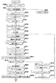
図1は、本発明の第1の実施形態である電子カメラの構成を示したブロック図である。 FIG. 1 is a block diagram showing a configuration of an electronic camera according to the first embodiment of the present invention.
図1に示すように本実施形態の電子カメラ100は、図示されない被写体像からの撮影光束が、撮影レンズ1及び光量を調節するための露出手段である絞り2を介して、図示する矢印方向に回動可能なクイックリターンミラー3に導かれる。クイックリターンミラー3の中央部はハーフミラーになっており、該クイックリターンミラー3がダウンした際に一部の光束が透過する。そして、この透過した光束は、クイックリターンミラー3に設置されたサブミラー4で反射され、AFセンサモジュール5に導かれる。
As shown in FIG. 1, in the
一方、クイックリターンミラー3で反射された撮影光束は、ペンタプリズム6、接眼レンズ7を介して撮影者の目に至る。
On the other hand, the photographing light beam reflected by the
また、クイックリターンミラー3がアップした際には、上記撮影レンズ1からの光束は、フィルタ9、機械シャッタであるフォーカルプレーンシャッタ10を介して撮像素子としてのCCD等に代表されるイメージセンサ11に至る。上記フィルタ9は2つの機能を有しているもので、1つは赤外線をカットし可視光線のみをイメージセンサ11へ導く機能であり、もう1つは光学ローパスフィルタとしての機能である。また、フォーカルプレーンシャッタ10は、先幕及び後幕を有して成るもので、撮影レンズ1からの光束を透過、遮断を制御する遮光手段である。
When the
なお、クイックリターンミラー3のアップ時には、サブミラー4は折り畳まれるようになっている。
The sub mirror 4 is folded when the
また、本実施形態の電子カメラ100は、当該電子カメラ全体の制御を司るCPUにより構成されるシステムコントローラ15を備え、後述する各部の動作を適宜制御する。
In addition, the
上記システムコントローラ15は、上記撮影レンズ1を光軸方向に移動してピント合わせを行うためのレンズ駆動機構16を制御するレンズ制御回路39と、上記絞り2を駆動するための絞り駆動機構17と、クイックリターンミラー3のアップダウンの駆動を行うためのミラー駆動機構18と、フォーカルプレーンシャッタ10のシャッタチャージを制御するシャッタチャージ機構19と、フォーカルプレーンシャッタ10の先幕、後幕の走行を制御するためのシャッタ制御回路20と、上記接眼レンズ7の近傍に配設された測光センサに接続された測光回路22と、同じく接眼レンズ7の近傍に設けられ撮影者300の視線を検出する視線検出部8に接続された視線検出回路21と、当該電子カメラ100を制御する上で調整が必要なパラメータが記憶されているEEPROM23と等が接続されている。
The system controller 15 includes a
また、当該電子カメラ100にはパーソナルコンピュータ(PC)に代表される外部制御装置200が接続可能になっており、通信インターフェース回路40を介して該パーソナルコンピュータ200とシステムコントローラ15とが通信可能になされている。
In addition, an
上記測光回路22に接続される測光センサは、図示されない被写体の輝度を測定するためのセンサであり、その出力は測光回路22を経てシステムコントローラ15へ供給される。
The photometric sensor connected to the
上記視線検出回路21は、撮影者300の視線を検出する視線検出部8からの情報を受け、この検出結果をシステムコントローラ15に送出する。システムコントローラ15は、該検出結果に基づいて複数のフォーカスエリアより特定のエリアを選択する。
The line-of-
また、上記システムコントローラ15は、上記レンズ駆動機構16を制御することにより、被写体像をイメージセンサ11上に結像する。また、システムコントローラ15は、設定されたAv値に基いて、絞り2を駆動する絞り駆動機構17を制御し、更に、設定されたTv値に基いて、上記シャッタ制御回路20へ制御信号を出力する。
The system controller 15 controls the
上記フォーカルプレーンシャッタ10の先幕、後幕は、駆動源がバネにより構成されており、シャッタ走行後次の動作のためにバネチャージを要する。シャッタチャージ機構19は、このバネチャージを制御するようになっている。
The front and rear curtains of the
また、上記システムコントローラ15には、画像データコントローラ25が接続されている。この画像データコントローラ25は、DSP(デジタル信号プロセッサ)により構成される補正データサンプル手段及び補正手段であり、イメージセンサ11の制御、該イメージセンサ11から入力された画像データの補正や加工などをシステムコントローラ15の指令に基いて実行するものである。
An
上記画像データコントローラ25には、イメージセンサ11を駆動する際に必要なパルス信号を出力するタイミングパルス発生回路27と、イメージセンサ11と共にタイミングパルス発生回路27で発生されたタイミングパルスを受けて、該イメージセンサ11から出力される被写体像に対応したアナログ信号をデジタル信号に変換するためのA/Dコンバータ28と、得られた画像データ(デジタルデータ)を一時的に記憶しておくDRAM29と、D/Aコンバータ30及び画像圧縮回路33とが接続されている。
The
上記DRAM29は、加工や所定のフォーマットへのデータ変換が行われる前の画像データを一時的に記憶するための記憶手段として使用される。
The
また、上記D/Aコンバータ30には、エンコーダ31を介して画像表示回路32が接続される。更に、画像圧縮回路33には、画像データ記録メディア34が接続される。
An
上記画像表示回路32は、イメージセンサ11で撮像された画像データを表示するための回路であり、一般にはカラーの液晶表示素子により構成される。
The
画像データコントローラ25は、DRAM29上の画像データを、D/Aコンバータ30によりアナログ信号に変換してエンコーダ回路31へ出力する。エンコーダ回路31はこのD/Aコンバータ30の出力を、上記画像表示回路32を駆動する際に必要な映像信号(例えばNTSC信号)に変換する。
The
上記画像圧縮回路34は、DRAM29に記憶された画像データの圧縮や変換(例えばJPEG)を行うための回路である。変換された画像データは、画像データ記録メディア34へ格納される。この記録メディアとしては、ハードディスク、フラッシュメモリ、フロッピー(登録商標)ディスク等が使用される。
The
さらにシステムコントローラ15には、当該電子カメラの動作モードの情報や露出情報(シャッタ秒時、絞り値等)の表示を行うための動作表示回路36と、ユーザが所望の動作を当該電子カメラに実行させるべく操作される多数のスイッチで構成される操作スイッチ(SW)37が接続されている。
The system controller 15 further includes an
次に、上記撮影レンズ1およびレンズ駆動機構16について図2、図3を参照して詳しく説明する。
Next, the photographing
図2は、本第1の実施形態の電子カメラにおける撮影レンズ及びレンズ駆動機構を示した要部外観斜視図であり、図3は、同電子カメラにおける撮影レンズ、レンズ駆動機構及びカメラ本体の一部を示した要部断面図である。 FIG. 2 is an external perspective view of a main part showing a photographing lens and a lens driving mechanism in the electronic camera of the first embodiment, and FIG. 3 is one of the photographing lens, lens driving mechanism and camera body in the electronic camera. It is principal part sectional drawing which showed the part.
図2に示すように、撮影レンズ1はフォーカシング枠52内に保持され、またフォーカシング枠52の一端にはフォーカシング枠ギヤ53が一体的に配設され、後述する動力伝達機構46に係合する。さらに、フォーカシング枠52の外周にはヘリコイド54が形成されている。
As shown in FIG. 2, the photographing
また、該撮影レンズ1を駆動するレンズ駆動機構16は、駆動源たるモータ41と、このモータ41の出力軸に設けたピニオンギヤ42およびこれに順次噛合するギヤ43,44,45よりなる動力伝達機構46と、ギヤ43と同軸に配設され同じ回転数で回転する回転スリット47と、該回転スリット47用のフォトインタラプタ48と、で構成される。
The
なお、上記動力伝達機構46は最終段で上記フォーカシング枠ギヤ53と噛合する。これにより上記モータ41の回転力は、上記動力伝達機構46を介して該フォーカシング枠ギヤ53に伝達され、この結果、フォーカシング枠52が回転する。
The
また上記フォトインタラプタ48から出力されるパルス信号は、レンズ制御回路39を介してシステムコントローラ15に入力されるようになっており、システムコントローラ15は該パルス信号をカウントすることで撮影レンズ1の繰り出し量を検出する。
The pulse signal output from the
図3に示すように、撮影レンズ1(フォーカシング枠52)及びレンズ駆動機構16は、カメラ本体の一部55に一体的に固設される鏡枠56内に配設される。また、鏡枠56の前端部には固定枠57がそのフランジ部で固設される。この固定枠57の枠部内周面にはヘリコイド57aが形成されていて、上記フォーカシング枠52に設けられたヘリコイド54と嵌合する。
As shown in FIG. 3, the photographing lens 1 (focusing frame 52) and the
このようにフォーカシング枠52は固定枠57と係合して鏡枠56に内包されるが、一方で上記レンズ駆動機構16、すなわち、モータ41、動力伝達機構46等は、フォーカシング枠52と鏡枠56との間に形成される空間に配設される。
Thus, the focusing
このようなフォーカシング枠52、レンズ駆動機構16の構成により、モータ41がCCW方向信号(システムコントローラ1からの指示による)によって同方向に回転すると、フォーカシング枠52は固定枠57に対して繰り出されるよう移動する。この繰り出しによる移動は、フォーカシング枠ギヤ53の後端部53bと固定枠57の後端面57bが当て付くまで可能である。
With such a configuration of the focusing
一方、CW方向信号によって同方向に回転すると、フォーカシング枠52は固定枠57に対して繰り込まれるよう移動する。この繰り込みによる移動は、フォーカシング枠ギヤ53の後端面53aとカメラ本体の一部55aが当て付くまで可能である。
On the other hand, when the CW direction signal rotates in the same direction, the focusing
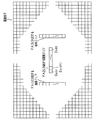
次に、上記AFセンサモジュール5について図4を参照して詳しく説明する。
図4に示すように、AFセンサモジュール5は、視野マスク62、コンデンサレンズ群64、セパレータレンズ群65、絞りマスク63、ラインセンサ66等で主要部が構成され、被写体61a〜61cからの光束を各フォーカスエリアFA1、FA2、FA3に対応する瞳分割光学系で分割し、1次元CCDである上記ラインセンサ66上に結像させ位相差方式による焦点検出を行うセンサである。
Next, the AF sensor module 5 will be described in detail with reference to FIG.
As shown in FIG. 4, the AF sensor module 5 includes a
すなわち、被写体61a、61b、61cに対応する撮影エリア61中のフォーカスエリアFA1、FA2、FA3の被写体光は、撮影レンズ1を透過して視野マスク62により迷光が除去され、それぞれに対応するコンデンサレンズ群64(コンデンサレンズCL1、CL2、CL3)に入射する。
That is, the subject light in the focus areas FA1, FA2, and FA3 in the photographing
被写体光はこのコンデンサレンズ群64により絞りマスク63の対応する開口部瞳位置に投影される。上記絞りマスク63の開口部には、各対となるセパレータレンズ群65(セパレータレンズSL1a/SL1b、SL2a/SL2b、SL3a/SL3b)が配設されている。そして、コンデンサレンズCL1〜3と絞りマスク63の開口部により決定される撮影レンズ1の射出瞳からの光は、上記各セパレータレンズSL1a/SL1b、SL2a/SL2b、SL3a/SL3bによりそれぞれ対応するラインセンサ66のS1、S2、ステップS3上に結像する。
The subject light is projected by the
なお、各ラインセンサS1〜ステップS3は、一対となる2つの群、a群とb群により構成されており、一対のセパレータレンズが構成する2つの像が各像のセンサ上に投影される。このラインセンサS1〜ステップS3上の対となる2つの像の間隔を検出することにより、それぞれのセンサに対応するフォーカスエリアFA1〜FA3の被写体61a〜61cのフィルム面に対するデフォーカス量、即ち、撮影レンズの合焦位置からのずれ量を求めることができる。上記デフォーカス量は公知の技術である位相差演算方法に基いて求めることができる。
Each of the line sensors S1 to S3 is composed of a pair of two groups, a group and b group, and two images formed by the pair of separator lenses are projected onto the sensor of each image. By detecting the distance between two pairs of images on the line sensors S1 to S3, the defocus amounts with respect to the film surfaces of the
上記ラインセンサS1〜ステップS3の出力端は上記システムコントローラ15に接続されている。ラインセンサS1〜ステップS3の出力のシステムコントローラ15への取り込みは、まず、その出力が焦点検出回路38内のインターフェース回路に入力される。そして、インターフェース回路に設けられるラインセンサ制御回路により積分され、適正レベルに達すると、その積分出力がA/Dコンバータによりデジタル値に変換され、システムコントローラ15へ転送される。
The output terminals of the line sensors S1 to S3 are connected to the system controller 15. In capturing the outputs of the line sensors S1 to S3 into the system controller 15, first, the outputs are input to the interface circuit in the
次に、図5を参照して、システムコントローラ15が実行するメインルーチンについて説明する。 Next, the main routine executed by the system controller 15 will be described with reference to FIG.
操作スイッチ37の1つであるパワースイッチがオンすると、システムに電源が供給されシステムコントローラ15が動作を開始する。システムコントローラ15は、まず初期設定を行う(ステップS100)。すなわち、メモリ、I/Oポート、システムコントローラ1(CPU)に接続された各回路の初期化や画像データコントローラ25(DSP)の起動動作等である。 When a power switch that is one of the operation switches 37 is turned on, power is supplied to the system and the system controller 15 starts operating. First, the system controller 15 performs initial setting (step S100). That is, initialization of each circuit connected to the memory, the I / O port, the system controller 1 (CPU), the starting operation of the image data controller 25 (DSP), and the like.
次にステップS101においてシステムコントローラ15は、通信インターフェース回路40を介して外部制御装置(パーソナルコンピュータ)200からの通信要求があるか否かを判定する。ここで通信要求があれば、ステップS102へ移行し、サブルーチン“テストモード”を実行する。一方、通信要求がなければ、ステップS103へ移行する。
Next, in step S <b> 101, the system controller 15 determines whether there is a communication request from the external control device (personal computer) 200 via the
なお、上記テストモードには、カメラの製造工程において必要な調整動作や、ユーザがカメラ内部に記憶した画像データを読み出すための動作等が含まれている。 The test mode includes an adjustment operation necessary in the camera manufacturing process, an operation for reading image data stored in the camera by the user, and the like.
ステップS103においてシステムコントローラ15は、測光回路22から被写体の輝度情報を入力する。そして、この輝度情報に基づいてイメージセンサ11(CCD)の積分時間を示すシャッタ秒時、絞りの設定値を決定する。さらにステップS104において、カメラの動作状態を示すデータ、シャッタ秒時、絞りの設定値などを動作表示回路36に対して出力する。
In step S <b> 103, the system controller 15 inputs subject brightness information from the
次にシステムコントローラ15は、ステップS105において操作スイッチ37の1つであるレリーズスイッチの状態を検出する。ここで該スイッチがONしている場合はステップS108へ移行し、OFFならばステップS106へ移行する。 Next, in step S105, the system controller 15 detects the state of a release switch that is one of the operation switches 37. If the switch is ON, the process proceeds to step S108, and if OFF, the process proceeds to step S106.
上記ステップS106においてシステムコントローラ15は、上記パワースイッチの状態を検出する。ここでパワースイッチがOFFならば、システムは動作を止めなければならない。したがって、ステップS106からステップS107へ移行し、システムDownのための処理を実行後、システムコントローラ15は動作を停止する。一方、パワースイッチがONならば、カメラとしての動作をつづけるため、ステップS103へ移行する。 In step S106, the system controller 15 detects the state of the power switch. If the power switch is OFF, the system must stop operating. Therefore, the process proceeds from step S106 to step S107, and the system controller 15 stops the operation after executing the process for the system down. On the other hand, if the power switch is ON, the process proceeds to step S103 in order to continue the operation as a camera.
上記ステップS105からステップS108へ移行すると、システムコントローラ15は、視線検出回路21の出力に基づき3つのフォーカスエリア(FA1,FA2,FA3,図4参照)の中から、1つのフォーカスエリアを選択する。そして、ステップS109において、焦点検出回路38に対して選択したエリアに対応するラインセンサ66の積分を指示する。
After shifting from step S105 to step S108, the system controller 15 selects one focus area from the three focus areas (FA1, FA2, FA3, see FIG. 4) based on the output of the line-of-
ステップS110においてシステムコントローラ15は、選択したラインセンサ66の積分動作が終了するまで待機する。
In step S110, the system controller 15 stands by until the integration operation of the selected
ここでラインセンサ66の積分動作が終了すると、焦点検出回路38は、ラインセンサ66を構成する個々のエレメントの出力を回路内においてA/D変換してシステムコントローラ15へ出力する。システムコントローラ15は、この変換されたデータをステップS111で入力する。
When the integration operation of the
次にシステムコントローラ15は、ステップS112において一対のセパレータレンズ65がラインセンサ66上へ形成した2つの像の相対的距離(2像間隔)を算出する。なおこの算出手法としては公知の手法を利用するものとし、ここでの説明は省略する。
Next, the system controller 15 calculates the relative distance (two-image interval) between the two images formed by the pair of
さらにシステムコントローラ15はステップS113において、上記EEPROM23から基準2像間隔を読み出す。この基準2像間隔とは、撮影レンズ1による被写体の像が撮像素子上に結像した際に上記ラインセンサ66上に形成された2つの像の相対距離である。なお、この2像間隔はサブルーチン“テストモード”の中で測定される。
Further, the system controller 15 reads the reference two-image interval from the
この後ステップS114においてシステムコントローラ15は、上記ステップS112で求めた現在の2像間隔と基準2像間隔の差からデフォーカス量を算出する。 Thereafter, in step S114, the system controller 15 calculates a defocus amount from the difference between the current two-image interval obtained in step S112 and the reference two-image interval.
表1はEEPROM23に記憶された基準2像間隔を示している。

本実施形態では、3つのフォーカスエリア(FA1,FA2,FA3)それぞれにEEPROM23上の特定のアドレスを定め、それぞれの基準2像間隔を記憶させている。撮影レンズ1の収差によって最良の結像ポイントは、焦点検出を行う位置によって変化する。したがって3つのフォーカスエリアそれぞれに基準2像間隔を記憶する必要がある。
In the present embodiment, specific addresses on the
なお、本実施形態の電子カメラでは単焦点レンズを採用しているが、ズームレンズを使用した場合は、焦点距離の変化に伴い収差も変化する。この場合は焦点距離に応じた基準2像間隔を記憶する。 Note that the electronic camera of the present embodiment employs a single focus lens. However, when a zoom lens is used, the aberration changes as the focal length changes. In this case, the reference two-image interval corresponding to the focal length is stored.
次にデフォーカス量検出の原理を図11、図12を参照して説明する。
図に示すように、撮像素子上にピントがあっているとき、ラインセンサ上の2像間隔はある値をとる。この値は設計上求めることができるが、実際には、部品の寸法、バラツキ、や組立て上の誤差によって設計値と同じとはならない。したがって、実際には測定しなければこの2像間隔(基準2像間隔Lo)を求めることは困難である。図11より明らかなように、この基準2像間隔Loより2像間隔が狭まければ、前ピンであり、Loより広ければ後ピンである。
Next, the principle of defocus amount detection will be described with reference to FIGS.
As shown in the figure, when the image sensor is in focus, the interval between the two images on the line sensor takes a certain value. This value can be obtained by design, but in practice, it does not become the same as the design value due to the size, variation, and assembly error of parts. Therefore, it is difficult to obtain the two-image interval (reference two-image interval Lo) unless actually measured. As is clear from FIG. 11, if the two-image interval is narrower than the reference two-image interval Lo, it is a front pin, and if it is wider than Lo, it is a rear pin.
図12はAFセンサモジュール5の光学系からコンデンサレンズを省いたモデルを示した図である。 FIG. 12 is a view showing a model in which the condenser lens is omitted from the optical system of the AF sensor module 5.
図に示すように、主光線の角度をθ、セパレータレンズの倍率をβ、像の移動量をΔL,ΔL’とすると、デフォーカス量Lは以下の式で求まる。
ここでβtanθは、AFセンサモジュール5の設計上定まるパラメータである。 Here, β tan θ is a parameter determined by the design of the AF sensor module 5.
ΔL’は基準2像間隔(Lo)と現在の2像間隔(Lt)から求めることができる。 ΔL ′ can be obtained from the reference two-image interval (Lo) and the current two-image interval (Lt).
図5に戻って、システムコントローラ15はステップS115において、求めたデフォーカス量から合焦か非合焦かを判定する。ここで合焦と判定したときはステップS116へ移行する。 Returning to FIG. 5, in step S115, the system controller 15 determines whether in-focus or out-of-focus from the obtained defocus amount. If it is determined that the subject is in focus, the process proceeds to step S116.
ステップS116ではステップS103で決定した条件で撮像素子を積分し、画像データを取り込む。画像データは所定のフォーマットへ変換された後、画像データ記録メディアへ格納される。 In step S116, the image sensor is integrated under the conditions determined in step S103, and image data is captured. The image data is converted into a predetermined format and then stored in the image data recording medium.
一方、ステップS115において非合焦と判定したときは、ステップS117へ移行する。このステップS117ではデフォーカス量をレンズの駆動量(Px:PIのパルス数)へ変換する。ここで前ピン状態ならばステップS118からステップS119へ移行し、モータ41をCW方向へ回転させる。これにより撮影レンズ1は繰り込まれる。この撮影レンズ1の駆動はフォトインタラプタ48の発生するパルスのカウント数がPxになるまで行われる。
On the other hand, when it determines with out-of-focus in step S115, it transfers to step S117. In step S117, the defocus amount is converted into a lens drive amount (Px: PI pulse number). If it is a front pin state here, it will transfer to step S119 from step S118, and will rotate the
ここでカウント数がPxになると、システムコントローラ15はステップS121からステップS122へ移行して、モータ41にブレーキをかけ撮影レンズ1の移動を止める。そして再度焦点検出動作を行うためステップS109へ移行する。
When the count number reaches Px, the system controller 15 proceeds from step S121 to step S122, brakes the
また、デフォーカスの方向が後ピンの場合は、システムコントローラ15は、ステップS118からステップS120へ移行し、撮影レンズ1は繰り出し方向へ駆動される。
When the defocus direction is the rear pin, the system controller 15 proceeds from step S118 to step S120, and the photographing
次に、図6,図7を参照して上記サブルーチン“テストモード”について説明する。なお、以下の動作説明は、基本的にはシステムコントローラ15の動作として説明する。
システムコントローラ15はステップS200において、外部制御装置200から動作モードを示すデータを入力する。ステップS201では動作モードが、基準2像間隔測定モードであるか判定する。ここで基準2像間隔測定モードならばステップS203へ移行し、そうでなければステップS202へ移行する。なお、基準2像間隔測定モードを実行するときは、予め図13に示すようなベンチに当該電子カメラ100を固定する。図中、チャート(A)は、たとえば白黒のストライプが使用される。またストライプのピッチ(P)と電子カメラ100からチャートまでの距離(M)は、撮影レンズ1の解像力と撮像素子を構成する画素のピッチ等を考慮して適切な値を設定する。
Next, the subroutine “test mode” will be described with reference to FIGS. The following description of the operation is basically described as the operation of the system controller 15.
In step S200, the system controller 15 inputs data indicating the operation mode from the
次にシステムコントローラ15はステップS203において動作カウンタをクリアする。さらにステップS204において、レンズ制御回路39に対してモータ41をCW方向へ回転させるための駆動信号を出力する。これにより、フォーカシング枠52は繰り込み方向への移動を開始する。
Next, the system controller 15 clears the operation counter in step S203. In step S204, a driving signal for rotating the
上記モータ41はフォーカシング枠ギヤ53の部位53aとカメラ本体の部位55aが当てつくまで回転し続け、該モータ41が回転する限りフォトインタラプタ48はパルス信号を出しつづける。この後、上記フォーカシング枠ギヤ53の部位53aとカメラ本体の部位55aとが当てついてモータ41が停止すると該パルス信号は消失する。
The
ステップS205においてシステムコントローラ15はこのパルス信号を検出し、該パルス信号が消失するまで待機する。そしてパルス信号が無くなるとステップS205からステップS206へ移行し、レンズ制御回路39に対してブレーキ信号を出力する。これによりモータ41は停止する。このとき、フォーカシング枠52はもっとも繰り込んだ位置に停止していることになる。
In step S205, the system controller 15 detects this pulse signal and waits until the pulse signal disappears. When the pulse signal disappears, the process proceeds from step S205 to step S206, and a brake signal is output to the
さらにイメージセンサ11に対して撮影レンズ1の光束を導くため、システムコントローラ15はステップS207においてクイックリターンミラー3をUP状態へ駆動する。
Further, in order to guide the luminous flux of the photographing
システムコントローラ15はステップS208において、上記絞り2を所定の位置まで駆動する。このとき絞り2は、イメージセンサ11においてコントラストの最大値を検出しやすい値になるまで駆動される。なおレンズの特性によっては開放値がベストとは限らないが、一般には、絞り2を最も開放にする値でよい。
In step S208, the system controller 15 drives the
ステップS209においてシステムコントローラ15はフォーカルプレーンシャッタ10を開くよう各部を制御する。さらにステップS210では、画像データコントローラ25(DSP)に対してラインセンサ66の積分動作を指示する。ステップS2101では所定時間の間、待機する。そして積分時間が終わると、ステップS211へ移行し、フォーカルプレーンシャッタ10を閉じる。
In step S209, the system controller 15 controls each unit to open the
システムコントローラ15は、ステップS212において次回の動作に備えてフォーカルプレーンシャッタ10のチャージ動作を行う。ステップS213では画像データコントローラ25に対してイメージセンサ11から画像データを取り込むように指示する。ステップS214では、画像データコントローラ25へフォーカスエリアの位置情報を出力する。
In step S212, the system controller 15 charges the
画像データコントローラ25では3つのフォーカスエリアに対応する画像データからコントラスト値を算出し、システムコントローラ15を介してDRAM29へ記憶する。
The
図8は、イメージセンサ11とコントラスト演算を行う画素エリアの位置の関係を示した説明図である。
FIG. 8 is an explanatory diagram showing the positional relationship between the
コントラストの演算は、例えば、次式に基いて実行される。
ここで、Saddは、演算を行うエリアの先頭画素データが記憶されたメモリのアドレスであり、Eaddは、演算を行うエリアの最頭画素データが記憶されたメモリのアドレスである。また、Xnは、イメージセンサ11を構成する個々の画素の出力値である。
Here, Sadd is the address of the memory where the top pixel data of the area where the calculation is performed is stored, and Eadd is the address of the memory where the top pixel data of the area where the calculation is performed is stored. Xn is an output value of each pixel constituting the
画像データコントローラ25におけるコントラスト演算が終了すると、システムコントローラ15はステップS215において動作カウンタのカウント値が、所定の回数(Nx)に達したか判定する。ここで動作カウンタの値がNxでないときは、ステップS215からステップS216へ移行する。
When the contrast calculation in the
システムコントローラ15は、ステップS216では動作カウンタをインクリメントする。またステップS217では、レンズ制御回路39に対してモータ41をCCW方向へ回転させるための駆動信号を出力する。これによりフォーカシング枠52は繰り出し方向への移動を開始する。
In step S216, the system controller 15 increments the operation counter. In step S217, a drive signal for rotating the
ステップS218では、システムコントローラ15は、フォトインタラプタ48で発生するパルス信号の数が所定値PΔに等しくなるまで待機する。そしてパルスカウンタ値がPΔになると、ステップS218からステップS219へ移行する。ステップS219では、モータ41にブレーキをかけ、撮影レンズ1の移動を止める。そして再度イメージセンサ11の出力値からコントラスト演算を行うためステップS209へ移行する。
In step S218, the system controller 15 waits until the number of pulse signals generated by the
なおコントラスト値を求める動作と撮影レンズ1を所定量繰り出す動作は、その回数がNxに達するまで繰り返される。そして動作回数がNxに達すると、ステップS215からステップS220へ移行する。このステップS220ではシステムコントローラ15は絞り2を開放位置へ戻す。
The operation for obtaining the contrast value and the operation for extending the photographing
次にシステムコントローラ15は、ステップS221においてクイックリターンミラー3をDown位置へもどす。さらにステップS222では、画像データコントローラ25から、画像データに基づいて演算したコントラスト値を入力する。
Next, the system controller 15 returns the
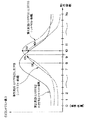
図9は、動作回数を横軸に、コントラスト値を縦軸として、イメージセンサ11の出力から求めたコントラスト値をプロットした説明図である。
FIG. 9 is an explanatory diagram in which the contrast value obtained from the output of the
ステップS223においてシステムコントローラ15は、何回目の動作においてコントラスト値が最大になったか求める。そしてコントラスト値が最大のときの動作回数にPΔをかける。この計算結果がコントラストピーク位置データ(Ppeak)となる。 In step S223, the system controller 15 determines how many times the contrast value is maximized. Then, PΔ is applied to the number of operations when the contrast value is maximum. This calculation result is contrast peak position data (Ppeak).
図9から分かるように、第1のフォーカスエリアFA1に対するコントラスト値が最大となるのは10回目の動作である。仮にPΔを10パルスとすれば第1のフォーカスエリアFA1に対するピーク位置データは、100(10回目×10)パルスとなる。つまり、撮影レンズ1を最も繰り込んだ位置から100パルス分該レンズを繰り出せばコントラストがピークとなり、チャートの像が撮像素子上に結像することになる。
As can be seen from FIG. 9, the maximum contrast value for the first focus area FA1 is the tenth operation. If PΔ is 10 pulses, the peak position data for the first focus area FA1 is 100 (10th × 10) pulses. That is, if the lens is extended for 100 pulses from the position where the photographing
同様に第2のフォーカスエリアFA2に対してもピーク位置データを求めると80パルスとなる。 Similarly, when the peak position data is obtained for the second focus area FA2, 80 pulses are obtained.
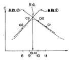
一方、第3のフォーカスエリアFA3のようにコントラストの最大値が9回目と10回目の間にある場合は、図10に示す手法によって9回目と10回目の間のどこに最大値が存在するかを算出することができる。すなわち、コントラストカーブの山左側を8回目と9回目のコントラスト値C8,C9を使って、直線近似(直線1)する。同様に、C10とC11を使って、コントラストカーブの山右側を直線近似(直線2)する。そして2つの直線の交点を求めれば、どこにコントラストの最大値が存在するかを知ることができる。 On the other hand, when the maximum contrast value is between the ninth and tenth times as in the third focus area FA3, it is determined where the maximum value exists between the ninth and tenth times by the method shown in FIG. Can be calculated. In other words, the left side of the contrast curve is linearly approximated (straight line 1) using the eighth and ninth contrast values C8 and C9. Similarly, a linear approximation (straight line 2) is performed on the right side of the contrast curve using C10 and C11. If the intersection of two straight lines is obtained, it is possible to know where the maximum contrast value exists.
そして、求めた値がたとえば、9.4回目ならば、第3のフォーカスエリアFA3のピーク位置データは94パルスとなる。上記3つのフォーカスエリアに対するピーク位置データを纏めると表2のようになる。
ここで、コントラスト検出動作の動作回数(Nx)およびレンズの繰り出し量(PΔ)は、撮影レンズ1の光学的特性、モータ41の回数をレンズ1の移動へ変換する際の変換比率、撮影レンズ1を支える枠の寸法ばらつき等のパラメータを考慮して決定する必要がある。
Here, the number of contrast detection operations (Nx) and the lens feed amount (PΔ) are the optical characteristics of the photographing
なお、これらのパラメータは一律に決定できず予期し得ない変更も考えられる。本実施形態では、かかる事情を考慮して、上記Nx,PΔをEEPROM23に記憶することとした。これにより必要に応じて最適な値を設定することが可能となった。
It should be noted that these parameters cannot be uniformly determined, and an unexpected change may be considered. In the present embodiment, in consideration of such circumstances, the Nx and PΔ are stored in the
次にシステムコントローラ15は、パーソナルコンピュータ200がチャートを切り換えるまでステップS2231で待機する。コントラストピーク位置を検出するためのチャートは、位相差方式のAFセンサで焦点検出するためのチャートとしては適さないからである。
Next, the system controller 15 stands by in step S2231 until the
システムコントローラ15は、次にステップS224において選択カウンタへ“1”をセットする。この選択カウンタの値はフォーカスエリアを示している。 In step S224, the system controller 15 next sets “1” to the selection counter. The value of this selection counter indicates the focus area.
この後のステップS225〜ステップS227の動作は、上記ステップS204〜ステップS206の動作と同じである。すなわち、システムコントローラ15は撮影レンズ1を最も繰り込んだ位置まで移動する。コントラストピーク位置データは、該撮影レンズ1を最も繰り込んだ位置を基準に測定されたデータである。したがって、コントラストピーク位置(合焦位置)まで撮影レンズ1を移動するには、ステップS225〜ステップS227の処理が必要になる。
The subsequent operations in steps S225 to S227 are the same as the operations in steps S204 to S206. That is, the system controller 15 moves to the position where the taking
次にシステムコントローラ15は、ステップS2271において選択カウンタの値に対応するフォーカスエリアのピーク位置データを当該システムコントローラ15内のメモリから読み出す。たとえば、選択カウンタの値が“1”ならば、第1のフォーカスエリアFA1のピーク位置データ(Ppeak)が読み出される。なお表2に示されるように、Ppeakは“100”になる。 Next, in step S 2271, the system controller 15 reads the focus area peak position data corresponding to the value of the selection counter from the memory in the system controller 15. For example, if the value of the selection counter is “1”, the peak position data (Ppeak) of the first focus area FA1 is read out. As shown in Table 2, Ppeak is “100”.
システムコントローラ15は次にステップS228〜ステップS230において、フォトインタラプタ48のパルスカウンタ数がPpeakに達するまで撮影レンズ1を繰り出す。このとき、ラインセンサ66のフォーカスエリアFA1に対応するエリアに形成された被写体像は合焦状態にある。このときのAFセンサモジュール5のラインセンサ66に形成された、2像間隔を求めなければならない。
Next, in step S228 to step S230, the system controller 15 extends the photographing
次にステップS231においてシステムコントローラ15は、フォーカスエリアFA1に対応するラインセンサ66の積分を行うように焦点検出回路38に対して指令を出す。そして、ステップS232においてラインセンサ66の積分が終了するまで待機する。そして積分が終了するとラインセンサ66の出力はA/D変換された後、システムコントローラ15へ出力される。
Next, in step S231, the system controller 15 issues a command to the
上記ラインセンサ66の出力データは、ステップS233においてシステムコントローラ15に読み込まれる。ステップS234ではシステムコントローラ15においてこのデータからフォーカスエリアFA1に対応する2像間隔が計算される。ここで求められた2像間隔データは、該フォーカスエリアFA1に対する基準2像間隔データである。さらにこのデータは、ステップS235においてEEPROM23の所定のアドレスへ記憶される。
The output data of the
次に、ステップS236においてシステムコントローラ15は選択カウンタの値が“3”であるか否かを判定する。ここで“3”でなければステップS237へ移行して選択カウンタをインクリメントする。そして次のフォーカスエリアに対しての基準2像間隔データを求めるためステップS225へ移行する。 Next, in step S236, the system controller 15 determines whether or not the value of the selection counter is “3”. If it is not “3”, the process proceeds to step S237 to increment the selection counter. Then, the process proceeds to step S225 to obtain reference two-image interval data for the next focus area.
このようにして3つのフォーカスエリアに対する基準2像間隔データの演算が終了すれば、選択カウンタの値は“3”となり、ステップS236からメインルーチンへリターンする。 When the calculation of the reference two-image interval data for the three focus areas is completed in this way, the value of the selection counter becomes “3”, and the process returns from step S236 to the main routine.
以上説明したように上記第1の実施形態に係る電子カメラによると、撮像素子の合焦位置調整を行う際に、撮像素子を取り外しての調整をする必要がないので調整工程を簡略化することができる。 As described above, according to the electronic camera according to the first embodiment, when adjusting the in-focus position of the image sensor, it is not necessary to perform adjustment after removing the image sensor, thereby simplifying the adjustment process. Can do.
また、オートコリメータのような特別な装置を用いずとも調整が可能となる。すなわち、簡単な装備しかもたないサービスセンタ等でにあっても正確な調整が実現できる。 Further, adjustment is possible without using a special device such as an autocollimator. That is, accurate adjustment can be realized even in a service center or the like that is simply equipped.
次に、本発明の第2の実施形態について説明する。
上記第1の実施形態においては、撮像素子上に被写体像が結像する撮影レンズの位置を基準にして基準2像間隔を決定した。ところで、AFセンサモジュール5を設計する際に設計上の基準2像間隔が決定される。したがって設計上の基準2像間隔を用いて、デフォーカス量を算出することも可能となる。そしてこのデフォーカス量からレンズの移動量(パルス数)を算出し、レンズを移動すれば設計上の合焦位置に被写体像が結像することになる。
Next, a second embodiment of the present invention will be described.
In the first embodiment, the reference two-image interval is determined based on the position of the photographing lens on which the subject image is formed on the image sensor. By the way, when designing the AF sensor module 5, a design reference two-image interval is determined. Accordingly, it is possible to calculate the defocus amount using the design reference two-image interval. Then, the amount of movement (number of pulses) of the lens is calculated from this defocus amount, and if the lens is moved, the subject image is formed at the designed focus position.
しかし撮像素子が設計値どおりにカメラ本体に取り付けられていない場合は、設計上の合焦位置と撮像素子の撮像面とが一致しない虞もある。また、AFセンサモジュール5の製造上発生する精度のばらつき等を考慮すると、設計上の合焦位置と撮像素子の撮像面とをより正確に一致させるさらなる工夫が必要となる。 However, when the image sensor is not attached to the camera body as designed, there is a possibility that the designed focus position and the image pickup surface of the image sensor do not match. Further, in consideration of variations in accuracy occurring in the manufacture of the AF sensor module 5, it is necessary to further devise to make the designed focus position and the imaging surface of the image sensor more accurately match.
本第2の実施形態の電子カメラはかかる点を考慮してなされており、設計上の合焦位置と撮像素子の撮像面とをより正確に一致することを可能としている。 The electronic camera according to the second embodiment is made in consideration of such points, and allows the design focus position and the imaging surface of the imaging device to be more accurately matched.
なお、本第2の実施形態に係る電子カメラの構成は、ブロック図で示す限り上記図1に示す第1の実施形態と同様であるので、ここでの詳しい説明は省略し、差異のみの言及にとどめる。 Since the configuration of the electronic camera according to the second embodiment is the same as that of the first embodiment shown in FIG. 1 as long as it is shown in the block diagram, detailed description thereof is omitted here, and only the difference is mentioned. Stay on.
図14は、本第2の実施形態の電子カメラにおいて、合焦位置と撮像面を一致させる手法を示したフローチャートであり、主としてシステムコントローラ15の動作を示す。 FIG. 14 is a flowchart showing a method for matching the in-focus position and the imaging surface in the electronic camera of the second embodiment, and mainly shows the operation of the system controller 15.
システムコントローラ15は、当該電子カメラの動作開始後、上記第1の実施形態と同様の初期設定等を経た後、ステップS300において、テストモードであるかどうか判定する。ここでテストモードでなければ、ステップS320へ移行する。 After starting the operation of the electronic camera, the system controller 15 undergoes initial settings and the like similar to those of the first embodiment, and then determines whether or not the test mode is in step S300. If it is not the test mode, the process proceeds to step S320.
このステップS320では、レリーズSWの状態を検出する。そして該レリーズSWがONされると、ステップS320からステップS321へ移行する。このステップS321ではAFセンサモジュール5において上記同様の積分動作が行われる。これはシステムコントローラ15の制御下に焦点検出回路38により制御される。
In step S320, the state of the release SW is detected. When the release SW is turned on, the process proceeds from step S320 to step S321. In step S321, the AF sensor module 5 performs the same integration operation as described above. This is controlled by the
上記積分が終了すると、システムコントローラ15はステップS322において当該センサデータを入力する。そしてステップS323ではこのデータに基づいて被写体の2像間隔を算出する。 When the integration is completed, the system controller 15 inputs the sensor data in step S322. In step S323, the distance between the two images of the subject is calculated based on this data.
次にシステムコントローラ15は、ステップS323において上記実際の2像間隔と設計上の2像間隔の差からデフォーカス量を算出する。そしてステップS325において該デフォーカス量をレンズの移動量(Px)へ変換する。これは、上記同様フォトインタラプタ48のパルス数である。
In step S323, the system controller 15 calculates a defocus amount from the difference between the actual two image interval and the designed two image interval. In step S325, the defocus amount is converted into a lens movement amount (Px). This is the number of pulses of the
ステップS326においてシステムコントローラ15は、偏差(ΔP)をEEPROM23から読み出す。この偏差(ΔP)は、テストモードで測定されるパラメータであり、該偏差は、AFセンサモジュール5の出力から求められたPxに対してさらにΔP分余分に移動(もしくはΔP分少なく移動)しないとイメージセンサ11(撮像素子)上に被写体の像が結像しないことを示す。
In step S <b> 326, the system controller 15 reads the deviation (ΔP) from the
ステップS327ではPxとΔPに基いて撮影レンズ1が駆動される。そして、ステップS328において所定の条件で、イメージセンサ11から画像データがシステムコントローラ15に取り込まれる。
In step S327, the photographing
一方、システムコントローラ15は、上記ステップS300においてテストモードと判定するとステップS301へ移行する。なお、このとき当該電子カメラ100は予め図13に示す如きベンチ等に取り付けられている。
On the other hand, if the system controller 15 determines that the test mode is in step S300, the system controller 15 proceeds to step S301. At this time, the
このステップS301では当該ベンチに係るチャートをチャートBにセットする。これはAFセンサモジュール5で焦点検出を行いやすくするためである。このチャートBがセットされるとステップS302〜ステップS306において焦点検出動作が行われる。なおこの動作は、ステップS321〜ステップS325と同じ動作である。 In this step S301, the chart related to the bench is set on the chart B. This is to facilitate the focus detection by the AF sensor module 5. When this chart B is set, a focus detection operation is performed in steps S302 to S306. This operation is the same operation as steps S321 to S325.
次に、システムコントローラ15は、ステップS307において、求められたPxに基いて撮影レンズ1を駆動する。さらにステップS308では上記ベンチに係るチャートがチャートAにセットされる。これは、イメージセンサ11による焦点検出動作を行いやすくするためである。
Next, in step S307, the system controller 15 drives the photographing
システムコントローラ15は、ステップS309においてイメージセンサ11の積分動作を行う。さらにステップS310でイメージセンサ11から画像データを取り込む。この後ステップS311において画像データにもとづいてコントラストの演算を行う。
The system controller 15 performs the integration operation of the
次に、ステップS312においてシステムコントローラ15は、コントラストが最大になったか否かを判定する。ここで最大でなければステップS313へ移行し、撮影レンズ1を所定量移動する。そして再度コントラストを求めるためステップS309へ移行する。
Next, in step S312, the system controller 15 determines whether or not the contrast is maximized. If it is not the maximum, the process proceeds to step S313, and the photographing
この後、撮影レンズ1の移動とコントラストの演算を繰り返して、コントラストのピークが検出されると、ステップS312からステップS314へ移行する。ステップS314では、システムコントローラ15は、上記ステップS307においてレンズが設定された位置を基準として、コントラストがピークとなった位置をフォトインタラプタ48のパルス数として求める。これが偏差(ΔP)となる。このパルス数はステップS315においてEEPROM23に記憶する。
Thereafter, the movement of the photographing
その他の作用は、上記第1の実施形態と同様であるので、ここでの詳しい説明は省略する。 Since other operations are the same as those in the first embodiment, detailed description thereof is omitted here.
以上説明したように上記第2の実施形態に係る電子カメラによると、上記第1の実施形態と同様の効果に加え、より正確に合焦位置と撮像面を一致させることができる。 As described above, according to the electronic camera of the second embodiment, in addition to the same effects as those of the first embodiment, the in-focus position and the imaging surface can be matched more accurately.
[付記]
以上詳述した如き本発明の実施形態によれば、以下の如き構成を得ることができる。即ち、
(1)撮像素子を用いて電子的撮像動作が可能な電子的撮像装置において、
撮像レンズを通過した光束を分割し、分割された光束がそれぞれ形成する像の相対距離に基いて撮像レンズの焦点位置を検出する第1焦点検出手段と、
撮像素子から出力される画像データのコントラストに基いて撮像レンズの焦点位置を検出する第2焦点検出手段と、
上記第1、第2焦点検出手段をそれぞれ制御し、それぞれ検出された撮像レンズの焦点位置の相対ずれを補正するための制御パラメータを測定する測定手段と
を具備することを特徴とする電子的撮像装置。
[Appendix]
According to the embodiment of the present invention described in detail above, the following configuration can be obtained. That is,
(1) In an electronic imaging device capable of performing an electronic imaging operation using an imaging device,
First focus detection means for dividing the light flux that has passed through the imaging lens and detecting the focal position of the imaging lens based on the relative distance between the images formed by the divided light flux;
Second focus detection means for detecting the focal position of the imaging lens based on the contrast of the image data output from the imaging device;
An electronic imaging system comprising: a measuring unit that controls the first and second focus detection units and measures a control parameter for correcting a relative shift of the detected focal position of the imaging lens. apparatus.
1…撮影レンズ
2…絞り
3…クイックリターンミラー
4…サブミラー
5…AFセンサモジュール
6…ペンタプリズム
7…接眼レンズ
8…視線検出部
9…フィルタ
10…レンズシャッタ
11…イメージセンサ
15…システムコントローラ
16…レンズ駆動機構
20…シャッタ制御回路
21…視線検出回路
22…測光回路
23…EEPROM
25…画像データコントローラ
29…DRAM
36…動作表示回路
37…操作スイッチ
38…焦点検出回路
39…レンズ制御回路
40…通信インターフェイス回路
66…ラインセンサ
100…電子カメラ
200…パーソナルコンピュータ
300…撮影者
DESCRIPTION OF
25 ...
36 ...
Claims (3)
撮像レンズを通過した光束が形成する像を光電変換した画像信号を出力すると共に、画像信号のコントラストを評価して該撮像レンズの焦点状態に関する第2オートフォーカスデータを出力する第2焦点検出手段と、
通常モードとテストモードとに設定可能なモード設定手段と、
上記テストモードにあるとき、上記第1、第2焦点検出手段を制御して上記第1、第2オートフォーカスデータの相対ずれデータを記憶すると共に、上記通常モードにあっては上記第1オートフォーカスデータと記憶した上記相対ずれデータとに基いて上記撮像レンズを駆動する制御手段と、
を具備することを特徴とする電子的撮像装置。 First focus detection that photoelectrically converts a pair of images formed by a pair of light beams that have passed through the imaging lens, detects a relative interval between the pair of images, and outputs first autofocus data relating to a focus state of the imaging lens. Means,
A second focus detection unit that outputs an image signal obtained by photoelectrically converting an image formed by a light beam that has passed through the imaging lens, and that outputs a second autofocus data relating to a focus state of the imaging lens by evaluating a contrast of the image signal; ,
Mode setting means that can be set to normal mode and test mode;
When in the test mode, the first and second focus detection means are controlled to store relative deviation data of the first and second autofocus data, and in the normal mode, the first autofocus is stored. Control means for driving the imaging lens based on the data and the stored relative deviation data;
An electronic imaging apparatus comprising:
Priority Applications (1)
| Application Number | Priority Date | Filing Date | Title |
|---|---|---|---|
| JP2006014443A JP2006178491A (en) | 2006-01-23 | 2006-01-23 | Electronic imaging apparatus |
Applications Claiming Priority (1)
| Application Number | Priority Date | Filing Date | Title |
|---|---|---|---|
| JP2006014443A JP2006178491A (en) | 2006-01-23 | 2006-01-23 | Electronic imaging apparatus |
Related Parent Applications (1)
| Application Number | Title | Priority Date | Filing Date |
|---|---|---|---|
| JP10448699A Division JP4331314B2 (en) | 1999-04-12 | 1999-04-12 | Single-lens reflex type electronic imaging device |
Publications (1)
| Publication Number | Publication Date |
|---|---|
| JP2006178491A true JP2006178491A (en) | 2006-07-06 |
Family
ID=36732586
Family Applications (1)
| Application Number | Title | Priority Date | Filing Date |
|---|---|---|---|
| JP2006014443A Pending JP2006178491A (en) | 2006-01-23 | 2006-01-23 | Electronic imaging apparatus |
Country Status (1)
| Country | Link |
|---|---|
| JP (1) | JP2006178491A (en) |
Cited By (1)
| Publication number | Priority date | Publication date | Assignee | Title |
|---|---|---|---|---|
| JP2009086317A (en) * | 2007-09-28 | 2009-04-23 | Fujifilm Corp | Single-lens reflex photographic device and method of adjusting single-lens reflex photographic device |
-
2006
- 2006-01-23 JP JP2006014443A patent/JP2006178491A/en active Pending
Cited By (1)
| Publication number | Priority date | Publication date | Assignee | Title |
|---|---|---|---|---|
| JP2009086317A (en) * | 2007-09-28 | 2009-04-23 | Fujifilm Corp | Single-lens reflex photographic device and method of adjusting single-lens reflex photographic device |
Similar Documents
| Publication | Publication Date | Title |
|---|---|---|
| JP4331314B2 (en) | Single-lens reflex type electronic imaging device | |
| JP4766133B2 (en) | Imaging device | |
| JP5020651B2 (en) | Imaging apparatus and imaging system | |
| JP5195506B2 (en) | Imaging apparatus and image composition method | |
| CN101247476A (en) | Single lens reflex type electronic imaging apparatus | |
| US6463214B1 (en) | Multi-point autofocus system | |
| WO2010021195A1 (en) | Focal point detecting device | |
| JP2006251065A (en) | Hybrid af camera | |
| JP5206292B2 (en) | Imaging apparatus and image recording method | |
| JP5966299B2 (en) | FOCUS DETECTION DEVICE AND IMAGING DEVICE HAVING THE SAME | |
| JP5776191B2 (en) | Focus detection apparatus and imaging apparatus | |
| JP4950634B2 (en) | Imaging apparatus and imaging system | |
| JP4865275B2 (en) | Focus detection apparatus and imaging apparatus | |
| JP2006178491A (en) | Electronic imaging apparatus | |
| JP4847352B2 (en) | Imaging apparatus and control method thereof | |
| JP2008040084A (en) | Optical device | |
| JP5402189B2 (en) | Focus adjustment device and imaging device provided with the same | |
| JP5531607B2 (en) | Focus detection apparatus and imaging apparatus | |
| JP2017021177A (en) | Range-finding point upon lens vignetting, range-finding area transition method | |
| JP5171124B2 (en) | Focus adjustment device, imaging device, and focus adjustment method | |
| JP2007240566A (en) | Focus detecting device, optical apparatus and camera | |
| JP4928236B2 (en) | Imaging apparatus and imaging system | |
| JP2014215340A (en) | Imaging apparatus | |
| JP2013083768A (en) | Focus detection device and imaging apparatus | |
| JP2022059763A (en) | Aberration correction method, program, and image capturing device |
Legal Events
| Date | Code | Title | Description |
|---|---|---|---|
| A131 | Notification of reasons for refusal |
Free format text: JAPANESE INTERMEDIATE CODE: A131 Effective date: 20090303 |
|
| A02 | Decision of refusal |
Free format text: JAPANESE INTERMEDIATE CODE: A02 Effective date: 20090707 |