JP2006174939A - Phlegm aspiration tube driving device and phlegm aspirator - Google Patents
Phlegm aspiration tube driving device and phlegm aspirator Download PDFInfo
- Publication number
- JP2006174939A JP2006174939A JP2004369640A JP2004369640A JP2006174939A JP 2006174939 A JP2006174939 A JP 2006174939A JP 2004369640 A JP2004369640 A JP 2004369640A JP 2004369640 A JP2004369640 A JP 2004369640A JP 2006174939 A JP2006174939 A JP 2006174939A
- Authority
- JP
- Japan
- Prior art keywords
- suction
- phlegm
- tube
- suction pipe
- pipe
- Prior art date
- Legal status (The legal status is an assumption and is not a legal conclusion. Google has not performed a legal analysis and makes no representation as to the accuracy of the status listed.)
- Pending
Links
Images


Abstract
Description
本発明は自発呼吸が困難な患者の気管に気管カニュ-レを装着し、該気管カニューレに接続された多分岐管に人工呼吸器とともに接続して、痰を吸引・除去(以後単に吸引または吸痰)する吸痰装置に関する。 In the present invention, a tracheal cannula is attached to the trachea of a patient having difficulty in spontaneous breathing, and connected to a multi-branch tube connected to the tracheal cannula together with a ventilator to suck and remove sputum (hereinafter simply aspirated or sucked). I) It relates to a suction device.
なお、以後の説明において,諸要素の患者側の端部を末端、外部側の端部を根元端と呼んで区別する。 In the following description, the end on the patient side of each element is called the end, and the end on the outside is called the root end.
自発呼吸機能が低下あるいは停止した患者に対して,気管切開して取り付けた気管カニューレを通じて人工呼吸器による換気が行われることがある。しかし、人工呼吸器には痰を吸引する機能がないため,気管内に痰が溜まると呼吸困難になってしまい、患者に非常な苦痛と恐怖を与える。そこで、定時的もしくは患者の求めに応じて、痰を除去する必要がある。 Patients with reduced or stopped spontaneous breathing may be ventilated with a ventilator through a tracheal cannula attached through tracheostomy. However, since the ventilator does not have a function of sucking sputum, if sputum accumulates in the trachea, it becomes difficult to breathe, which causes great pain and fear to the patient. Therefore, it is necessary to remove wrinkles on a regular basis or according to the patient's request.
介護者による吸痰の場合,気管カニューレの根元端に接続された多分岐管の通常は閉鎖されている接続口を開放し、該開放部から吸引装置に連なる吸痰管を挿入して吸痰管の末端を気管内の痰に到達させ、それから吸痰管の根元端と吸引装置を導通させて痰の吸引を開始する。痰の吸引を継続しつつ吸痰管を引き抜き、痰を吸引し終わったら、吸痰管の根元端と吸引装置との導通を断ち,吸痰管を前記開放部から引き抜き,開放部を塞いで吸引を終了する。 In the case of sucking by a caregiver, the normally closed connection port of the multi-branch tube connected to the root end of the tracheal cannula is opened, and the suction tube connected to the suction device is inserted from the open portion to suck The end of the tube is allowed to reach the soot in the trachea, and then the suction of the soot is started by connecting the root end of the suction tube and the suction device. Pull out the suction tube while continuing suction of the soot, and when suction is finished, disconnect the suction tube root end from the suction device, pull out the suction tube from the open part, and close the open part. End suction.
吸痰は昼夜を問わず1乃至2時間おきに、あるいは痰によって突然呼吸困難になったときには臨機に行う必要があるが,現在の吸痰作業は資格を有する医療従事者もしくは患者の家族しかこれを行えない制約があるため,介護者に過重な負担がかかる課題を抱えており,患者の自宅療養化の妨げにもなっている。また、痰によって突然呼吸困難になった場合は介護者が到着するまでの間に患者が非常な苦しみや恐怖を受ける問題もある。 Sucking should be done every one or two hours, day or night, or in the event of sudden dyspnea due to sputum, but current sucking work should only be performed by qualified health care workers or patient families. Because there are restrictions that can not be performed, there is a problem that the caregiver is overburdened, and it also hinders the patient's home treatment. In addition, if a person suddenly has difficulty breathing due to hesitation, there is also a problem that the patient suffers a lot of suffering and fear before the caregiver arrives.
そこで、患者自身の指令もしくは状況の変化の検出によって自動的に吸痰作業を行えるようにすることが要望されており、そのための吸痰装置が提案されている。 Therefore, it is desired to be able to automatically perform the sucking operation by detecting the patient's own command or the change of the situation, and a sucking device for that purpose has been proposed.
従来の吸痰装置の第1の例である特許公開番号2002-219175「人工呼吸吸引両用アダプタ及び自動吸引装置」は人工呼吸器からの送気を直接気道に送り込むためのカニューレ本管をふさいでいる痰を自動的に吸引するための装置を提案しており,該装置は人工呼吸器につながる呼吸開閉弁と痰吸引管につながる吸引管開閉弁を備えた人工呼吸吸引両用アダプタを人工呼吸用カニューレに接続し,該2種類の弁の一方が開けば他方が閉じるように操作して,人工呼吸用カニューレ内の痰を吸引できるようにした装置である。本吸痰装置は痰吸引のための吸痰管は使用しない。 Patent Publication No. 2002-219175 “Adaptive Ventilation Adapter and Automatic Suction Device”, which is a first example of a conventional suction device, covers the main tube of the cannula for directing the air supply from the ventilator to the airway. A device for automatically sucking a sputum is proposed. This device uses a respirator adapter with a respiration opening / closing valve connected to a ventilator and a suction tube opening / closing valve connected to a sputum suction tube for artificial respiration. The device is connected to a cannula and operated so that when one of the two types of valves is opened, the other is closed, so that the sputum in the cannula for artificial respiration can be sucked. This suction device does not use a suction pipe for soot suction.
従来の吸痰装置の第2の例である特許公開番号2002-177378「気道内の痰の吸引装置」は気管カニューレに接続するコネクタの根元端に内筒蛇管と外筒蛇管とから成る二重蛇管の末端部を連結し,一方、該二重蛇管の根元端部には吸引ラインに接続するカテーテルを取り付けた支持部を連結し,さらに上記両端部の連結状態を内筒蛇管と外筒蛇管とで形成される空隙が密閉状態になるように構成し,この空隙と吸気ラインとを連通させる連通部を上記支持部に設けて上記空隙内の圧力を吸引時には低圧になって通常は伸びている内筒蛇管と外筒蛇管とを吸引時には縮めることを可能にした吸痰装置であって、前記コネクタを介して気管カニューレに連結し、気管カニューレを介してカテーテルを気管内に挿抜できるようにした吸痰装置を提案している。 Patent Publication No. 2002-177378, “a suction device for sputum in the airway”, which is a second example of a conventional suction device, is a dual type consisting of an inner tube and an outer tube at the base end of a connector connected to a tracheal cannula. The end portion of the snake tube is connected, while the support portion to which the catheter connected to the suction line is attached is connected to the base end portion of the double snake tube. The air gap is formed in a hermetically sealed state, and a communication part for communicating the air gap with the intake line is provided in the support part, so that the pressure in the air gap becomes low during suction and normally extends. A suction device that enables the inner and outer cylindrical serpentine tubes to be shrunk during suction, and is connected to the tracheal cannula via the connector so that the catheter can be inserted into and removed from the trachea via the tracheal cannula. Proposed suction device That.
排痰が困難な重度の患者の痰の吸引、あるいは高粘度の痰の吸引が必要な場合は気管カニューレ末端よりもさらに深部の痰に到達するまで吸痰管末端を挿入しなければならない。一方、待機時の吸痰管は気管カニューレに接続されている多分岐管の人工呼吸器との接続口よりもさらに根元側に待機して、人工呼吸器から気管カニューレへの換気の通路面積を狭めないようにしておくのが望ましい。 If suction of a severe patient's sputum that is difficult to evacuate, or suction of a high-viscosity sputum, the suction tube end must be inserted until it reaches a deeper sputum than the tracheal cannula end. On the other hand, the suction tube during standby waits further to the root side than the connection port with the ventilator of the multi-branch pipe connected to the tracheal cannula, and the ventilation passage area from the ventilator to the tracheal cannula is increased. It is desirable not to narrow it.
また、気管カニューレは患者の気管を切開してその軟骨に固定されているから、気管カニューレに伝わる外部からの力やトルクや振動を極力小さくしなければならない。 In addition, since the tracheal cannula is fixed to the cartilage by incising the trachea of the patient, the external force, torque and vibration transmitted to the tracheal cannula must be minimized.
また、挿抜中に吸痰管を駆動する力及び吸痰管の挿抜速度は一定であることが望ましい。 Further, it is desirable that the force for driving the suction tube during insertion and removal and the insertion / extraction speed of the suction tube are constant.
これらを実現するためには(1)多分岐管と人工呼吸器との接続口よりもさらに根元側の待機位置から気管カニューレの末端よりも深部まで吸痰管を挿抜出来る、すなわち吸痰管を長距離駆動出来る、(2)吸痰管の挿入位置によって駆動力及び駆動速度が変化しない、(3)患者に過大な負担がかからない、(4)挿入位置によって患者にかかる負担が変わらない、という諸条件を備えた吸痰管の自動駆動装置が必要である。 In order to realize these, (1) the suction tube can be inserted and removed from the standby position further to the deeper side than the end of the tracheal cannula further than the connection port between the multi-branch tube and the ventilator. It can be driven for long distances, (2) The driving force and driving speed do not change depending on the insertion position of the suction tube, (3) The patient is not overburdened, and (4) The burden on the patient does not change depending on the insertion position. An automatic suction pipe drive device with various conditions is required.
従来技術の第1の例は気管カニューレの末端付近まで排出された痰を吸引するものであり,さらに深部の痰の吸引が出来ない。 In the first example of the prior art, the sputs discharged to the vicinity of the end of the tracheal cannula are sucked, and the deep sputum cannot be sucked.
従来技術の第2の例は二重蛇管のバネによる伸びと二重蛇管で形成される空隙内の低圧による収縮力の差によって吸痰管を挿抜するので、吸痰管を駆動する力が吸痰管の挿抜位置によって変動する、また、吸痰管の挿抜に伴って二重蛇管が伸縮するので気管カニューレが担っている二重蛇管保持荷重が変動する、また、十分な吸痰管駆動長さを確保しようとして二重蛇管を長くすると気管カニューレの二重蛇管保持荷重が過大になる。 In the second example of the prior art, the suction tube is inserted and removed by the difference between the expansion of the double serpentine spring and the contraction force due to the low pressure in the gap formed by the double serpentine. Fluctuates depending on the insertion / extraction position of the suction tube, and the double serpentine tube expands / contracts as the suction tube is inserted / removed, so the double serpentine tube holding load carried by the tracheal cannula fluctuates, and sufficient suction tube drive length If the double snake tube is lengthened in order to ensure the thickness, the double snake tube holding load of the tracheal cannula becomes excessive.
本発明の第1の目的は(1)人力によらず吸痰管を挿抜できる、(2)吸痰管を少なくとも200mm以上の長距離挿抜することが可能、(3)吸痰管の駆動時に気管カニューレに加わるトルクや駆動反力が変化しない、(4)吸痰管の挿抜位置によって吸痰管の駆動速度が変わらない、(5)吸痰管の挿抜位置によって駆動装置を保持するために気管カニューレに加わる荷重が変わらない、(6)吸痰管の長さまたは駆動距離が増大しても気管カニューレに加わる荷重が過大にならない特徴を備えた吸痰管の自動駆動装置を提供することにある。 The first object of the present invention is (1) the suction tube can be inserted / removed regardless of human power, (2) the suction tube can be inserted / removed at a long distance of at least 200 mm, (3) when the suction tube is driven The torque and driving reaction force applied to the tracheal cannula do not change. (4) The driving speed of the suction tube does not change depending on the insertion / extraction position of the suction tube. (5) To hold the drive device depending on the insertion / extraction position of the suction tube. (6) To provide an automatic driving device for a suction tube having a feature in which the load applied to the tracheal cannula does not become excessive even if the length or driving distance of the suction tube is increased. It is in.
人工呼吸器及び吸痰装置は気管からの分泌物の外部への飛散及び外部の物質の気管内部への侵入を防止できなければならない。また、長期間にわたって吸痰装置を使い続ける場合,吸痰管の内外部を洗浄するための薬液注入及び排出装置が必要となり,そのための構造及び手順が煩雑になる欠点があった。さらに、分泌物が付着した部分を洗浄することには限界があり、複雑な機構部の細部まで清浄にすることは甚だ困難である。特に、在宅介護を目指すとさらに困難である。ただし、介護者の負担増の原因の大部分を占める夜間一晩程度に使用期間を絞るならば、薬液注入による洗浄は不必要であると考えられる。また、分泌物が付着した複雑な機構部を含む全体を廃棄できれば、清潔で簡便に使用できる吸痰装置が実現可能と考えられる。 Ventilators and suction devices must be able to prevent the secretion of secretions from the trachea and the entry of external substances into the trachea. Further, when the suction device is continuously used for a long period of time, a chemical solution injection / discharge device for cleaning the inside and outside of the suction tube is required, and there is a drawback that the structure and procedure therefor are complicated. Furthermore, there is a limit to washing the portion to which the secretion is attached, and it is extremely difficult to clean the details of the complicated mechanism. This is especially difficult when aiming at home care. However, if the period of use is limited to about one night, which accounts for most of the causes of increased caregiver burden, cleaning with chemical injection is considered unnecessary. Moreover, if the whole including the complicated mechanism part to which secretions adhere can be discarded, it is thought that the suction device which can be used cleanly and easily can be implement | achieved.
本発明の第2の目的は一夜程度の使用期間を前提として、待機時には気管カニューレの外部に突出し、挿入時には気管カニューレの内部に挿入される吸痰管の部分を外部から隔離して、分泌物の外部への拡散と外部の物質の気管内部への侵入を防ぐとともに,分泌物に触れなおかつ清浄化困難な構成部分と清浄化不要な構成部分とを容易に切り離せる構造を提供し,清浄化困難な構成部分を事前には清潔に包装・保管し,短期の使用後には安全、容易に廃棄,交換できるように構成した洗浄不要な吸痰管駆動装置並びに吸痰装置を提供することにある。 The second object of the present invention is based on the assumption that the usage period is about one night, and the portion of the suction tube that protrudes outside the tracheal cannula during standby and is inserted into the tracheal cannula during insertion is isolated from the outside. The structure that can prevent the diffusion of the outside and the entry of external substances into the trachea, and can easily separate the components that are difficult to clean and the components that are difficult to clean by touching the secretions. To provide a suction pipe driving device and a suction device that do not require cleaning and that are configured so that difficult components can be packaged and stored cleanly in advance and can be safely and easily discarded and replaced after a short period of use. .
吸痰管の挿抜の開始及び停止は患者の指令もしくは何らかの状況の検出によって行うとしても,挿入側についてはそれ以上気管の深部に吸痰管を挿入してはならない限界、引き抜き側についてはそれ以上引き抜くと人工呼吸器からの換気が外部に漏洩し患者へ供給出来なくなる限界が存在する。従来の装置ではこの限界が明確ではなく,かつ調節不可能であった。 The start and stop of insertion / extraction of the suction tube may be performed by the patient's command or detection of some situation, but the insertion side should not be inserted further into the deep part of the trachea, and the extraction side will be further If it is pulled out, there is a limit that ventilation from the ventilator leaks outside and cannot be supplied to the patient. In conventional devices, this limit is not clear and cannot be adjusted.
本発明の第3の目的は吸痰管の挿入限界及び引き抜き限界が設定可能で,かつ患者及び患者の状況に合わせて調節可能な安全装置を提供することにある。 A third object of the present invention is to provide a safety device in which the insertion limit and the withdrawal limit of the suction tube can be set and can be adjusted according to the patient and the patient's situation.
吸痰管が気管内の深部の痰を吸引する際、吸痰管を挿入しながら吸引を行うと、気管壁が吸痰管の末端に強く吸い込まれ損傷を受けやすい。従って、吸痰管を引き抜くときに限って吸引を行うことが望ましい。従来技術の第2の例では吸痰管が気管カニューレよりも深部まで挿入されるが、吸引による低圧を使用して吸痰管を挿入しているので、吸痰管挿入開始と吸引開始が同時になり、上記の課題に対処出来ない。 When the suction tube sucks deep soot in the trachea, if suction is performed while the suction tube is inserted, the tracheal wall is strongly sucked into the end of the suction tube and is easily damaged. Therefore, it is desirable to perform suction only when the suction tube is pulled out. In the second example of the prior art, the suction tube is inserted deeper than the tracheal cannula, but since the suction tube is inserted using a low pressure by suction, the suction tube insertion start and the suction start are simultaneously performed. Therefore, the above problems cannot be dealt with.
本発明の第4の目的は吸痰管の挿入時は吸引を停止し、引き抜き時に吸引を行うことで気管壁の損傷を低減可能な吸痰装置を提供することにある。 A fourth object of the present invention is to provide a suction device capable of reducing damage to the tracheal wall by stopping suction when the suction tube is inserted and performing suction when the suction tube is pulled out.
前記第1の目的を達成するために,吸痰管を二本の回転可能なローラの間に通して挟み付け該二本のローラを互いに逆回転させると該吸痰管がその長手軸方向に移動するようにし、該二本のローラを大きさが等しく互いに逆方向のトルクで駆動できるようにし、両ローラの順方向駆動によって吸痰管を挿入方向に送り,逆方向駆動によって吸痰管を引き抜き方向に送るように吸痰管送り機構を構成した。 In order to achieve the first object, when the suction tube is put between two rotatable rollers and the two rollers are rotated in reverse, the suction tube is moved in the longitudinal direction. The two rollers are of equal size and can be driven with torques opposite to each other, the suction pipe is fed in the insertion direction by the forward drive of both rollers, and the suction pipe is moved by the reverse drive. The suction pipe feeding mechanism was configured to feed in the pulling direction.
このように構成したので,(1)吸痰管を人力以外の駆動源によって挿抜することが可能になり,(2)どのような長さの吸痰管であっても、またどのような長距離であっても、吸痰管を挿抜できるようになり、(3)前記二本のローラを駆動する大きさが等しく互いに逆方向のトルクが相殺して,吸痰管送り機構を支持する気管カニューレにはトルクが伝わらず,(4)駆動速度も吸痰管の挿抜位置によって変わらず、(5)吸痰管がどの位置にあっても吸痰管送り機構の構成は変化しないので,気管カニューレにかかる荷重及びトルクも変化しない、(6)同じ理由から吸痰管そのものの長さや挿抜距離が変わっても気管カニューレにかかる荷重及びトルクは変化しない。 With this configuration, (1) the suction tube can be inserted and removed by a driving source other than human power, and (2) any length of suction tube can be used. The suction tube can be inserted / removed even at a distance, and (3) the trachea that supports the suction tube feeding mechanism by equalizing the magnitude of driving the two rollers and canceling out the torques in opposite directions. No torque is transmitted to the cannula, (4) the driving speed does not change depending on the insertion / extraction position of the suction tube, and (5) the configuration of the suction tube feed mechanism does not change regardless of the position of the suction tube. The load and torque applied to the cannula do not change. (6) For the same reason, the load and torque applied to the tracheal cannula do not change even if the length of the suction tube itself or the insertion / extraction distance changes.
2本のローラに大きさが等しく互いに逆方向のトルクを供給するための手段として,一つの駆動源に直結されている第1の回転軸を上記2本のローラ中の第1のローラに接続するとともに、該第1の回転軸に第1の歯車を取り付け、該第1の歯車にそれと同直径、同歯数の第2の歯車を噛み合わせたトルク分割逆転機構を設け、該第2の歯車の回転軸を上記2本のローラ中の第2のローラに接続するようにローラ駆動装置を構成した。 As a means for supplying torques of equal magnitude to the two rollers in opposite directions, a first rotating shaft directly connected to one drive source is connected to the first roller of the two rollers. In addition, a torque division reversing mechanism is provided in which a first gear is attached to the first rotation shaft, and a second gear having the same diameter and the same number of teeth as the first gear is engaged with the first gear. The roller driving device was configured to connect the rotating shaft of the gear to the second roller of the two rollers.
このように構成することによって,一つの駆動源からのトルクを大きさが等しく方向が互いに逆の二つのトルクに分割して、それぞれで前記2本のローラを駆動することができる。また,該駆動源の静止側を気管カニューレとは機械的に絶縁された固定床に固定することによって、該駆動源の反動トルクが気管カニューレに伝達されないようにすることができた。 With this configuration, the torque from one drive source can be divided into two torques having the same magnitude and opposite directions, and the two rollers can be driven respectively. Further, by fixing the stationary side of the drive source to a fixed bed mechanically insulated from the tracheal cannula, it was possible to prevent the reaction torque of the drive source from being transmitted to the tracheal cannula.
前記第2の目的を達成するために,(1)気管カニューレとの接続口と人工呼吸器との接続口と吸痰器との接続口を有する多分岐管に連接する末端側接続口と前記2本のローラと吸痰管の貫通口とを含む吸痰管送り機構と、(2)吸痰管を内部に貫通させた袋であって、その一端は前記吸痰管送り機構の吸痰管貫通口を取り囲んで吸痰管送り機構に気密に接続され、他端は吸痰管の根元側に気密にもしくはほぼ気密に接続された防護袋と、(3)吸痰管との3要素を吸痰管駆動アセンブリとして構成し,該吸痰管駆動アセンブリの外部機構との接続部を取り外し、取り付け容易に構成し、吸痰管駆動アセンブリ単位での製作・包装・供給・保管・廃棄ができるようにした。 In order to achieve the second object, (1) a terminal connection port connected to a multi-branch tube having a connection port with a tracheal cannula, a connection port with a ventilator, and a connection port with a suction device; A suction pipe feeding mechanism including two rollers and a suction port of the suction pipe; and (2) a bag having the suction pipe penetrated therein, one end of which is the suction pipe of the suction pipe feeding mechanism. A protective bag surrounding the pipe through-hole and connected to the suction pipe feeding mechanism in an airtight manner, and the other end being airtightly or almost airtightly connected to the root side of the suction pipe, and (3) three elements of the suction pipe Is constructed as a suction tube drive assembly, the connection to the external mechanism of the suction tube drive assembly is removed, and it can be easily installed, making it possible to manufacture, wrap, supply, store, and discard each suction tube drive assembly. I was able to do it.
このようにすることによって,吸痰管を外部から隔離して分泌物の外部への拡散と外部の物質の気管内部への侵入を防ぐとともに,分泌物に触れなおかつ清浄化困難な構成部分を事前には清潔に製作・包装・供給・保管し,短期の使用後には安全、容易に廃棄,交換できるようになった。 In this way, the suction tube is isolated from the outside to prevent the secretions from diffusing to the outside and the entry of external substances into the trachea. Now it is cleanly manufactured, packaged, supplied and stored, and can be safely and easily discarded and replaced after a short period of use.
前記第3の目的を達成するために,抜き出し限界マークと挿入限界マークを吸痰管の外部突出部に一方は固着し他方は吸痰管の長手方向にその位置を調節した後固着して設けるとともに、該マークの検出部を前記吸痰管駆動アセンブリに固定した。該検出器の固定位置を該防護袋の伸縮を許容する位置にするために、軸方向には伸縮困難で曲げに対しては柔軟な弾性体で作られたセンサ支持体を用いて、前記吸痰管にそって吸痰管の軸方向に離れた位置に該検出器を固定した。 In order to achieve the third object, the extraction limit mark and the insertion limit mark are fixedly attached to the external projecting portion of the suction tube, and the other is fixed after adjusting its position in the longitudinal direction of the suction tube. At the same time, the detection portion of the mark was fixed to the suction tube drive assembly. In order to set the position of the detector to a position that allows expansion and contraction of the protective bag, a sensor support made of an elastic material that is difficult to expand and contract in the axial direction and is flexible against bending is used. The detector was fixed along the soot tube at a position away from the suction tube in the axial direction.
このようにして得られる挿入限界及び引き抜き限界信号を利用することによって,患者及び患者の状況に合わせて吸痰管の挿入限界及び引き抜き限界を適切に設定できるようになった。 By using the insertion limit and withdrawal limit signals obtained in this way, the insertion limit and withdrawal limit of the suction tube can be set appropriately according to the patient and the patient's situation.
前記第4の目的を達成するために、吸引した分泌物が吸引源に吸引されないように吸引空気と分泌物を分離すための気液分離瓶を吸痰管の根元端と吸引源との間に設け、該気液分離瓶と吸引源との間に開閉弁を設け、上記挿入限界マークを検出後吸痰管の引き抜きを開始するとともに該開閉弁を開放するように、また、吸痰管が停止したら該開閉弁を閉鎖するように構成した。 In order to achieve the fourth object, a gas-liquid separation bottle for separating the suctioned air and the secretion from the suction source so that the sucked secretion is not sucked into the suction source is provided between the root end of the suction tube and the suction source. An open / close valve provided between the gas-liquid separation bottle and the suction source, and after the insertion limit mark is detected, the suction pipe starts to be pulled out and the open / close valve is opened. When the valve stops, the on-off valve is closed.
このようにすることによって、気管壁を損傷する可能性の高い吸痰管挿入時並びに吸痰管停止時には吸引を停止することが出来るようになった。 By doing so, the suction can be stopped when the suction tube is inserted with a high possibility of damaging the tracheal wall and when the suction tube is stopped.
請求項1により、吸痰管300を一定の速度、一定の駆動力で長距離挿抜出来る
ようになった。また、駆動距離が長くなっても患者にかかる負担が増大しなくなった。
請求項2により、吸痰管300挿抜の際に吸痰管300を駆動するローラ520Aと520Bに伝えるトルクが相殺するので、気管カニューレ200に伝わるトルクがなくなり、さらにモータなどの振動も遮断することができた。
請求項3により、吸痰管300の患者1に対する相対位置を確実に検出し、また、患者1に最適な挿入限界位置を設定出来るようになった。
請求項4により、患者1に対して安全な範囲でのみ吸痰管300を挿抜出来るようになり、安全性が向上した。
請求項5により、患者と外部の汚染の伝達部分を滅菌状態で供給し、使用後は廃棄処分することが可能になり、一般家庭の環境下でも清潔な吸痰作業が経済的に行えるようになった。
請求項6により、請求項5よりもさらに清潔な吸痰作業が簡便に行えるようになった。
請求項7により、開閉弁1002が痰により汚染されて操作不能になることを防止しつつ、吸痰作業の所用時期に吸引を起動停止出来るようになった。
請求項8により、吸痰管300の先端が気管壁に固着し、気管内壁に損傷を与える機会を減らすことが出来、安全性が向上した。
請求項9により、清潔な自動吸痰作業が容易に、確実に実現出来るようになった。
According to the first aspect, the
According to claim 2, the torque transmitted to the
According to the third aspect, the relative position of the
According to the fourth aspect, the
According to claim 5, it is possible to supply the patient and the external contamination transmitting part in a sterilized state and dispose of it after use, so that a clean sucking operation can be economically performed even in a general household environment. became.
According to the sixth aspect, a cleaner suction work than that of the fifth aspect can be easily performed.
According to the seventh aspect, it is possible to start and stop the suction at the desired timing of the suction work while preventing the on-off
According to the eighth aspect, the tip of the
According to the ninth aspect, a clean automatic sucking operation can be easily and reliably realized.
以下、図1乃至5にしたがって、本発明の第1に実施例について説明する。 The first embodiment of the present invention will be described below with reference to FIGS.
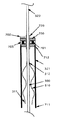
図1は本発明による吸痰管駆動装置及び吸痰装置の第1の実施例である。
患者1の気管2に装着された気管カニューレ200と気管カニューレの根元端202に接続された多分岐管410と図示されていない人工呼吸器400を接続する多分岐管の第1の根元側接続口412と該第1の根元側接続口412よりもさらに根元側の吸痰管待機位置で待機している状態の吸痰管の末端301が示されている。
FIG. 1 shows a first embodiment of a suction tube driving device and suction device according to the present invention.
A first root side connection port of a multi-branch tube connecting a
気管カニューレの根元端202には多分岐管の末端側接続口411が嵌合されている。多分岐管の第1の根元側接続口412には人工呼吸器400に連なる換気ホース413が接続されている。多分岐管の第2の根元側接続口414には本発明の吸痰管送り機構500の筐体550の末端側接続口510が嵌合されている。ピン511を多分岐管の第2の根元側接続口414のフランジ415に引っ掛けることによって、多分岐管の第2の根元側接続口414と筐体の末端側接続口510との嵌合が意図されずに引き離されることのないようになっている。
The distal
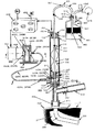
筐体550には2本のローラ520Aと520Bがそれぞれ2個のローラ軸受521Aと522A及び521Bと522Bに支持されて組み込まれている。図1では一揃いのみしか見えていないので、図1のA-A視図を図2に示した。
Two
図2で2本のローラ520Aと520Bは各々2個のローラ軸受521Aと522A及び521Bと522Bによって回動自在に保持されており、かつ各々2個のローラ軸受521Aと522A及び521Bと522Bの間に大径駆動部523Aと523Bを有している。該2個の大径駆動部523Aと523Bの間に吸痰管300を挟み込み,前記2本のローラ520Aと520Bを互いに逆方向に回転させることによって吸痰管300をその長手方向に駆動できるように構成されている。
In FIG. 2, two
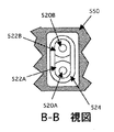
図3は図2のB-B視図であるが、前記ローラ軸受522Aと522Bの外輪は押さえ金524によって筐体550に固定されている。
3 is a view taken along the line B-B of FIG. 2, and the outer rings of the
図1に戻って、前記2本のローラ520Aと520Bを駆動するローラ駆動装置600について説明する。前記2本のローラ520Aと520Bは柔軟軸620Aと620Bによってそれぞれ駆動軸630Aと630Bとに結ばれている。柔軟軸620Aと620Bにはそれぞれ軸継ぎ手625Aと625Bが固着されており、軸継ぎ手625Aと625Bのローラ側はそれぞれローラ520A並びに520Bと着脱自在に結合できるように構成されており、使用時に柔軟軸620A並びに620Bとローラ520A並びに520Bとをそれぞれ繋合し、ローラ520A並びに520Bにトルクを伝える。
Returning to FIG. 1, a
駆動軸630Aと630Bは歯車箱640にそれぞれ2個の歯車軸受641Aと642A及び641Bと642Bを介して支えられ,該それぞれ2個の歯車軸受641Aと642A及び641Bと642Bの中間には互いにかみ合う歯車643A並びに643Bがスペーサ644Aと645A及び644Bと645Bを介して取り付けられている。
The
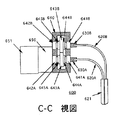
図1では柔軟軸、駆動軸及び歯車の一揃いしか見えていないので、図1のC-C視図を図4に示す。
図4で、駆動軸630Aは減速機650を介してモータ651に結合されている。モータ651の回転及びトルクは駆動軸630A側の歯車643Aに伝えられた後,直径及び歯数の等しい2個の歯車643Aと643Bの噛み合わせ機構によって,回転方向が互いに逆でトルクの大きさが等しい2個のトルクに分割され,それぞれ駆動軸630A並びに630Bから柔軟軸620A並びに620Bに出力される。
Since only one set of the flexible shaft, the drive shaft, and the gear is visible in FIG. 1, the CC view of FIG. 1 is shown in FIG.
In FIG. 4, the drive shaft 630 </ b> A is coupled to the
なお、駆動軸630Aとその歯車軸受け642Aは減速機650の軸を利用してもよい。
The
また柔軟軸620A並びに620Bは2本のチューブを一体に成形した並列導管621(図1では図示省略)のそれぞれのチューブに通され,上記トルクを受けて柔軟軸620A及び620Bが回転したときにお互いに絡み合わないようになっている。
The
図1に戻って、歯車箱640は患者1に影響を及ぼさない固定台652に静置される。
Returning to FIG. 1, the
図1において、前記筐体550のローラ520A並びに520Bよりもさらに根元側には,吸痰管300を貫通させる貫通口551、センサ支持体の末端側接続部711を連接するセンサ支持体取り付け部552及び防護袋の末端側接続口311を気密に嵌合する防護袋取り付け部553が設けられている。
In FIG. 1, a sensor
防護袋の根元側接続口312は吸痰管300に気密に接着されており、吸痰管300の挿抜に伴って、防護袋取り付け部553に接近、遠離し、同時に防護袋310は短縮、伸張する。
The protective bag root
センサ支持体の根元側接続部712には検出部700が固着されている。センサ支持体710は単数もしくは複数の薄い板で作られており、筐体550と検出部700との間隔を一定に保つとともに、横方向の剛性を低くし、かつ軽量にして患者1への負担を軽くしている。
The
検出部700には発光ダイオード701と受光フォトトランジスタ705が間に吸痰管300を挟んで相対して設けられており、吸痰管300の挿入限界マーク320及び抜き出し限界マーク321の通過を検出する。すなわち、通常は吸痰管300を透過した発光ダイオード701からの光を受光フォトトランジスタ705が受光しているが、挿入限界マーク320または抜き出し限界マーク321によって光が遮られると受光フォトトランジスタ705の出力がなくなるので、制御器800でその変化を検出してモータ651の動作を制御する。
The
制御器800は(1)手動抜き出しスイッチ810(手動抜き出しスイッチ810を押している間だけ吸痰管300を抜き出す方向にモータ651を駆動し、手動抜き出しスイッチ810を離すとモータ651が停止する)、(2)手動挿入スイッチ815(手動挿入スイッチ815を押している間だけ吸痰管300を挿入する方向にモータ651を駆動し、手動挿入スイッチ815を離すとモータ651が停止する)、(3)自動吸痰スイッチ820(自動吸痰スイッチ820を押すと、吸痰管300をその待機位置から挿入方向に送り、挿入限界マーク320が検出部700を通過したら一旦停止し、次に吸痰管300を逆に抜き出し方向に送り始めると同時に開閉弁1002を開いて吸引を開始する、抜き出し限界マーク321が検出部700を通過したら開閉弁1002を閉じて吸引を終了すると同時に一旦停止し、その後再度吸痰管300を挿入方向に送り、抜き出し限界マーク321が検出部700を通過したら停止して待機状態に入る)、(4)リセットスイッチ830(挿入限界マーク320と抜き出し限界マーク321の中間に検出部700があるとき、リセットスイッチ830を押すと、開閉弁1002の閉を確認して、吸痰管300を抜き出し方向に送り、抜き出し限界マーク321が検出部700を通過したら一旦停止し、その後再度吸痰管300を挿入方向に送り、抜き出し限界マーク321が検出部700を通過したら停止して待機状態に入る)、(5)緊急停止スイッチ840(緊急停止スイッチ840を押すと、ただちに開閉弁1002を閉鎖し、同時にモータ651を停止し、警報出力850を出力する。再度緊急停止スイッチ840を押すと、警報出力850の出力を停止し、さらにリセットスイッチ830を押したときと同じリセット動作を実行して待機状態に戻る)、の5種類のスイッチを備えている。
The controller 800 (1) manual extraction switch 810 (drives the
吸痰管の根元端302は接続管305を介して中継管330に接続され、さらに中継管330は気液分離瓶900の気液管340に接続され、さらに気液管340は気液分離瓶900内の気液分離液901中に開口している。一方、気液分離瓶の他端には吸引管1000が接続され、吸引管の末端1001は気液分離瓶900中の気液分離気体902中に開口している。吸引管1000は開閉弁1002を経て吸引源1010に接続されている。気液分離瓶900の栓910は気液管340及び吸引管1000を通すための気液管口911及び吸引管口912を持っており、かつ外径が先細のテーパになった弾性素材で作られた栓であって、周知の方法で気液分離瓶内と外気との導通を遮断する。
The
吸引源1010は病院に設備されている大型の集中吸引源を利用してもよいし,家庭用もしくは可搬型のいわゆる吸痰器でもよい。吸痰器が開閉弁を保有している場合には、開閉弁1002は該吸痰器の開閉弁を利用してもよい。
The
以上述べた第1の実施例において,図5に示したように吸痰管300、防護袋310及び吸痰管送り機構500(ローラ520A、520B、筐体の末端側接続口510及びピン511を含む)は一体組み立て品として製造し,滅菌処理後密封して供給する。該一体組み立て品を以後吸痰管駆動アセンブリ1100と称することにする。また、該吸痰管駆動アセンブリ1100に適合する多分岐管410は吸痰管駆動アセンブリよりも使用期間は長いもののいずれは廃棄すべき部品としてやはり滅菌処理後密封して供給する。
In the first embodiment described above, as shown in FIG. 5, the
つぎに、本実施例の動作を説明する。 Next, the operation of this embodiment will be described.
患者1が気管カニューレ200を取り付けた状態にあるとき、多分岐管の第2の根元側接続口414を図示していないキャップ416で塞いだ多分岐管410をその末端側接続口411で気管カニューレの根元端202に接続する。
When the patient 1 is attached with the
つぎに多分岐管の第1の根元側接続口412に人工呼吸器400の換気ホース413を接続し人工呼吸器による換気を行う。
Next, the
つぎに、患者1が人工呼吸器400を使用中で吸引源1010は多分岐管410には接続されていない状態のときに、多分岐管410に吸痰管駆動アセンブリ1100を装着し、自動吸痰作業開始が可能な待機状態に設定し、その後自動吸痰作業と待機状態への復帰とを繰り返し、最後に吸痰管駆動アセンブリ1100を多分岐管410から取り外して人工呼吸器400のみを使用している状態に戻すまでの一連の作業及び動作を例として説明する。
Next, when the patient 1 is using the ventilator 400 and the
患者1が人工呼吸器400を使用中で吸引源1010は多分岐管410には接続されていない状態のとき、気液分離瓶900には気液管340と吸引管1000とがそれぞれ気液管口911及び吸引管口912を通して栓910によって気密に取り付けられ、さらに気液管340には中継管330及び接続管305が接続されており、吸引管1000は開閉弁1002を介して吸引源1010に接続されている。また、開閉弁1002は閉じられ,多分岐管の第2の根元側接続口414は図示していないキャップ416によって塞がれている。
When the patient 1 is using the ventilator 400 and the
この状態から吸痰管駆動アセンブリ1100を装着するときは、次の手順で装着する。まず(1)吸痰管駆動アセンブリ1100を密閉袋から取り出し,(2)吸痰管300の根元端302をセンサ支持体710側から検出器700に通し、挿入限界マーク320が検出器700から外部に抜き出るまで根元端302を引き出し、(3)吸痰管300の根元端302を接続管305に接続し、次に、(4)センサ支持体の末端側接続部711を筐体550のセンサ支持体取り付け部552に取り付ける。さらに、(5)ローラ520A並びに520Bに柔軟軸620A並びに620Bの軸継ぎ手625A並びに625Bをそれぞれ接続する、(6)キャップ416をはずして多分岐管の第2の根元側接続口414を開口し、そこに(7)吸痰管300を吸痰管の末端301から挿入する、そして、(8)筐体の末端側接続口510を多分岐管の第2の根元側接続口414に嵌合し、(9)ピン511を押し込んでフランジ415に引っ掛け固定する。
When the suction
次に、手動抜き出しスイッチ810及び手動挿入スイッチ815の操作、あるいは手動で吸痰管300を出し入れして、検出部700が挿入限界マーク320と抜き出し限界マーク321の中間に来るようにする。
Next, the
次に、リセットスイッチ830を押して、吸痰管300を待機位置にセットする。リセットスイッチ830を押した後の制御器800の動作は、(1)まず開閉弁1002が閉じていることを確認し、(2)吸痰管300の抜き出し限界マーク321が検出部700に到達して発光ダイオード701から受光フォトトランジスタ705への光を遮り、次に抜き出し限界マーク321が検出部700を通過して再び発光ダイオード701から受光フォトトランジスタ705への光が遮られなくなるまで抜き出し方向に吸痰管300を送る。(3)抜き出し限界マーク321が検出部700を通過し終えたら直ちにモータ651を停止する。(4)次に吸痰管300を挿入方向に送り、抜き出し限界マーク321が検出部700を再び通過したら直ちにモータ651を停止する。以上の動作によって、吸痰管300は待機位置にセットされる。
Next, the
この状態において、吸痰管300の抜き出し限界マーク321は検出部700の末端側に位置し、吸痰管の末端301は予め設定されている気管カニューレ200の望ましい位置すなわち多分岐管の第1の根元側接続口412よりもさらに根元側の人工呼吸器400による換気を妨げない位置にセットされる。
In this state, the
患者1または介護者が制御器800の自動吸痰スイッチ820を押した後、あるいは患者1のモニタが吸引の必要を検出し、制御器800に自動吸痰開始を指令した後の制御器800の動作は、次の通りである。(1)まず吸痰管300を挿入方向に駆動する。(2)挿入限界マーク320が検出部700を通過したら、直ちにモータ651を停止する。挿入限界マーク320が検出部700を通過することは上記の抜き出し限界マーク321が検出部700を通過するのを検出したのと同じ方法で検出する。次に(3)吸痰管300を抜き出し方向に駆動すると同時に(4)開閉弁1002を開放し、吸引を開始する。(5)前記の方法で挿入限界マーク320が検出部700を通過するのを検出する。(6)さらに継続して吸痰管300を抜き出し方向に駆動する。(7)検出部700を抜き出し限界マーク321が通過したら、開閉弁1002を閉にすると同時に(8)モータ651を停止する。(9)再び吸痰管300を挿入方向に駆動し、抜き出し限界マーク321が検出部700を通過したら、モータ651を停止し、前記待機状態に戻る。この状態で次の自動吸痰開始指令まで待機する。
After the patient 1 or caregiver presses the
自動吸痰中の事態の急変に際して、緊急停止スイッチ840が押されると、制御器800は(1)直ちに開閉弁1002を閉にする、同時に(2)モータ651を停止し、(3)警報出力850を出力する。警報出力850によって、ブザーを鳴らしたり、警報ランプを点滅させたり、遠隔の介護者に警報を伝達したり、できる。また、(3)手動挿入スイッチ815及び自動吸痰スイッチ820を操作不能にして、制御器800からは吸痰管300を挿入方向には駆動できないようにする。
When the
緊急停止スイッチ840を再度押すと、(1)警報を停止する、(2)リセットスイッチ830を押したときと同じ動作によって、吸痰管300を待機状態にセットする、(3)手動挿入スイッチ815及び自動吸痰スイッチ820を操作可能にする。
When the
自動化吸痰器を取り外すときは、(1)目視またはリセットスイッチ830を押して、吸痰管300が待機位置にあり、開閉弁1002が閉であることを確認する、(2)ローラ520A並びに520Bから軸継ぎ手625A並びに625Bを外す、(3)ピン511を引き出して、筐体の末端側接続口510を多分岐管の第2の根元側接続口414からはずす、(4)吸痰管300の末端301を多分岐管の第2の根元側接続孔414から引き抜く、(5)多分岐管の第2の根元側接続口414をキャップ416で塞ぐ、(6)吸痰管の根元端302を接続管305から外す、(7)センサ支持体の末端側支持部711からセンサ支持体取り付け部552を取り外す、(8)吸痰管の根元端302を検出部700から引き抜く、手順で吸痰管駆動アセンブリ1100を取り外す。このことによって、患者からの自動化吸痰器の取り外しが完了する。
When removing the automated suction device, (1) Confirm that the
吸痰管駆動アセンブリ1100をしかるべく廃棄する。
Dispose of suction
以上説明した第1の実施例では上記した自動化吸痰器の取り外し手順の(8)項の作業時に吸痰管の根元端302の内部に付着した分泌物が漏れて検出部700に付着し、検出部700を繰り返し使用することへの障害になる可能性が残っている。
In the first embodiment described above, the secretion adhering to the inside of the
そこで第2の実施例では図6のように吸痰管300が検出部700を貫通する部分に防汚スリーブ720を設け、上記手順(8)項において、防汚スリーブ720を吸痰管の根元端302とともに検出部700から引き抜くことにより、検出部700への分泌物の付着を防いだ。
Therefore, in the second embodiment, as shown in FIG. 6, an
以上説明した第1及び第2の実施例では検出部700の繰り返し使用が可能であり、毎回廃棄する吸痰管駆動アセンブリ1100が簡略になるので運転経費を節減できる利点があるが、一方で、吸痰管駆動アセンブリ1100の取り付け手順の(2)項の作業「吸痰管300の根元端302をセンサ支持体710側から検出器700に通し、挿入限界マーク320が検出器700から外部に抜き出るまで根元端302を引き出す」及び(4)項の作業「センサ支持体の末端側接続部711を筐体550のセンサ支持体取り付け部552に取り付ける」作業が必要であり、取り付けの手間は煩雑になる。また、第1の実施例では検出部700と分泌物の接触の可能性も残る。
In the first and second embodiments described above, the
そこで、第3の実施例では図7に示したように吸痰管300、検出部700、センサ支持体710、防護袋310及び吸痰管送り機構500(ローラ520A、520B、筐体の末端側接続口510及びピン511を含む)を一体組み立て品として製造し,滅菌処理後密封して供給するようにした。要すれば、第1の実施例の吸痰管駆動アセンブリに検出部700及びセンサ支持体710をさらに付加した部品を一体組み立て品として製造するようにした。
Therefore, in the third embodiment, as shown in FIG. 7, the
この一体組み立て品を以後吸痰管駆動アセンブリ2型1110と称することにする。
第3の実施例における吸痰管駆動アセンブリ2型1110の取り付けでは、第1の実施例における吸痰管駆動アセンブリ1100の取り付けと比較して、検出部700に吸痰管300を通しその位置を調整すること、及びセンサ支持体の末端側接続部711を筐体550のセンサ支持体取り付け部552に取り付けることが不要になり、コンセント702に制御器800からのプラグ703を接続するだけでよい。また、検出部700を廃棄するので、検出部700への分泌物の付着を防ぐ必要がない。
This integrated assembly is hereinafter referred to as suction tube drive assembly type 2 1110.
In the attachment of the suction tube drive assembly 2 type 1110 in the third embodiment, the
以上説明した第1乃至第3の実施例では吸痰管300を駆動する大径駆動部523Aや523Bが吸痰管300に接触して痰で濡れると、両者の間の摩擦が減少し、大きな力で吸痰管300を挟まないと吸痰管300を駆動出来なくなり、吸痰管300の断面の減少を招く欠点があった。
In the first to third embodiments described above, when the large-
第4の実施例では大径駆動部523A及び523Bの外周に複数の針を植え込み、回転駆動時に針の先端が吸痰管300の壁面に食い込んで吸痰管300を駆動する構造とした。これによって、小さな力で吸痰管300を挟んでも、確実に吸痰管300を駆動出来るようになった。
In the fourth embodiment, a plurality of needles are implanted on the outer circumferences of the large-
1 患者
2 気管
200 気管カニューレ
201 気管カニューレの末端
202 気管カニューレの根元端
300 吸痰管
301 吸痰管の末端
302 吸痰管の根元端
305 接続管
310 防護袋
311 防護袋の末端側接続口
312 防護袋の根元側接続口
320 挿入限界マーク
321 抜き出し限界マーク
330 中継管
340 気液管
400 人工呼吸器
410 多分岐管
411 多分岐管の末端側接続口
412 多分岐管の第1の根元側接続口
413 換気ホース
414 多分岐管の第2の根元側接続口
415 フランジ
416 キャップ
500 吸痰管送り機構
510 筐体の末端側接続口
511 ピン
520A、520B ローラ
521A、521B、522A、522B ローラ軸受
523A、523B 大径駆動部
524 押さえ金
550 筐体
551 貫通口
552 センサ支持体取り付け部
553 防護袋取り付け部
600 ローラ駆動装置
620A、620B 柔軟軸
621 並列導管
625A、625B 軸継ぎ手
630A、630B 駆動軸
640 歯車箱
641A、641B、642A、642B 歯車軸受
643A、643B 歯車
644A、644B、645A、645B スペーサ
650 減速機
651 モータ
652 固定台
700 検出部
701 発光ダイオード
702 コンセント
703 プラグ
705 受光フォトトランジスタ
710 センサ支持体
711 センサ支持体の末端側接続部
712 センサ支持体の根元側接続部
720 防汚スリーブ
800 制御器
810 手動抜き出しスイッチ
815 手動挿入スイッチ
820 自動吸痰スイッチ
830 リセットスイッチ
840 緊急停止スイッチ
850 警報出力
900 気液分離瓶
901 気液分離液
902 気液分離気体
910 栓
911 気液管口
912 吸引管口
1000 吸引管
1001 吸引管の末端
1002 開閉弁
1010 吸引源
1100 吸痰管駆動アセンブリ
1110 吸痰管駆動アセンブリ2型
1 patient
2 trachea
200 Tracheal cannula
201 End of
644A, 644B, 645A,
1100 Suction tube drive assembly 1110 Suction tube drive assembly type 2
Claims (9)
A suction device that is attached to a tracheal cannula together with a ventilator and sucks and removes sputum, the suction tube drive assembly according to claim 5, the roller drive device according to claim 2, and the suction device according to claim 3. A suction device comprising: a tube position detection device; a suction device according to item 7; and a suction tube drive control device according to item 8.
Priority Applications (1)
| Application Number | Priority Date | Filing Date | Title |
|---|---|---|---|
| JP2004369640A JP2006174939A (en) | 2004-12-21 | 2004-12-21 | Phlegm aspiration tube driving device and phlegm aspirator |
Applications Claiming Priority (1)
| Application Number | Priority Date | Filing Date | Title |
|---|---|---|---|
| JP2004369640A JP2006174939A (en) | 2004-12-21 | 2004-12-21 | Phlegm aspiration tube driving device and phlegm aspirator |
Publications (2)
| Publication Number | Publication Date |
|---|---|
| JP2006174939A true JP2006174939A (en) | 2006-07-06 |
| JP2006174939A5 JP2006174939A5 (en) | 2008-04-17 |
Family
ID=36729582
Family Applications (1)
| Application Number | Title | Priority Date | Filing Date |
|---|---|---|---|
| JP2004369640A Pending JP2006174939A (en) | 2004-12-21 | 2004-12-21 | Phlegm aspiration tube driving device and phlegm aspirator |
Country Status (1)
| Country | Link |
|---|---|
| JP (1) | JP2006174939A (en) |
Cited By (20)
| Publication number | Priority date | Publication date | Assignee | Title |
|---|---|---|---|---|
| CN102198295A (en) * | 2011-05-11 | 2011-09-28 | 许庆林 | Nasotracheal phlegm sucker |
| CN105816925A (en) * | 2016-05-16 | 2016-08-03 | 西安交通大学第附属医院 | Phlegm suction robot |
| JP2017510311A (en) * | 2014-02-28 | 2017-04-13 | エルエムイーシーエー カンパニー リミテッド | Artificial intelligence suction device |
| CN106668962A (en) * | 2016-08-03 | 2017-05-17 | 西安交通大学 | Respiratory tract sputum automatic cleaning system and method |
| CN108992290A (en) * | 2018-09-07 | 2018-12-14 | 广东省中医院(广州中医药大学第二附属医院、广州中医药大学第二临床医学院、广东省中医药科学院) | Multifunction phlegm-aspiration rack |
| CN110220758A (en) * | 2019-06-15 | 2019-09-10 | 广州金域医学检验中心有限公司 | Sputum sample leaves and takes the method that mycobacterium tuberculosis is separated in cup and sputum |
| CN111514386A (en) * | 2020-05-03 | 2020-08-11 | 段捷 | Department of respiration is with electronic sputum aspirator that can avoid bacterial infection |
| CN112545899A (en) * | 2020-12-26 | 2021-03-26 | 黑龙江省医院 | Quick nursing lung-heat-clearing sputum discharging device for respiratory medicine |
| CN112852605A (en) * | 2021-01-28 | 2021-05-28 | 扬州大学附属医院 | Novel phlegm cultivation collector |
| CN113975493A (en) * | 2021-11-29 | 2022-01-28 | 四川省医学科学院·四川省人民医院 | Novel portable miniature sputum aspirator |
| CN114272455A (en) * | 2021-12-28 | 2022-04-05 | 中国科学院大学宁波华美医院 | Phlegm clearing auxiliary device |
| CN114392407A (en) * | 2022-02-08 | 2022-04-26 | 山东大学 | Drainage integration method and device for hepatobiliary surgery endoscopic operation |
| CN114588462A (en) * | 2022-03-02 | 2022-06-07 | 山东中医药大学附属医院 | Paediatrics respiratory track cleaning device |
| CN114699570A (en) * | 2022-03-24 | 2022-07-05 | 复旦大学附属华山医院 | Respiratory tract sputum suction device for infectious disease patient |
| CN114904073A (en) * | 2022-05-16 | 2022-08-16 | 南方医科大学南方医院 | Novel sputum suction and back patting integrated machine |
| CN114949515A (en) * | 2022-05-20 | 2022-08-30 | 无锡市第五人民医院 | Auxiliary sputum excretion breathing machine |
| CN115154786A (en) * | 2022-07-23 | 2022-10-11 | 江苏摩技医疗科技有限公司 | Vibration percussion type sputum remover with atomization effect and using method thereof |
| CN115920158A (en) * | 2023-02-21 | 2023-04-07 | 吉林大学 | Oral cavity and nasal cavity continuous sputum suction device based on EICU |
| CN116407694A (en) * | 2023-03-20 | 2023-07-11 | 上海市公共卫生临床中心 | Automatic change sputum aspirator |
| CN115154786B (en) * | 2022-07-23 | 2024-04-26 | 江苏摩技医疗科技有限公司 | Vibration percussion type sputum remover with atomization effect and use method thereof |
-
2004
- 2004-12-21 JP JP2004369640A patent/JP2006174939A/en active Pending
Cited By (26)
| Publication number | Priority date | Publication date | Assignee | Title |
|---|---|---|---|---|
| CN102198295A (en) * | 2011-05-11 | 2011-09-28 | 许庆林 | Nasotracheal phlegm sucker |
| JP2017510311A (en) * | 2014-02-28 | 2017-04-13 | エルエムイーシーエー カンパニー リミテッド | Artificial intelligence suction device |
| CN105816925A (en) * | 2016-05-16 | 2016-08-03 | 西安交通大学第附属医院 | Phlegm suction robot |
| CN106668962A (en) * | 2016-08-03 | 2017-05-17 | 西安交通大学 | Respiratory tract sputum automatic cleaning system and method |
| CN108992290A (en) * | 2018-09-07 | 2018-12-14 | 广东省中医院(广州中医药大学第二附属医院、广州中医药大学第二临床医学院、广东省中医药科学院) | Multifunction phlegm-aspiration rack |
| CN110220758A (en) * | 2019-06-15 | 2019-09-10 | 广州金域医学检验中心有限公司 | Sputum sample leaves and takes the method that mycobacterium tuberculosis is separated in cup and sputum |
| CN111514386A (en) * | 2020-05-03 | 2020-08-11 | 段捷 | Department of respiration is with electronic sputum aspirator that can avoid bacterial infection |
| CN112545899A (en) * | 2020-12-26 | 2021-03-26 | 黑龙江省医院 | Quick nursing lung-heat-clearing sputum discharging device for respiratory medicine |
| CN112852605A (en) * | 2021-01-28 | 2021-05-28 | 扬州大学附属医院 | Novel phlegm cultivation collector |
| CN113975493A (en) * | 2021-11-29 | 2022-01-28 | 四川省医学科学院·四川省人民医院 | Novel portable miniature sputum aspirator |
| CN113975493B (en) * | 2021-11-29 | 2023-06-30 | 四川省医学科学院·四川省人民医院 | Novel portable miniature sputum aspirator |
| CN114272455A (en) * | 2021-12-28 | 2022-04-05 | 中国科学院大学宁波华美医院 | Phlegm clearing auxiliary device |
| CN114272455B (en) * | 2021-12-28 | 2022-06-10 | 中国科学院大学宁波华美医院 | Phlegm clearing auxiliary device |
| CN114392407A (en) * | 2022-02-08 | 2022-04-26 | 山东大学 | Drainage integration method and device for hepatobiliary surgery endoscopic operation |
| CN114392407B (en) * | 2022-02-08 | 2022-09-09 | 山东大学 | Drainage integration method and device for hepatobiliary surgery endoscopic operation |
| CN114588462A (en) * | 2022-03-02 | 2022-06-07 | 山东中医药大学附属医院 | Paediatrics respiratory track cleaning device |
| CN114699570A (en) * | 2022-03-24 | 2022-07-05 | 复旦大学附属华山医院 | Respiratory tract sputum suction device for infectious disease patient |
| CN114699570B (en) * | 2022-03-24 | 2023-09-15 | 复旦大学附属华山医院 | Respiratory tract sputum aspirator for infectious disease patient |
| CN114904073A (en) * | 2022-05-16 | 2022-08-16 | 南方医科大学南方医院 | Novel sputum suction and back patting integrated machine |
| CN114949515A (en) * | 2022-05-20 | 2022-08-30 | 无锡市第五人民医院 | Auxiliary sputum excretion breathing machine |
| CN115154786A (en) * | 2022-07-23 | 2022-10-11 | 江苏摩技医疗科技有限公司 | Vibration percussion type sputum remover with atomization effect and using method thereof |
| CN115154786B (en) * | 2022-07-23 | 2024-04-26 | 江苏摩技医疗科技有限公司 | Vibration percussion type sputum remover with atomization effect and use method thereof |
| CN115920158A (en) * | 2023-02-21 | 2023-04-07 | 吉林大学 | Oral cavity and nasal cavity continuous sputum suction device based on EICU |
| CN115920158B (en) * | 2023-02-21 | 2023-05-12 | 吉林大学 | Continuous oral cavity and nasal cavity sputum aspirator based on EICU |
| CN116407694A (en) * | 2023-03-20 | 2023-07-11 | 上海市公共卫生临床中心 | Automatic change sputum aspirator |
| CN116407694B (en) * | 2023-03-20 | 2023-09-12 | 上海市公共卫生临床中心 | Automatic change sputum aspirator |
Similar Documents
| Publication | Publication Date | Title |
|---|---|---|
| JP2006174939A (en) | Phlegm aspiration tube driving device and phlegm aspirator | |
| JP4652397B2 (en) | Patient ventilation / aspiration system | |
| US20080023005A1 (en) | Intra-Tracheal Sputum Aspirating Apparatus | |
| JP5274554B2 (en) | Modular wound treatment device with releasable clip connection | |
| KR101548898B1 (en) | Sputum device, artificial respiration apparatus, and method for operating sputum device | |
| EP1219311B1 (en) | Canister | |
| JP5970448B2 (en) | Endotracheal tube having one or more blocking elements, blocking elements, and methods of using blocking elements | |
| JP2009022443A (en) | Insertion assisting device | |
| JP2008073060A (en) | Phlegm aspiration tube driving device and phlegm aspirator | |
| JPH0374584B2 (en) | ||
| CN204542986U (en) | A kind of sputum aspirator | |
| CN115463274A (en) | Automatic sputum suction device for remote control | |
| CN111388816A (en) | Sputum suction and liquid removal respirator | |
| US6527743B1 (en) | Surgical system pump and method therefor | |
| JP3652356B2 (en) | Ventilation system and tracheal cannula | |
| CN104548222A (en) | Sputum suction apparatus | |
| CN211382990U (en) | Department of respiration sputum cleaning and sterilizing device | |
| JP2002177378A (en) | Suction device for sputum in respiratory tract | |
| CN110960735A (en) | Sputum suction tube and visual sputum suction device | |
| CN213189444U (en) | Laryngoscope device | |
| CN210612590U (en) | Sputum suction tube and sputum aspirator with same | |
| CN214912145U (en) | Adjustable tracheal catheter sputum aspirator | |
| CN212592178U (en) | Stethoscope for pediatric internal medicine | |
| US20170021120A1 (en) | Systems, devices, and methods for automated endotracheal suctioning | |
| CA3219894A1 (en) | A urinary catheter system and method for self-catheterization and urine extraction |
Legal Events
| Date | Code | Title | Description |
|---|---|---|---|
| A521 | Written amendment |
Free format text: JAPANESE INTERMEDIATE CODE: A523 Effective date: 20071204 |
|
| A621 | Written request for application examination |
Free format text: JAPANESE INTERMEDIATE CODE: A621 Effective date: 20071204 |
|
| A521 | Written amendment |
Free format text: JAPANESE INTERMEDIATE CODE: A523 Effective date: 20080115 |
|
| A977 | Report on retrieval |
Free format text: JAPANESE INTERMEDIATE CODE: A971007 Effective date: 20090813 |
|
| A131 | Notification of reasons for refusal |
Free format text: JAPANESE INTERMEDIATE CODE: A131 Effective date: 20090825 |
|
| A02 | Decision of refusal |
Free format text: JAPANESE INTERMEDIATE CODE: A02 Effective date: 20100105 |