JP2006174409A - Doherty high efficient amplifier for high frequency and signal processing method thereof - Google Patents
Doherty high efficient amplifier for high frequency and signal processing method thereof Download PDFInfo
- Publication number
- JP2006174409A JP2006174409A JP2005249445A JP2005249445A JP2006174409A JP 2006174409 A JP2006174409 A JP 2006174409A JP 2005249445 A JP2005249445 A JP 2005249445A JP 2005249445 A JP2005249445 A JP 2005249445A JP 2006174409 A JP2006174409 A JP 2006174409A
- Authority
- JP
- Japan
- Prior art keywords
- signal
- input
- output
- amplifier
- level
- Prior art date
- Legal status (The legal status is an assumption and is not a legal conclusion. Google has not performed a legal analysis and makes no representation as to the accuracy of the status listed.)
- Pending
Links
Images


Abstract
Description
本発明は、マイクロ波通信等に用いる高周波用のドハティ型の高効率増幅器、およびそ
の信号処理方法に関する。
The present invention relates to a high-frequency Doherty high-efficiency amplifier used for microwave communication and the like, and a signal processing method thereof.
従来、高効率の増幅器を実現する手段として、リニア増幅を行うメインアンプと、高出
力になるとメインアンプのリニアリティが劣化するのを補正するためのピーキングアンプ
を組み合わせて用いるドハティ型高効率増幅器(以下、ドハティアンプと称する。)があ
る。小電力で大出力を得るためにマイクロ波等の高い周波数の増幅器でもドハティアンプ
は、使用され始めている(例えば、非特許文献1。)。
Conventionally, as a means to realize a highly efficient amplifier, a Doherty type high efficiency amplifier (hereinafter referred to as a combination of a main amplifier that performs linear amplification and a peaking amplifier that corrects the deterioration of the linearity of the main amplifier at high output) , Called Doherty amplifier). Doherty amplifiers have started to be used even in high frequency amplifiers such as microwaves in order to obtain a large output with low power (for example, Non-Patent Document 1).
図9は、従来のドハティアンプの機能構成を示すブロック図、図10は、ドハティアン
プの入出力特性を説明する図である。
以下、図9と図10を参照してドハティアンプの動作を説明する。
FIG. 9 is a block diagram illustrating a functional configuration of a conventional Doherty amplifier, and FIG. 10 is a diagram illustrating input / output characteristics of the Doherty amplifier.
Hereinafter, the operation of the Doherty amplifier will be described with reference to FIGS.
図9において、ドハティアンプは、メインアンプ100、ピーキングアンプ200、出
力負荷300、ドハティアンプに入力される信号をメインアンプ100とピーキングアン
プ200とに分配して出力する分配器400、バイアス制御器500とから構成されてい
る。
In FIG. 9, the Doherty amplifier includes a main amplifier 100, a peaking amplifier 200, an
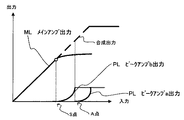
図10において、メインアンプ100とピーキングアンプ200の入力対出力の動作線
MLと動作線PLが描かれている。ピーキングアンプ200は、メインアンプ100の出
力の飽和が始まるS点から出力を開始する。
In FIG. 10, an input-to-output operation line ML and an operation line PL of the main amplifier 100 and the peaking amplifier 200 are drawn. The peaking amplifier 200 starts output from the point S where the saturation of the output of the main amplifier 100 starts.
バイアス制御器500は、ドハティアンプの入力信号レベルを観察し、入力信号レベル
がS点の入力レベルを越えると、ピーキングアンプ200にバイアス制御電圧を出力する
。そしてピーキングアンプ200は、メインアンプ100の出力低下を補って、出力負荷
300へ増幅信号を出力する。その結果、図2において点線部分で示される如く出力負荷
300ではメインアンプ100の出力と合成されたリニアな信号出力が得られるようにな
る(例えば、特許文献1。)。
The bias controller 500 observes the input signal level of the Doherty amplifier, and outputs a bias control voltage to the peaking amplifier 200 when the input signal level exceeds the input level at the point S. Then, the peaking amplifier 200 compensates for a decrease in the output of the main amplifier 100 and outputs an amplified signal to the
しかし、この補正方法に付いても、ピーキングアンプ200が動作を開始する入力レベ
ルSは、予め設定されたレベルであり、メインアンプ、およびピーキングアンプの利得や
メインアンプの飽和が始まる入力レベルが温度により変化したり、また、メインアンプ1
00の個体差もあり正確なリニア補正が出来ない問題があった。
There was a problem that accurate linear correction was not possible due to individual differences of 00.
従来の高周波用高効率増幅器は、ドハティアンプの入力信号レベルを監視してピーキン
グアンプの出力を制御するバイアス信号の電圧を調整するが、動作が温度変化の影響や、
アンプの個体差により、正確なリニアリティが得られない問題があった。
Conventional high-frequency high-efficiency amplifiers adjust the voltage of the bias signal that controls the output of the peaking amplifier by monitoring the input signal level of the Doherty amplifier.
There was a problem that accurate linearity could not be obtained due to individual differences of amplifiers.
本発明は上記問題を解決するためになされたもので、正確なリニアリティが得られる高
周波用の高効率増幅器、およびその信号処理方法を実現することを目的とする。
The present invention has been made to solve the above problems, and an object thereof is to realize a high-frequency high-efficiency amplifier capable of obtaining accurate linearity and a signal processing method thereof.
上記目的を達成するために、本発明の高周波用のドハティ型の高効率増幅器は、メイン
アンプとピーキングアンプとを有し、入力信号をリニアに増幅するメインアンプの出力と
、バイアス信号に制御されて前記入力信号から分配された信号を増幅して出力するピーキ
ングアンプの出力とを合成した出力信号を出力する高周波用のドハティ型の高効率増幅器
において、前記入力信号を検波して生成した入力レベル信号を出力する第1の検波器と、
前記合成された出力信号を検波して生成した出力レベル信号を出力する第2の検波器と、
前記入力レベル信号が一方の入力端子に入力され、前記出力レベル信号が他方の入力端子
に入力され、前記入力レベル信号および出力レベル信号を比較し、前記出力信号の前記入
力信号に対する利得が所定の値から低下した場合、前記利得を所定の値にするよう制御す
るバイアス信号を振幅制限器へ出力するレベル比較器と、前記レベル比較器から入力され
た前記バイアス信号の最高電圧を所定の電圧に制限して前記ピーキングアンプへ出力する
振幅制限器とを備えることを特徴とする。
In order to achieve the above object, the high-frequency Doherty high-efficiency amplifier of the present invention has a main amplifier and a peaking amplifier, and is controlled by the output of the main amplifier that linearly amplifies the input signal and the bias signal. In the high-frequency Doherty type high-efficiency amplifier that outputs an output signal obtained by combining the output of the peaking amplifier that amplifies and outputs the signal distributed from the input signal, the input level generated by detecting the input signal A first detector for outputting a signal;
A second detector for outputting an output level signal generated by detecting the synthesized output signal;
The input level signal is input to one input terminal, the output level signal is input to the other input terminal, the input level signal and the output level signal are compared, and the gain of the output signal with respect to the input signal is predetermined. A level comparator that outputs to the amplitude limiter a bias signal that controls the gain to a predetermined value, and a maximum voltage of the bias signal that is input from the level comparator is set to a predetermined voltage. And an amplitude limiter for limiting and outputting to the peaking amplifier.
また、本発明のメインアンプとピーキングアンプとを有し、入力信号をリニアに増幅す
るメインアンプの出力と、バイアス信号に制御されて前記入力信号から分配された信号を
増幅して出力するピーキングアンプの出力とを合成した出力信号を出力する高周波用のド
ハティ型の高効率増幅器の信号処理方法において、前記高効率増幅器は、メインアンプと
、ピーキングアンプと、第1の検波器と、第2の検波器と、レベル比較器と、振幅制限器
とを備え、前記第1の検波器は、前記入力信号を検波して生成した入力レベル信号を前記
レベル比較器の一方の入力端子に出力し、前記第2の検波器は、前記合成された出力信号
を検波して生成した出力レベル信号を前記レベル比較器の他方の入力端子に出力し、前記
入力レベル信号が一方の入力端子に入力され、前記出力レベル信号が他方の入力端子に入
力される前記レベル比較器は、前記入力レベル信号および出力レベル信号を比較し、前記
出力信号の前記入力信号に対する利得が所定の値から低下した場合、前記利得を所定の値
にするよう制御するバイアス信号を振幅制限器へ出力し、前記レベル比較器から前記バイ
アス信号が入力された前記振幅制限器は、前記入力された前記バイアス信号を所定の電圧
に制限して前記ピーキングアンプへ出力することを特徴とする高周波用のドハティ型の高
効率増幅器の信号処理方法。
In addition, the main amplifier and the peaking amplifier of the present invention, the output of the main amplifier that linearly amplifies the input signal, and the peaking amplifier that amplifies and outputs the signal distributed from the input signal controlled by the bias signal In the signal processing method for a high-frequency Doherty-type high-efficiency amplifier that outputs an output signal obtained by synthesizing the output of A detector, a level comparator, and an amplitude limiter, wherein the first detector outputs an input level signal generated by detecting the input signal to one input terminal of the level comparator; The second detector outputs an output level signal generated by detecting the synthesized output signal to the other input terminal of the level comparator, and the input level signal is input to one input terminal. The level comparator, to which the output level signal is input to the other input terminal, compares the input level signal with the output level signal, and the gain of the output signal with respect to the input signal decreases from a predetermined value. A bias signal for controlling the gain to a predetermined value is output to an amplitude limiter, and the amplitude limiter to which the bias signal is input from the level comparator outputs the bias signal to be input. A signal processing method for a high-efficiency Doherty-type high-efficiency amplifier, wherein the signal is output to the peaking amplifier while being limited to a predetermined voltage.
本発明によれば、ドハティ型高能率増幅器の入力と出力を比較し、利得が一定になるよ
うにピーキングアンプのバイアス信号の電圧を制御することにより正確なリニアリティを
持つ高周波用のドハティ型高効率増幅器を実現できる。
According to the present invention, the input and output of the Doherty type high efficiency amplifier are compared, and the voltage of the bias signal of the peaking amplifier is controlled so that the gain is constant, so that the Doherty type high efficiency for high frequency with accurate linearity is achieved. An amplifier can be realized.
以下、図面を参照して本発明の実施例を説明する。 Embodiments of the present invention will be described below with reference to the drawings.
図1は、本発明の実施例1に係るドハティ型高効率増幅器の機能構成を示すブロック図
、図2は、実施例1に係わるドハティ型高効率増幅器の入出力特性を説明する図である。
以下、図1と図2とを参照して、本発明の実施例に係わるドハティ型高効率増幅器(以
下、ドハティアンプと称する。)の構成と動作について説明する。
図1においてドハティアンプは、メインアンプ1、ピーキングアンプ2、分配器3、1
/4波長インピーダンス変換器4a、1/4波長インピーダンス変換器4b、バイアス制
御部5、遅延器10、および温度補償減衰器11から構成される。バイアス制御部5は、
検波器6、検波器7、レベル比較器8と、振幅制限器9とを備えている。また、入力、出
力にはそれぞれ信号をレベル比較器8へ分岐するためにカプラ21、カプラ22が設けら
れている。
FIG. 1 is a block diagram showing a functional configuration of a Doherty type high efficiency amplifier according to the first embodiment of the present invention, and FIG. 2 is a diagram for explaining input / output characteristics of the Doherty type high efficiency amplifier according to the first embodiment.
Hereinafter, the configuration and operation of a Doherty type high efficiency amplifier (hereinafter referred to as a Doherty amplifier) according to an embodiment of the present invention will be described with reference to FIGS.
In FIG. 1, a Doherty amplifier includes a
/ 4 wavelength impedance converter 4 a, ¼
A detector 6, a
本実施例1のドハティアンプでは、レベル比較器8が、入力と出力の信号レベルを比較
することによりドハティアンプの利得を調べる。そして、利得を一定、即ち、リニアリテ
ィを一定に保つバイアス信号をピーキングアンプに出力する。以下、構成各部の動作につ
いて説明する。
In the Doherty amplifier according to the first embodiment, the level comparator 8 checks the gain of the Doherty amplifier by comparing the input and output signal levels. Then, a bias signal that keeps the gain constant, that is, the linearity constant, is output to the peaking amplifier. Hereinafter, the operation of each component will be described.
メインアンプ1は、AB級などのリニアリティが良い動作の高出力アンプである。また
ピーキングアンプ2は、C級やD級などの高出力増幅器であり、信号入力端子に加えて動
作点を制御するバイアス信号Vggの入力端子を備えている。
The
ドハティアンプに入力される信号は、メインアンプ1とピーキングアンプ2の利得の温
度変化を補償する温度補償減衰器11を経て分配器3に入力される。そして入力された信
号は分配器3で2分され、一方は、メインアンプ1、他方は、ピーキングアンプ2に入力
される。メインアンプ1の出力端子は、1/4波長インピーダンス変換器4aを介してピ
ーキングアンプ2の出力端子へ接続される。ピーキングアンプ2の出力端子には、更に、
別の1/4波長インピーダンス変換器4bが接続され、ドハティアンプの外部へメインア
ンプ1とピーキングアンプ2とが増幅した信号が合成出力される。
A signal input to the Doherty amplifier is input to the distributor 3 through a temperature compensation attenuator 11 that compensates for a temperature change in the gain of the
Another quarter
また、入力された信号の一部がカプラ21で分岐して取り出され、遅延器10を介して
バイアス制御部5の検波器6へ出力される。検波器6は、入力信号を検波して、例えば、
直流信号に変換した入力レベル信号Viを生成してレベル比較器8の一方の入力端子へ出
力する。また、合成出力信号は、出力側のカプラ22で分岐され、バイアス制御部5の検
波器7で同様に出力レベル信号Voに変換されてレベル比較器8の他方の端子へ出力され
る。
In addition, a part of the input signal is branched out by the
An input level signal Vi converted into a DC signal is generated and output to one input terminal of the level comparator 8. The combined output signal is branched by the output-
ここでメインアンプ1は入力が小さい場合、リニア動作を行っているのでピーキングア
ンプ2は、カットオフ状態である。例えば、ピーキングアンプ2がFETにより構成され
ていれば、FETのドレイン電流が「0」になる様にバイアス制御部5からバイアス信号
Vggがピーキングアンプ2のFETのゲートに加えられている。そして、入力が大きく
なりメインアンプ1の出力が飽和し始めると、ピーキングアンプ2が動作を開始し、ドハ
ティアンプの出力がリニア、言い換えると利得が一定になる様に、バイアス制御部5がバ
イアス信号Vggの制御を行う。
Here, since the
レベル比較器8は、リニアリティを調べるために出力レベル信号Vo、および入力レベ
ル信号Viを測定し、所定の利得が劣化した場合(図2における出力が飽和を始めるS点
に相当。)、ピーキングアンプ2へ振幅制限器9を介してバイアス信号Vggを出力する
。この劣化を検出するため、例えば、利得が一定なところで、予め検波器7、検波器7か
ら供給される出力レベル信号Voとの入力レベル信号Viとが等しいレベルになる様、図
示されない減衰器等により調整される。そしてもし、メインアンプ1で飽和が発生すると
出力レベル信号Voは入力レベル信号Viよりも低い値になる。そして、レベル比較器8
は、その差を検出して出力および入力レベル信号Voと入力レベル信号Viとが等しくな
るよう、バイアス信号Vggをピーキングアンプ2へ振幅制限器9を介して出力する。
The level comparator 8 measures the output level signal Vo and the input level signal Vi to check the linearity, and when a predetermined gain is deteriorated (corresponding to the S point at which the output in FIG. 2 starts to be saturated), the peaking amplifier. 2 outputs the bias signal Vgg via the amplitude limiter 9. In order to detect this deterioration, for example, an attenuator (not shown) or the like is used so that the input level signal Vi and the output level signal Vo previously supplied from the
Detects the difference and outputs the bias signal Vgg to the peaking amplifier 2 via the amplitude limiter 9 so that the output and input level signal Vo and the input level signal Vi are equal.
そして、ピーキングアンプ2では、ゲートにバイアス信号Vggが加えられ、飽和した
メインアンプ1の出力を補うようにそれまでカットオフ状態であったドレイン電流が流れ
ることにより出力が始まる。その出力は、メインアンプ1の出力と合成され、レベル比較
器8が利得が一定になるようバイアス信号Vggの電圧を出力することによりドハティア
ンプのリニアリティが確保される。
In the peaking amplifier 2, the bias signal Vgg is applied to the gate, and the output starts when the drain current that has been in the cutoff state so far flows to compensate for the saturated output of the
なお、上記説明では、利得を一定にするため、レベル比較器8の両端子へのレベル信号
の入力電圧が等しくなるようにレベル比較器8がバイアス信号を制御するが、その他の利
得変化の測定方法、例えば、レベル比較器8が、両端子へ入力される両レベル信号を数値
化して比を算出してドハティアンプの利得を求め、その利得が一定になるようにバイアス
電圧を制御するものであっても良い。
In the above description, in order to make the gain constant, the level comparator 8 controls the bias signal so that the input voltages of the level signals to both terminals of the level comparator 8 are equal. Method, for example, the level comparator 8 calculates the ratio of both level signals inputted to both terminals and calculates the ratio to obtain the gain of the Doherty amplifier, and controls the bias voltage so that the gain becomes constant. There may be.
従来のドハティ型の高効率増幅器で行われる制御は、入力信号レベルだけを測定し、飽
和が始まると想定される入力信号レベルになるとピーキングアンプ2へ予め設定された補
償動作を行うバイアス信号を出力するオープンループ制御であることから、メインアンプ
1やピーキングアンプの動作が設定条件と異なる場合正確なリニアリティが確保出来なか
った。
The control performed by the conventional Doherty-type high-efficiency amplifier measures only the input signal level, and outputs a bias signal for performing a preset compensation operation to the peaking amplifier 2 when the input signal level is assumed to be saturated. Therefore, when the operation of the
さて、本実施例1では、更に振幅制限器9が追加されており、バイアス信号Vggの電
圧を監視して過入力が有った時にピーキングアンプ2が定格外の出力をしない様にバイア
ス信号Vggの最大値が制限される。このことにより、ピーキングアンプ2は保護される
と共に動作範囲が正確に設定され、その動作範囲でドハティアンプのリニアリティが正確
に保たれる効果がある。本発明の実施例1では、メインアンプの最大出力をMワット、ピ
ーキングアンプの最大出力をPワットとすれば、(M+P)ワットがドハティアンプの最
大出力となる。
In the first embodiment, an amplitude limiter 9 is further added to monitor the voltage of the bias signal Vgg and to prevent the peaking amplifier 2 from outputting an output that is not rated when there is an excessive input. The maximum value of is limited. As a result, the peaking amplifier 2 is protected and the operating range is accurately set, and the linearity of the Doherty amplifier is accurately maintained within the operating range. In
また、温度補償減衰器11は、メインアンプ1とピーキングアンプ2の利得などの温度
変化に対する動作変動を補償するために分配器3の入力側に設置されている。その結果、
利得変化の大きさや、出力飽和が開始する点の温度変動などが抑えられることによりピー
キングアンプ2への負担を減らすことが出来るので、不要な電源消費を防いでドハティア
ンプの安定性が向上する。
The temperature compensation attenuator 11 is installed on the input side of the distributor 3 in order to compensate for fluctuations in operation with respect to temperature changes such as the gain of the
Since the load on the peaking amplifier 2 can be reduced by suppressing the magnitude of the gain change and the temperature fluctuation at the point where the output saturation starts, unnecessary power consumption is prevented and the stability of the Doherty amplifier is improved.
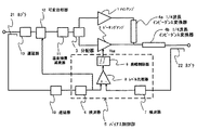
図3は、本発明の実施例2による高効率増幅器(ドハティアンプ)の機能構成を示すブ
ロック図、図4は、本発明の実施例2に係わるドハティアンプの入出力特性の関係を示す
図である。
図3において、ドハティアンプは、ピーキングアンプ2a、2b、またバイアス制御部
5がレベル比較器8a、8b、振幅制限器9a、9b、および1/4波長インピーダンス
変換器4cを備えている以外は、実施例1と同様である。
FIG. 3 is a block diagram showing a functional configuration of a high-efficiency amplifier (Doherty amplifier) according to Embodiment 2 of the present invention, and FIG. 4 is a diagram showing a relationship between input and output characteristics of the Doherty amplifier according to Embodiment 2 of the present invention. is there.
In FIG. 3, the Doherty amplifier has peaking
ピーキングアンプ2が2つになった場合、ピーキングアンプ2bに出力に接続される1
/4波長インピーダンス変換器4cは、ピーキングアンプ2aの1/4波長インピーダン
ス変換器4bの出力に更に追加され、ドハティアンプの出力はメインアンプ1と2つのピ
ーキングアンプ2a、2bとの合成出力になる。
When the number of peaking amplifiers 2 is two, the peaking amplifier 2b is connected to the
The / 4 wavelength impedance converter 4c is further added to the output of the quarter
実施例2では、合成出力が検波器7を介してレベル比較器8bに入力される。レベル比
較器8bは、メインアンプ1が飽和状態になるとゲート電圧Vggbを振幅制限器9bを
介してピーキングアンプ2bとレベル比較器8aの一方の入力端子とに出力する。
In the second embodiment, the combined output is input to the level comparator 8b via the
振幅制限器9bは、入力電圧が図4のA点に達するまでメインアンプ1の出力低下を補
うようにバイアス信号Vggbを出力する。ところが、A点でのピーキングアンプ2bの
出力(ここではPワットとする。)が、ピーキングアンプ2bの定格出力である場合、そ
れ以上の出力ではピーキングアンプ2は、飽和が発生し無駄な電力を消費するか、更には
故障する様になる。
The amplitude limiter 9b outputs the bias signal Vggb so as to compensate for the output drop of the
そこで、実施例1の如く、振幅制限器9bは、ピーキングアンプ2bのバイアス信号V
ggbが許容電圧(例えば、Xボルトとする。)を越えない様にXボルト一定の電圧を出
力するようになり、ピーキングアンプ2bの出力もPワットに保たれる。
Therefore, as in the first embodiment, the amplitude limiter 9b includes the bias signal V of the peaking amplifier 2b.
A constant voltage of X volts is output so that ggb does not exceed an allowable voltage (for example, X volts), and the output of the peaking amplifier 2b is also maintained at P watts.
然るに、本発明の実施例2では更に出力が必要な場合に備え、A点を超えても更に出力
を増せるように並列出力用のピーキングアンプ2aを備えている。
However, the second embodiment of the present invention is provided with a peaking
即ち、レベル比較器8aでは、レベル比較器8bからの、例えば、Yボルトの出力が一
方の入力端子へ入力され、他方の入力端子へは、振幅制限器9bの出力、最大Xボルトの
バイアス信号Vggbが比較入力として入力される。もし、ピーキングアンプ2bが定格
範囲内で動作するうちは、レベル比較器8bの2つの端子へ入力される各レベル信号の電
圧は、X=Yで等しい。そして、ドハティアンプの出力が大きくなりレベル比較器8bか
らの出力YボルトがXボルトを越えた場合、2つの入力される電圧の間に差が生じるので
レベル比較器8aは、入力される2つの電圧が等しくなるよう振幅制限器9aを介してピ
ーキングアンプ2aへバイアス信号Vggaを出力する。
That is, in the level comparator 8a, for example, the output of Y volts from the level comparator 8b is input to one input terminal, and the output of the amplitude limiter 9b and the bias signal of maximum X volts are input to the other input terminal. Vggb is input as a comparison input. If the peaking amplifier 2b operates within the rated range, the voltage of each level signal input to the two terminals of the level comparator 8b is equal to X = Y. When the output of the Doherty amplifier increases and the output Y volt from the level comparator 8b exceeds X volt, a difference occurs between the two input voltages, so the level comparator 8a A bias signal Vgga is output to the peaking
ピーキングアンプ2aと2bが同じ仕様のもので有れば、バイアス信号VggaとVg
gbの最大電圧は、同じXボルトであり振幅制限器9aの最大出力電圧もXボルトである
。そして、ピーキングアンプ2aは、ピーキングアンプ2bと同じく最大Pワットの出力
をする。そして、メインアンプ1とピーキングアンプ2a、2bの合計出力は(M+2P
)ワットとなる。
If the peaking
The maximum voltage of gb is the same X volt, and the maximum output voltage of the amplitude limiter 9a is also X volt. The peaking
) Watts.
一般に、大出力の半導体素子は、許容出力に反して応答速度が遅くなる欠点がある。実
施例2では、同仕様の小出力のピーキングアンプ2を並列使用することにより、応答速度
を落とさずに最大出力を増やすことができる効果がある。
In general, a high-power semiconductor device has a drawback that a response speed is slowed against an allowable output. In the second embodiment, there is an effect that the maximum output can be increased without reducing the response speed by using the small output peaking amplifier 2 of the same specification in parallel.
なお、ここでは2つのピーキングアンプ2を並列接続する場合を説明したが、更に複数
のピーキングアンプ2を並列接続する場合であっても、ピーキングアンプ2、レベル比較
器8、振幅制限器9の数を実施例2と同様に増やせば良く、その構成や動作は容易に推測
できるので説明は省略する。
Although the case where two peaking amplifiers 2 are connected in parallel has been described here, the number of peaking amplifiers 2, level comparators 8, and amplitude limiters 9 is the same even when a plurality of peaking amplifiers 2 are connected in parallel. May be increased in the same manner as in the second embodiment, and the configuration and operation thereof can be easily estimated, so that the description thereof is omitted.
以上、本発明の各実施例では、振幅のリニアリティが優れた高効率増幅器が実現できる
。実施例2では、小出力のピーキングアンプ2を並列使用することにより応答速度を高く
保つことが出来るドハティ型の高効率増幅器を実現している。
As described above, in each embodiment of the present invention, a high-efficiency amplifier having excellent amplitude linearity can be realized. In the second embodiment, a Doherty type high-efficiency amplifier capable of maintaining a high response speed is realized by using a small-output peaking amplifier 2 in parallel.
ところで、マイクロ波などの高周波では、応答速度のみならず、出力に応じて位相特性
が一定であることも重要である。そこで、本発明では、振幅特性だけでなく、出力振幅が
変化(言い換えれば入力振幅が変化)しても位相特性が同じ出力を得られるようにするこ
とが出来る。
By the way, at high frequencies such as microwaves, it is important that the phase characteristics are constant not only according to the response speed but also according to the output. Therefore, in the present invention, not only the amplitude characteristic but also the output having the same phase characteristic can be obtained even when the output amplitude changes (in other words, the input amplitude changes).
図5は、本発明の実施例3に係わるドハティ型高効率増幅器の機能ブロック図である。
図5において、ドハティアンプは、図1に示される実施例1のドハティアンプに、可変
位相器12、遅延器13、検波器14、およびカプラ23が追加されている以外は同じで
ある。
FIG. 5 is a functional block diagram of a Doherty type high efficiency amplifier according to Embodiment 3 of the present invention.
In FIG. 5, the Doherty amplifier is the same except that a
入力信号は、遅延器13を介して可変位相器12へ入力され、その可変位相器12の出
力が実施例1と同様のドハティアンプへ入力される。入力信号は、カプラ23により検波
器14へ分岐入力される。検波器14は、入力信号レベルに対応する直流の位相バイアス
信号、又は、入力レベル信号を生成して可変位相器12へ出力する。
The input signal is input to the
図6は、可変位相器12の内部機能構成を示すブロック図である。
図6において可変位相器12は、作動アンプ121、基準電圧器122と、位相調整器
123とを備えている。位相調整器123は、バイアス調整信号に対する位相特性が予め
知られており、また、入力信号レベルとドハティアンプの出力との間の位相特性も予め知
られ、この入力信号レベルから補正すべき位相を与えるバイアス調整信号が位相調整器1
23に加えられる。
FIG. 6 is a block diagram showing an internal functional configuration of the
In FIG. 6, the
23.
可変位相器12では、入力信号が位相調整器123の信号入力端子へ入力される。
In the
作動アンプ121の一方の入力端子に検波器23からの位相バイアス信号(入力レベル
信号)が入力される。そして、他方の入力端子に位相調整器123に所定の位相差を与え
るのに必要な基準電圧器122により設定された基準電圧が、入力される。この設定され
る位相は、例えば、最大入力信号レベルの時のドハティアンプの位相特性に揃えられる。
The phase bias signal (input level signal) from the detector 23 is input to one input terminal of the operational amplifier 121. Then, the reference voltage set by the reference voltage device 122 necessary to give a predetermined phase difference to the
作動アンプ121は、この基準電圧と入力される位相バイアス信号の差が最小になるよ
うにバイアス調整信号を位相調整器123に出力することにより、ドハティアンプの出力
は、入力信号のレベルにかかわらず一定の位相特性を持つようになる。
The operational amplifier 121 outputs a bias adjustment signal to the
図7は、位相調整を行うドハティアンプをより少ない構成で実現する場合の機能構成の
ブロック図である。
FIG. 7 is a block diagram of a functional configuration when the Doherty amplifier that performs phase adjustment is realized with a smaller configuration.
図5では、位相調整の為に専用に設けられた検波器14から可変位相器12へ位相バイ
アス信号、又は、入力レベル信号が出力されているが、図7におけるドハティアンプは、
可変位相器12へ供給される位相バイアス信号に、検波器6の出力の入力レベル信号を利
用している。
In FIG. 5, a phase bias signal or an input level signal is output from the
An input level signal output from the detector 6 is used as the phase bias signal supplied to the
図8は、本発明のドハティ型高効率増幅器の実施例4に係わる機能構成のブロック図で
ある。
図8において、ドハティアンプの位相特性を揃える為に、合成出力に位相検波器15を
接続し、その位相信号を位相バイアス信号として可変位相器12へ接続しているフィード
バック制御を行っている。図5、および図7に示される実施例3のドハティアンプでは、
入力信号を測定し、その入力信号のレベルに対応した位相補正の為のバイアスを位相調整
器123へ加えているオープンループの位相補正を行っている。これに対して実施例4で
は、入力信号のレベル測定は行わず、ドハティアンプの出力の位相特性を位相検波器15
を用いて測定して、予め設定された基準位相との間の誤差信号を直流の位相バイアス信号
として可変位相器123へ出力して、フィードバックしている。
FIG. 8 is a block diagram of a functional configuration according to the fourth embodiment of the Doherty type high efficiency amplifier of the present invention.
In FIG. 8, in order to align the phase characteristics of the Doherty amplifier, feedback control is performed in which a phase detector 15 is connected to the combined output and the phase signal is connected to the
The input signal is measured, and an open loop phase correction is performed in which a bias for phase correction corresponding to the level of the input signal is applied to the
The error signal between the reference phase and a preset reference phase is output to the
フィードバック制御により、振幅特性のリニアリティと共に入力信号レベルに位相特性
が左右されないドハティアンプが実現できる。
By feedback control, it is possible to realize a Doherty amplifier in which the phase characteristic is not affected by the input signal level as well as the linearity of the amplitude characteristic.
実施例3、4におけるドハティアンプの位相補償方法は、実施例2の様な複数のピーキ
ングアンプを用いる場合にも同様に適用可能である。
The phase compensation method of the Doherty amplifier in the third and fourth embodiments can be similarly applied to the case of using a plurality of peaking amplifiers as in the second embodiment.
以上、説明した如く、本発明により利得のリニアリティが良いドハティ型高効率増幅器
を実現することが出来、実施例3および4における如く、利得特性だけでなく入力信号の
レベル変化に対しても出力の位相特性が変化しないドハティ型高効率増幅器を実現するこ
とが出来る。
As described above, a Doherty type high efficiency amplifier with good gain linearity can be realized according to the present invention. As in the third and fourth embodiments, not only the gain characteristic but also the output of the output signal is changed not only with respect to the level change of the input signal. A Doherty-type high-efficiency amplifier whose phase characteristics do not change can be realized.
1 メインアンプ
10、13 遅延器
11 温度補償減衰器
12 可変位相器
121 差動アンプ
122 基準電圧器
123 位相調整器
15 位相検波器
2 ピーキングアンプ
21、22、23 カプラ
3 分配器
4a、4b、4c 1/4波長インピーダンス変換器
5 バイアス制御部
6、7、14 検波器
8、8a、8b レベル比較器
9、9a、9b 振幅制限器
DESCRIPTION OF
Claims (6)
の出力と、バイアス信号に制御されて前記入力信号から分配された信号を増幅して出力す
るピーキングアンプの出力とを合成した出力信号を出力する高周波用のドハティ型の高効
率増幅器において、
前記入力信号を検波して生成した入力レベル信号を出力する第1の検波器と、
前記合成された出力信号を検波して生成した出力レベル信号を出力する第2の検波器と、
前記入力レベル信号が一方の入力端子に入力され、前記出力レベル信号が他方の入力端子
に入力され、前記入力レベル信号および出力レベル信号を比較し、前記出力信号の前記入
力信号に対する利得が所定の値から低下した場合、前記利得を所定の値にするよう制御す
るバイアス信号を振幅制限器へ出力するレベル比較器と、
前記レベル比較器から入力された前記バイアス信号の最高電圧を所定の電圧に制限して前
記ピーキングアンプへ出力する振幅制限器とを
備えることを特徴とする高周波用のドハティ型の高効率増幅器。 It has a main amplifier and a peaking amplifier, and combines the output of the main amplifier that linearly amplifies the input signal and the output of the peaking amplifier that amplifies and outputs the signal distributed from the input signal under the control of the bias signal. In high-frequency Doherty type high-efficiency amplifier that outputs the output signal
A first detector for outputting an input level signal generated by detecting the input signal;
A second detector for outputting an output level signal generated by detecting the synthesized output signal;
The input level signal is input to one input terminal, the output level signal is input to the other input terminal, the input level signal and the output level signal are compared, and the gain of the output signal with respect to the input signal is predetermined. A level comparator that outputs a bias signal to the amplitude limiter for controlling the gain to a predetermined value when the value drops from the value;
A Doherty-type high-efficiency amplifier for high frequency, comprising: an amplitude limiter that limits a maximum voltage of the bias signal input from the level comparator to a predetermined voltage and outputs the same to the peaking amplifier.
の出力と、前記入力信号からそれぞれに分配された信号をそれぞれがバイアス信号に制御
されることにより増幅して出力する複数のピーキングアンプの各出力とを合成した出力信
号を出力する高周波用のドハティ型の高効率増幅器において、
前記入力信号を検波して生成した入力レベル信号を出力する第1の検波器と、
前記合成された出力信号を検波して生成した出力レベル信号を出力する第2の検波器と、
前記入力レベル信号が一方の入力端子に入力され、前記出力レベル信号が他方の入力端子
に入力され、前記入力レベル信号および出力レベル信号を比較し、前記出力信号の前記入
力信号に対する利得が所定の値から低下した場合、前記利得を所定の値にするよう制御す
る第1のバイアス信号を第2のレベル比較器の一方の入力端子と第1の振幅制限器とへ出
力する第1のレベル比較器と、
前記第1のレベル比較器から入力された前記第1のバイアス信号の最高電圧を所定の電圧
に制限して第1の前記ピーキングアンプと前記第2のレベル比較器の他方の入力端子とへ
出力する前記第1の振幅制限器と、
前記第1のレベル比較器から出力された第1の一方の入力端子に入力され、前記前記第1
の振幅制限器を介して前記第1のバイアス信号が他方の入力端子に入力され、前記両入力
端子に入力される各バイアス信号の電圧を比較し、前記各バイアス信号の電圧が等しくな
る様制御する第2のバイアス信号を第2の振幅制限器へ出力する第2のレベル比較器と、
前記入力された前記第2のバイアス信号を所定の最高電圧に制限して第2の前記ピーキン
グアンプへ出力する前記第2の振幅制限器とを
備えることを特徴とする高周波用のドハティ型の高効率増幅器。 A plurality of main amplifiers and peaking amplifiers that amplify the input signal linearly and amplify and output the signals distributed from the input signal by controlling each of them with a bias signal In the high-frequency Doherty type high-efficiency amplifier that outputs an output signal that is synthesized with each output of the peaking amplifier of
A first detector for outputting an input level signal generated by detecting the input signal;
A second detector for outputting an output level signal generated by detecting the synthesized output signal;
The input level signal is input to one input terminal, the output level signal is input to the other input terminal, the input level signal and the output level signal are compared, and the gain of the output signal with respect to the input signal is predetermined. A first level comparison that outputs a first bias signal for controlling the gain to a predetermined value to one input terminal of the second level comparator and the first amplitude limiter when the gain decreases from the value; And
The highest voltage of the first bias signal input from the first level comparator is limited to a predetermined voltage and output to the first peaking amplifier and the other input terminal of the second level comparator. Said first amplitude limiter;
Input to the first one input terminal output from the first level comparator;
The first bias signal is input to the other input terminal via the amplitude limiter, and the voltages of the bias signals input to the two input terminals are compared, and control is performed so that the voltages of the bias signals are equal. A second level comparator that outputs a second bias signal to the second amplitude limiter;
And a second amplitude limiter for limiting the input second bias signal to a predetermined maximum voltage and outputting the second bias signal to a second peaking amplifier. Efficiency amplifier.
する減衰特性を有する温度補償減衰器を更に備え、
前記メインアンプおよび前記ピーキングアンプは、前記温度補償器を介して前記入力信号
が入力されることを特徴とする請求項1又は2に記載の高効率増幅器。 A temperature compensation attenuator having an attenuation characteristic for compensating a temperature vs. gain characteristic of the main amplifier and the peaking amplifier set in advance;
The high-efficiency amplifier according to claim 1, wherein the input signal is input to the main amplifier and the peaking amplifier via the temperature compensator.
される入力レベル信号により前記メインアンプおよび前記ピーキングアンプの入力信号レ
ベルに対する対位相特性変動を補償する可変位相器を更に備え、
前記メインアンプおよび前記ピーキングアンプは、前記可変位相器を介して前記入力信号
が入力されることを特徴とする請求項1又は2に記載の高効率増幅器。 Variation in phase characteristics with respect to input signal levels of the main amplifier and the peaking amplifier by an input level signal output from the first detector or a third detector provided before the first detector Further comprising a variable phase shifter for compensating
The high-efficiency amplifier according to claim 1, wherein the input signal is input to the main amplifier and the peaking amplifier via the variable phase shifter.
前記メインアンプおよび前記ピーキングアンプは、前記可変位相器を介して前記入力信号
が入力され、
前記位相検波器は、前記合成された出力信号の位相を測定し基準となる位相との間の差を
示す誤差電圧を位相バイアス信号として前記可変位相器へ出力し、
前記可変位相器は、
前記位相バイアス信号により前記出力信号の位相を予め定められた位相に調整するフィー
ドバック制御を行うことを特徴とする請求項1又は2に記載の高効率増幅器。 The high efficiency amplifier further includes a phase detector and a variable phase shifter,
The main amplifier and the peaking amplifier receive the input signal via the variable phase shifter,
The phase detector measures the phase of the combined output signal and outputs an error voltage indicating a difference from a reference phase to the variable phase shifter as a phase bias signal,
The variable phase shifter is
3. The high efficiency amplifier according to claim 1, wherein feedback control is performed to adjust a phase of the output signal to a predetermined phase by the phase bias signal.
の出力と、バイアス信号に制御されて前記入力信号から分配された信号を増幅して出力す
るピーキングアンプの出力とを合成した出力信号を出力する高周波用のドハティ型の高効
率増幅器の信号処理方法において、
前記高効率増幅器は、メインアンプと、ピーキングアンプと、第1の検波器と、第2の検
波器と、レベル比較器と、振幅制限器とを備え、
前記第1の検波器は、前記入力信号を検波して生成した入力レベル信号を前記レベル比較
器の一方の入力端子に出力し、
前記第2の検波器は、前記合成された出力信号を検波して生成した出力レベル信号を前記
レベル比較器の他方の入力端子に出力し、
前記入力レベル信号が一方の入力端子に入力され、前記出力レベル信号が他方の入力端子
に入力される前記レベル比較器は、
前記入力レベル信号および出力レベル信号を比較し、前記出力信号の前記入力信号に対す
る利得が所定の値から低下した場合、前記利得を所定の値にするよう制御するバイアス信
号を振幅制限器へ出力し、
前記レベル比較器から前記バイアス信号が入力された前記振幅制限器は、
前記入力された前記バイアス信号を所定の電圧に制限して前記ピーキングアンプへ出力す
る
ことを特徴とする高周波用のドハティ型の高効率増幅器の信号処理方法。 It has a main amplifier and a peaking amplifier, and combines the output of the main amplifier that linearly amplifies the input signal and the output of the peaking amplifier that amplifies and outputs the signal distributed from the input signal under the control of the bias signal. In a signal processing method for a high-efficiency Doherty-type high-efficiency amplifier that outputs the output signal,
The high efficiency amplifier includes a main amplifier, a peaking amplifier, a first detector, a second detector, a level comparator, and an amplitude limiter.
The first detector outputs an input level signal generated by detecting the input signal to one input terminal of the level comparator,
The second detector outputs an output level signal generated by detecting the synthesized output signal to the other input terminal of the level comparator,
The level comparator in which the input level signal is input to one input terminal and the output level signal is input to the other input terminal,
The input level signal and the output level signal are compared, and when the gain of the output signal with respect to the input signal decreases from a predetermined value, a bias signal for controlling the gain to a predetermined value is output to the amplitude limiter. ,
The amplitude limiter to which the bias signal is input from the level comparator,
A signal processing method for a high-frequency Doherty type high-efficiency amplifier, characterized in that the input bias signal is limited to a predetermined voltage and output to the peaking amplifier.
Priority Applications (1)
| Application Number | Priority Date | Filing Date | Title |
|---|---|---|---|
| JP2005249445A JP2006174409A (en) | 2005-08-30 | 2005-08-30 | Doherty high efficient amplifier for high frequency and signal processing method thereof |
Applications Claiming Priority (1)
| Application Number | Priority Date | Filing Date | Title |
|---|---|---|---|
| JP2005249445A JP2006174409A (en) | 2005-08-30 | 2005-08-30 | Doherty high efficient amplifier for high frequency and signal processing method thereof |
Related Parent Applications (1)
| Application Number | Title | Priority Date | Filing Date |
|---|---|---|---|
| JP2004359705A Division JP4387936B2 (en) | 2004-12-13 | 2004-12-13 | Doherty type high efficiency amplifier for high frequency and signal processing method thereof |
Publications (1)
| Publication Number | Publication Date |
|---|---|
| JP2006174409A true JP2006174409A (en) | 2006-06-29 |
Family
ID=36674622
Family Applications (1)
| Application Number | Title | Priority Date | Filing Date |
|---|---|---|---|
| JP2005249445A Pending JP2006174409A (en) | 2005-08-30 | 2005-08-30 | Doherty high efficient amplifier for high frequency and signal processing method thereof |
Country Status (1)
| Country | Link |
|---|---|
| JP (1) | JP2006174409A (en) |
Cited By (6)
| Publication number | Priority date | Publication date | Assignee | Title |
|---|---|---|---|---|
| JP2008131186A (en) * | 2006-11-17 | 2008-06-05 | Hitachi Kokusai Electric Inc | Power amplifier |
| JP2009010515A (en) * | 2007-06-26 | 2009-01-15 | Panasonic Corp | Predistortion type distortion compensation amplifier |
| KR100895532B1 (en) | 2008-10-24 | 2009-04-30 | 주식회사 엠텍아이앤씨 | Highly efficient digital pre-distortion amplifier |
| JP2010226190A (en) * | 2009-03-19 | 2010-10-07 | Fujitsu Ltd | Amplifying device and transmission apparatus |
| US8847681B2 (en) | 2009-10-23 | 2014-09-30 | Ngk Insulators, Ltd. | Combiner for Doherty amplifier |
| JP2015126447A (en) * | 2013-12-26 | 2015-07-06 | 古河電気工業株式会社 | Amplification device and failure detection method for the same |
-
2005
- 2005-08-30 JP JP2005249445A patent/JP2006174409A/en active Pending
Cited By (7)
| Publication number | Priority date | Publication date | Assignee | Title |
|---|---|---|---|---|
| JP2008131186A (en) * | 2006-11-17 | 2008-06-05 | Hitachi Kokusai Electric Inc | Power amplifier |
| JP2009010515A (en) * | 2007-06-26 | 2009-01-15 | Panasonic Corp | Predistortion type distortion compensation amplifier |
| KR100895532B1 (en) | 2008-10-24 | 2009-04-30 | 주식회사 엠텍아이앤씨 | Highly efficient digital pre-distortion amplifier |
| JP2010226190A (en) * | 2009-03-19 | 2010-10-07 | Fujitsu Ltd | Amplifying device and transmission apparatus |
| US8847681B2 (en) | 2009-10-23 | 2014-09-30 | Ngk Insulators, Ltd. | Combiner for Doherty amplifier |
| JP5705122B2 (en) * | 2009-10-23 | 2015-04-22 | 日本碍子株式会社 | Doherty amplifier synthesizer |
| JP2015126447A (en) * | 2013-12-26 | 2015-07-06 | 古河電気工業株式会社 | Amplification device and failure detection method for the same |
Similar Documents
| Publication | Publication Date | Title |
|---|---|---|
| JP4387936B2 (en) | Doherty type high efficiency amplifier for high frequency and signal processing method thereof | |
| KR101092681B1 (en) | Power amplifier controller circuit | |
| US8095090B2 (en) | RF power amplifier controller circuit | |
| US7777566B1 (en) | Amplifier compression adjustment circuit | |
| KR101709347B1 (en) | A combined cell doherty power amplify apparatus and method | |
| JP4849573B2 (en) | RF power amplifier controller circuit with compensation for output impedance mismatch | |
| JP4792273B2 (en) | amplifier | |
| JP2009260658A (en) | Power amplifier | |
| JP2006174409A (en) | Doherty high efficient amplifier for high frequency and signal processing method thereof | |
| US9577586B1 (en) | Feed reflected Doherty amplifier and method for driving Doherty amplifiers | |
| JP6103035B2 (en) | Power amplifier, failure detection method | |
| JP2009303040A (en) | High-frequency power amplifier and amplification method | |
| WO2015029462A1 (en) | Power amplification device and control method for power amplification device | |
| KR101021471B1 (en) | Dynamic Doherty Power Amplifier | |
| JP5010542B2 (en) | High frequency power amplifier and amplification method | |
| JP2005151185A (en) | Method for synthesizing high output wideband signal, and amplifier | |
| JP4259143B2 (en) | Feed forward amplifier |
Legal Events
| Date | Code | Title | Description |
|---|---|---|---|
| A621 | Written request for application examination |
Free format text: JAPANESE INTERMEDIATE CODE: A621 Effective date: 20070228 |
|
| A131 | Notification of reasons for refusal |
Free format text: JAPANESE INTERMEDIATE CODE: A131 Effective date: 20090731 |
|
| A02 | Decision of refusal |
Free format text: JAPANESE INTERMEDIATE CODE: A02 Effective date: 20091204 |