JP2006171069A - Fixing device and image forming apparatus - Google Patents
Fixing device and image forming apparatus Download PDFInfo
- Publication number
- JP2006171069A JP2006171069A JP2004359593A JP2004359593A JP2006171069A JP 2006171069 A JP2006171069 A JP 2006171069A JP 2004359593 A JP2004359593 A JP 2004359593A JP 2004359593 A JP2004359593 A JP 2004359593A JP 2006171069 A JP2006171069 A JP 2006171069A
- Authority
- JP
- Japan
- Prior art keywords
- belt
- roller
- pressure
- fixing
- fixing device
- Prior art date
- Legal status (The legal status is an assumption and is not a legal conclusion. Google has not performed a legal analysis and makes no representation as to the accuracy of the status listed.)
- Granted
Links
Images


Abstract
Description
本発明は、シート上にトナー画像を定着する定着装置、及びこれを備えた画像形成装置に関する。 The present invention relates to a fixing device that fixes a toner image on a sheet, and an image forming apparatus including the same.
電子写真装置、静電記録装置などの画像形成装置においては、シート上にトナー画像を転写し、これを定着させることにより画像を形成している。未定着トナー画像を加熱溶融して定着する定着装置として、内部にヒータを有する定着ローラに加圧ローラを圧接してニップを形成し、定着を行うローラ定着方式が一般的である。 In an image forming apparatus such as an electrophotographic apparatus or an electrostatic recording apparatus, an image is formed by transferring a toner image onto a sheet and fixing it. As a fixing device for fixing an unfixed toner image by heating and melting, a roller fixing system is generally used in which a pressure roller is pressed against a fixing roller having a heater therein to form a nip, and fixing is performed.
ところで高光沢な画像を出力するためには、シートのニップ通過時間を長くし、トナーを充分に溶融する必要がある。このときローラ定着方式では、ニップを広げようとするとローラ径を大きくしなければならず、装置が大きなものになってしまう。また、ローラ回転速度を遅くすることで、トナーを充分に溶融することができるが、それでは高速化が困難である。 By the way, in order to output a highly glossy image, it is necessary to lengthen the sheet nip passing time and sufficiently melt the toner. At this time, in the roller fixing method, if the nip is to be widened, the roller diameter must be increased, and the apparatus becomes large. Further, the toner can be sufficiently melted by reducing the roller rotation speed, but it is difficult to increase the speed.
そこで、ローラ定着方式に対して、装置の小型化、高速化対応を達成しつつ、充分な圧接部の幅(搬送方向の長さ)が得られる上下ベルト定着方式が特許文献1(特開平11−174878)や特許文献2(特開平05−072926)で提案されている。これらの提案においては、定着装置は2つの対向するベルト部材を備え、これらベルト部材によって挟持搬送することにより、大きな圧接部の幅を得ている。 In view of this, an upper and lower belt fixing method that can achieve a sufficient width (length in the conveying direction) of the press contact portion while achieving a reduction in the size and speed of the apparatus with respect to the roller fixing method is disclosed in Japanese Patent Application Laid-Open No. 11-151867. -174878) and Patent Document 2 (Japanese Patent Laid-Open No. 05-072926). In these proposals, the fixing device includes two opposing belt members, and a large width of the press contact portion is obtained by sandwiching and conveying these belt members.
しかしながら、特許文献1や特許文献2で開示されている定着装置は、圧接部内において、支持部材同士で加圧している圧の高い部分と、ベルトの両側から何も支持されていない圧の抜けた部分が存在する。このため、未定着トナー画像を定着しようとする場合、圧の高い部分と抜けた部分とで、シートに搬送速度差が発生する。ベルト部材はある程度の可撓性を有するものであるから、搬送速度差によってベルトが伸縮し、シート上の画像がずれるという問題が発生する。また、圧抜け部では、トナー層中の空気及び水蒸気を抑え込めなくなるので、特にコート紙等の通気性の低いシートにおいては、画像の乱れが発生しやすくなる。
However, in the fixing devices disclosed in
そこで本発明は、定着装置の圧接部内における圧力分布を改善することにより、小型であるのに高速定着が可能で、画ズレを防止できる定着装置、及びこれを備えた画像形成装置を提供することを目的としている。 SUMMARY OF THE INVENTION Accordingly, the present invention provides a fixing device capable of high-speed fixing and preventing image misalignment, and an image forming apparatus provided with the fixing device, by improving the pressure distribution in the pressure contact portion of the fixing device. It is an object.
上記課題を解決するために、本発明に係る定着装置の代表的な構成は、シート上の画像をニップにて熱定着する第1のベルトと、前記第1のベルトを張架する第1のローラと、前記第1のベルトとの間で前記ニップを形成する第2のベルトと、前記第1のローラに対向して設けられ前記第2のベルトを張架する第2のローラと、前記第1のベルトを内面から前記第2のベルトに向けて加圧する第1の加圧部材と、前記第2のベルトを内面から前記第1のベルトに向けて加圧する第2の加圧部材と、を有する定着装置において、前記第1の加圧部材を前記第2の加圧部材に対しシート搬送方向にずらして配置し、且つ、前記第1のローラを前記第2のローラに対しシート搬送方向にずらして配置することで、前記第1の加圧部材、前記第2の加圧部材、前記第1のローラ、前記第2のローラによって前記ニップを連続的に形成したことを特徴とする。 In order to solve the above problems, a typical configuration of a fixing device according to the present invention includes a first belt that thermally fixes an image on a sheet at a nip, and a first belt that stretches the first belt. A second belt that forms the nip between the roller and the first belt, a second roller that is provided opposite to the first roller and stretches the second belt, and A first pressure member that pressurizes the first belt from the inner surface toward the second belt; and a second pressure member that pressurizes the second belt from the inner surface toward the first belt; In the fixing device, the first pressure member is arranged so as to be shifted in the sheet conveyance direction with respect to the second pressure member, and the first roller is conveyed with respect to the second roller. By disposing in the direction, the first pressure member and the second pressure member Member, wherein the first roller, characterized in that the formation of the nip by said second roller continuously.
本発明によれば、定着装置にベルトを用いた場合において、2つ以上の支持部材の隙間に対向する加圧手段から加圧している。従って、ベルトを用いたことにより圧接部の幅を飛躍的に増大させることができ、高速化した場合においても高光沢な画像が出力可能である。また同時に、圧抜け部が存在せず、画ズレの発生を防止することができる。 According to the present invention, when a belt is used in the fixing device, the pressure is applied from the pressure unit facing the gap between the two or more support members. Accordingly, the use of the belt can dramatically increase the width of the press contact portion, and a high gloss image can be output even when the speed is increased. At the same time, there is no pressure loss portion, and the occurrence of image misalignment can be prevented.
以下に、実施例を挙げて、本発明をより具体的に説明する。なお、これら実施例は、本発明における最良の実施の形態の一例ではあるものの、本発明はこれら実施例により限定されるものではない。 Hereinafter, the present invention will be described more specifically with reference to examples. Although these examples are examples of the best mode of the present invention, the present invention is not limited to these examples.
{第一実施例}
本発明に係る定着装置および画像形成装置の第一実施例について説明する。まず図6を用いて、画像形成装置の全体構成について説明する。
{First Example}
A first embodiment of a fixing device and an image forming apparatus according to the present invention will be described. First, the overall configuration of the image forming apparatus will be described with reference to FIG.
図6に示す画像形成装置は、電子写真方式を採用した画像形成装置(いわゆるプリンタ)である。 The image forming apparatus shown in FIG. 6 is an image forming apparatus (so-called printer) that employs an electrophotographic system.
画像形成装置1は、潜像を担持する像担持体の例としての感光体ドラム2を備えている。感光体ドラム2は帯電器3によって一様に帯電され、光学装置4から光5を照射されることにより潜像が形成される。潜像はこれを現像する現像手段の例としての現像器6によって現像され、トナー画像が形成される。トナー画像は転写手段の例としての転写ローラ7によってシートに転写され、感光体ドラム2上に残留したトナーはクリーニング装置8によって除去される。
The
シートSは装置下部の給送カセット9に備えられており、給送ローラ10によって給送される。シートは搬送手段の例としてのレジストローラ対11によって感光体ドラム2上の画像と同期して搬送され、トナー画像を転写された後に、定着装置Aへと搬送される。そしてシートSは、定着装置Aにおいて加熱、加圧されることによってトナー画像を定着され、排出ローラ対12によって装置上部の排出トレイ13へと排出、積載される。
The sheet S is provided in a feeding cassette 9 at the lower part of the apparatus, and is fed by a
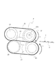
図1は本実施例に係る定着装置Aの断面図、図2は比較例を説明する断面図である。図に示すように、定着装置Aは、第1のベルトの例としての定着ベルト20と、第2のベルトの例としての加圧ベルト21とを備えている。定着ベルト20は内径が34mmで、厚みが75μmのポリイミドを基層とし、基層の外周には弾性層として耐熱性シリコーンゴム層が300μmの厚みで設けられている。このシリコーンゴムは、JIS-A20度の硬度を持ち、熱伝導率は0.8W/mKである。更に弾性層の外周には、表面離型層としてフッ素樹脂層(例えばPFAやPTFE)が30μmの厚みで設けられる。加圧ベルト21は内径が34mmで、厚みが75μmのポリイミドを基層とし、表面は離型層としてフッ素樹脂であるPFAチューブを30μmの厚みで設けられている。
FIG. 1 is a cross-sectional view of a fixing device A according to this embodiment, and FIG. 2 is a cross-sectional view illustrating a comparative example. As shown in the figure, the fixing device A includes a
定着ベルト20は、定着ローラ22と加圧ローラ23(第1のローラ)によって張架されている。定着ローラ22は、外径が20mmで、内径が18mmである厚さ1mmの鉄製の中空ローラであり、内部に加熱手段の例としてのハロゲンヒータ22aを配置している。加圧ローラ23は、外径が20mmで、径が16mmである鉄合金製の芯金に、熱伝導率を小さくして定着ベルト20からの熱伝導を少なくするためにシリコーンゴムスポンジ層が設けてある。長手方向中央部での加圧ローラ23の硬度はASK-C硬度計で約60度である。また、定着ベルト20の回転は、加圧ローラ23を図示しないモーターによって駆動し、加圧ローラ23のシリコーンゴムスポンジ表面と定着ベルト20の内面ポリイミド層との摩擦によって駆動する。
The
定着ローラ22と加圧ローラ23との間には、定着ベルト20を支持する第1の加圧部材の例としての加圧パッド24が、これらのローラからそれぞれ約1mmの距離をあけて近接配置されている。加圧パッド24は弾性体であって、厚さ3mm、幅8mmの耐熱性シリコーンゴムから構成されており、定着ベルト20に対して擦動自在に固定配置されている。
Between the
加圧ベルト21は、圧接部の上流側に配置された加圧ローラ25と、下流側に配置された加圧ローラ26(第2のローラ)によって張架されている。圧接部の上流側に配置された加圧ローラ25は、定着ベルト20内に配置された加圧ローラ23と同じものであり、外径が20mmで、径が16mmである鉄合金製の芯金に、熱伝導率を小さくして定着ベルト20からの熱伝導を少なくするためにシリコーンゴムスポンジ層を設けてある。圧接部の下流側に配置された加圧ローラ26は、外径が20mmで、厚みが1.0mmである鉄合金製である芯金に、厚みが0.3mmのシリコーンゴム層が設けてある。すなわち、加圧ローラ26は対向する加圧ローラ23よりも、高い剛性に構成されている。
The
加圧ローラ25と加圧ローラ26の間には、加圧ベルト21を支持する第2の加圧部材の例としての加圧パッド27が、これらのローラから約1mmの距離をあけて近接配置されている。加圧パッド27は加圧パッド24と同様に弾性体であって、厚さ3mm、幅8mmの耐熱性シリコーンゴムから構成されており、加圧ベルト21に対して擦動自在に固定配置されている。
Between the
定着ベルト20は、少なくとも画像形成実行時には、駆動手段(不図示)によって加圧ローラ23が回転駆動されることで、図1の矢印X方向に回転駆動される。定着ベルト20の周速度は、画像転写部側から搬送されてくるシートSの搬送速度とほぼ同一である。加圧ベルト21は、定着ベルト20に従動するか、または同一の周速度となるように加圧ローラ26を駆動されることにより、矢印Y方向に回転する。本実施例の場合、定着ベルト20の表面回転速度が300mm/secで回転し、A4サイズのフルカラーの画像を1分間に70枚定着することが可能である。
The
定着ベルト20が所定の定着温度に立ち上がって温調された状態において、圧接部における定着ベルト20と加圧ベルト21との間(圧接部)に、未定着トナー画像Tを有するシートSが搬送される。シートSは、未定着トナー画像を担持した面を、定着ベルト20側に向けて導入される。そしてシートSの未定着トナー画像側が定着ベルト20の外周面に密着し、定着ベルト20と一緒に圧接部を挟持搬送されていくことにより、主に定着ベルト20の熱が付与され、また圧接部の加圧力を受けて未定着トナー画像TがシートSの表面に熱圧定着される。
In a state where the fixing
また、定着ベルト20内の加圧ローラ23に比べて加圧ベルト21内の下流に位置する加圧ローラ26の方が剛性が高いので、定着ベルト20と加圧ベルト21との圧接部出口では加圧ローラ23の変形が大きくなり、結果として定着ベルト20も大きく変形し、トナー画像が定着ベルト20から自己分離して良好にシートを分離搬送できる。
Further, since the
ここで、加圧ベルト21内部の支持部材としては、定着ローラ22、加圧ローラ23、加圧パッド24が該当する。また、定着ローラ22内部の支持部材としては、加圧ローラ25、加圧ローラ26、加圧パッド27が該当する。これらは近接配置されているとはいえ、それぞれの隙間を対向させて配置してしまうと、圧力抜け部が発生することとなる。
Here, as the support member inside the
そこで本実施例においては、ほぼ対象の支持部材配置となっている定着ベルト20と加圧ベルト21とを、搬送方向に所定量ずらして配置している。これにより、加圧ベルト21の下流側の加圧ローラ26は、定着ベルト20の加圧ローラ23と加圧パッド24との隙間に対向し、ここを加圧するよう配置されている。本実施例では、加圧ローラ26は加圧ローラ23と加圧パッド24の両方を加圧するように配置されている。
Therefore, in the present embodiment, the fixing
同様に、定着ベルト20の上流側の加圧パッド24は、加圧ベルト21の加圧ローラ26と加圧パッド27の隙間に加圧するように配置される。すなわち加圧パッド24は、加圧ローラ26と加圧パッド27の両方を加圧するように配置されている。
Similarly, the
また加圧ベルト21の加圧パッド27は、定着ベルト20の定着ローラ22と加圧パッド24の隙間に加圧するように配置される。すなわち加圧パッド27は、定着ローラ22と加圧パッド24の両方を加圧するように配置されている。
Further, the
さらに定着ベルト20の定着ローラ22は、加圧ベルト21の加圧ローラ25と加圧パッド27との隙間に加圧するように配置される。すなわち定着ローラ22は、加圧ローラ25と加圧パッド27の両方を加圧するように配置されている。
Further, the fixing
このように構成した定着装置Aは、定着ベルト20と加圧ベルト21との圧接部のベルト回転方向の幅(搬送方向の長さ)は約25mmになる。この幅が広いので、高速に搬送しても十分な定着を行うことが可能になる。
In the fixing device A configured as described above, the width in the belt rotation direction (length in the transport direction) of the pressure contact portion between the fixing
また、定着ベルト20または加圧ベルト21の一方の内部の支持部材の隙間に対し、他方の内部の支持部材が加圧するよう構成したことにより、圧力抜けが発生しない。従って、幅の広い圧接部でありながら搬送速度差が発生することなく、画ズレが発生することがない。本実施例の構成において、通気性の低いコート紙での画ズレ発生の有無を確認したところ、画ズレは発生しなかった。
Further, since the other supporting member is pressed against the gap between the supporting members inside one of the fixing
さらに、加圧パッド24、27を弾性体にて構成していることから、ニップ内の圧力は定着ローラ23と加圧ローラ26との対向部にて最大となる。これにより、上下のローラでそれぞれのベルトを駆動すれば、両方のベルトともスリップ無く安定して回転させることができる。
Further, since the
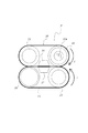
一方、図2に示すのは、定着ローラ22と加圧ローラ25、加圧パッド24と加圧パッド27、加圧ローラ23と加圧ローラ26をそれぞれ対向させた比較例である。従って図2に示す定着装置A’の構成では、支持部材の隙間が対向しており、この部分において圧抜け部が存在する。この比較例においてコート紙を通紙したところ、画ズレの発生が確認された。
On the other hand, FIG. 2 shows a comparative example in which the fixing
なお、本実施例においては定着ベルト20を加圧ベルト21に対して搬送方向下流側にずらすよう説明したので、加圧パッド27、加圧パッド24、加圧ローラ26、加圧ローラ23の順にニップを連続的に形成している。しかし定着ベルト20を搬送方向上流側にずらしてもよく、その場合は加圧パッド24、加圧パッド27、加圧ローラ23、加圧ローラ26の順にニップが連続的に形成される。
In the present embodiment, the fixing
{第二実施例}
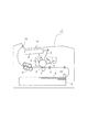
本発明に係る定着装置および画像形成装置の第二実施例について説明する。図3は本実施例に係る定着装置Bを説明する図、図4は比較例を説明する図である。上記第一実施例と説明の重複する部分については、同一の符号を付して説明を省略する。本実施例において画像形成装置1には、上記の定着装置Aに代えて、次に説明する定着装置Bが備えられている。
{Second Example}
A second embodiment of the fixing device and the image forming apparatus according to the present invention will be described. FIG. 3 is a diagram illustrating a fixing device B according to the present embodiment, and FIG. 4 is a diagram illustrating a comparative example. The same parts as those in the first embodiment are denoted by the same reference numerals and the description thereof is omitted. In this embodiment, the
定着装置Bにおける第1のベルトの例としての定着ベルト30は、内径が34mmで電気鋳造法によって製造したニッケルを基層とし、基層の厚みは50μmである。基層の外周には弾性層として耐熱性シリコーンゴム層が300μmの厚みで設けられている。このシリコーンゴムは、JIS-A20度の硬度を持ち、熱伝導率は0.8W/mKである。更に弾性層の外周には、表面離型層としてフッ素樹脂層(例えばPFAやPTFE)が30μmの厚みで設けられる。基層の内面には、後述するベルトガイド部材32との摺動摩擦を低下させるために、フッ素樹脂やポリイミドなどの樹脂層を10〜50μm設けても良い。本実施例では、ポリイミドを20μm設けた。また、定着ベルト30内面が接する内包物が導電性の場合は、定着ベルト基層金属層に有効に誘導電流を流すために、定着ベルト30内面には電気絶縁層が有ることが望ましい。なお、定着ベルト30はニッケルのほかに鉄合金や銅、銀など適宜選択可能である。また、樹脂基層にそれら金属を積層させるなどの構成でも良い。金属層の厚みは、後で説明する誘導加熱コイルに流す高周波電流の周波数と金属層の透磁率、導電率に応じて調整して良く、5〜200μm程度の間で設定する。
The fixing
定着装置Bにおける第2のベルトの例としての加圧ベルト31は、内径が34mmで、厚みが75μmのポリイミドを基層とし、表面は離型層としてフッ素樹脂であるPFAチューブを30μmの厚みで設けた。後述するベルトガイド部材33との摺動摩擦を低下させるために、基層であるポリイミドにフッ素樹脂の微粒子を分散させておくと良い。
The
定着ベルト30は、ベルトガイド部材32と加圧ローラ34によって支持されている。
The fixing
ベルトガイド部材32は弾性を有する樹脂製であり本実施例ではPPS製(ポリフェニレンサルファイド樹脂)である。ベルトガイド部材32は定着ベルト30に対して約49Nの張力を与えており、定着ベルト30の内面と接する部分にはリブが設けてある。リブは、ベルトガイド部材32が定着ベルト30の内面と接触する面積を減らして、摩擦抵抗を減らすために設けてある。また、定着ベルト30の内面と接触する面積を減らして、加熱した定着ベルト30からの熱の伝導を減少させて効率よく定着ベルト30のみを高温に保つためでもある。ただし、定着ベルト30と加圧ベルトの圧接部でベルトガイド部材32によって加圧されるので、ベルトガイド部材32の圧接部にはリブがない。
The
固定部材であるベルトガイド部材32を用いることで、回転するローラの場合よりもベルト内面からの伝熱量を減少させることができ、ウオーミングアップタイムが短縮される。これは、固定されているガイド部材に比べ、回転するローラの場合は、ベルト内面と接触している時にベルト内面からローラ表面に吸熱、回転することでベルト内面から離れた時に放熱、また回転後にベルト内面から吸熱というサイクルを繰り返すのため、ベルト内面からの伝熱量が増えてしまうためである。
By using the
また、ベルトガイド部材32を用いることで、ローラとパッドの2部材を連続的に配置することができるので、圧抜け部が発生しない。
In addition, by using the
加圧ローラ34は、外径が20mmで、長手方向中央部の径が16mmで両端部の径が14mmである鉄合金製の芯金に、熱伝導率を小さくして定着ベルト30からの熱伝導を少なくするためにシリコーンゴムスポンジ層が設けてある。長手方向中央部での加圧ローラ34の硬度はASK-C硬度計で約60度である。芯金にテーパー形状をつけているのは、加圧した時に加圧ローラ34が撓んでも加圧ローラ35との圧接部の幅が長手方向にわたって均一となるようにするためである。ベルトガイド部材32と加圧ローラ34間は約1mmの距離をあけて近接配置されている。また、定着ベルト30の回転は、加圧ローラ34を図示しないモーターによって駆動し、加圧ローラ34のシリコーンゴムスポンジ表面と定着ベルト30の内面ポリイミド層との摩擦によって定着ベルト30は回転する。
The
加圧ベルト31は、ベルトガイド部材33と加圧ローラ35によって支持されている。
The
ベルトガイド部材33は弾性を有する樹脂製であり本実施例ではPPS製である。ベルトガイド部材33は加圧ベルト31に対して約49Nの張力を与えており、加圧ベルト31の内面と接する部分にはリブが設けてある。リブは、ベルトガイド部材33が加圧ベルト31の内面と接触する面積を減らして、摩擦抵抗を減らすために設けてある。ただし、定着ベルト30と加圧ベルト31の圧接部でベルトガイド部材33によって加圧されるので、圧接部のベルトガイド部材33にはリブがない。
The
固定部材であるベルトガイド部材33を用いることで、ローラとパッドの2部材を連続的に配置することができるので、圧抜け部が発生しない。
By using the
加圧ローラ35は、外径が20mmで、厚みが1.0mmである鉄合金製である芯金に、厚みが0.3mmのシリコーンゴム層が設けてある。ベルトガイド部材33と加圧ローラ35間は約1mmの距離をあけて近接配置されている。加圧ベルト31の回転は、加圧ローラ35を図示しないモーターによって駆動し、加圧ローラ35のシリコーンゴム表面と加圧ベルト31のポリイミド層との摩擦によって加圧ベルト31は回転する。
In the
このように構成した定着装置Bは、定着ベルト30と加圧ベルト31との圧接部のベルト回転方向の幅(搬送方向の長さ)は約25mmになる。この幅が広いので、高速に搬送しても十分な定着を行うことが可能になる。
In the fixing device B configured as described above, the width in the belt rotation direction (length in the conveying direction) of the pressure contact portion between the fixing
また、ベルトガイド部材33はベルトガイド部材32に向かって約98Nで、加圧ローラ35は加圧ローラ34に向かって約294Nで加圧されている。このとき、圧接部におけるベルトガイド部材32、33の対よりもローラ対34、35の位置のほうが単位面積あたりの圧力が高いので、上下のローラでそれぞれのベルトを駆動すれば、両方のベルトともスリップ無く安定して回転させることができる。
The
また、加圧ローラ34に比べて加圧ローラ35の方が硬いので、定着ベルト30と加圧ベルト31との圧接部出口では加圧ローラ34の変形が大きくなり、結果として定着ベルト30も大きく変形し、トナー画像が自己分離して良好にシートを定着ベルト30から分離、搬送できる。
Further, since the
定着ベルト30の加熱源としての誘導加熱コイル36は、誘導加熱コイル36によって発生した磁界が定着ベルト30の金属層以外に漏れないように磁性体コア37で覆われており、更に電気絶縁性の樹脂によって、誘導加熱コイル36と磁性体コア37は一体でモールドされている。定着ベルト30と誘導加熱コイル36は0.5mmのモールドにより電気絶縁の状態を保ち、定着ベルト30と誘導加熱コイル36との間隔は1.5mm(モールド表面と定着ベルト表面の距離は1.0mm)で一定であり、定着ベルト30は均一に加熱される。誘導加熱コイル36は、シートSの通紙幅方向(シートSの搬送方向に直交する方向)に沿っての長さが、画像形成に供される最大通紙幅のシートSのその通紙幅よりも長くなるように形成されている。上述の誘導加熱コイルには、20〜50kHzの高周波電流が流されて、定着ベルト30の金属層が誘導発熱し、定着ベルト30の目標温度である170℃で一定になるように、温度センサの検出値に基づいて高周波電流の周波数を変化させて誘導加熱コイル36に入力する電力を制御して温度調節される。加圧ローラ34のシリコーンゴムスポンジ層は最も薄いところでも2mmあり、誘導加熱コイル36によって芯金が発熱することはほとんどないので、本実施例では効率よく定着ベルト30のみを加熱することができる。温度センサはベルトガイド部材32に取り付けられており、定着ベルト30の内面の誘導加熱コイル36による発熱量が最も高い位置に接触しており、その部分の温度を検出している。
The
定着ベルト30は、少なくとも画像形成実行時には、不図示の駆動手段によって加圧ローラ34が回転駆動されることで、矢印X方向に回転駆動される。加圧ベルト31も同様に、不図示の駆動手段によって加圧ローラ35が回転駆動されることで、矢印Y方向に回転駆動される。これらの周速度は、画像転写部側から搬送されてくるシートSの搬送速度とほぼ同一である。本実施例の場合、定着ベルト30と加圧ベルト31の表面回転速度が300mm/secで回転し、A4サイズのフルカラーの画像を1分間に70枚定着することが可能である。
The fixing
また、定着ベルト30が所定の定着温度に立ち上がって温調された状態において、圧接部における定着ベルト30と加圧ベルト31との間(圧接部)に、未定着トナー画像Tを有するシートSが搬送される。シートSは、未定着トナー画像を担持した面を、定着ベルト30側に向けて導入される。そしてシートSの未定着トナー画像側が定着ベルト30の外周面に密着し、定着ベルト30と一緒に圧接部を挟持搬送されていくことにより、主に定着ベルト30の熱が付与され、また圧接部の加圧力を受けて未定着トナー画像TがシートSの表面に熱圧定着される。
Further, in a state where the fixing
加圧ベルト31は不図示のカムによって、定着ベルト30に対して離接するように移動可能である。この機構によって、定着動作時以外は加圧ベルト31は定着ベルト30と離間した状態になっている。こうすることで定着ベルト30の熱が加圧ベルト31に伝導しないので、定着装置Bのウォーミングアップタイムは、加圧ベルト31が定着ベルト30から離間している状態だと、例えば誘導加熱コイル36に1200W入力すると約18秒で目標温度である170℃に到達できる。
The
ここで、定着ベルト30内部の支持部材としては、ベルトガイド部材32、加圧ローラ34が該当する。また、加圧ベルト31内部の支持部材としては、ベルトガイド部材33、加圧ローラ35が該当する。これらは近接配置されているとはいえ、それぞれの隙間を対向させて配置してしまうと、圧力抜け部が発生することとなる。
Here, the
そして本実施例においては、ほぼ対象の支持部材配置となっている定着ベルト30と加圧ベルト31とを、搬送方向に所定量ずらして配置している。これにより、加圧ベルト31の加圧ローラ35は、定着ベルト30のベルトガイド部材32と加圧ローラ34の隙間に対向し、ここを加圧するよう配置されている。本実施例では、加圧ローラ35はベルトガイド部材32と加圧ローラ34の両方を加圧するように配置されている。
In this embodiment, the fixing
また同時に、定着ベルト30のベルトガイド部材32は、ベルトガイド部材33と加圧ローラ35の隙間を加圧するように配置されている。すなわちベルトガイド部材32は、ベルトガイド部材33と加圧ローラ35の両方を加圧するように配置されている。
At the same time, the
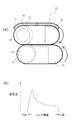
このように定着ベルト30または加圧ベルト31の一方の内部の支持部材の隙間に対し、他方の内部の支持部材が加圧するよう構成したことにより、圧力抜けが発生しない。図3(b)に示すのは本実施例の構成における圧接部での加圧力分布であり、大きな圧抜け部が存在せず、上流側から徐々に圧力が高くなっていることがわかる。従って、幅の広い圧接部でありながら搬送速度差が発生することなく、画ズレが発生することがない。本実施例の構成において、通気性の低いコート紙での画ズレ発生の有無を確認したところ、画ズレは発生しなかった。
As described above, since the support member in the other side pressurizes the gap between the support members in one side of the fixing
一方、図4(a)に示すのは、ベルトガイド部材32、33、および加圧ローラ34、35をそれぞれ対向させた比較例である。従って図4(a)に示す定着装置B’の構成では、支持部材の隙間が対向している。図4(b)に示すのは本比較例の構成における圧接部での加圧力分布であり、支持部材の隙間が対向した部分において、大きな圧抜け部が存在することがわかる。この比較例において通気性の低いコート紙を通紙したところ、画ズレの発生が確認された。
On the other hand, FIG. 4A shows a comparative example in which the
以上説明したように、本実施例においては、定着ベルトおよび加圧ベルトを加圧ローラとベルトガイドによって支持することで、小径で熱容量の小さい定着ベルトを無駄な熱伝導を少なく加熱可能になり、ウォーミングアップタイムの短縮が可能となった。また、圧接部の下流の比較的加圧力の高い部分をローラ対で定着ベルトと加圧ベルトを挟んで搬送するので、ベルトのスリップを防止することが可能となった。さらに、一方のベルト内部のニップを形成する2つの支持部材を他方のベルト内部の支持部材で加圧するように配置したことにより、画像ズレの発生を防止することが可能となった。 As described above, in this embodiment, the fixing belt and the pressure belt are supported by the pressure roller and the belt guide, so that the fixing belt having a small diameter and a small heat capacity can be heated with less wasteful heat conduction, The warm-up time can be shortened. In addition, since the relatively high pressure portion downstream of the press contact portion is conveyed with the pair of rollers sandwiching the fixing belt and the pressure belt, it is possible to prevent the belt from slipping. Furthermore, the two support members that form the nip inside one belt are arranged so as to be pressurized by the support member inside the other belt, thereby making it possible to prevent image misalignment.
{他の実施例}
本発明にかかる定着装置は、上記実施例に説明した構成以外であっても、一方のベルト内部のニップを形成する2つ以上の支持部材を他方のベルト内部の支持部材で加圧する加圧手段とを備えていればよい。これにより圧接部のベルト回転方向の幅(搬送方向の長さ)を得て定着を高速化しつつも、圧力抜けを防止して画ズレを防止することができるからである。
{Other embodiments}
Even if the fixing device according to the present invention has a configuration other than the configuration described in the above-described embodiment, the pressing unit pressurizes two or more support members forming a nip inside one belt with the support members inside the other belt. As long as it has. This is because the pressure contact portion can obtain a width in the belt rotation direction (length in the conveyance direction) to increase the speed of fixing, and can prevent pressure loss and prevent image displacement.
図5は本発明に係る定着装置の他の構成の例を簡略に示す図である。図5(a)に示す定着装置Cは、第一実施例の構成と比べて加圧パッド24、27を備えていない。その代わりに定着ローラ22と加圧ローラ23、加圧ローラ25と加圧ローラ26の軸間距離が短く、加圧ローラ23は加圧ローラ25と加圧ローラ26の隙間に加圧し、加圧ローラ25は定着ローラ22と加圧ローラ23の隙間に加圧している。
FIG. 5 is a diagram schematically illustrating another example of the configuration of the fixing device according to the present invention. The fixing device C shown in FIG. 5A does not include the
図5(b)に示す定着装置Dは、第二実施例の構成と比べて、加圧ローラ34aは大きく、加圧ローラ35aは小さく構成されている。加圧ローラ35aが小さいために、これに近接するベルトガイド部材33aは、第二実施例の場合よりも加圧ローラ34aに近接している。また加圧ローラ34aは硬度が低いことから変形しやすく、結果として加圧ローラ34aはベルトガイド部材33aと加圧ローラ35aの隙間に加圧している。
In the fixing device D shown in FIG. 5B, the
本発明は、シート上にトナー画像を定着する定着装置、及びこれを備えた画像形成装置に利用することができる。 The present invention can be used in a fixing device that fixes a toner image on a sheet and an image forming apparatus including the fixing device.
A〜E …定着装置
S …シート
1 …画像形成装置
2 …感光体ドラム
3 …帯電器
4 …光学装置
5 …光
6 …現像器
7 …転写ローラ
8 …クリーニング装置
9 …給送カセット
10 …給送ローラ
11 …レジストローラ対
12 …排出ローラ対
13 …排出トレイ
20、30 …定着ベルト
21、31 …加圧ベルト
22 …定着ローラ
22a …ハロゲンヒータ
23 …加圧ローラ
24 …加圧パッド
25、26、34、35 …加圧ローラ
27 …加圧パッド
32、33 …ベルトガイド部材
36 …誘導加熱コイル
37 …磁性体コア
A to E: fixing device S ...
10 ... Feed roller
11… Registration roller pair
12… discharge roller pair
13… discharge tray
20, 30 ... fixing belt
21, 31… Pressure belt
22… Fixing roller
22a… Halogen heater
23… Pressure roller
24… Pressure pad
25, 26, 34, 35… pressure roller
27… Pressure pad
32, 33 ... Belt guide member
36… induction heating coil
37… Magnetic core
Claims (5)
前記第1の加圧部材を前記第2の加圧部材に対しシート搬送方向にずらして配置し、且つ、前記第1のローラを前記第2のローラに対しシート搬送方向にずらして配置することで、前記第1の加圧部材、前記第2の加圧部材、前記第1のローラ、前記第2のローラによって前記ニップを連続的に形成したことを特徴とする定着装置。 A first belt that thermally fixes an image on a sheet at the nip, a first roller that stretches the first belt, and a second belt that forms the nip between the first belt A second roller provided opposite to the first roller to stretch the second belt, and a first pressurizing the first belt from the inner surface toward the second belt. A fixing device including: a pressure member; and a second pressure member that pressurizes the second belt from the inner surface toward the first belt.
The first pressure member is arranged to be shifted in the sheet conveying direction with respect to the second pressure member, and the first roller is arranged to be shifted in the sheet conveying direction with respect to the second roller. The fixing device is characterized in that the nip is continuously formed by the first pressure member, the second pressure member, the first roller, and the second roller.
潜像を担持する像担持体と、
前記潜像を現像する現像手段と、
前記像担持体上の現像像をシートに転写する転写手段と、
請求項1ないし請求項4のいずれか1項記載の定着装置とを備えたことを特徴とする画像形成装置。
Conveying means for conveying the sheet;
An image carrier for carrying a latent image;
Developing means for developing the latent image;
Transfer means for transferring the developed image on the image carrier to a sheet;
An image forming apparatus comprising: the fixing device according to claim 1.
Priority Applications (4)
| Application Number | Priority Date | Filing Date | Title |
|---|---|---|---|
| JP2004359593A JP4673050B2 (en) | 2004-12-13 | 2004-12-13 | Fixing apparatus and image forming apparatus |
| US11/275,017 US7406288B2 (en) | 2004-12-13 | 2005-12-01 | Image heating apparatus including pads and belts forming a pressurized nip |
| US12/051,108 US7542711B2 (en) | 2004-12-13 | 2008-03-19 | Image heating device |
| US12/431,161 US7792477B2 (en) | 2004-12-13 | 2009-04-28 | Image heating apparatus including pads and belts forming a pressurized nip |
Applications Claiming Priority (1)
| Application Number | Priority Date | Filing Date | Title |
|---|---|---|---|
| JP2004359593A JP4673050B2 (en) | 2004-12-13 | 2004-12-13 | Fixing apparatus and image forming apparatus |
Publications (2)
| Publication Number | Publication Date |
|---|---|
| JP2006171069A true JP2006171069A (en) | 2006-06-29 |
| JP4673050B2 JP4673050B2 (en) | 2011-04-20 |
Family
ID=36671938
Family Applications (1)
| Application Number | Title | Priority Date | Filing Date |
|---|---|---|---|
| JP2004359593A Expired - Fee Related JP4673050B2 (en) | 2004-12-13 | 2004-12-13 | Fixing apparatus and image forming apparatus |
Country Status (1)
| Country | Link |
|---|---|
| JP (1) | JP4673050B2 (en) |
Cited By (7)
| Publication number | Priority date | Publication date | Assignee | Title |
|---|---|---|---|---|
| JP2008116702A (en) * | 2006-11-06 | 2008-05-22 | Konica Minolta Business Technologies Inc | Fixing device, image forming apparatus equipped with the same |
| JP2009139619A (en) * | 2007-12-06 | 2009-06-25 | Canon Inc | Toner |
| JP2010175612A (en) * | 2009-01-27 | 2010-08-12 | Konica Minolta Business Technologies Inc | Fixing device and image forming apparatus |
| JP2012053431A (en) * | 2010-08-06 | 2012-03-15 | Kyocera Mita Corp | Image forming apparatus and fixing device |
| JP2014052508A (en) * | 2012-09-07 | 2014-03-20 | Oki Data Corp | Fixing device and image forming apparatus |
| JP2015014746A (en) * | 2013-07-08 | 2015-01-22 | 株式会社リコー | Cooling device and image forming apparatus |
| JP2019082513A (en) * | 2017-10-29 | 2019-05-30 | 株式会社沖データ | Fixing device and image forming apparatus |
Citations (3)
| Publication number | Priority date | Publication date | Assignee | Title |
|---|---|---|---|---|
| JPH0572926A (en) * | 1991-09-18 | 1993-03-26 | Konica Corp | Fixing device |
| JP2004341346A (en) * | 2003-05-16 | 2004-12-02 | Ricoh Co Ltd | Fixing device and image forming apparatus |
| JP2005010533A (en) * | 2003-06-19 | 2005-01-13 | Fuji Xerox Co Ltd | Fixing device |
-
2004
- 2004-12-13 JP JP2004359593A patent/JP4673050B2/en not_active Expired - Fee Related
Patent Citations (3)
| Publication number | Priority date | Publication date | Assignee | Title |
|---|---|---|---|---|
| JPH0572926A (en) * | 1991-09-18 | 1993-03-26 | Konica Corp | Fixing device |
| JP2004341346A (en) * | 2003-05-16 | 2004-12-02 | Ricoh Co Ltd | Fixing device and image forming apparatus |
| JP2005010533A (en) * | 2003-06-19 | 2005-01-13 | Fuji Xerox Co Ltd | Fixing device |
Cited By (7)
| Publication number | Priority date | Publication date | Assignee | Title |
|---|---|---|---|---|
| JP2008116702A (en) * | 2006-11-06 | 2008-05-22 | Konica Minolta Business Technologies Inc | Fixing device, image forming apparatus equipped with the same |
| JP2009139619A (en) * | 2007-12-06 | 2009-06-25 | Canon Inc | Toner |
| JP2010175612A (en) * | 2009-01-27 | 2010-08-12 | Konica Minolta Business Technologies Inc | Fixing device and image forming apparatus |
| JP2012053431A (en) * | 2010-08-06 | 2012-03-15 | Kyocera Mita Corp | Image forming apparatus and fixing device |
| JP2014052508A (en) * | 2012-09-07 | 2014-03-20 | Oki Data Corp | Fixing device and image forming apparatus |
| JP2015014746A (en) * | 2013-07-08 | 2015-01-22 | 株式会社リコー | Cooling device and image forming apparatus |
| JP2019082513A (en) * | 2017-10-29 | 2019-05-30 | 株式会社沖データ | Fixing device and image forming apparatus |
Also Published As
| Publication number | Publication date |
|---|---|
| JP4673050B2 (en) | 2011-04-20 |
Similar Documents
| Publication | Publication Date | Title |
|---|---|---|
| US7406288B2 (en) | Image heating apparatus including pads and belts forming a pressurized nip | |
| JP4857774B2 (en) | Fixing device | |
| US8630572B2 (en) | Fixing device and image forming apparatus including same | |
| EP1927902B1 (en) | Fixing Device and Image forming Apparatus Including the Fixing Device | |
| US8867943B2 (en) | Fixing device and image forming apparatus incorporating same | |
| JP5034478B2 (en) | Fixing apparatus and image forming apparatus | |
| JP2008216928A (en) | Fixing device and image forming apparatus | |
| JP2011164232A (en) | Fixing device and image forming apparatus | |
| JP3807223B2 (en) | Fixing device | |
| JP2014056154A (en) | Fixing device and image forming apparatus | |
| JP2015129792A (en) | image forming apparatus | |
| JP4673050B2 (en) | Fixing apparatus and image forming apparatus | |
| JP5354385B2 (en) | Fixing apparatus and image forming apparatus | |
| JP2004198969A (en) | Fixing belt and fixing device using same | |
| JP2006251079A (en) | Fixing device and image forming apparatus using the same | |
| JP2004145368A (en) | Fixing device | |
| JP2011039397A (en) | Image heating device and image forming apparatus provided with the same | |
| JP5720870B2 (en) | Fixing apparatus and image forming apparatus | |
| JP2007292948A (en) | Image heating device and pressure pad | |
| JP2007240622A (en) | Image heating device | |
| JP2011059387A (en) | Fixing device and image forming apparatus | |
| JP2012108189A (en) | Fixing device and image forming apparatus | |
| JP2006171068A (en) | Fixing device and image forming apparatus | |
| JP2007240623A (en) | Image heating device | |
| JP2010008684A (en) | Fixing device and image forming apparatus |
Legal Events
| Date | Code | Title | Description |
|---|---|---|---|
| A621 | Written request for application examination |
Free format text: JAPANESE INTERMEDIATE CODE: A621 Effective date: 20071207 |
|
| RD02 | Notification of acceptance of power of attorney |
Free format text: JAPANESE INTERMEDIATE CODE: A7422 Effective date: 20080116 |
|
| A977 | Report on retrieval |
Free format text: JAPANESE INTERMEDIATE CODE: A971007 Effective date: 20100803 |
|
| A131 | Notification of reasons for refusal |
Free format text: JAPANESE INTERMEDIATE CODE: A131 Effective date: 20100810 |
|
| A521 | Written amendment |
Free format text: JAPANESE INTERMEDIATE CODE: A523 Effective date: 20101008 |
|
| A131 | Notification of reasons for refusal |
Free format text: JAPANESE INTERMEDIATE CODE: A131 Effective date: 20101102 |
|
| A521 | Written amendment |
Free format text: JAPANESE INTERMEDIATE CODE: A523 Effective date: 20101220 |
|
| TRDD | Decision of grant or rejection written | ||
| A01 | Written decision to grant a patent or to grant a registration (utility model) |
Free format text: JAPANESE INTERMEDIATE CODE: A01 Effective date: 20110118 |
|
| A01 | Written decision to grant a patent or to grant a registration (utility model) |
Free format text: JAPANESE INTERMEDIATE CODE: A01 |
|
| A61 | First payment of annual fees (during grant procedure) |
Free format text: JAPANESE INTERMEDIATE CODE: A61 Effective date: 20110120 |
|
| R150 | Certificate of patent (=grant) or registration of utility model |
Free format text: JAPANESE INTERMEDIATE CODE: R150 |
|
| FPAY | Renewal fee payment (event date is renewal date of database) |
Free format text: PAYMENT UNTIL: 20140128 Year of fee payment: 3 |
|
| LAPS | Cancellation because of no payment of annual fees |