JP2006166370A - Foldable portable radio - Google Patents
Foldable portable radio Download PDFInfo
- Publication number
- JP2006166370A JP2006166370A JP2004358664A JP2004358664A JP2006166370A JP 2006166370 A JP2006166370 A JP 2006166370A JP 2004358664 A JP2004358664 A JP 2004358664A JP 2004358664 A JP2004358664 A JP 2004358664A JP 2006166370 A JP2006166370 A JP 2006166370A
- Authority
- JP
- Japan
- Prior art keywords
- antenna
- circuit board
- antenna element
- casing
- wireless device
- Prior art date
- Legal status (The legal status is an assumption and is not a legal conclusion. Google has not performed a legal analysis and makes no representation as to the accuracy of the status listed.)
- Pending
Links
Images


Classifications
-
- H—ELECTRICITY
- H01—ELECTRIC ELEMENTS
- H01Q—ANTENNAS, i.e. RADIO AERIALS
- H01Q3/00—Arrangements for changing or varying the orientation or the shape of the directional pattern of the waves radiated from an antenna or antenna system
- H01Q3/24—Arrangements for changing or varying the orientation or the shape of the directional pattern of the waves radiated from an antenna or antenna system varying the orientation by switching energy from one active radiating element to another, e.g. for beam switching
-
- H—ELECTRICITY
- H01—ELECTRIC ELEMENTS
- H01Q—ANTENNAS, i.e. RADIO AERIALS
- H01Q1/00—Details of, or arrangements associated with, antennas
- H01Q1/12—Supports; Mounting means
- H01Q1/22—Supports; Mounting means by structural association with other equipment or articles
- H01Q1/24—Supports; Mounting means by structural association with other equipment or articles with receiving set
- H01Q1/241—Supports; Mounting means by structural association with other equipment or articles with receiving set used in mobile communications, e.g. GSM
- H01Q1/242—Supports; Mounting means by structural association with other equipment or articles with receiving set used in mobile communications, e.g. GSM specially adapted for hand-held use
- H01Q1/243—Supports; Mounting means by structural association with other equipment or articles with receiving set used in mobile communications, e.g. GSM specially adapted for hand-held use with built-in antennas
-
- H—ELECTRICITY
- H01—ELECTRIC ELEMENTS
- H01Q—ANTENNAS, i.e. RADIO AERIALS
- H01Q21/00—Antenna arrays or systems
- H01Q21/28—Combinations of substantially independent non-interacting antenna units or systems
-
- H—ELECTRICITY
- H01—ELECTRIC ELEMENTS
- H01Q—ANTENNAS, i.e. RADIO AERIALS
- H01Q21/00—Antenna arrays or systems
- H01Q21/29—Combinations of different interacting antenna units for giving a desired directional characteristic
-
- H—ELECTRICITY
- H04—ELECTRIC COMMUNICATION TECHNIQUE
- H04B—TRANSMISSION
- H04B1/00—Details of transmission systems, not covered by a single one of groups H04B3/00 - H04B13/00; Details of transmission systems not characterised by the medium used for transmission
- H04B1/38—Transceivers, i.e. devices in which transmitter and receiver form a structural unit and in which at least one part is used for functions of transmitting and receiving
- H04B1/3827—Portable transceivers
- H04B1/3833—Hand-held transceivers
-
- H—ELECTRICITY
- H04—ELECTRIC COMMUNICATION TECHNIQUE
- H04M—TELEPHONIC COMMUNICATION
- H04M1/00—Substation equipment, e.g. for use by subscribers
- H04M1/02—Constructional features of telephone sets
- H04M1/0202—Portable telephone sets, e.g. cordless phones, mobile phones or bar type handsets
- H04M1/0206—Portable telephones comprising a plurality of mechanically joined movable body parts, e.g. hinged housings
- H04M1/0208—Portable telephones comprising a plurality of mechanically joined movable body parts, e.g. hinged housings characterized by the relative motions of the body parts
- H04M1/0214—Foldable telephones, i.e. with body parts pivoting to an open position around an axis parallel to the plane they define in closed position
Landscapes
- Engineering & Computer Science (AREA)
- Computer Networks & Wireless Communication (AREA)
- Signal Processing (AREA)
- Support Of Aerials (AREA)
- Telephone Set Structure (AREA)
- Variable-Direction Aerials And Aerial Arrays (AREA)
- Details Of Aerials (AREA)
- Transceivers (AREA)
Abstract
【課題】 使用者による保持状態に関わらず、開いた通話状態及び閉じた状態の双方において高いアンテナ性能を確保する。
【解決手段】 金属フレーム1305からなる第1のアンテナ素子を有する上ケース1301と、回路基板102からなる第2のアンテナ素子を有する下ケース1302と、これら上ケース1301及び下ケース1302を回動自在に連結するヒンジ部1303と、下ケース1302内のヒンジ部1303に近い端部側に設けられたグランドパターンを有する第1の回路基板101と、第1の回路基板101上の無線回路1314に対して第1のアンテナ素子に給電する第1給電手段又は第2のアンテナ素子に給電する第2給電手段のいずれか一方を選択するアンテナ切替え部103とを備える。
【選択図】 図1PROBLEM TO BE SOLVED: To ensure high antenna performance in both an open call state and a closed state regardless of a holding state by a user.
An upper case 1301 having a first antenna element made of a metal frame 1305, a lower case 1302 having a second antenna element made of a circuit board 102, and the upper case 1301 and the lower case 1302 are rotatable. A first circuit board 101 having a ground pattern provided on a side near the hinge part 1303 in the lower case 1302, and a wireless circuit 1314 on the first circuit board 101. And an antenna switching unit 103 that selects either the first feeding unit that feeds power to the first antenna element or the second feeding unit that feeds power to the second antenna element.
[Selection] Figure 1
Description
本発明は、携帯無線機のアンテナに関し、特に使用者が手で保持して使用する状態及び閉じた状態のいずれにおいても高い性能が得られる折畳式携帯無線機に関する。 The present invention relates to an antenna of a portable wireless device, and more particularly to a foldable portable wireless device that can obtain high performance in both a state in which a user holds and uses it by hand and a closed state.
携帯無線機に搭載されるアンテナは、使用者の手で保持して使用する状態において、使用者の手とアンテナの電磁的相互作用によりアンテナ性能が劣化する。特にヘリカルアンテナのような携帯無線機の外部に配置されるアンテナでは使用者が手で保持して使用する状態において、使用者の手がアンテナ又は給電部に近接する場合、相互影響が大きく、アンテナ性能が劣化する。
これは、使用者の手がアンテナ又は給電部に近接することで、アンテナのインピーダンスが変動し、共振周波数が変化することで、測定周波数における不整合損失が増加することが原因である。この電磁的相互影響をどのように低減するかが、移動体無線機である携帯無線機におけるアンテナ設計の課題となっている。
The antenna performance of the antenna mounted on the portable radio device is deteriorated by the electromagnetic interaction between the user's hand and the antenna when the antenna is held and used by the user's hand. In particular, in an antenna placed outside a portable radio device such as a helical antenna, when the user's hand is in proximity to the antenna or the power feeding unit in a state where the user holds and uses the antenna, the mutual influence is large, and the antenna Performance deteriorates.
This is because the impedance of the antenna fluctuates due to the proximity of the user's hand to the antenna or the power feeding unit, and the mismatch frequency at the measurement frequency increases due to the change in the resonance frequency. How to reduce this electromagnetic mutual influence is a subject of antenna design in a portable radio that is a mobile radio.
上記課題に対して、例えば特許文献1において示されるように、携帯無線機の外部に配置されるアンテナの整合状態を、使用者の手が近接する状態で最適化し、不整合損失を改善する方法が考えられている。
また、その他の方法として、折畳式携帯無線機の上下筐体の金属部分を利用するアンテナが提案されている。
For example, as disclosed in Patent Document 1, a method for optimizing a matching state of an antenna disposed outside a portable wireless device in a state where a user's hand is close to improve the mismatch loss is disclosed. Is considered.
As another method, an antenna using metal parts of the upper and lower casings of the folding portable wireless device has been proposed.
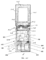
この折畳式携帯無線機は、図14に示すように、上ケース1301と下部筐体に該当する下ケース1302とがヒンジ部1303で連結された構造となっており、ヒンジ部1303を中心として回動することにより開いた状態と閉じた状態の2つの状態をとる。なお、上ケース1301と下ケース1302は絶縁体である樹脂の成型品により構成されている。
上ケース1301の表示素子1304が配置される面には、金属フレーム1305が装着されている。一般に、金属フレーム1305には、高い導電性を有し、かつ軽量で強度が高い金属、例えばマグネシウム合金が用いられる。これにより、薄型形状の上部筐体である上ケース1301の強度を確保するとともに金属フレーム1305がアンテナ素子としても動作する。一般に、金属フレーム1305の長辺の長さL1は90mm程度である。
金属フレーム1305と、ヒンジ金具1306が、取付ネジ1307によって上ケース1301に取り付けられることで、金属フレーム1305とヒンジ金具1306とが電気的に接続されるとともに、上ケース1301とヒンジ金具1306とが機械的に固定される。
As shown in FIG. 14, this foldable portable wireless device has a structure in which an
A
The
ヒンジ金具1306と、ヒンジ金具1308とが、連結手段に該当する回転軸1309により回動可能なように連結される。ヒンジ金具1306、ヒンジ金具1308及び回転軸1309は導電性の金属で形成されており、それぞれの間の接触点において電気的に導通するように構成される。これらのヒンジ金具1306、ヒンジ金具1308及び回転軸1309によってヒンジ部1303が構成されている。
ヒンジ金具1308の一部と、給電端子1310が取付ネジ1311によって下ケース1302に取り付けられることにより、ヒンジ金具1308と給電端子1310とが電気的に接続されるとともに、下ケース1302とヒンジ金具1308とが機械的に固定される。
The hinge fitting 1306 and the
A part of the
給電端子1310は、下ケース1302の内部に配置された回路基板1312上の整合回路1313を介して無線回路1314に接続される。回路基板1312は携帯無線機の各種機能を実現する回路部品が実装されたプリント基板であり、そのほぼ全面に回路の接地電位となるグランドパターンが形成されている。
このようにアンテナが構成された折畳式携帯無線機では、外部に配置されるヘリカルアンテナに比べ、アンテナ性能を改善できること、及び使用者の手との電磁的相互影響を改善できるため、使用者が手で保持して使用する状態においても高いアンテナ性能が得られる。
The
In a foldable portable wireless device with an antenna configured in this way, the antenna performance can be improved and the electromagnetic interaction with the user's hand can be improved compared to a helical antenna placed outside. High antenna performance can be obtained even when the hand is held and used.
しかしながら、上記アンテナの整合回路を使用者の手が近接した状態で最適化する構成では使用者の手が近接しない場合のアンテナ性能が劣化する点、及び、整合回路を最適化するだけでは改善量が小さいという点に課題がある。
また、上記折畳式携帯無線機に示されるような上下筐体の金属部分を利用する構成では使用者の手がアンテナ給電部に近接した場合に、アンテナ性能が若干劣化し、それに加え、閉じた状態におけるアンテナ性能が劣化するという課題がある。
However, in the configuration in which the antenna matching circuit is optimized in the state where the user's hand is in close proximity, the antenna performance is deteriorated when the user's hand is not in proximity, and the amount of improvement can be improved only by optimizing the matching circuit. There is a problem in that it is small.
In addition, in the configuration using the metal part of the upper and lower housings as shown in the above folding portable wireless device, when the user's hand is close to the antenna feeding unit, the antenna performance is slightly deteriorated, and in addition, the antenna is closed. There is a problem that the antenna performance deteriorates in the above state.
本発明は上記事情に鑑みてなされたものであり、その目的は、開いた通話状態及び閉じた状態の双方において高いアンテナ性能を確保できる折畳式携帯無線機を提供することにある。 The present invention has been made in view of the above circumstances, and an object thereof is to provide a foldable portable wireless device capable of ensuring high antenna performance both in an open call state and in a closed state.
上記目的を達成するために、本発明に係る折畳式携帯無線機は、第1の筐体に設けられる第1のアンテナ素子と、前記第1の筐体に対してヒンジ部によって回動可能に連結される第2の筐体と、前記第2の筐体内部の前記ヒンジ部に近い端部側に設けられるグランドパターンを有する回路基板と、前記第2の筐体内部の前記ヒンジ部に対して反対側の端部側に設けられた第2のアンテナ素子と、前記回路基板上の無線回路から前記第1のアンテナ素子に給電する第1給電手段と、前記回路基板上の無線回路から前記第2のアンテナ素子に給電する第2給電手段と、前記第1給電手段又は前記第2給電手段のいずれか一方を選択する切替手段とを備え、前記第1給電手段を選択した場合には、前記第1のアンテナ素子と前記回路基板上のグランドパターンとがダイポールアンテナとして動作し、前記第2給電手段を選択した場合には、前記第2のアンテナ素子と前記回路基板上のグランドパターンとがダイポールアンテナとして動作することを特徴とする。上記構成によれば、使用者の手が近接する通話状態においても高いアンテナ性能が得られる。 In order to achieve the above object, a foldable portable wireless device according to the present invention can be rotated by a first antenna element provided in a first housing and a hinge portion with respect to the first housing. A circuit board having a ground pattern provided on an end side close to the hinge portion inside the second housing, and the hinge portion inside the second housing. On the other hand, from a second antenna element provided on the opposite end side, a first power feeding means for feeding power to the first antenna element from the radio circuit on the circuit board, and a radio circuit on the circuit board When the second power feeding means for feeding power to the second antenna element and the switching means for selecting either the first power feeding means or the second power feeding means are selected, and the first power feeding means is selected. , The first antenna element and the gland on the circuit board And pattern operates as a dipole antenna, the second when the power supply means is selected, and the second antenna element and the ground pattern of the circuit board is characterized in that it operates as a dipole antenna. According to the above configuration, high antenna performance can be obtained even in a call state in which the user's hand is close.
また、前記回路基板上のグランドパターンは、前記第2の筐体内部の前記ヒンジ部側において前記第2の筐体の略半分の範囲に配置され、前記第2のアンテナ素子は、前記第2の筐体内部の前記ヒンジ部の反対側において前記第2の筐体の略半分の範囲に配置され、前記第2のアンテナ素子は、前記回路基板上のグランドパターンと所定の間隔を隔てて配置されかつ前記回路基板上の第2給電手段に電気的に接続されることを特徴とする。上記構成によれば、実際の無線機の構成において、使用者の手が近接する通話状態においても高いアンテナ性能が得られる。 In addition, the ground pattern on the circuit board is disposed in a range approximately half of the second casing on the hinge portion side inside the second casing, and the second antenna element is the second antenna element. The second antenna element is arranged at a predetermined distance from the ground pattern on the circuit board on the opposite side of the hinge portion inside the casing of the second casing. And electrically connected to the second power feeding means on the circuit board. According to the above configuration, high antenna performance can be obtained even in a call state in which the user's hand is close in the configuration of an actual radio device.
また、前記ヒンジ部は、導電性の金属で構成された第1ヒンジ部及び第2ヒンジ部と、前記第1ヒンジ部と前記第2ヒンジ部とを電気的に接続すると共に、回動可能に支持する連結部とを有し、前記第1ヒンジ部は、前記第1の筐体に設けられ、前記第1のアンテナ素子の端部に電気的に接続され、前記第2ヒンジ部は、前記第2の筐体に設けられ、前記回路基板上のグランドパターンと所定の間隔を隔てて配置されかつ前記回路基板上の第1給電手段に電気的に接続され、前記第1給電手段を選択した場合には、前記第1のアンテナ素子及び前記ヒンジ部と、前記回路基板上のグランドパターンとがダイポールアンテナとして動作することを特徴とする。上記構成によれば、回動可能なヒンジ部を適用することで、特別な部品を用いることなく低コストで且つ安定した給電構造を実現できるという効果が得られる。 In addition, the hinge part electrically connects the first hinge part and the second hinge part made of a conductive metal, and the first hinge part and the second hinge part, and is rotatable. The first hinge part is provided in the first housing and is electrically connected to an end of the first antenna element, and the second hinge part is Provided in the second casing, arranged at a predetermined interval from the ground pattern on the circuit board, and electrically connected to the first power feeding means on the circuit board, and the first power feeding means is selected In this case, the first antenna element, the hinge part, and the ground pattern on the circuit board operate as a dipole antenna. According to the said structure, the effect that a stable electric power feeding structure can be implement | achieved at low cost, without using special components by applying the hinge part which can be rotated is acquired.
また、前記第2のアンテナ素子を前記回路基板上の銅箔パターンで構成することを特徴とする。上記構成によれば、回路基板上の銅箔パターンをアンテナ素子として適用することで、部品点数削減及び組み立て工数削減によるコストダウンを実現できるという効果が得られる。 Further, the second antenna element is constituted by a copper foil pattern on the circuit board. According to the above configuration, by applying the copper foil pattern on the circuit board as an antenna element, it is possible to achieve an effect of realizing cost reduction by reducing the number of parts and the number of assembly steps.
また、前記第2の筐体内部において、前記回路基板側に配置される電子回路と前記第2のアンテナ素子側に配置される電子回路とを接続する回路にインダクタンス素子を挿入し、前記インダクタンス素子を前記回路基板上のグランドパターンと前記第2のアンテナ素子との間隔に配置することを特徴とする。上記構成によれば、第1のアンテナ素子の性能を維持した上で、第2のアンテナ素子の性能を向上できるという効果が得られる。 In addition, an inductance element is inserted into a circuit connecting the electronic circuit disposed on the circuit board side and the electronic circuit disposed on the second antenna element side inside the second casing, and the inductance element Is arranged at a distance between the ground pattern on the circuit board and the second antenna element. According to the above configuration, the performance of the second antenna element can be improved while maintaining the performance of the first antenna element.
また、前記第1の筐体と前記第2の筐体の開閉状態を検出する開閉検出手段を備え、前記開閉検出手段の検出結果に応じて前記切替手段を制御し、前記第1の筐体と前記第2の筐体が開かれている場合には前記第1の給電手段を選択し、前記第1の筐体と前記第2の筐体が閉じられている場合には前記第2の給電手段を選択することを特徴とする。上記構成によれば、前記第1の筐体と前記第2の筐体が閉じられている状態においても高いアンテナ性能が得られる。 In addition, an opening / closing detection means for detecting an open / closed state of the first casing and the second casing is provided, the switching means is controlled according to a detection result of the opening / closing detection means, and the first casing And when the second casing is open, the first power supply means is selected, and when the first casing and the second casing are closed, the second power supply is selected. The power supply means is selected. According to the above configuration, high antenna performance can be obtained even when the first casing and the second casing are closed.
また、前記第1の筐体と前記第2の筐体が開かれている場合において、携帯無線機を保持する手と前記第2の筐体との位置関係を検出する保持位置検出手段を備え、前記保持位置検出手段の検出結果に応じて前記切替手段を制御し、前記第2のアンテナ素子側を手で保持されている場合には前記第1の給電手段を選択し、前記ヒンジ部側を手で保持されている場合には前記第2の給電手段を選択することを特徴とする。上記構成によれば、保持位置が変化した状態においても常に高いアンテナ性能が得られる。 In addition, when the first casing and the second casing are opened, a holding position detecting unit that detects a positional relationship between the hand holding the portable wireless device and the second casing is provided. The switching unit is controlled according to the detection result of the holding position detecting unit, and when the second antenna element side is held by hand, the first feeding unit is selected and the hinge unit side is selected. The second power supply means is selected when the hand is held by hand. According to the above configuration, high antenna performance is always obtained even when the holding position is changed.
また、前記第1の筐体と前記第2の筐体の開閉状態を検出する開閉検出手段を備え、前記開閉検出手段の検出結果に応じて前記切替手段を制御し、前記第1の筐体と前記第2の筐体が閉じられている場合には前記第1の給電手段か前記第2の給電手段のいずれか一方を強制的に選択することを特徴とする。上記構成によれば、前記第1の筐体と前記第2の筐体が開かれている場合に選択されているアンテナによらず、閉じられている場合の最適なアンテナを選択することができ、閉じられた状態において、常に高いアンテナ性能が得られる。 In addition, an opening / closing detection means for detecting an open / closed state of the first casing and the second casing is provided, the switching means is controlled according to a detection result of the opening / closing detection means, and the first casing When the second casing is closed, either the first power feeding means or the second power feeding means is forcibly selected. According to the above configuration, it is possible to select an optimal antenna when the first casing and the second casing are closed, regardless of the antenna selected when the first casing and the second casing are opened. In the closed state, high antenna performance is always obtained.
また、前記保持位置検出手段として、光学センサ、温度センサもしくは静電センサのいずれか一つを備えたことを特徴とする。上記構成によれば、常に携帯無線機を保持する手と前記第2の筐体との位置関係を検出することができ、保持位置が変化した状態においても常に高いアンテナ性能が得られる。 In addition, the holding position detecting means includes any one of an optical sensor, a temperature sensor, and an electrostatic sensor. According to the above configuration, the positional relationship between the hand holding the portable wireless device and the second housing can be detected at all times, and high antenna performance is always obtained even when the holding position is changed.
また、前記切替手段を制御する方法として、前記無線回路の通信品質を比較し、前記通信品質が常に高くなる方の給電手段を選択する。上記構成によれば、常に高い通話品質を得られる。 Further, as a method for controlling the switching means, the communication quality of the radio circuit is compared, and the power feeding means whose communication quality is always higher is selected. According to the above configuration, high call quality can always be obtained.
また、前記無線回路の受信電界強度を比較し、前記受信電界強度が常に高くなる方の給電手段を選択することを特徴とする。上記構成によれば、実際の使用環境に応じて、アンテナを選択し、常に高いアンテナ性能を得られる。 Further, the received electric field strength of the radio circuit is compared, and a power feeding unit that always increases the received electric field strength is selected. According to the above configuration, an antenna can be selected according to the actual use environment, and high antenna performance can always be obtained.
また、前記第1給電手段と前記第2給電手段とに電力を分配して給電する手段を備えることを特徴とする。上記構成によれば、切替手段を用いることなく、常に高いアンテナ性能を得られる。 The power supply device may further include a power supply unit that distributes power to the first power supply unit and the second power supply unit. According to the above configuration, high antenna performance can always be obtained without using switching means.
以上説明したように、本発明の折畳式携帯無線機によれば、第1の筐体と前記第2の筐体を開いた通話状態及び第1の筐体と前記第2の筐体を閉じた状態において高いアンテナ性能を確保できる。 As described above, according to the foldable portable wireless device of the present invention, the first casing and the second casing are in a talking state, and the first casing and the second casing are connected. High antenna performance can be secured in the closed state.
以下、本発明に係る折畳式携帯無線機の実施形態ついて、図面を参照して詳細に説明する。
なお、背景技術にて説明した折畳式携帯無線機の符号と同一の符号を付すものは同一の構成要素を示しており、その詳細な説明を省略する。
また、本実施形態では、無線周波数を1950MHzに設定した場合を例として説明する。
DESCRIPTION OF EMBODIMENTS Hereinafter, embodiments of a foldable portable wireless device according to the present invention will be described in detail with reference to the drawings.
In addition, what attaches | subjects the code | symbol same as the code | symbol of the folding portable radio apparatus demonstrated by background art has shown the same component, The detailed description is abbreviate | omitted.
In the present embodiment, a case where the radio frequency is set to 1950 MHz will be described as an example.
(第1実施形態)
本発明に係る折畳式携帯無線機の第1実施形態について図1〜図7を用いて詳細に説明する。
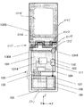
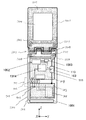
図1は本発明に係る第1実施形態の折畳式携帯無線機の基本的構成を示す正面図である。
図1に示すように、第1実施形態に係る折畳式携帯無線機は、下ケース1302に、第1の回路基板101、第2の回路基板102、アンテナ切替え部103、データ処理部104、第1、第2の回路基板間を接続する接続部105、外部メモリドライブ107を備えている。
(First embodiment)
A foldable portable wireless device according to a first embodiment of the present invention will be described in detail with reference to FIGS.
FIG. 1 is a front view showing a basic configuration of a folding portable wireless device according to a first embodiment of the present invention.
As shown in FIG. 1, the foldable portable wireless device according to the first embodiment includes a
第1の回路基板101は折畳式携帯無線機の各種機能を実現する回路部品が実装された例えば厚さ1mmのプリント基板であり、そのほぼ全面に回路の接地電位となるグランドパターンが形成されている。その寸法は縦40mm、横40mmで設定される。
第2の回路基板102は折畳式携帯無線機の各種機能及び外部メモリドライブ107の部品が実装された厚さ1mmのプリント基板であり、第1の回路基板101と同様にほぼ全面に回路の接地電位となるグランドパターンが形成されている。寸法は縦30mm、横40mmで設定される。
The
The
また、第2の回路基板102上には、折畳式携帯無線機の駆動用電源である外部電源108が配置される。外部電源108の寸法は縦25mm、横35mmで設定され、第2の回路基板102と2mmの間隔で配置される。また、内部に電極金属部109を備える。
第2の回路基板102のグランドパターンは第1の回路基板101を接地導体とするアンテナ素子としても動作する。
第1の回路基板101と第2の回路基板102は接続部105を介して接続される。第1の回路基板101と第2の回路基板間102の間隔は例えば20dB以上のアイソレーションを確保するために、2mm以上で設定される。
On the
The ground pattern of the
The
接続部105は第1の回路基板101と第2の回路基板102を接続する複数の接続線から構成され、これら接続線は、例えば、外部メモリドライブ107とデータ処理部104間を接続する制御線とデータ線、外部電源108と無線回路1314を接続する電源線とグランド線等である。
各接続線が第1の回路基板101と第2の回路基板102間を接続することにより、第1の回路基板101と第2の回路基板102間のアイソレーションが大幅に劣化する。そこで、各接続線にはインダクタンス素子106が配置される。インダクタンス素子106を配置することで、データ信号や制御系の直流信号を通過させつつ、無線周波数1950MHzにおける高周波信号を遮断する。
The
By connecting each connection line between the
これにより、無線周波数1950MHzにおいて、第1の回路基板101と第2の回路基板102との間が接続部105によって接続された状態においても、無線周波数1950MHzにおいて、第1の回路基板101と第2の回路基板102間の高アイソレーションを確保できる。
Thus, even when the
設定されるインダクタンス値は接続線の本数及び無線周波数により異なる。例えば、データ転送用の信号線、制御線、グランド線2本で合計5本の場合には、インダクタンス素子106は470nHが設定される。インダクタンスは並列に配置されることで、1/nの値となるため、接続本数が増加する場合はより値の大きいインダクタンスを設定する。
インダクタンス素子106は出来る限り小型であることが望ましいことから、例えば1.0mm×0.5mm×0.5mmのチップ素子を用いる。
The set inductance value varies depending on the number of connection lines and the radio frequency. For example, in the case of a total of five data transfer signal lines, control lines, and two ground lines, the
Since the
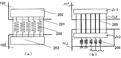
図2はチップ素子以外で接続部105のインダクタンスを構成した場合を示す。図2( a )、( b )は第1の回路基板101と第2の回路基板102をフレキシブルケーブルで接続する構成である。
図2( a )において、フレキシブルケーブル201は、第1のコネクタ202を介して第1の回路基板101に接続され、また、第2のコネクタ203を介して第2の回路基板102に接続される。第1の接続線204は幅0.35mmの銅箔で構成され、第1の接続線204の中央部においてメアンダ形状で構成することでインダクタンス値を設定する。
FIG. 2 shows a case where the inductance of the connecting
In FIG. 2A, the
また、図2(b)は、図2(a)において、第1の接続線204の中央部で構成したインダクタンスを第2の回路基板102上で構成したものである。第2の接続線205は幅0.5mmの銅箔で構成され、第2のコネクタ203を介して第2の回路基板102に接続される。第2の回路基板102上で構成された第3の接続線206は、第2の回路基板102の銅箔パターンによりインダクタンス値を設定する。
第2の回路基板102上で第3の接続線206が配置される箇所近傍では、第3の接続線206以外の銅箔パターンは削除される。このような構成とすることで、インダクタンス素子106と同等の効果を得ることができる。
Further, FIG. 2B shows an inductance formed on the
In the vicinity of the place where the
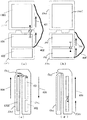
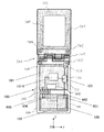
図3は本発明に係る第1実施形態の折畳式携帯無線機の閉じた状態における基本的構成を示す側面図、図4は本発明に係る第1実施形態の折畳式携帯無線機の開いた状態及び閉じた状態を示す模式図である。なお、図4(a)は、開いた状態において、第1のアンテナを選択した状態を示す図、図4(b)は、開いた状態において、第2のアンテナを選択した状態を示す図、図4(c)は、閉じた状態において、第1のアンテナを選択した状態を示す図、図4(d)は、閉じた状態において、第2のアンテナを選択した状態を示す図である。 FIG. 3 is a side view showing a basic configuration in a closed state of the foldable portable radio apparatus according to the first embodiment of the present invention, and FIG. 4 is a diagram of the foldable portable radio apparatus according to the first embodiment of the present invention. It is a schematic diagram which shows the open state and the closed state. 4A shows a state in which the first antenna is selected in the open state, and FIG. 4B shows a state in which the second antenna is selected in the open state. FIG. 4C is a diagram illustrating a state in which the first antenna is selected in the closed state, and FIG. 4D is a diagram illustrating a state in which the second antenna is selected in the closed state.
ここで、第1の回路基板101と金属フレーム1305で構成されるアンテナを第1のアンテナ、第1の回路基板101と第2の回路基板102で構成されるアンテナを第2のアンテナと設定する。
図4(a)は開いた状態における第1のアンテナを選択した場合を示している。第1のアンテナは第1の回路基板101と金属フレーム1305間をダイポール動作させる構成である。一方、図4(b)は開いた状態における第2のアンテナを選択した場合を示している。第2のアンテナは第1の回路基板101と第2の回路基板102間をダイポール動作させる構成である。
Here, an antenna constituted by the
FIG. 4A shows a case where the first antenna is selected in the open state. The first antenna is configured to perform a dipole operation between the
図4(a)における第1の矢印401は第1のアンテナにおける電流の向きを示している。また、第1の分布402は第1のアンテナにおける電流強度分布を示している。第1のアンテナは第1の回路基板101と金属フレーム1305間でダイポール動作しているため、第1の回路基板101と金属フレーム1305に分布する電流の向きは同一となる。また、給電部が電流強度最大となる強度分布となる。第1の回路基板101と金属フレーム1305で電流強度の分布が異なるのは金属フレーム1305の長さが無線周波数1950MHzのλ/4(約38cm)に対して長いためである。また、第1のアンテナを選択している場合、電流は第2の回路基板102上には分布しない。
A
一方、図4(b)における第2の分布403は第2のアンテナにおける電流強度分布を示している。第2のアンテナは第1の回路基板101と第2の回路基板102間でダイポール動作している。第1のアンテナと同様に第1の回路基板101と第2の回路基板102に分布する電流の向きは同一である。給電部が電流強度最大となる強度分布となるが、第1のアンテナとは異なり、電流は第1の回路基板101、第2の回路基板102上に分布し、金属フレーム1305上には分布しない。図4(a),(b)から第1のアンテナ、第2のアンテナ間の相違点は給電部の位置及び電流分布である。
On the other hand, the second distribution 403 in FIG. 4B shows the current intensity distribution in the second antenna. The second antenna performs a dipole operation between the
ここで、一般に使用者の手がアンテナに近接する場合、給電部周辺がもっともアンテナ性能に及ぼす影響が大きいことが知られている。そのため、折畳式携帯無線機において、使用者の手の位置により、給電部を使用者の手近傍から移動できれば、どのような保持状況においても常に安定したアンテナ性能を確保できる。 Here, it is generally known that when the user's hand is close to the antenna, the periphery of the power feeding unit has the greatest influence on the antenna performance. Therefore, in a foldable portable wireless device, stable antenna performance can be ensured in any holding state as long as the power feeding unit can be moved from the vicinity of the user's hand depending on the position of the user's hand.
図4(c)は第1のアンテナを選択した状態で折畳式携帯無線機を閉じた状態を示している。図4(a)では電流の向きを示す第1の矢印401は、第1の回路基板101、金属フレーム1305上で同一であったが、図4(c)では給電部で折畳まれるため、金属フレーム1305上の電流の向きを示す第2の矢印404と第1の回路基板101上の電流の向きを示す第3の矢印405は反対となり、電流分布は打ち消される。
FIG. 4C shows a state in which the foldable portable wireless device is closed with the first antenna selected. In FIG. 4A, the
一方、図4(d)は電流が金属フレーム1305上に分布しない構成であるため、第2のアンテナを選択した状態で第1の回路基板101と第2の回路基板102上の電流の向きを示す第4の矢印406は同一となる。この場合、図4(d)は、図4(c)に比べ無線周波数1950MHzにおいて高いアンテナ性能が得られる。この場合X−Z面PAG(pattern average gain)はそれぞれ−20dBd、−10dBdとなり図4(d)の方が図4(c)に比べ約10dB高い。PAGは一平面(ここではX−Z面)の電力指向性を平均化したものである。通常、半波長ダイポールアンテナのそれを0dBdと規定し、アンテナの評価指標として用いている。
On the other hand, since FIG. 4D shows a configuration in which the current is not distributed on the
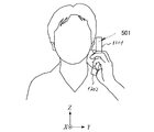
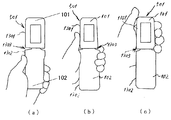
図5は使用者が折畳式携帯無線機501を手で保持して通話を行っている状態(以下、通話状態)を示し、図6(a)〜(c)は、上記の通話状態において、折畳式携帯無線機501を手で保持する場合の手の位置の違いを模式的に示した図である。ここで、使用者に対して、天頂方向をZ、正面方向をXと座標系を設定する。なお、図6(a)は折畳式携帯無線機501の下部筐体である下ケース1302の下寄りを保持した場合(下部保持状態)を示し、図6(b)は折畳式携帯無線機501の中央部にあるヒンジ部1303近傍を保持した場合(中央保持状態)を示し、図6(c)は折畳式携帯無線機501の上部筐体である上ケース1301を保持した場合(上部保持状態)を示している。
FIG. 5 shows a state in which the user is holding the foldable
図7に、第1実施形態に係る折畳式携帯無線機を保持する手の位置を変化させた場合の第1のアンテナ、第2のアンテナの通話時アンテナ利得を示す。
図において破線701にて示すグラフは第1のアンテナ、二点鎖点702にて示すグラフは第2のアンテナにおけるX−Y面PAG利得変化をあらわしている。
FIG. 7 shows antenna gains during a call of the first antenna and the second antenna when the position of the hand holding the folding portable wireless device according to the first embodiment is changed.
In the figure, a graph indicated by a
そして、直線703にて示すグラフは第1実施形態の折畳式携帯無線機において保持する手の位置によって第1のアンテナ、第2のアンテナを切替えた場合のアンテナ利得変化である。比較するために、一点鎖線704にて示すグラフは、従来のアンテナにおける利得変化を表している。測定周波数は1950MHzである。
A graph indicated by a
このように、第1のアンテナ、第2のアンテナ、従来のアンテナの下部保持状態(a)におけるアンテナ利得はそれぞれ−8dBd、−12dBd、−9dBdとなり、第1のアンテナの方が第2のアンテナより4dB、従来のアンテナより1dB高い。
一方、中央保持状態(b)におけるアンテナ利得はそれぞれ−11dBd、−8dBd、−10dBdとなり、第2のアンテナの方が第1のアンテナより3dB高く、従来のアンテナより2dB高い。
また、上部保持状態(c)におけるアンテナ利得はそれぞれ−8dBd、−7dBd、−8dBdとなり、第2のアンテナの方が第1のアンテナ、従来のアンテナより1dB高い。
Thus, the antenna gains in the lower holding state (a) of the first antenna, the second antenna, and the conventional antenna are −8 dBd, −12 dBd, and −9 dBd, respectively, and the first antenna is the second antenna. 4 dB higher than the conventional antenna.
On the other hand, the antenna gain in the center holding state (b) is -11 dBd, -8 dBd, and -10 dBd, respectively, and the second antenna is 3 dB higher than the first antenna and 2 dB higher than the conventional antenna.
The antenna gain in the upper holding state (c) is -8 dBd, -7 dBd, and -8 dBd, respectively, and the second antenna is 1 dB higher than the first antenna and the conventional antenna.
このことから、第1実施形態の折畳式携帯無線機におけるアンテナでは、下部保持状態(a)の場合はアンテナ1を選択し、中央保持状態(b)、下部保持状態(c)の場合はアンテナ2を選択することで、従来のアンテナに比べ、(a)、(b)、(c)それぞれの保持状態において、1dB、2dB、1dB高いアンテナ利得を得られる。 From this, in the antenna in the foldable portable wireless device of the first embodiment, the antenna 1 is selected in the lower holding state (a), and in the central holding state (b) and the lower holding state (c). By selecting the antenna 2, it is possible to obtain an antenna gain that is 1 dB, 2 dB, and 1 dB higher than the conventional antenna in each of the holding states (a), (b), and (c).
上記説明したように、第1実施形態に係る折畳式携帯無線機では、従来のアンテナのようにヒンジ部1303だけに給電機能を持たせている構造とは異なり、使用者の保持状態によって、アンテナの給電位置を移動させる構造を備えることで、使用者の手がアンテナの給電点に近接することによる使用者の手とアンテナ間の電磁的相互作用を低減し、どの保持状態においても高いアンテナ性能を確保することができる。
また、第1実施形態では、上ケース1301が金属フレームで構成されている例を挙げているが、例えば、上ケース1301が樹脂等の非導電素材であっても、上回路基板等のグランドパターンにヒンジ部1303を介して給電できる構成であれば、同等のアンテナ性能を確保することができる。
As described above, in the foldable portable wireless device according to the first embodiment, unlike the conventional antenna having a power feeding function only in the
In the first embodiment, the
加えて、第1の回路基板101は1枚基板構造を例として挙げたが、例えば小型化の為にX軸上に多層化された構造の回路基板においても、アンテナ素子の接地導体として動作する構成であれば、同等の効果が得られる。
In addition, the
(第2実施形態)
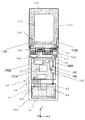
本発明に係る折畳式携帯無線機の第2実施形態を、図8を用いて詳細に説明する。図8は本発明に係る第2実施形態の折畳式携帯無線機の基本的構成を示す正面図である。
第2実施形態における折畳式携帯無線機は、折畳式携帯無線機の各機能を実現するための回路基板が、第1実施形態における第1の回路基板101とほぼ同等のサイズで実現された場合のアンテナ構成に関するものである。
図8に示すように、第2実施形態における折畳式携帯無線機は、下ケース1302に、第3の回路基板801、第4の回路基板802、アンテナ素子803、接続端子部804を備えている。
(Second Embodiment)
A second embodiment of the folding portable wireless device according to the present invention will be described in detail with reference to FIG. FIG. 8 is a front view showing a basic configuration of a folding portable wireless device according to the second embodiment of the present invention.
In the foldable portable radio device according to the second embodiment, a circuit board for realizing each function of the foldable portable radio device is realized with a size substantially equal to that of the
As shown in FIG. 8, the folding portable wireless device according to the second embodiment includes a
第3の回路基板801は、折畳式携帯無線機の各種機能を実現するための全回路部品が実装された厚さ1mmのプリント基板であり、そのほぼ全面に回路の接地電位となるグランドパターンが形成されている。その寸法は縦45mm、横40mmで設定される。
第4の回路基板802は、外部電源108、外部メモリドライブ107を保持するために配置され、回路の接地電位となるグランドパターンはほとんど形成されていない。その寸法は縦35mm、横40mmで設定される。
アンテナ素子803は、第4の回路基板802、外部電源108とX軸上に重なる位置に配置され、例えば厚さ約0.3mmの銅板で構成されている。その寸法は縦40mm、横30mmで設定される。
The
The
The
アンテナ素子803と外部電池108は、相互影響を低減するために2mm以上の間隔を設定することが望ましい。アンテナ素子803は、接続端子部804を用いて無線回路1314と接続する。接続端子部804はX軸方向に高さをもつ、金属性の接触ピンであり、表面にはアンテナ素子803との接触安定性を確保するために金メッキが施されている。
It is desirable to set an interval of 2 mm or more between the
上記の第2実施形態に係る折畳式携帯無線機によれば、折畳式携帯無線機の各機能を実現する回路基板の小型化が可能となった場合でも、新たにアンテナ素子となる板金を追加することで、第1実施形態と同様に、使用者の手が配置される位置により、使用するアンテナを選択することが可能となり、使用者の手がアンテナの給電点に近接することによる使用者の手とアンテナ間の電磁的相互作用を低減し、どの保持状態においても高いアンテナ性能を確保することができる。 According to the foldable portable wireless device according to the second embodiment, even when the circuit board that realizes each function of the foldable portable wireless device can be miniaturized, a sheet metal that becomes a new antenna element As in the first embodiment, the antenna to be used can be selected depending on the position where the user's hand is arranged, and the user's hand is close to the feeding point of the antenna. Electromagnetic interaction between the user's hand and the antenna can be reduced, and high antenna performance can be ensured in any holding state.
なお、第3の回路基板801は、本実施形態では1枚基板構造を例として挙げたが、例えば小型化の為にX軸上に多層化された構造の回路基板においても、アンテナ素子の接地導体として動作する構成であれば、同等の効果が得られる。
また、アンテナ素子803の形状は、所望の無線周波数において、共振する大きさであればどのような形状でもよく、板状だけでなく、線状又はメアンダ形状においても同等の効果が得られる。
Note that the
The shape of the
(第3実施形態)
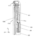
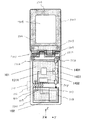
本発明に係る折畳式携帯無線機の第3実施形態を、図9を用いて詳細に説明する。図9は本発明に係る第3実施形態の折畳式携帯無線機の基本的構成を示す正面図である。
図9に示すように、第3実施形態では、第1実施形態における折畳式携帯無線機の下ケース1302内の構成において、電池内の電極金属部109をアンテナ素子として利用する構成としている。
給電端子901は、電池内の電極金属部109と電気的に接続され、電池部のグランド端子903及び電池部の電源ライン端子904に対して、折畳式携帯無線機の幅方向に対して対称の位置に設置される。
(Third embodiment)
A third embodiment of the folding portable wireless device according to the present invention will be described in detail with reference to FIG. FIG. 9 is a front view showing a basic configuration of a folding portable wireless device according to the third embodiment of the present invention.
As shown in FIG. 9, in 3rd Embodiment, it is set as the structure which utilizes the
The
給電端子901は、接続ピン902を介して無線回路1314に接続される。給電端子901は、接続用の金属金具であり、接続ピン902と接触圧により接続される。給電端子901、接続ピン902の表面には、接触の安定性及び腐食耐性を確保するために、金メッキが施される。また、例えば携帯機器では外部電源としてリチウムイオンが使用される。これにより、第1の回路基板101と電池内の電極金属部109間でアンテナを構成することが可能となる。
The
上記の第3実施形態に係る折畳式携帯無線機によれば、折畳式携帯無線機の下ケース1302側下部位置に配置される電池内の電極金属部109をアンテナ素子として利用することで、第1実施形態と同様に、使用者の手が配置される位置により、使用するアンテナを選択することが可能となり、使用者の手がアンテナの給電点に近接すことによる使用者の手とアンテナ間の電磁的相互作用を低減し、どの保持状態においても高いアンテナ性能を確保することができる。
According to the folding portable wireless device according to the third embodiment, the
なお、第1の回路基板101は、本実施形態では、1枚基板構造を例として挙げたが、例えば小型化のためにX軸上に多層化された構造の回路基板においても、アンテナ素子の接地導体として動作する構成であれば、同等の効果が得られる。
さらに、外部電源の例として、リチウムイオンを挙げたが、材料を金属体で覆う構成であるなら、どのような材料を用いた外部電源であっても同等の効果が得られる。
In the present embodiment, the
Furthermore, although lithium ions are given as an example of the external power source, the same effect can be obtained regardless of the external power source using any material as long as the material is covered with a metal body.
(第4実施形態)
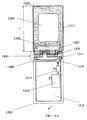
本発明に係る第4実施形態の折畳式携帯無線機について、図10を用いて詳細に説明する。
図10に示すように、第4実施形態の折畳式携帯無線機では、使用者の手を検知するセンサ素子1001、制御部1002、折畳式携帯無線機の開閉状態を検知する検知素子1003を備えている。
第1のアンテナは主に本実施形態において、使用者の手がセンサ素子1001において、検知された状態で使用される。一方、第2のアンテナは使用者の手がセンサ素子1001において、検知されない状態で使用される。
(Fourth embodiment)
A foldable portable wireless device according to a fourth embodiment of the present invention will be described in detail with reference to FIG.
As shown in FIG. 10, in the foldable portable wireless device of the fourth embodiment, a
In the present embodiment, the first antenna is mainly used in a state where the user's hand is detected by the
センサ素子1001は樹脂と金属電極から構成されている柔軟性のある圧力センサである。センサ素子のサイズは厚さ0.5mmであり、下ケース1302下端部の樹脂に貼り付けて使用する。
図6(a)に示したような下部保持状態においては、使用者の手がセンサ素子1001に接触する。この場合は、センサ素子1001は使用者の手が近接しているという検出信号を制御部1002に出力する。制御部1002はセンサ素子1001からの検出信号に基づいて、アンテナ切替え部103を制御する。この場合は、アンテナ切替え部103は無線回路1314と第1の端子110を接続し、第1のアンテナを構成する。
The
In the lower holding state as shown in FIG. 6A, the user's hand contacts the
一方、図6(b)、(c)に示したような中央保持状態、上部保持状態においては、使用者の手がセンサ素子1001に接触しない。そのため、センサ素子1001は検知信号を出力しない。この場合、アンテナ切替え部103は無線回路1314と第2の端子111を接続し、第2のアンテナを構成する。
また、検知素子1003は磁束の変化を感知するホール・センサであり、金属が近接したことを検出する近接センサの一つである。本実施形態おける折畳式携帯無線機が閉じた状態の場合、検知素子1003は金属フレーム1305が近接することを検知し、検出信号を制御部1002に出力する。制御部1002は折畳式携帯無線機が閉じた状態では検知素子1003の出力結果によらず、アンテナ切替え部103は無線回路1314と端子111を接続する。これにより、本実施例における折畳式携帯無線機が閉じた状態の場合、第2のアンテナが選択される。
On the other hand, in the center holding state and the upper holding state as shown in FIGS. 6B and 6C, the user's hand does not contact the
The
上記の第4実施形態に係る折畳式携帯無線機によれば、従来のアンテナのようにヒンジ部1303だけに給電機能を持たせている構造とは異なり、使用者の保持状態によって、アンテナの給電位置を移動させる構造を備えることで、使用者の手がアンテナの給電点に近接することによる使用者の手とアンテナ間の電磁的相互作用を低減し、どの保持状態においても高いアンテナ性能を確保することができる。また、検知素子1003からなる開閉検知手段を併用することにより、開いた状態において一方のアンテナを選択した状態で折畳式携帯無線機が閉じられた場合においても、最適なアンテナを選択することが可能となり、高いアンテナ性能を確保することができる。
According to the foldable portable wireless device according to the fourth embodiment, unlike the conventional antenna in which only the
なお、本実施形態では使用者の手を検知するセンサ素子1001として、圧力センサを例に挙げているが、例えば、静電気センサ、赤外線センナ、温度センサ、湿度センサのように使用者の手が近接したことによる変化を検知できる素子構成であれば同等のアンテナ性能を確保することができる。
また、本実施形態ではセンサ素子1001を下ケース1302の下端部に配置しているが、使用者の手が近接したことによる変化を検知できる位置であれば、例えば図11に示すように、第2のセンサ素子1101、第3のセンサ素子1102として、上ケース1301のヒンジ部1303近傍における側部位置に配置されていても同等のアンテナ性能を確保することができる。
In the present embodiment, a pressure sensor is taken as an example of the
In the present embodiment, the
加えて、上ケース1301が金属フレームで構成されている例を挙げているが、例えば、上ケース1301が樹脂等の非導電素材であっても、上回路基板等のグランドパターンにヒンジ部1303を介して給電できる構成であれば、同等のアンテナ性能を確保することができる。
In addition, an example is given in which the
(第5実施形態)
本発明に係る第5実施形態の折畳式携帯無線機について、図12を用いて詳細に説明する。
図12に示すように、第5実施形態の折畳式携帯無線機は、受信電界強度を検知する受信レベル検知部1201、受信レベル検知部内のメモリ部1203、比較部1202を備えている。
(Fifth embodiment)
A foldable portable wireless device according to a fifth embodiment of the present invention will be described in detail with reference to FIG.
As shown in FIG. 12, the foldable portable wireless device of the fifth embodiment includes a reception
そして、この折畳式携帯無線機では、例えば、無線回路1314が第1の端子110に接続された状態(第1のアンテナを選択時)において、受信電界レベルを受信レベル検知部内のメモリ部1203に一端記憶する。その後、無線回路1314を端子111に切替えた状態(第2のアンテナを選択時)と設定し、第2のアンテナを選択した場合の受信電界レベルと、メモリ部1203の受信電界レベルを、比較部1202を用いて比較する。この比較部1202の検出結果に基づいて受信レベル検知部1201は常に受信電界レベルの高いアンテナを選択するようにアンテナ切替え部103を制御する。
In this foldable portable wireless device, for example, in a state where the
上記の第5実施形態に係る折畳式携帯無線機によれば、使用者の手の近接を検知する検知素子を用いることなく、使用者の保持状態によって、アンテナの給電位置を移動させる構造を備えることで、使用者の手がアンテナの給電点に近接することによる使用者の手とアンテナ間の電磁的相互作用を低減し、どの保持状態においても高いアンテナ性能を確保することができる。 According to the foldable portable wireless device according to the fifth embodiment, the structure in which the feeding position of the antenna is moved according to the holding state of the user without using the detection element that detects the proximity of the user's hand. By providing, the electromagnetic interaction between the user's hand and the antenna due to the proximity of the user's hand to the feeding point of the antenna can be reduced, and high antenna performance can be ensured in any holding state.
また、使用者の保持状態だけでなく、使用環境に対しても常に最適なアンテナを設定することが可能であり、常に安定したアンテナ性能を確保できる。
なお、本実施形態では、アンテナを切替える比較指標として、受信電界レベルを用いているが、第1のアンテナ、第2のアンテナの選択時の無線性能を評価できる指標であれば、BER(Bit error rate)を用いても同等のアンテナ性能を確保することができる。
In addition, it is possible to always set an optimal antenna not only for the user's holding state but also for the usage environment, and it is possible to always ensure stable antenna performance.
In this embodiment, the received electric field level is used as a comparison index for switching antennas. However, if the index is an index that can evaluate the wireless performance when the first antenna and the second antenna are selected, BER (Bit error rate) can be used to ensure the same antenna performance.
(第6実施形態)
本発明に係る第6実施形態の折畳式携帯無線機について、図13を用いて詳細に説明する。
図13に示すように、第6実施形態に係る折畳式携帯無線機は、第1のアンテナ、第2のアンテナへ電力分配回路を用いて同時に給電する。
第1のアンテナ、第2のアンテナは、それぞれ高周波同軸ケーブル1401、1402を介して電力分配合成器1403及び無線回路1314に接続される。電力分配合成器1403は、例えばウィルキンソン型パワーデバイダで構成される。
(Sixth embodiment)
A foldable portable wireless device according to a sixth embodiment of the present invention will be described in detail with reference to FIG.
As shown in FIG. 13, the foldable portable wireless device according to the sixth embodiment supplies power simultaneously to the first antenna and the second antenna using a power distribution circuit.
The first antenna and the second antenna are connected to the
ここで、本実施形態におけるアンテナの下部保持状態(図6(a)参照)におけるアンテナ利得は、−8.5dBdとなる。一方、中央保持状態(図6(b)参照)におけるアンテナ利得は−9dBdとなり、上部保持状態(図6(c参照)におけるアンテナ利得は−8dBdとなる。これは、アンテナ切替え手段を用いた場合の利得、−8dBd、−7dBd、−7dBdより若干低い利得であるが、ほぼそれに近いアンテナ性能を実現できる。
また、従来のアンテナと比較すると、下部保持状態、中央保持状態及び上部保持状態の各保持状態(図6( a )、(b)、(c)参照)のそれぞれにおいて0.5dBから1.0dBアンテナ性能を改善できる。
Here, the antenna gain in the lower holding state (see FIG. 6A) of the antenna in the present embodiment is −8.5 dBd. On the other hand, the antenna gain in the center holding state (see FIG. 6B) is −9 dBd, and the antenna gain in the upper holding state (see FIG. 6C) is −8 dBd. The gain is slightly lower than -8 dBd, -7 dBd, and -7 dBd, but antenna performance close to that can be realized.
Further, compared with the conventional antenna, 0.5 dB to 1.0 dB in each of the holding states of the lower holding state, the center holding state, and the upper holding state (see FIGS. 6A, 6B, and 6C). Antenna performance can be improved.
上記の第6実施形態に係る折畳式携帯無線機によれば、第1のアンテナ及び第2のアンテナの両方に分配給電することで、アンテナの切替え動作を行わない場合でも使用者の手によって保持状態が変化しても高いアンテナ利得を確保できる。
なお、電力分配合成器はウィルキンソン型パワーデバイダに限るものではなく、双方向性を有する電力分配器であれば同等の効果を有する。
また、給電系に用いる給電線路は高周波同軸ケーブルに限るものではなく、マイクロストリップラインなどの回路基板上に形成された伝送線路であってもよい。
According to the foldable portable wireless device according to the sixth embodiment described above, by distributing power to both the first antenna and the second antenna, even when the antenna switching operation is not performed, the user's hand Even if the holding state changes, a high antenna gain can be secured.
The power divider / combiner is not limited to the Wilkinson power divider, and has the same effect as long as it is a bidirectional power divider.
Further, the feed line used in the feed system is not limited to the high-frequency coaxial cable, and may be a transmission line formed on a circuit board such as a microstrip line.
折畳式携帯無線機の通話状態において、高いアンテナ性能を確保することに有用である。 This is useful for ensuring high antenna performance in a call state of a foldable portable wireless device.
101 第1の回路基板
102 第2の回路基板
103 アンテナ切替え部
106 インダクタンス素子
108 外部電源
109 電極金属部
201 フレキシブルケーブル
204 第1の接続線
205 第2の接続線
206 第3の接続部
501 折畳式携帯無線機
801 第3の回路基板
802 第4の回路基板
803 アンテナ素子
903 グランド端子
904 電源ライン端子
1001 センサ素子
1002 制御部
1003 検知素子
1101 第2の検知素子
1102 第3の検知素子
1202 比較部
1201 受信レベル検知部
1203 メモリ部
1301 上ケース
1302 下ケース
1303 ヒンジ部
1304 表示素子
1305 金属フレーム
1310 給電端子
1312 回路基板
1313 整合回路
1314 無線回路
1401 第1の高周波同軸ケーブル
1402 第2の高周波同軸ケーブル
1403 電力分配合成器
DESCRIPTION OF
109
205
Claims (12)
前記第1の筐体に対してヒンジ部によって回動可能に連結される第2の筐体と、
前記第2の筐体内部の前記ヒンジ部に近い端部側に設けられるグランドパターンを有する回路基板と、
前記第2の筐体内部の前記ヒンジ部に対して反対側の端部側に設けられた第2のアンテナ素子と、
前記回路基板上の無線回路から前記第1のアンテナ素子に給電する第1給電手段と、
前記回路基板上の無線回路から前記第2のアンテナ素子に給電する第2給電手段と、
前記第1給電手段又は前記第2給電手段のいずれか一方を選択する切替手段とを備え、
前記第1給電手段を選択した場合には、前記第1のアンテナ素子と前記回路基板上のグランドパターンとがダイポールアンテナとして動作し、
前記第2給電手段を選択した場合には、前記第2のアンテナ素子と前記回路基板上のグランドパターンとがダイポールアンテナとして動作することを特徴とする折畳式携帯無線機。 A first antenna element provided in the first housing;
A second casing rotatably connected to the first casing by a hinge portion;
A circuit board having a ground pattern provided on an end side close to the hinge portion inside the second housing;
A second antenna element provided on an end side opposite to the hinge portion inside the second casing;
First feeding means for feeding power to the first antenna element from a radio circuit on the circuit board;
Second power feeding means for feeding power to the second antenna element from a radio circuit on the circuit board;
Switching means for selecting either the first power supply means or the second power supply means,
When the first feeding unit is selected, the first antenna element and the ground pattern on the circuit board operate as a dipole antenna,
When the second power feeding unit is selected, the folding portable wireless device, wherein the second antenna element and the ground pattern on the circuit board operate as a dipole antenna.
前記第2のアンテナ素子は、前記第2の筐体内部の前記ヒンジ部の反対側において前記第2の筐体の略半分の範囲に配置され、
前記第2のアンテナ素子は、前記回路基板上のグランドパターンと所定の間隔を隔てて配置されかつ前記回路基板上の前記第2給電手段に電気的に接続されることを特徴とする請求項1記載の折畳式携帯無線機。 The ground pattern on the circuit board is disposed in a substantially half range of the second casing on the hinge part side inside the second casing,
The second antenna element is disposed in a substantially half range of the second casing on the opposite side of the hinge portion inside the second casing,
2. The second antenna element is disposed at a predetermined distance from a ground pattern on the circuit board and is electrically connected to the second power feeding unit on the circuit board. The foldable portable wireless device described.
前記第1ヒンジ部は、前記第1の筐体に設けられ、前記第1のアンテナ素子の端部に電気的に接続され、
前記第2ヒンジ部は、前記第2の筐体に設けられ、前記回路基板上のグランドパターンと所定の間隔を隔てて配置されかつ前記回路基板上の第1給電手段に電気的に接続され、
前記第1給電手段を選択した場合には、前記第1のアンテナ素子及び前記ヒンジ部と、前記回路基板上のグランドパターンとがダイポールアンテナとして動作することを特徴とする請求項1又は2記載の折畳式携帯無線機。 The hinge part electrically connects the first hinge part and the second hinge part made of conductive metal, and the first hinge part and the second hinge part, and supports the hinge part rotatably. A connecting portion,
The first hinge portion is provided in the first housing and is electrically connected to an end portion of the first antenna element.
The second hinge portion is provided in the second casing, is disposed at a predetermined interval from a ground pattern on the circuit board, and is electrically connected to first power feeding means on the circuit board,
The said 1st antenna element, the said hinge part, and the ground pattern on the said circuit board operate | move as a dipole antenna when the said 1st electric power feeding means is selected, The Claim 1 or 2 characterized by the above-mentioned. Folding portable radio.
前記インダクタンス素子を前記回路基板上のグランドパターンと前記第2のアンテナ素子との間隔に配置することを特徴とする請求項1、2、3又は4記載の折畳式携帯無線機。 Inside the second housing, an inductance element is inserted into a circuit connecting an electronic circuit disposed on the circuit board side and an electronic circuit disposed on the second antenna element side,
The folding portable wireless device according to claim 1, 2, 3, or 4, wherein the inductance element is arranged at a distance between a ground pattern on the circuit board and the second antenna element.
前記開閉検出手段の検出結果に応じて前記切替手段を制御し、
前記第1の筐体と前記第2の筐体が開かれている場合には前記第1の給電手段を選択し、
前記第1の筐体と前記第2の筐体が閉じられている場合には前記第2の給電手段を選択することを特徴とする請求項1、2、3、4又は5記載の折畳式携帯無線機。 An open / close detecting means for detecting an open / closed state of the first housing and the second housing;
Controlling the switching means according to the detection result of the open / close detection means,
If the first casing and the second casing are open, select the first power supply means,
6. The fold according to claim 1, wherein the second power feeding means is selected when the first housing and the second housing are closed. Portable radio.
携帯無線機を保持する手と前記第2の筐体との位置関係を検出する保持位置検出手段を備え、
前記保持位置検出手段の検出結果に応じて前記切替手段を制御し、
前記第2のアンテナ素子側が手で保持されている場合には前記第1の給電手段を選択し、
前記ヒンジ部側が手で保持されている場合には前記第2の給電手段を選択することを特徴とする請求項1、2、3、4又は5記載の折畳式携帯無線機。 In the case where the first casing and the second casing are opened,
Holding position detecting means for detecting a positional relationship between the hand holding the portable wireless device and the second housing;
Controlling the switching means according to the detection result of the holding position detecting means;
If the second antenna element side is held by hand, select the first feeding means,
6. The foldable portable wireless device according to claim 1, wherein said second power feeding means is selected when said hinge portion side is held by hand.
前記開閉検出手段の検出結果に応じて前記切替手段を制御し、
前記第1の筐体と前記第2の筐体が閉じられている場合には前記第1の給電手段か前記第2の給電手段のいずれか一方を強制的に選択することを特徴とする請求項7記載の折畳式携帯無線機。 An open / close detecting means for detecting an open / closed state of the first housing and the second housing;
Controlling the switching means according to the detection result of the open / close detection means,
The first power supply unit or the second power supply unit is forcibly selected when the first housing and the second housing are closed. Item 8. The foldable portable wireless device according to Item 7.
Priority Applications (4)
| Application Number | Priority Date | Filing Date | Title |
|---|---|---|---|
| JP2004358664A JP2006166370A (en) | 2004-12-10 | 2004-12-10 | Foldable portable radio |
| US10/597,679 US7659855B2 (en) | 2004-12-10 | 2005-12-09 | Foldable portable radio device |
| PCT/JP2005/022681 WO2006062198A1 (en) | 2004-12-10 | 2005-12-09 | Foldable portable radio device |
| CNA2005800041890A CN1918744A (en) | 2004-12-10 | 2005-12-09 | Foldable portable radio device |
Applications Claiming Priority (1)
| Application Number | Priority Date | Filing Date | Title |
|---|---|---|---|
| JP2004358664A JP2006166370A (en) | 2004-12-10 | 2004-12-10 | Foldable portable radio |
Publications (1)
| Publication Number | Publication Date |
|---|---|
| JP2006166370A true JP2006166370A (en) | 2006-06-22 |
Family
ID=36578018
Family Applications (1)
| Application Number | Title | Priority Date | Filing Date |
|---|---|---|---|
| JP2004358664A Pending JP2006166370A (en) | 2004-12-10 | 2004-12-10 | Foldable portable radio |
Country Status (4)
| Country | Link |
|---|---|
| US (1) | US7659855B2 (en) |
| JP (1) | JP2006166370A (en) |
| CN (1) | CN1918744A (en) |
| WO (1) | WO2006062198A1 (en) |
Cited By (13)
| Publication number | Priority date | Publication date | Assignee | Title |
|---|---|---|---|---|
| JP2007324776A (en) * | 2006-05-30 | 2007-12-13 | Kyocera Corp | Mobile terminal device |
| KR100810317B1 (en) * | 2007-01-31 | 2008-03-04 | 삼성전자주식회사 | Apparatus and method for controlling antenna interference signal of portable terminal supporting reinforcement device |
| WO2009034648A1 (en) * | 2007-09-14 | 2009-03-19 | Panasonic Corporation | Wireless communication device |
| JP2009094859A (en) * | 2007-10-10 | 2009-04-30 | Panasonic Corp | Antenna device and portable terminal using the same |
| JP2009094860A (en) * | 2007-10-10 | 2009-04-30 | Panasonic Corp | ANTENNA DEVICE AND PORTABLE RADIO DEVICE USING THE SAME |
| WO2009057247A1 (en) * | 2007-10-31 | 2009-05-07 | Panasonic Corporation | Portable wireless device |
| WO2010073722A1 (en) * | 2008-12-25 | 2010-07-01 | 京セラ株式会社 | Portable terminal |
| JP2010252058A (en) * | 2009-04-16 | 2010-11-04 | Panasonic Corp | Portable radio |
| JP2012124742A (en) * | 2010-12-09 | 2012-06-28 | Nec Saitama Ltd | Portable radio device |
| JP2013516833A (en) * | 2009-12-30 | 2013-05-13 | タイコ エレクトロニクス サービス ゲーエムベーハー | Antenna device with frequency dependent connection to electrical ground |
| US8816912B2 (en) | 2009-12-30 | 2014-08-26 | Tyco Electronics Services Gmbh | Antenna devices having frequency-dependent connection to electrical ground |
| JP2015156513A (en) * | 2013-02-19 | 2015-08-27 | 株式会社村田製作所 | Inductor bridge and electronics |
| JP2016171506A (en) * | 2015-03-13 | 2016-09-23 | パナソニックIpマネジメント株式会社 | Wireless communication device |
Families Citing this family (36)
| Publication number | Priority date | Publication date | Assignee | Title |
|---|---|---|---|---|
| WO2006090793A1 (en) * | 2005-02-23 | 2006-08-31 | Matsushita Electric Industrial Co., Ltd. | Antenna device and portable wireless device |
| FR2917254B1 (en) * | 2007-06-05 | 2009-09-04 | Heol Design Soc Par Actions Si | COMMUNICATION DEVICE FOR GEOLOCATION, IN PARTICULAR A POWER CONVERSION CIRCUIT FOR RADIO FREQUENCY ANTENNA. |
| US8116831B2 (en) * | 2007-11-29 | 2012-02-14 | Motorola Mobility, Inc. | Hand-held communication device with auxiliary input apparatus, and method |
| JP4660633B2 (en) * | 2008-07-15 | 2011-03-30 | シャープ株式会社 | transceiver |
| JP5318885B2 (en) * | 2008-11-26 | 2013-10-16 | 京セラ株式会社 | Mobile device |
| US8634200B2 (en) | 2008-11-26 | 2014-01-21 | Kyocera Corporation | Portable terminal |
| JP4603617B2 (en) * | 2008-11-27 | 2010-12-22 | 京セラ株式会社 | Communication equipment |
| JP5210217B2 (en) * | 2009-03-26 | 2013-06-12 | 京セラ株式会社 | Mobile device |
| US8199493B2 (en) * | 2009-08-20 | 2012-06-12 | Nokia Corporation | Rotational apparatus for communication |
| KR101119603B1 (en) * | 2009-12-22 | 2012-03-06 | 주식회사 이엠따블유 | Apparatus for antenna |
| US20120044112A1 (en) * | 2010-08-18 | 2012-02-23 | Symbol Technologies, Inc. | Local area network antenna for a mobile computing device |
| TWI513101B (en) * | 2010-09-14 | 2015-12-11 | Compal Electronics Inc | Electronic device and control method thereof |
| CN102638609B (en) | 2011-02-10 | 2015-11-11 | 三星电子株式会社 | Mobile terminal and consideration communication environment control the method for mobile terminal |
| CN102645955B (en) * | 2011-02-17 | 2016-11-23 | 重庆市巴南区前进机械厂 | Mainboard |
| CN103730731B (en) * | 2012-10-15 | 2016-01-06 | 启碁科技股份有限公司 | Antenna device and wireless communication device |
| TWI511376B (en) * | 2012-12-14 | 2015-12-01 | Acer Inc | Electronic device and antenna adjustment method thereof |
| US9065518B2 (en) * | 2013-03-13 | 2015-06-23 | Google Technology Holdings LLC | Evolving antenna system based on user habits |
| US20150070219A1 (en) | 2013-09-06 | 2015-03-12 | Apple Inc. | Hybrid antenna for a personal electronic device |
| US10103423B2 (en) | 2013-06-07 | 2018-10-16 | Apple Inc. | Modular structural and functional subassemblies |
| WO2015008483A1 (en) * | 2013-07-17 | 2015-01-22 | パナソニックIpマネジメント株式会社 | Wireless apparatus |
| KR102102644B1 (en) * | 2013-12-24 | 2020-04-21 | 엘지전자 주식회사 | Mobile terminal |
| US9525201B2 (en) * | 2014-10-27 | 2016-12-20 | Nokia Technologies Oy | Hinge that serves as a radiator |
| US9628594B2 (en) | 2014-10-31 | 2017-04-18 | Semtech Corporation | Method and device for capacitive near-field communication in mobile devices |
| CN105703846A (en) * | 2014-11-28 | 2016-06-22 | 展讯通信(上海)有限公司 | System and method for detecting mobile terminal using state for self-adaptive adjustment of antenna state |
| TW201628255A (en) * | 2015-01-23 | 2016-08-01 | 速碼波科技股份有限公司 | Antenna module |
| CN105635430B (en) * | 2015-04-30 | 2020-02-21 | 宇龙计算机通信科技(深圳)有限公司 | Antenna configuration method, antenna configuration device and terminal |
| KR102359786B1 (en) * | 2015-05-08 | 2022-02-09 | 삼성전자주식회사 | Antenna and electronic device comprising thereof |
| CN107306307B (en) * | 2016-04-20 | 2020-11-20 | 北京小米移动软件有限公司 | Mobile terminal and method for determining antenna |
| KR102518499B1 (en) * | 2016-04-22 | 2023-04-05 | 삼성전자주식회사 | Antenna and electronic device having it |
| US10075570B2 (en) | 2016-08-09 | 2018-09-11 | Microsoft Technology Licensing, Llc | Providing sensing ability with a wireless communication apparatus |
| US10141630B2 (en) * | 2017-04-01 | 2018-11-27 | Intel Corporation | Antenna incorporated into device hinge and method |
| CN109494477B (en) * | 2017-09-12 | 2022-01-07 | 中兴通讯股份有限公司 | Device antenna and foldable device |
| NL2025659B1 (en) | 2020-05-25 | 2021-12-13 | Microsoft Technology Licensing Llc | Intelligently selecting active transciver in a multi-transciver device |
| US11632449B2 (en) * | 2020-12-09 | 2023-04-18 | Motorola Mobility Llc | Antenna configuration for a foldable device |
| CN113422408B (en) * | 2021-06-16 | 2025-05-27 | 维沃移动通信有限公司 | Electronic devices |
| CN115360512B (en) * | 2022-08-24 | 2026-01-30 | 维沃移动通信有限公司 | Antenna structure and electronic equipment |
Family Cites Families (11)
| Publication number | Priority date | Publication date | Assignee | Title |
|---|---|---|---|---|
| JP2003158468A (en) | 2001-11-20 | 2003-05-30 | Toshiba Corp | Portable wireless devices |
| JP4030780B2 (en) | 2002-03-25 | 2008-01-09 | 埼玉日本電気株式会社 | Mobile phone |
| JP3613525B2 (en) * | 2002-07-19 | 2005-01-26 | 松下電器産業株式会社 | Portable radio |
| JP3613526B2 (en) | 2003-01-24 | 2005-01-26 | 松下電器産業株式会社 | Portable radio |
| JP2004064302A (en) * | 2002-07-26 | 2004-02-26 | Matsushita Electric Ind Co Ltd | Mobile terminal device |
| JP2004134976A (en) * | 2002-10-09 | 2004-04-30 | Matsushita Electric Ind Co Ltd | Communication terminal |
| JP2004179995A (en) * | 2002-11-27 | 2004-06-24 | Matsushita Electric Ind Co Ltd | Wireless communication device |
| JP4053418B2 (en) | 2002-12-26 | 2008-02-27 | 三菱電機株式会社 | Antenna device and mobile phone |
| JP2004242005A (en) | 2003-02-05 | 2004-08-26 | Matsushita Electric Ind Co Ltd | Portable radio |
| JP2005039696A (en) | 2003-07-18 | 2005-02-10 | Nec Corp | Portable radio |
| JP4312100B2 (en) * | 2003-11-18 | 2009-08-12 | ソニー・エリクソン・モバイルコミュニケーションズ株式会社 | Mobile communication terminal |
-
2004
- 2004-12-10 JP JP2004358664A patent/JP2006166370A/en active Pending
-
2005
- 2005-12-09 CN CNA2005800041890A patent/CN1918744A/en active Pending
- 2005-12-09 US US10/597,679 patent/US7659855B2/en not_active Expired - Fee Related
- 2005-12-09 WO PCT/JP2005/022681 patent/WO2006062198A1/en not_active Ceased
Cited By (22)
| Publication number | Priority date | Publication date | Assignee | Title |
|---|---|---|---|---|
| JP2007324776A (en) * | 2006-05-30 | 2007-12-13 | Kyocera Corp | Mobile terminal device |
| KR100810317B1 (en) * | 2007-01-31 | 2008-03-04 | 삼성전자주식회사 | Apparatus and method for controlling antenna interference signal of portable terminal supporting reinforcement device |
| WO2009034648A1 (en) * | 2007-09-14 | 2009-03-19 | Panasonic Corporation | Wireless communication device |
| JP2009094859A (en) * | 2007-10-10 | 2009-04-30 | Panasonic Corp | Antenna device and portable terminal using the same |
| JP2009094860A (en) * | 2007-10-10 | 2009-04-30 | Panasonic Corp | ANTENNA DEVICE AND PORTABLE RADIO DEVICE USING THE SAME |
| US8180414B2 (en) | 2007-10-31 | 2012-05-15 | Panasonic Corporation | Portable radio device |
| WO2009057247A1 (en) * | 2007-10-31 | 2009-05-07 | Panasonic Corporation | Portable wireless device |
| WO2010073722A1 (en) * | 2008-12-25 | 2010-07-01 | 京セラ株式会社 | Portable terminal |
| JP2010154364A (en) * | 2008-12-25 | 2010-07-08 | Kyocera Corp | Mobile terminal |
| US8854276B2 (en) | 2008-12-25 | 2014-10-07 | Kyocera Corporation | Portable terminal |
| JP2010252058A (en) * | 2009-04-16 | 2010-11-04 | Panasonic Corp | Portable radio |
| US9768507B2 (en) | 2009-12-30 | 2017-09-19 | Tyco Electronics Services Gmbh | Antenna devices having frequency-dependent connection to electrical ground |
| JP2013516833A (en) * | 2009-12-30 | 2013-05-13 | タイコ エレクトロニクス サービス ゲーエムベーハー | Antenna device with frequency dependent connection to electrical ground |
| US8816912B2 (en) | 2009-12-30 | 2014-08-26 | Tyco Electronics Services Gmbh | Antenna devices having frequency-dependent connection to electrical ground |
| JP2012124742A (en) * | 2010-12-09 | 2012-06-28 | Nec Saitama Ltd | Portable radio device |
| US9666352B2 (en) | 2013-02-19 | 2017-05-30 | Murata Manufacturing Co., Ltd. | Inductor bridge and electronic device |
| JP2015156513A (en) * | 2013-02-19 | 2015-08-27 | 株式会社村田製作所 | Inductor bridge and electronics |
| JP2018029191A (en) * | 2013-02-19 | 2018-02-22 | 株式会社村田製作所 | Inductor bridge and electronic apparatus |
| JP2019212924A (en) * | 2013-02-19 | 2019-12-12 | 株式会社村田製作所 | Inductor bridge and electronic apparatus |
| JP2020202382A (en) * | 2013-02-19 | 2020-12-17 | 株式会社村田製作所 | Inductor bridge and electronic device |
| JP7063355B2 (en) | 2013-02-19 | 2022-05-09 | 株式会社村田製作所 | Inductor bridges and electrical equipment |
| JP2016171506A (en) * | 2015-03-13 | 2016-09-23 | パナソニックIpマネジメント株式会社 | Wireless communication device |
Also Published As
| Publication number | Publication date |
|---|---|
| US20080143609A1 (en) | 2008-06-19 |
| CN1918744A (en) | 2007-02-21 |
| US7659855B2 (en) | 2010-02-09 |
| WO2006062198A1 (en) | 2006-06-15 |
Similar Documents
| Publication | Publication Date | Title |
|---|---|---|
| JP2006166370A (en) | Foldable portable radio | |
| CN101459275B (en) | Portable wireless machine | |
| US8060167B2 (en) | Portable wireless machine | |
| CN100466376C (en) | Portable radio apparatus | |
| JP3789424B2 (en) | Mobile device | |
| JP3251680B2 (en) | Portable radio | |
| JP4146478B2 (en) | Wireless module and portable terminal | |
| JP3596774B1 (en) | Portable radio | |
| US7532168B2 (en) | Folding portable wireless unit | |
| US7737897B2 (en) | Portable wireless apparatus | |
| JP4197734B2 (en) | Wireless module | |
| JP3613527B2 (en) | Portable radio | |
| JPWO2007032330A1 (en) | Portable radio | |
| US20060094484A1 (en) | Mobile communication terminal | |
| JPWO2006112160A1 (en) | Foldable portable radio | |
| JP3596775B1 (en) | Portable radio | |
| JP2004336742A (en) | Wireless antenna device and wireless communication device using the same | |
| JP2001036319A (en) | Mobile terminal | |
| JP4642588B2 (en) | Portable wireless device | |
| CN113140889A (en) | Mobile device | |
| JP2006254092A (en) | Folding portable wireless device | |
| KR101390098B1 (en) | Mobile terminal | |
| JP2006135720A (en) | Foldable portable radio | |
| JP2008010906A (en) | Antenna, antenna system, and manufacturing method of antenna | |
| JP2006025015A (en) | Mobile communication terminal |
Legal Events
| Date | Code | Title | Description |
|---|---|---|---|
| A621 | Written request for application examination |
Free format text: JAPANESE INTERMEDIATE CODE: A621 Effective date: 20071106 |
|
| RD02 | Notification of acceptance of power of attorney |
Free format text: JAPANESE INTERMEDIATE CODE: A7422 Effective date: 20071113 |
|
| RD04 | Notification of resignation of power of attorney |
Free format text: JAPANESE INTERMEDIATE CODE: A7424 Effective date: 20071120 |
|
| A131 | Notification of reasons for refusal |
Free format text: JAPANESE INTERMEDIATE CODE: A131 Effective date: 20090804 |
|
| A521 | Request for written amendment filed |
Free format text: JAPANESE INTERMEDIATE CODE: A523 Effective date: 20090930 |
|
| A02 | Decision of refusal |
Free format text: JAPANESE INTERMEDIATE CODE: A02 Effective date: 20091014 |