JP2006166350A - Portable electronic apparatus, lighting control method used therefor and lighting control program - Google Patents
Portable electronic apparatus, lighting control method used therefor and lighting control program Download PDFInfo
- Publication number
- JP2006166350A JP2006166350A JP2004358504A JP2004358504A JP2006166350A JP 2006166350 A JP2006166350 A JP 2006166350A JP 2004358504 A JP2004358504 A JP 2004358504A JP 2004358504 A JP2004358504 A JP 2004358504A JP 2006166350 A JP2006166350 A JP 2006166350A
- Authority
- JP
- Japan
- Prior art keywords
- lighting control
- battery
- light emitting
- lighting
- voltage
- Prior art date
- Legal status (The legal status is an assumption and is not a legal conclusion. Google has not performed a legal analysis and makes no representation as to the accuracy of the status listed.)
- Pending
Links
Images

Classifications
-
- G—PHYSICS
- G06—COMPUTING OR CALCULATING; COUNTING
- G06F—ELECTRIC DIGITAL DATA PROCESSING
- G06F1/00—Details not covered by groups G06F3/00 - G06F13/00 and G06F21/00
- G06F1/26—Power supply means, e.g. regulation thereof
- G06F1/32—Means for saving power
- G06F1/3203—Power management, i.e. event-based initiation of a power-saving mode
-
- H—ELECTRICITY
- H04—ELECTRIC COMMUNICATION TECHNIQUE
- H04M—TELEPHONIC COMMUNICATION
- H04M1/00—Substation equipment, e.g. for use by subscribers
- H04M1/72—Mobile telephones; Cordless telephones, i.e. devices for establishing wireless links to base stations without route selection
- H04M1/724—User interfaces specially adapted for cordless or mobile telephones
-
- H—ELECTRICITY
- H04—ELECTRIC COMMUNICATION TECHNIQUE
- H04M—TELEPHONIC COMMUNICATION
- H04M1/00—Substation equipment, e.g. for use by subscribers
- H04M1/02—Constructional features of telephone sets
- H04M1/22—Illumination; Arrangements for improving the visibility of characters on dials
-
- H—ELECTRICITY
- H04—ELECTRIC COMMUNICATION TECHNIQUE
- H04W—WIRELESS COMMUNICATION NETWORKS
- H04W52/00—Power management, e.g. Transmission Power Control [TPC] or power classes
- H04W52/02—Power saving arrangements
- H04W52/0209—Power saving arrangements in terminal devices
- H04W52/0261—Power saving arrangements in terminal devices managing power supply demand, e.g. depending on battery level
- H04W52/0267—Power saving arrangements in terminal devices managing power supply demand, e.g. depending on battery level by controlling user interface components
- H04W52/027—Power saving arrangements in terminal devices managing power supply demand, e.g. depending on battery level by controlling user interface components by controlling a display operation or backlight unit
-
- Y—GENERAL TAGGING OF NEW TECHNOLOGICAL DEVELOPMENTS; GENERAL TAGGING OF CROSS-SECTIONAL TECHNOLOGIES SPANNING OVER SEVERAL SECTIONS OF THE IPC; TECHNICAL SUBJECTS COVERED BY FORMER USPC CROSS-REFERENCE ART COLLECTIONS [XRACs] AND DIGESTS
- Y02—TECHNOLOGIES OR APPLICATIONS FOR MITIGATION OR ADAPTATION AGAINST CLIMATE CHANGE
- Y02D—CLIMATE CHANGE MITIGATION TECHNOLOGIES IN INFORMATION AND COMMUNICATION TECHNOLOGIES [ICT], I.E. INFORMATION AND COMMUNICATION TECHNOLOGIES AIMING AT THE REDUCTION OF THEIR OWN ENERGY USE
- Y02D30/00—Reducing energy consumption in communication networks
- Y02D30/70—Reducing energy consumption in communication networks in wireless communication networks
Landscapes
- Engineering & Computer Science (AREA)
- Signal Processing (AREA)
- Human Computer Interaction (AREA)
- Computer Networks & Wireless Communication (AREA)
- Theoretical Computer Science (AREA)
- Physics & Mathematics (AREA)
- General Engineering & Computer Science (AREA)
- General Physics & Mathematics (AREA)
- Telephone Function (AREA)
- Mobile Radio Communication Systems (AREA)
- Circuit Arrangement For Electric Light Sources In General (AREA)
Abstract
Description
この発明は、携帯用電子機器、該携帯用電子機器に用いられる点灯制御方法及び点灯制御プログラムに係り、特に、電源がオン状態で操作部に対して一定期間操作が行われない場合に表示部が消灯される省電力機能を有し、同表示部が消灯されているときに電源部の電池の残量を確認する場合に用いて好適な携帯用電子機器、該携帯用電子機器に用いられる点灯制御方法及び点灯制御プログラムに関する。 The present invention relates to a portable electronic device, a lighting control method and a lighting control program used for the portable electronic device, and in particular, when the power is on and the operation unit is not operated for a certain period of time. Has a power saving function for turning off the light, and is suitable for use in checking the remaining battery level of the power supply unit when the display unit is turned off. The present invention relates to a lighting control method and a lighting control program.
携帯電話機などの携帯用電子機器では、電池寿命を長時間化するために、種々の省電力化対策が図られているが、その一つとして、たとえば、電源がオン状態のときにユーザによる操作が一定期間ない場合に表示部を消灯して省電力状態へ移行する一方、キー操作部のLED(発光ダイオード)を定期的に点灯させる方法がとられている。 In portable electronic devices such as mobile phones, various power saving measures are taken in order to extend the battery life. One example is a user operation when the power is on. When there is no fixed period, the display unit is turned off to shift to the power saving state, while the LED (light emitting diode) of the key operation unit is periodically turned on.
上記の携帯用電子機器の他、従来、この種の技術としては、たとえば、次のような文献に記載されるものがあった。
特許文献1に記載された無線電話装置では、ユーザの操作によりキー入力部で選択された機能がマイクロプロセッサで判別され、同マイクロプロセッサにより、この判別された機能に対応して表示器のバックライトの点灯時間が可変制御され、操作性が向上すると共に、電池の消耗が小さくなる。
In addition to the above portable electronic devices, conventionally, as this type of technology, for example, there are those described in the following documents.
In the wireless telephone device described in Patent Document 1, the function selected by the key input unit by the operation of the user is determined by the microprocessor, and the backlight of the display unit corresponding to the determined function is determined by the microprocessor. The lighting time is variably controlled to improve operability and reduce battery consumption.
特許文献2に記載された携帯機器では、LCDの発光素子及び操作キー用発光素子における省電力モードの設定が1回のキー操作によって実行され、省電力モードの実行が容易になり、省電力モードの使用が促進される。 In the portable device described in Patent Document 2, the setting of the power saving mode in the light emitting element of the LCD and the light emitting element for the operation key is executed by one key operation, so that the execution of the power saving mode is facilitated. The use of is promoted.
特許文献3に記載された携帯端末装置では、バッテリ残量検知部でバッテリの残量が検知され、同残量に応じてバックライトの点灯時間が制御される。そして、同残量が少ない場合に、バックライトの点灯時間が短くなり、消費電力が軽減される。 In the portable terminal device described in Patent Document 3, the remaining battery level is detected by the remaining battery level detection unit, and the lighting time of the backlight is controlled according to the remaining battery level. When the remaining amount is small, the lighting time of the backlight is shortened and the power consumption is reduced.
特許文献4に記載された携帯端末装置では、複数の色の発光素子が液晶表示部のバックライトとして備えられ、あらかじめ設定された状態に応じて発光素子の色が変化し、同液晶表示部の表示色が変化する。
しかしながら、上記従来の携帯用電子機器では、次のような問題点があった。
すなわち、省電力状態のときに表示部が消灯されるようになっているため、ユーザが能動的に何らかのキー操作をしなければ、電池残量を確認することができない。このため、電池残量が殆どない状態であっても、ユーザが気付かないことがあるという問題点がある。また、省電力状態のときに表示部が消灯されている期間に点灯させるキー操作部のLEDの点灯時間は常に一定であるため、ユーザが電池残量を把握できないという問題点がある。
However, the conventional portable electronic device has the following problems.
That is, since the display unit is turned off in the power saving state, the remaining battery level cannot be confirmed unless the user actively performs any key operation. For this reason, there is a problem that the user may not notice even when the battery is almost empty. In addition, since the lighting time of the LED of the key operation unit that is turned on while the display unit is turned off in the power saving state is always constant, there is a problem that the user cannot grasp the remaining battery level.
また、特許文献1に記載された無線電話装置は、バックライトの点灯時間が可変制御されることにより、操作性が向上し、かつ電池の消耗が小さくなるものであり、この発明とは主旨や構成が異なるため、上記の問題点は、改善されない。 In addition, the wireless telephone device described in Patent Document 1 is improved in operability and reduced battery consumption by variably controlling the lighting time of the backlight. Since the configuration is different, the above problems are not improved.
特許文献2に記載された携帯機器は、省電力モードの使用が促進されるものであり、この発明とは主旨や構成が異なるため、上記の問題点は、改善されない。 The portable device described in Patent Document 2 promotes the use of the power saving mode. Since the gist and the configuration of the portable device are different from those of the present invention, the above problems are not improved.
特許文献3に記載された携帯端末装置は、バッテリの残量が少ない場合に、バックライトの点灯時間が短くなり、消費電力が軽減されるものであり、この発明とは主旨や構成が異なるため、上記の問題点は、改善されない。 The portable terminal device described in Patent Document 3 has a shorter backlight lighting time and reduced power consumption when the remaining amount of the battery is low. The above problems are not improved.
特許文献4に記載された携帯端末装置では、設定された状態に応じて発光素子の色が変化し、液晶表示部の表示色が変化するものであり、この発明とは主旨や構成が異なるため、上記の問題点は、改善されない。 In the mobile terminal device described in Patent Document 4, the color of the light emitting element changes according to the set state, and the display color of the liquid crystal display unit changes, and the gist and configuration are different from the present invention. The above problems are not improved.
この発明は、上述の事情に鑑みてなされたもので、省電力機能により表示部が消灯されている状態でも、電池残量を示す情報をユーザに通知する携帯用電子機器を提供することを目的としている。 The present invention has been made in view of the above circumstances, and an object thereof is to provide a portable electronic device that notifies a user of information indicating the remaining battery level even when the display unit is turned off by a power saving function. It is said.
上記課題を解決するために、請求項1記載の発明は、操作部と、発光部と、照明光又は自己発光により画面を表示する表示部と、電池を有する電源部とを備え、電源がオン状態のときに前記操作部に対して一定期間操作が行われない場合に前記表示部の照明光又は自己発光を消灯して省電力状態へ移行する一方、前記発光部を点灯させることにより前記電源がオン状態であることを通知する携帯用電子機器に係り、前記電池の電圧に応じて前記発光部の点灯状態を制御する点灯制御手段が設けられていることを特徴としている。 In order to solve the above-mentioned problem, the invention described in claim 1 includes an operation unit, a light emitting unit, a display unit for displaying a screen by illumination light or self-emission, and a power unit having a battery, and the power is turned on. When the operation unit is not operated for a certain period of time in the state, the illumination light or self-light emission of the display unit is turned off to shift to a power saving state, while the power source is turned on by turning on the light emission unit In connection with a portable electronic device that notifies that the battery is on, lighting control means for controlling the lighting state of the light-emitting unit according to the voltage of the battery is provided.
請求項2記載の発明は、請求項1記載の携帯用電子機器に係り、前記点灯制御手段は、前記発光部が点灯する時間を前記電池の電圧に対応させて制御する構成とされていることを特徴としている。 A second aspect of the present invention relates to the portable electronic device according to the first aspect, wherein the lighting control unit is configured to control a time during which the light emitting unit is lit corresponding to a voltage of the battery. It is characterized by.
請求項3記載の発明は、請求項1記載の携帯用電子機器に係り、前記点灯制御手段は、前記発光部が点滅する回数を前記電池の電圧に対応させて制御する構成とされていることを特徴としている。 A third aspect of the present invention relates to the portable electronic device according to the first aspect, wherein the lighting control unit is configured to control the number of times the light emitting unit blinks in accordance with the voltage of the battery. It is characterized by.
請求項4記載の発明は、請求項1記載の携帯用電子機器に係り、前記発光部は、複数の色を発光する構成とされ、前記点灯制御手段は、前記発光部が発光する色を前記電池の電圧に対応させて制御する構成とされていることを特徴としている。 A fourth aspect of the present invention relates to the portable electronic device according to the first aspect, wherein the light emitting unit is configured to emit a plurality of colors, and the lighting control unit is configured to change the color emitted by the light emitting unit. It is characterized by being configured to control in accordance with the voltage of the battery.
請求項5記載の発明は、請求項1記載の携帯用電子機器に係り、前記点灯制御手段は、前記発光部を断続的に点灯させ、かつ該点灯の時間間隔を前記電池の電圧に対応させて制御する構成とされていることを特徴としている。 A fifth aspect of the present invention relates to the portable electronic device according to the first aspect, wherein the lighting control means intermittently lights the light emitting unit and makes the lighting time interval correspond to the voltage of the battery. It is characterized by being configured to control.
請求項6記載の発明は、点灯制御方法に係り、操作部と、発光部と、照明光又は自己発光により画面を表示する表示部と、電池を有する電源部とを備え、電源がオン状態のときに前記操作部に対して一定期間操作が行われない場合に前記表示部の照明光又は自己発光を消灯して省電力状態へ移行する一方、前記発光部を点灯させることにより前記電源がオン状態であることを通知する携帯用電子機器に用いられ、前記電池の電圧に応じて前記発光部の点灯状態を制御することを特徴としている。 The invention according to claim 6 relates to a lighting control method, comprising an operation unit, a light emitting unit, a display unit for displaying a screen by illumination light or self-emission, and a power source unit having a battery, and the power source is in an on state. When the operation unit is not operated for a certain period of time, the illumination light or self-light emission of the display unit is turned off and the power saving state is turned on, while the power source is turned on by turning on the light emission unit. It is used for the portable electronic device which notifies that it is in a state, and the lighting state of the light emitting unit is controlled according to the voltage of the battery.
請求項7記載の発明は、請求項6記載の点灯制御方法に係り、前記発光部が点灯する時間を前記電池の電圧に対応させて制御することを特徴としている。 A seventh aspect of the invention relates to the lighting control method according to the sixth aspect of the invention, wherein the time during which the light emitting unit is lit is controlled in correspondence with the voltage of the battery.
請求項8記載の発明は、請求項6記載の点灯制御方法に係り、前記発光部が点滅する回数を前記電池の電圧に対応させて制御することを特徴としている。 An eighth aspect of the invention relates to the lighting control method according to the sixth aspect of the invention, wherein the number of times the light emitting unit blinks is controlled in correspondence with the voltage of the battery.
請求項9記載の発明は、請求項6記載の点灯制御方法に係り、前記発光部が、複数の色を発光する構成とされ、前記発光部が発光する色を前記電池の電圧に対応させて制御することを特徴としている。 A ninth aspect of the invention relates to the lighting control method according to the sixth aspect of the invention, wherein the light emitting unit emits a plurality of colors, and the color emitted by the light emitting unit is made to correspond to the voltage of the battery. It is characterized by control.
請求項10記載の発明は、請求項6記載の点灯制御方法に係り、前記発光部を断続的に点灯させ、かつ該点灯の時間間隔を前記電池の電圧に対応させて制御することを特徴としている。 A tenth aspect of the present invention relates to the lighting control method according to the sixth aspect of the present invention, characterized in that the light emitting section is intermittently turned on, and the lighting time interval is controlled in accordance with the voltage of the battery. Yes.
請求項11記載の発明は、点灯制御プログラムに係り、コンピュータに請求項1乃至5のうちのいずれか一に記載の携帯用電子機器を制御させることを特徴としている。 An eleventh aspect of the invention relates to a lighting control program, which causes a computer to control the portable electronic device according to any one of the first to fifth aspects.
この発明の構成によれば、電池の電圧に応じて発光部の点灯状態を制御する点灯制御手段が設けられているので、電源がオン状態で表示部の照明光又は自己発光が消灯された省電力状態でも、電池残量を目視することが可能となる。たとえば、省電力状態でも、発光部の点灯時間が電池電圧に対応して制御されるので、電池残量を目視することが可能となる。また、省電力状態でも、発光部の点滅する回数が電池電圧に対応して制御されるので、電池残量を目視することが可能となる。また、省電力状態でも、発光部の発光する色が電池電圧に対応して制御されるので、電池残量を目視することが可能となる。また、省電力状態でも、発光部の点灯の時間間隔が電池電圧に対応して制御されるので、電池残量を目視することが可能となる。 According to the configuration of the present invention, since the lighting control means for controlling the lighting state of the light emitting unit according to the voltage of the battery is provided, the illumination light or the self light emission of the display unit is turned off while the power is on. It is possible to visually check the remaining battery level even in the power state. For example, since the lighting time of the light emitting unit is controlled corresponding to the battery voltage even in the power saving state, the remaining battery level can be visually observed. Even in the power saving state, the number of times the light emitting unit blinks is controlled in accordance with the battery voltage, so that the remaining battery level can be visually observed. Further, even in the power saving state, the color emitted by the light emitting unit is controlled in accordance with the battery voltage, so that the remaining battery level can be visually observed. Further, even in the power saving state, the lighting time interval of the light emitting unit is controlled according to the battery voltage, so that the remaining battery level can be visually observed.
電源がオン状態のときに省電力機能により表示部が消灯されている場合、電池電圧の電圧レべルを判別し、判別結果に応じて、発光部の点灯時間、点滅回数、点灯色又は点灯間隔を変化させる携帯用電子機器を提供する。 When the display unit is turned off by the power saving function when the power is on, the voltage level of the battery voltage is determined, and the lighting time of the light emitting unit, the number of blinks, the lighting color, or lighting depending on the determination result Provided is a portable electronic device whose interval is changed.
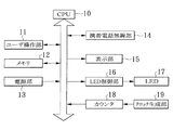
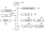
図1は、この発明の第1の実施例である携帯用電子機器の要部の電気的構成を示すブロック図である。
この例の携帯用電子機器は、同図に示すように、携帯電話機であり、CPU(中央処理装置)10と、ユーザ操作部11と、メモリ12と、電源部13と、携帯電話無線部14と、表示部15と、LED制御部16と、LED17と、カウンタ18と、クロック生成部19とから構成されている。ユーザ操作部11は、たとえば、送信キー、英字/カナ/漢字/数字の変換キー、電源のオン/オフキー、カーソル操作を行うための十文字キー、及び終了キーなどから構成され、ユーザにより、たとえば送信用のメッセージを作成するための操作が行われるなど、ユーザが操作を行うためのインタフェースとなる。
FIG. 1 is a block diagram showing the electrical configuration of the main part of a portable electronic device according to the first embodiment of the present invention.
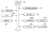
As shown in the figure, the portable electronic device in this example is a mobile phone, and includes a CPU (central processing unit) 10, a
メモリ12は、CPU10の制御プログラムを格納するROM(Read Only Memory、リードオンリメモリ)や、同CPU10のワークエリアとしての使用や一時的なユーザ設定を格納するためのRAM(Randam Access Memory、ランダムアクセスメモリ)から構成され、特に、この実施例では、同CPU10に携帯電話機を制御させるための点灯制御プログラムが記録されている。電源部13は、たとえばリチウムイオン電池などで構成され、当該携帯電話機全体に電源を供給する。携帯電話無線部14は、図示しない無線基地局との間で無線電波を送受信する。同無線基地局は、図示しない在圏移動通信交換局及び関門移動通信交換局を介して通常の電話回線に接続されている。表示部15は、たとえば液晶表示装置などで構成され、照明光により画面を表示する。
The
LED制御部16は、CPU10からの制御信号によりオン/オフ制御されるトランジスタなどで構成され、同CPU10による制御に基づいてLED17の点灯状態を制御する。LED17は、たとえば、ユーザ操作部11の各キーに内蔵されている。クロック生成部19は、当該携帯電話機の動作の基準となるクロックを生成する。カウンタ18は、クロックをカウントしてカウント値を生成する。CPU10は、当該携帯電話機全体を制御し、電源がオン状態のとき、カウンタ18からのカウント値を検出して時間を計測し、ユーザ操作部11に対して一定期間操作が行われない場合に表示部15の照明光を消灯して省電力状態へ移行する一方、所定時間経過後にLED制御部16を制御してLED17を点灯させることにより同電源がオン状態であることを通知する。また、CPU10は、電源部13の電池電圧を監視して同電池電圧に応じてLED17の点灯状態を制御し、特に、この実施例では、メモリ12に記録されている点灯制御プログラムに設定された点灯制御パラメータに基づいて、LED17が点灯する時間を同電池電圧に対応させて制御する。
The
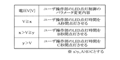
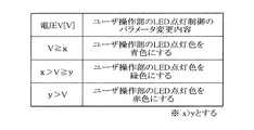
図2は、図1中のメモリ12に記録されている点灯制御プログラムにより設定された電池電圧と点灯制御パラメータとの関係を示す図である。
この点灯制御プログラムでは、同図2に示すように、電池電圧に基づいて電圧レベルが3つに分けられ、それぞれの電圧に応じて、LED17を点灯するための点灯制御パラメータが変更されるようになっている。すなわち、電池電圧V≧xのとき、LED17の点灯時間がA秒、電池電圧Vがx>V≧yのとき、LED17の点灯時間がB秒、及び、電池電圧Vがy>Vのとき、LED17の点灯時間がC秒に設定される。ただし、x>y、A>B>Cである。
FIG. 2 is a diagram showing the relationship between the battery voltage set by the lighting control program recorded in the
In this lighting control program, as shown in FIG. 2, the voltage level is divided into three based on the battery voltage, and the lighting control parameter for lighting the
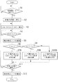
図3は、図1の携帯電話機の動作を説明するフローチャートである。
この図を参照して、この例の携帯電話機に用いられる点灯制御方法の処理内容について説明する。
この携帯電話機では、電池電圧に応じてLED17の点灯状態が制御され、特に、この実施例では、同LED17の点灯する時間が電池電圧に対応して制御される。
FIG. 3 is a flowchart for explaining the operation of the mobile phone of FIG.
With reference to this figure, the processing content of the lighting control method used for the mobile phone of this example will be described.
In this cellular phone, the lighting state of the
すなわち、電源がオン状態のとき、カウンタ18からのカウント値がCPU10で検出されて時間が計測され、ユーザ操作部11に対して一定期間操作が行われない場合(ステップS1)、同CPU10は、表示部15の照明光を消灯して省電力状態へ移行する(ステップS2)。この後、カウンタ18により、LED17をオン状態とするタイミング(ONタイミング)を検出するためのカウントが開始される(ステップS3)。そして、CPU10により、カウンタ18からのカウント値がONタイミングに対応する値になったことが判定され(ステップS4)、このとき、電池電圧のレベルが確認される(ステップS5)。
That is, when the power is on, the count value from the
この場合、電池電圧Vがx以上のとき(ステップS6)、CPU10により、LED17の1回の点灯時間がA秒に設定され、同LED17がA秒間点灯する(ステップS7)。また、ステップS6において、電池電圧Vがx未満かつy以上のとき(ステップS8)、LED17の1回の点灯時間がB秒に設定され、同LED17がB秒間点灯する(ステップS9)。また、ステップS8において、電池電圧Vがy未満のとき、LED17の1回の点灯時間がC秒に設定され、同LED17がC秒間点灯する(ステップS10)。LED17の点灯後、ステップS11において、省電力状態が継続していれば、ステップS3に戻り、カウンタ18は再度クロックのカウントを開始し、CPU10は、次回のONタイミングを待つ。一方、ステップS11において、省電力状態が継続していない場合、ステップS12に進み、CPU10により、電池電圧のレベルが確認されると共に、カウンタ18からのカウント値の検出が停止され、LED17の点灯制御が中止される。
In this case, when the battery voltage V is greater than or equal to x (step S6), the
以上のように、この第1の実施例では、電源がオン状態で表示部15の照明光が消灯された省電力状態でも、LED17の点灯時間が電池電圧に対応して制御されるので、電池残量を目視することが可能となる。また、電池電圧は、CPU10により常に把握されているパラメータの一つであるので、この実施例の制御を追加することによる消費電流の増加が殆どないため、電池寿命に対する影響は小さい。
As described above, in the first embodiment, the lighting time of the
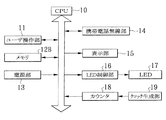
図4は、この発明の第2の実施例である携帯電話機の電気的構成を示すブロック図であり、第1の実施例を示す図1中の要素と共通の要素には共通の符号が付されている。
この例の携帯電話機では、同図4に示すように、図1中のメモリ12に代えて、異なる点灯制御プログラムが記録されたメモリ12Bが設けられている。この場合、CPU10は、メモリ12Bに記録されている点灯制御プログラムに設定された点灯制御パラメータに基づいて、LED17が点滅する回数を電池電圧に対応させて制御する。他は、図1と同様の構成である。
FIG. 4 is a block diagram showing an electrical configuration of a mobile phone according to a second embodiment of the present invention. Elements common to those in FIG. 1 showing the first embodiment are denoted by common reference numerals. Has been.
In the mobile phone of this example, as shown in FIG. 4, a
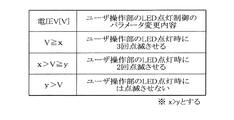
図5は、図4中のメモリ12Bに記録されている点灯制御プログラムにより設定された電池電圧と点灯制御パラメータとの関係を示す図である。
この点灯制御プログラムでは、同図5に示すように、電池電圧に基づいて電圧レベルが3つに分けられ、それぞれの電圧に応じて、LED17を点灯するための点灯制御パラメータが変更されるようになっている。すなわち、電池電圧V≧xのとき、LED17の点灯時に3回点滅、電池電圧Vがx>V≧yのとき、LED17の点灯時に2回点滅、及び、電池電圧Vがy>Vのとき、LED17の点灯時に点滅させないように設定される。ただし、x>yである。
FIG. 5 is a diagram showing the relationship between the battery voltage set by the lighting control program recorded in the
In this lighting control program, as shown in FIG. 5, the voltage level is divided into three based on the battery voltage, and the lighting control parameter for lighting the
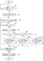
図6は、図4の携帯電話機の動作を説明するフローチャートである。
この図を参照して、この例の携帯電話機に用いられる点灯制御方法の処理内容について説明する。
この携帯電話機では、LED17の点滅する回数が電池電圧に対応して制御される。
すなわち、ステップS1乃至S6において、第1の実施例と同様の処理が行われ、ステップS6において、電池電圧Vがx以上のとき、CPU10により、LED17の点滅回数が3回に設定され、同LED17が3回点滅する(ステップS7B)。また、ステップS6において、電池電圧Vがx未満かつy以上のとき(ステップS8)、LED17の点滅回数が2回に設定され、同LED17が2回点滅する(ステップS9B)。また、ステップS8において、電池電圧Vがy未満のとき、LED17が一定期間点灯するように設定され、同LED17が一定期間点灯する(ステップS10B)。この後、第1の実施例と同様の処理が行われる。
FIG. 6 is a flowchart for explaining the operation of the mobile phone of FIG.
With reference to this figure, the processing content of the lighting control method used for the mobile phone of this example will be described.
In this mobile phone, the number of times the
That is, in steps S1 to S6, the same process as in the first embodiment is performed. In step S6, when the battery voltage V is equal to or higher than x, the
以上のように、この第2の実施例では、電源がオン状態で表示部15の照明光が消灯された省電力状態でも、LED17の点滅する回数が電池電圧に対応して制御されるので、電池残量を目視することが可能となる。
As described above, in the second embodiment, even when the power is on and the illumination light of the
図7は、この発明の第3の実施例である携帯電話機の電気的構成を示すブロック図であり、図1中の要素と共通の要素には共通の符号が付されている。
この例の携帯電話機では、同図7に示すように、図1中のメモリ12、LED制御部16及びLED17に代えて、異なる点灯制御プログラムが記録されたメモリ12C、異なる構成のLED制御部16C及び3色LED17Cが設けられている。3色LED17Cは、赤,緑,青の3色のLEDが1チップに内蔵されて構成されている。LED制御部16Cは、CPU10からの制御信号によりオン/オフ制御されるトランジスタなどで構成され、同CPU10による制御に基づいて3色LED17Cの点灯状態を各色毎に制御する。CPU10は、メモリ12Cに記録されている点灯制御プログラムに設定された点灯制御パラメータに基づいて、3色LED17Cが発光する色を電池電圧に対応させて制御する。他は、図1と同様の構成である。
FIG. 7 is a block diagram showing an electrical configuration of a mobile phone according to a third embodiment of the present invention. Elements common to those in FIG. 1 are denoted by common reference numerals.
In the cellular phone of this example, as shown in FIG. 7, instead of the
図8は、図7中のメモリ12Cに記録されている点灯制御プログラムにより設定された電池電圧と点灯制御パラメータとの関係を示す図である。
この点灯制御プログラムでは、同図8に示すように、電池電圧に基づいて電圧レベルが3つに分けられ、それぞれの電圧に応じて、3色LED17Cを点灯するための点灯制御パラメータが変更されるようになっている。すなわち、電池電圧V≧xのとき、3色LED17Cの青が点灯、電池電圧Vがx>V≧yのとき、3色LED17Cの緑が点灯、及び、電池電圧Vがy>Vのとき、3色LED17Cの赤が点灯するように設定される。ただし、x>yである。
FIG. 8 is a diagram showing the relationship between the battery voltage set by the lighting control program recorded in the
In this lighting control program, as shown in FIG. 8, the voltage level is divided into three based on the battery voltage, and the lighting control parameter for lighting the three-
図9は、図7の携帯電話機の動作を説明するフローチャートである。
この図を参照して、この例の携帯電話機に用いられる点灯制御方法の処理内容について説明する。
この携帯電話機では、3色LED17Cの発光する色が電池電圧に対応して制御される。
すなわち、ステップS1乃至S6において、第1の実施例と同様の処理が行われ、ステップS6において、電池電圧Vがx以上のとき、CPU10により、3色LED17Cの発光する色が青に設定され、同3色LED17Cが青色に発光する(ステップS7C)。また、ステップS6において、電池電圧Vがx未満かつy以上のとき(ステップS8)、3色LED17Cの発光する色が緑に設定され、同3色LED17Cが緑色に発光する(ステップS9C)。また、ステップS8において、電池電圧Vがy未満のとき、3色LED17Cの発光する色が赤に設定され、同3色LED17Cが赤色に発光する(ステップS10C)。この後、第1の実施例と同様の処理が行われる。
FIG. 9 is a flowchart for explaining the operation of the mobile phone of FIG.
With reference to this figure, the processing content of the lighting control method used for the mobile phone of this example will be described.
In this cellular phone, the color emitted by the three-
That is, in steps S1 to S6, the same process as in the first embodiment is performed. In step S6, when the battery voltage V is equal to or greater than x, the
以上のように、この第3の実施例では、電源がオン状態で表示部15の照明光が消灯された省電力状態でも、3色LED17Cの発光する色が電池電圧に対応して制御されるので、電池残量を目視することが可能となる。
As described above, in the third embodiment, even when the power is on and the illumination light of the
図10は、この発明の第4の実施例である携帯電話機の電気的構成を示すブロック図であり、第1の実施例を示す図1中の要素と共通の要素には共通の符号が付されている。
この例の携帯電話機では、同図10に示すように、図1中のメモリ12に代えて、異なる点灯制御プログラムが記録されたメモリ12Dが設けられている。この場合、CPU10は、メモリ12Dに記録されている点灯制御プログラムに設定された点灯制御パラメータに基づいて、LED17を断続的に点灯させ、かつ点灯の時間間隔を電池電圧に対応させて制御する。他は、図1と同様の構成である。
FIG. 10 is a block diagram showing an electrical configuration of a cellular phone according to a fourth embodiment of the present invention. Elements common to those in FIG. 1 showing the first embodiment are denoted by common reference numerals. Has been.
In the mobile phone of this example, as shown in FIG. 10, a
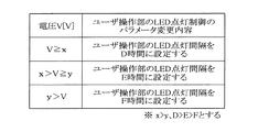
図11は、図10中のメモリ12Dに記録されている点灯制御プログラムにより設定された電池電圧と点灯制御パラメータとの関係を示す図である。
この点灯制御プログラムでは、同図11に示すように、電池電圧に基づいて電圧レベルが3つに分けられ、それぞれの電圧に応じて、LED17を点灯するための点灯制御パラメータが変更されるようになっている。すなわち、電池電圧V≧xのとき、LED17の点灯の時間間隔がD時間、電池電圧Vがx>V≧yのとき、LED17の点灯の時間間隔がE時間、及び、電池電圧Vがy>Vのとき、LED17の点灯の時間間隔がF時間となるように設定される。ただし、x>y、D>E>Fである。
FIG. 11 is a diagram showing the relationship between the battery voltage set by the lighting control program recorded in the
In this lighting control program, as shown in FIG. 11, the voltage level is divided into three based on the battery voltage, and the lighting control parameter for lighting the
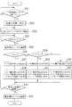
図12は、図10の携帯電話機の動作を説明するフローチャートである。
この図を参照して、この例の携帯電話機に用いられる点灯制御方法の処理内容について説明する。
この携帯電話機では、LED17が断続的に点灯され、かつ点灯の時間間隔が電池電圧に対応して制御される。すなわち、ステップS21乃至S26において、第1の実施例のS1乃至S6と同様の処理が行われ、ステップS26において、電池電圧Vがx以上のとき、ステップS27に進み、LED17が一定期間点灯し、次に点灯するONタイミングまでの間隔がD時間に設定され、次のONタイミングを待つ(ステップS28)。また、ステップS26において、電池電圧Vがx未満かつy以上のとき(ステップS29)、LED17が一定期間点灯し、次に点灯するONタイミングまでの間隔がE時間に設定され、次のONタイミングを待つ(ステップS31)。また、ステップS29において、電池電圧Vがy未満のとき、LED17が一定期間点灯し、次に点灯するONタイミングまでの間隔がF時間に設定され、次のONタイミングを待つ(ステップS33)。この後、ステップS34乃至S35において、第1の実施例のS11乃至S12と同様の処理が行われる。
FIG. 12 is a flowchart for explaining the operation of the mobile phone of FIG.
With reference to this figure, the processing content of the lighting control method used for the mobile phone of this example will be described.
In this mobile phone, the
以上のように、この第4の実施例では、電源がオン状態で表示部15の照明光が消灯された省電力状態でも、LED17の点灯の時間間隔が電池電圧に対応して制御されるので、電池残量を目視することが可能となる。
As described above, in the fourth embodiment, even when the power is on and the illumination light of the
以上、この発明の実施例を図面により詳述してきたが、具体的な構成は同実施例に限られるものではなく、この発明の要旨を逸脱しない範囲の設計の変更などがあっても、この発明に含まれる。
たとえば、上記各実施例では、電池電圧Vが、x以上、x未満y以上、及びy未満の3つの電圧レベルに分けられているが、3つに限定されず、任意数の電圧レベルに分けても良い。また、表示部15は、液晶表示装置の他、自己発光により画面を表示するEL(エレクトロルミネセンス)などで構成しても良い。また、LED17及び3色LED17Cは、ユーザ操作部11の各キーに内蔵する他、たとえば、同各キーの近傍に設けても良い。
The embodiment of the present invention has been described in detail with reference to the drawings. However, the specific configuration is not limited to the embodiment, and even if there is a design change without departing from the gist of the present invention, Included in the invention.
For example, in each of the above embodiments, the battery voltage V is divided into three voltage levels of x or more, less than x, y or more, and less than y, but is not limited to three and is divided into any number of voltage levels. May be. In addition to the liquid crystal display device, the
また、第3の実施例では、電池電圧Vのレベルに応じて、青、緑、又は赤のLEDが点灯するようになっているが、複数の色のLEDを選択して同時に点灯し、加法混色により、マゼンタ、白、黄、又はシアンとして点灯しても良い。また、電源部13は、リチウムイオン電池に限らず、一次電池や燃料電池などで構成しても良い。また、第4の実施例では、第2の実施例を組み合わせることにより、点灯するLED17を点滅制御するようにしても良い。また、第3の実施例に第4の実施例を組み合わせることにより、3色LED17Cの点灯する時間間隔が電池電圧に対応して制御するようにしても良い。
Further, in the third embodiment, blue, green, or red LEDs are lit according to the level of the battery voltage V, but a plurality of color LEDs are selected and lit at the same time. Depending on the color mixture, it may be lit as magenta, white, yellow, or cyan. The
この発明は、携帯電話機の他、PDA(Personal Digital Assistants )やノート型パソコンなど、電源部に電池を有する携帯用電子機器全般に適用できる。 The present invention can be applied to all portable electronic devices having a battery in the power supply unit such as PDAs (Personal Digital Assistants) and notebook personal computers in addition to cellular phones.
10 CPU(中央処理装置、点灯制御手段の一部)
11 ユーザ操作部(操作部)
12,12B,12C,12D メモリ(点灯制御手段の一部)
13 電源部
14 携帯電話無線部
15 表示部
16,16C LED制御部(点灯制御手段の一部)
17 LED(発光ダイオード、発光部)
17C 3色LED(発光部)
18 カウンタ
19 クロック生成部
10 CPU (central processing unit, part of lighting control means)
11 User operation unit (operation unit)
12, 12B, 12C, 12D Memory (part of lighting control means)
13 power supply unit 14 mobile
17 LED (light emitting diode, light emitting part)
17C 3-color LED (light emitting part)
18
Claims (11)
発光部と、
照明光又は自己発光により画面を表示する表示部と、
電池を有する電源部とを備え、
電源がオン状態のときに前記操作部に対して一定期間操作が行われない場合に前記表示部の照明光又は自己発光を消灯して省電力状態へ移行する一方、前記発光部を点灯させることにより前記電源がオン状態であることを通知する携帯用電子機器であって、
前記電池の電圧に応じて前記発光部の点灯状態を制御する点灯制御手段が設けられていることを特徴とする携帯用電子機器。 An operation unit;
A light emitting unit;
A display unit for displaying a screen by illumination light or self-emission;
A power supply unit having a battery,
When the operation unit is not operated for a certain period of time when the power is on, the illumination light or self-emission of the display unit is turned off to shift to the power saving state, and the light emitting unit is turned on. A portable electronic device for notifying that the power is on by
A portable electronic device comprising a lighting control means for controlling a lighting state of the light emitting unit in accordance with a voltage of the battery.
前記発光部が点灯する時間を前記電池の電圧に対応させて制御する構成とされていることを特徴とする請求項1記載の携帯用電子機器。 The lighting control means includes
The portable electronic device according to claim 1, wherein a time during which the light emitting unit is lit is controlled in accordance with a voltage of the battery.
前記発光部が点滅する回数を前記電池の電圧に対応させて制御する構成とされていることを特徴とする請求項1記載の携帯用電子機器。 The lighting control means includes
The portable electronic device according to claim 1, wherein the number of times the light emitting unit blinks is controlled in accordance with the voltage of the battery.
複数の色を発光する構成とされ、
前記点灯制御手段は、
前記発光部が発光する色を前記電池の電圧に対応させて制御する構成とされていることを特徴とする請求項1記載の携帯用電子機器。 The light emitting unit
It is configured to emit multiple colors,
The lighting control means includes
The portable electronic device according to claim 1, wherein a color emitted from the light emitting unit is controlled in accordance with a voltage of the battery.
前記発光部を断続的に点灯させ、かつ該点灯の時間間隔を前記電池の電圧に対応させて制御する構成とされていることを特徴とする請求項1記載の携帯用電子機器。 The lighting control means includes
The portable electronic device according to claim 1, wherein the light emitting unit is intermittently turned on, and the lighting time interval is controlled in accordance with the voltage of the battery.
前記電池の電圧に応じて前記発光部の点灯状態を制御することを特徴とする点灯制御方法。 An operation unit, a light emitting unit, a display unit that displays a screen by illumination light or self-emission, and a power source unit having a battery are provided, and the operation unit is operated for a certain period of time when the power is on. When not present, the illumination light or self-light emission of the display unit is turned off to shift to a power saving state, while the light emitting unit is turned on to be used for a portable electronic device that notifies that the power source is in an on state ,
A lighting control method, comprising: controlling a lighting state of the light emitting unit according to a voltage of the battery.
前記発光部が発光する色を前記電池の電圧に対応させて制御することを特徴とする請求項6記載の点灯制御方法。 The light emitting unit is configured to emit a plurality of colors,
The lighting control method according to claim 6, wherein a color emitted by the light emitting unit is controlled in accordance with a voltage of the battery.
Priority Applications (4)
| Application Number | Priority Date | Filing Date | Title |
|---|---|---|---|
| JP2004358504A JP2006166350A (en) | 2004-12-10 | 2004-12-10 | Portable electronic apparatus, lighting control method used therefor and lighting control program |
| US11/292,106 US20060128446A1 (en) | 2004-12-10 | 2005-12-02 | Portable electronic device, lighting control method used for the same, and program product |
| EP05026640A EP1670220A1 (en) | 2004-12-10 | 2005-12-06 | Portable electronic device, corresponding method for battery status indication by means of a lighting unit and related program product |
| CNA2005101301346A CN1787574A (en) | 2004-12-10 | 2005-12-12 | Portable electronic device, lighting control method used for the same, and program product |
Applications Claiming Priority (1)
| Application Number | Priority Date | Filing Date | Title |
|---|---|---|---|
| JP2004358504A JP2006166350A (en) | 2004-12-10 | 2004-12-10 | Portable electronic apparatus, lighting control method used therefor and lighting control program |
Publications (1)
| Publication Number | Publication Date |
|---|---|
| JP2006166350A true JP2006166350A (en) | 2006-06-22 |
Family
ID=35871247
Family Applications (1)
| Application Number | Title | Priority Date | Filing Date |
|---|---|---|---|
| JP2004358504A Pending JP2006166350A (en) | 2004-12-10 | 2004-12-10 | Portable electronic apparatus, lighting control method used therefor and lighting control program |
Country Status (4)
| Country | Link |
|---|---|
| US (1) | US20060128446A1 (en) |
| EP (1) | EP1670220A1 (en) |
| JP (1) | JP2006166350A (en) |
| CN (1) | CN1787574A (en) |
Cited By (5)
| Publication number | Priority date | Publication date | Assignee | Title |
|---|---|---|---|---|
| JP2008009009A (en) * | 2006-06-28 | 2008-01-17 | Korg Inc | Effect adding device |
| JP2008165520A (en) * | 2006-12-28 | 2008-07-17 | Kyocera Mita Corp | Power-saving mode display method and power-saving mode display device for image forming device |
| JP2009244772A (en) * | 2008-03-31 | 2009-10-22 | Yamatake Corp | Liquid crystal display |
| JP2009303058A (en) * | 2008-06-16 | 2009-12-24 | Nec Saitama Ltd | Portable information terminal, display-power control method, and display-power control program |
| JP2011530790A (en) * | 2008-08-08 | 2011-12-22 | マグ インスツルメント インコーポレーテッド | Portable lighting device |
Families Citing this family (11)
| Publication number | Priority date | Publication date | Assignee | Title |
|---|---|---|---|---|
| CN101018077A (en) * | 2006-02-10 | 2007-08-15 | 朗迅科技公司 | Power-saving method of the mobile terminal |
| KR101633329B1 (en) * | 2009-08-19 | 2016-06-24 | 엘지전자 주식회사 | Mobile terminal and method for controlling therof |
| CN102143276A (en) * | 2010-12-29 | 2011-08-03 | 上海华勤通讯技术有限公司 | Electricity-saving energy-saving electronic device and electricity-saving energy-saving method thereof |
| CN102681638A (en) * | 2011-03-10 | 2012-09-19 | 深圳立讯精密工业股份有限公司 | Light-emitting device and application of light-emitting device to displaying notebook power |
| US8853966B2 (en) * | 2011-06-22 | 2014-10-07 | Panasonic Corporation | Lighting device and illumination apparatus including same |
| CN103631356B (en) * | 2012-08-20 | 2019-01-15 | 联想(北京)有限公司 | A kind of method and electronic equipment of economize on electricity |
| CN102929382A (en) * | 2012-10-24 | 2013-02-13 | 惠州Tcl移动通信有限公司 | Method for reducing power consumption of electronic equipment and electronic equipment |
| CN104968117B (en) * | 2015-07-13 | 2017-10-13 | 佛山市顺德区美的洗涤电器制造有限公司 | A kind of dish-washing machine and its three primary colours prompting control method and device |
| CN106445757A (en) * | 2016-09-29 | 2017-02-22 | 郑州云海信息技术有限公司 | Central processing unit (CPU) fault location method and device |
| JP6622782B2 (en) * | 2017-11-24 | 2019-12-18 | ファナック株式会社 | Control device, electronic device, and control system |
| JP6693540B2 (en) * | 2018-07-31 | 2020-05-13 | 横河電機株式会社 | Device, method and program |
Family Cites Families (9)
| Publication number | Priority date | Publication date | Assignee | Title |
|---|---|---|---|---|
| SE517491C2 (en) * | 1997-06-06 | 2002-06-11 | Ericsson Telefon Ab L M | Mobile Phone Device |
| US6278887B1 (en) * | 1999-02-05 | 2001-08-21 | Neopoint, Inc. | System and method for power conservation in a wireless communication handset |
| FI115801B (en) * | 1999-05-27 | 2005-07-15 | Nokia Corp | display Control |
| JP3524827B2 (en) * | 1999-09-30 | 2004-05-10 | 三洋電機株式会社 | Battery level indicator for telephone |
| JP4024444B2 (en) * | 1999-12-27 | 2007-12-19 | 株式会社東芝 | Wireless telephone equipment |
| JP3448003B2 (en) * | 2000-03-09 | 2003-09-16 | 株式会社東芝 | Mobile communication terminal |
| JP2003101643A (en) * | 2001-09-21 | 2003-04-04 | Sharp Corp | Portable wireless communication equipment |
| US7120471B2 (en) * | 2003-02-28 | 2006-10-10 | Nokia Corporation | User interface and associated method for indicating status using keypad backlights |
| US7065664B2 (en) * | 2003-03-18 | 2006-06-20 | Inventec Appliances Corp. | Power management for a PDA system |
-
2004
- 2004-12-10 JP JP2004358504A patent/JP2006166350A/en active Pending
-
2005
- 2005-12-02 US US11/292,106 patent/US20060128446A1/en not_active Abandoned
- 2005-12-06 EP EP05026640A patent/EP1670220A1/en not_active Withdrawn
- 2005-12-12 CN CNA2005101301346A patent/CN1787574A/en active Pending
Cited By (5)
| Publication number | Priority date | Publication date | Assignee | Title |
|---|---|---|---|---|
| JP2008009009A (en) * | 2006-06-28 | 2008-01-17 | Korg Inc | Effect adding device |
| JP2008165520A (en) * | 2006-12-28 | 2008-07-17 | Kyocera Mita Corp | Power-saving mode display method and power-saving mode display device for image forming device |
| JP2009244772A (en) * | 2008-03-31 | 2009-10-22 | Yamatake Corp | Liquid crystal display |
| JP2009303058A (en) * | 2008-06-16 | 2009-12-24 | Nec Saitama Ltd | Portable information terminal, display-power control method, and display-power control program |
| JP2011530790A (en) * | 2008-08-08 | 2011-12-22 | マグ インスツルメント インコーポレーテッド | Portable lighting device |
Also Published As
| Publication number | Publication date |
|---|---|
| CN1787574A (en) | 2006-06-14 |
| US20060128446A1 (en) | 2006-06-15 |
| EP1670220A1 (en) | 2006-06-14 |
Similar Documents
| Publication | Publication Date | Title |
|---|---|---|
| JP2006166350A (en) | Portable electronic apparatus, lighting control method used therefor and lighting control program | |
| FI115801B (en) | display Control | |
| US7102632B2 (en) | Method for saving power in an organic electroluminescent display | |
| US20180024619A1 (en) | Display device, display control method, and computer-readable storage medium | |
| US6967647B2 (en) | Method of controlling display brightness of portable information device, and portable information device | |
| US20040075700A1 (en) | Functional idle mode display | |
| US20020186214A1 (en) | Method for saving power in an organic electroluminescent display using white light emitting elements | |
| WO2015070612A1 (en) | Terminal display control method and terminal | |
| CN107318196B (en) | Indicator lamp circuit of mobile terminal and control method thereof | |
| WO2012035809A1 (en) | Portable terminal, method for controlling same, and program | |
| US20110063276A1 (en) | Methods, Systems, Devices and Components for Reducing Power Consumption in an LCD Backlit by LEDs | |
| KR20130025228A (en) | A mobile communication device having an all-time status displaying icon group and the method of it | |
| CN105677544B (en) | Lamplight display method and light display apparatus | |
| JP4196622B2 (en) | Color balance adjusting device and electronic device | |
| AU749391B2 (en) | Mobile telephone set | |
| JP2001273055A (en) | Portable information processing apparatus and system activation method for the same | |
| KR101872031B1 (en) | Display device | |
| US20020024480A1 (en) | Portable information terminal apparatus | |
| CN100504999C (en) | Display apparatus and display control method | |
| JP2004198809A (en) | Method for driving spontaneous light emission type display and battery driven type information display device | |
| JP2004274570A (en) | Control method of key backlight in portable device | |
| EP1622343B1 (en) | Portable radio terminal | |
| CN112188663B (en) | Breathing lamp module, electronic equipment and preparation method thereof | |
| WO2007063835A1 (en) | Portable electronic device and its control method, and portable terminal and its display method | |
| JP2006030566A (en) | Electronic apparatus equipped with display panel |
Legal Events
| Date | Code | Title | Description |
|---|---|---|---|
| A621 | Written request for application examination |
Free format text: JAPANESE INTERMEDIATE CODE: A621 Effective date: 20071112 |
|
| A977 | Report on retrieval |
Free format text: JAPANESE INTERMEDIATE CODE: A971007 Effective date: 20081222 |
|
| A131 | Notification of reasons for refusal |
Free format text: JAPANESE INTERMEDIATE CODE: A131 Effective date: 20090106 |
|
| A521 | Request for written amendment filed |
Free format text: JAPANESE INTERMEDIATE CODE: A523 Effective date: 20090309 |
|
| A131 | Notification of reasons for refusal |
Free format text: JAPANESE INTERMEDIATE CODE: A131 Effective date: 20090630 |
|
| A02 | Decision of refusal |
Free format text: JAPANESE INTERMEDIATE CODE: A02 Effective date: 20091201 |