JP2006166316A - Optical path rearrangement method in optical communication network - Google Patents
Optical path rearrangement method in optical communication network Download PDFInfo
- Publication number
- JP2006166316A JP2006166316A JP2004358076A JP2004358076A JP2006166316A JP 2006166316 A JP2006166316 A JP 2006166316A JP 2004358076 A JP2004358076 A JP 2004358076A JP 2004358076 A JP2004358076 A JP 2004358076A JP 2006166316 A JP2006166316 A JP 2006166316A
- Authority
- JP
- Japan
- Prior art keywords
- optical
- transition
- optical path
- evaluation value
- stage
- Prior art date
- Legal status (The legal status is an assumption and is not a legal conclusion. Google has not performed a legal analysis and makes no representation as to the accuracy of the status listed.)
- Granted
Links
- 230000003287 optical effect Effects 0.000 title claims abstract description 305
- 238000000034 method Methods 0.000 title claims abstract description 106
- 238000004891 communication Methods 0.000 title claims abstract description 36
- 230000008707 rearrangement Effects 0.000 title claims abstract description 15
- 238000011156 evaluation Methods 0.000 claims abstract description 135
- 230000008569 process Effects 0.000 claims abstract description 67
- 238000013508 migration Methods 0.000 claims abstract description 27
- 230000005012 migration Effects 0.000 claims abstract description 27
- 239000013307 optical fiber Substances 0.000 claims abstract description 11
- 230000007704 transition Effects 0.000 claims description 205
- 238000012854 evaluation process Methods 0.000 claims description 49
- 238000012545 processing Methods 0.000 abstract description 20
- 230000004044 response Effects 0.000 abstract description 10
- 230000005540 biological transmission Effects 0.000 description 17
- 238000010586 diagram Methods 0.000 description 17
- 230000008859 change Effects 0.000 description 10
- 238000012546 transfer Methods 0.000 description 8
- 238000004364 calculation method Methods 0.000 description 7
- 230000006870 function Effects 0.000 description 5
- 238000012544 monitoring process Methods 0.000 description 3
- 230000007274 generation of a signal involved in cell-cell signaling Effects 0.000 description 2
- 230000000694 effects Effects 0.000 description 1
- 238000002474 experimental method Methods 0.000 description 1
- 230000002068 genetic effect Effects 0.000 description 1
- 238000007562 laser obscuration time method Methods 0.000 description 1
- 230000007774 longterm Effects 0.000 description 1
- 238000005457 optimization Methods 0.000 description 1
- 238000004321 preservation Methods 0.000 description 1
Images


Classifications
-
- H—ELECTRICITY
- H04—ELECTRIC COMMUNICATION TECHNIQUE
- H04J—MULTIPLEX COMMUNICATION
- H04J14/00—Optical multiplex systems
- H04J14/02—Wavelength-division multiplex systems
- H04J14/0227—Operation, administration, maintenance or provisioning [OAMP] of WDM networks, e.g. media access, routing or wavelength allocation
- H04J14/0241—Wavelength allocation for communications one-to-one, e.g. unicasting wavelengths
-
- H—ELECTRICITY
- H04—ELECTRIC COMMUNICATION TECHNIQUE
- H04J—MULTIPLEX COMMUNICATION
- H04J14/00—Optical multiplex systems
- H04J14/02—Wavelength-division multiplex systems
- H04J14/0278—WDM optical network architectures
- H04J14/0284—WDM mesh architectures
Landscapes
- Engineering & Computer Science (AREA)
- Computer Networks & Wireless Communication (AREA)
- Signal Processing (AREA)
- Data Exchanges In Wide-Area Networks (AREA)
- Optical Communication System (AREA)
Abstract
Description
この発明は、光通信ネットワークにおける光パス再配置方法に関するものである。 The present invention relates to an optical path relocation method in an optical communication network.
光通信ネットワークは、複数のルータ、複数の光スイッチ、ルータと光スイッチを接続するか又は2つの光スイッチ間を接続する光ファイバ、及び、管理装置を備えている。この光通信ネットワークでは、パケットの伝送量を高めるために動的に光通信ネットワーク全体の光パスの配置(以下、単に光パス配置と称する。)を移行する、すなわち光パス配置を再配置することが提案されている(例えば、非特許文献1及び2参照)。 The optical communication network includes a plurality of routers, a plurality of optical switches, an optical fiber connecting the router and the optical switch, or connecting two optical switches, and a management device. In this optical communication network, in order to increase the amount of packet transmission, the optical path arrangement of the entire optical communication network (hereinafter simply referred to as optical path arrangement) is dynamically shifted, that is, the optical path arrangement is rearranged. Has been proposed (see, for example, Non-Patent Documents 1 and 2).
現在用いている光パス配置(以下、単に現用パス配置と称する。)から最適な光パス配置(以下、単に最適パス配置と称する。)への移行は、例えば、光通信ネットワークに備えられる光スイッチを切り換えるとともに、ルータの設定を切り換えて、個々の光パスを変更することにより、最適な光パス配置への移行が行われる。 The transition from the currently used optical path arrangement (hereinafter simply referred to as the working path arrangement) to the optimum optical path arrangement (hereinafter simply referred to as the optimal path arrangement) is, for example, an optical switch provided in the optical communication network. And switching the router settings to change individual optical paths, thereby shifting to an optimal optical path arrangement.
光通信ネットワーク全体について、現用パス配置から最適パス配置へ移行する方法として、例えば、変更が必要な光パスの全てを一度に解除し、解除の結果得られたネットワーク資源を利用して、新たな光パスを配置する方法がある。又は、変更が必要な光パスの半数を一度に解除し、解除の結果得られたネットワーク資源を利用して、新たな光パスを配置し、その後、残りの半数を一度に解除した後、新たな光パスを配置することによって、現用パス配置から最適パス配置への移行を行う方法もある(非特許文献2参照)。
しかしながら、上述の従来例の光通信ネットワークにおける光パス再配置方法では、光パス配置の移行の際に、一時的に利用可能なネットワーク資源が減少する。すなわち、変更が必要な光パスを解除する際には、光パスを伝送しているパケットは、別の光パスに振り替えられるため、当該別の光パスやルータにおいて輻輳等が起こり、パケットの損失が起こる恐れがある。 However, in the above-described conventional optical path relocation method in the optical communication network, the network resources that can be temporarily used are reduced when the optical path allocation is changed. In other words, when releasing an optical path that needs to be changed, packets that are transmitted through the optical path are transferred to another optical path, so congestion occurs in the other optical path or router and packet loss occurs. May happen.
光パス配置の移行には、1段階で行う方法及び2段階で行う方法の2通りの方法が行われている。ここで、光パス配置の移行を1段階で行うとは、変更が必要な光パスの全てを一度に解除した後、新たな光パスを設定することをいう。また、光パス配置の移行を2段階で行うとは、変更が必要な光パスを2つのグループに分け、最初に一方のグループの光パスを一度に解除した後、新たな光パスを設定し、さらに、他方のグループの光パスを一度に解除して、新たな光パスを設定することをいう。 There are two methods for shifting the optical path arrangement: a method performed in one step and a method performed in two steps. Here, performing the transition of the optical path arrangement in one stage means setting a new optical path after canceling all the optical paths that need to be changed at once. In addition, when the optical path arrangement is changed in two stages, the optical paths that need to be changed are divided into two groups, and after first releasing the optical path of one group at a time, a new optical path is set. Further, it means that the optical path of the other group is canceled at a time and a new optical path is set.
光パス配置の移行を1段階で行う場合と、2段階で行う場合とでどちらの方法が、パケット損失量が少ないかは、光通信ネットワークの構成及びトラフィック等のネットワークの状態に依存する。1段階で移行する場合は、移行に必要な時間が短いが、移行中に使用できる光パスが減ってしまう。また、2段階で移行する場合は、移行中に使用できる光パスは1段階で移行する場合よりも多いため、パケットの損失は生じにくい。しかし、移行に必要な時間が1段階で移行する場合よりも長くなるため、結果としてパケットの損失量が多くなる場合がある。 Which of the methods in which the optical path arrangement transition is performed in one step and the two steps is small depends on the configuration of the optical communication network and the state of the network such as traffic. In the case of migration in one stage, the time required for migration is short, but the number of optical paths that can be used during migration is reduced. In the case of shifting in two stages, there are more optical paths that can be used during the transition than in the case of shifting in one stage, so packet loss is less likely to occur. However, since the time required for the migration is longer than when the migration is performed in one stage, the packet loss amount may increase as a result.
従来の光通信ネットワークにおける光パス再配置方法では、ネットワークの状態に応じて、パス配置の移行を1段階で移行を行うか、2段階で移行を行うかを判断する手法が無かったため、パケットの損失量が少ない最適な方法で光パス配置の移行を行うことができなかった。 In the conventional optical path rearrangement method in the optical communication network, there is no method for determining whether the path placement transition is performed in one step or two steps depending on the state of the network. The optical path arrangement could not be shifted by an optimum method with a small amount of loss.
この発明は、上述の問題点に鑑みてなされたものであり、この発明の目的は、光通信ネットワークの状態に応じて、パス配置の移行を1段階で移行を行うか、2段階で移行を行うかを判断することによって、パス配置の移行時にパケットの損失量を減らすことができる光通信ネットワークにおける光パス再配置方法を提供することにある。 The present invention has been made in view of the above-described problems, and an object of the present invention is to perform path transition transition in one stage or transition in two stages according to the state of the optical communication network. It is an object of the present invention to provide an optical path relocation method in an optical communication network that can reduce the amount of packet loss at the time of path allocation transition by determining whether to perform the path allocation.
上述した目的を達成するために、この発明の光通信ネットワークにおける光パス再配置方法は、複数のルータと、複数の光スイッチと、ルータ及び光スイッチ間又は光スイッチ同士間を接続する光ファイバ、管理装置とを備える光通信ネットワークで実施され、以下の過程を備えている。 In order to achieve the above-described object, an optical path relocation method in an optical communication network of the present invention includes a plurality of routers, a plurality of optical switches, an optical fiber connecting between the router and the optical switch, or between the optical switches, This is implemented in an optical communication network including a management device, and includes the following processes.
先ず、1段階パケット損失評価過程において、1段階移行により光パス配置を変更する際のパケット損失量を評価して第1評価値を求める。次に、第1評価値記録過程において、第1評価値を記憶装置に記録した後、2段階移行評価過程を行う。2段階移行評価過程は、第1次移行光パス選択過程及び2段階パケット損失評価過程を含んでいる。第1次移行光パス選択過程において、第1次移行及び第2次移行の2段階移行により光パス配置を変更する際に、変更する光パス群を二分した一方の光パス群を第1次移行光パスとして選択し、他方の光パス群を第2次移行光パスとする。その後、2段階パケット損失評価過程において、2段階移行により光パス配置を変更する際のパケット損失量を評価して第2評価値とする。次に、比較過程において、第2評価値を第1評価値と比較して、第2評価値が第1評価値よりも小さい場合は、第1評価値を、第2評価値で置き換えた後、第1評価値と、第1次及び第2次移行光パスを記憶装置に記録する。 First, in the one-stage packet loss evaluation process, the first evaluation value is obtained by evaluating the packet loss amount when the optical path arrangement is changed by the one-stage transition. Next, in the first evaluation value recording process, after the first evaluation value is recorded in the storage device, a two-stage transition evaluation process is performed. The two-stage transition evaluation process includes a first-order transition optical path selection process and a two-stage packet loss evaluation process. In the primary transition optical path selection process, when the optical path arrangement is changed by the two-stage transition of the primary transition and the secondary transition, one of the optical path groups that bisects the optical path group to be changed is the first order. The optical path group is selected as the transition optical path, and the other optical path group is set as the second transition optical path. Thereafter, in the two-stage packet loss evaluation process, the amount of packet loss when the optical path arrangement is changed by the two-stage transition is evaluated to obtain a second evaluation value. Next, in the comparison process, the second evaluation value is compared with the first evaluation value. If the second evaluation value is smaller than the first evaluation value, the first evaluation value is replaced with the second evaluation value. The first evaluation value and the primary and secondary transition light paths are recorded in the storage device.
予め記憶装置に記録されている処理終了条件を読み出してきて、処理終了条件を満たすまで、2段階移行評価過程、及び比較過程を繰り返し行う。 The process end condition recorded in advance in the storage device is read, and the two-stage transition evaluation process and the comparison process are repeated until the process end condition is satisfied.
上述した光通信ネットワークにおける光パス再配置方法の実施にあたり、好ましくは、第1次移行光パス選択過程において、複数の第1次移行パス及び第2次移行パスの組を同時に選択し、及び、2段階パケット損失評価過程において、選択された複数の第1次移行パス及び第2次移行パスの組のそれぞれに関するパケット損失量を同時に求めて、求められた複数のパケット損失量の中で最も小さいパケット損失量を第2評価値とするのが良い。 In implementing the optical path relocation method in the optical communication network described above, preferably, in the primary migration optical path selection process, a plurality of primary migration paths and secondary migration path sets are simultaneously selected, and In the two-stage packet loss evaluation process, the packet loss amount for each of the selected plurality of primary migration path and secondary migration path sets is simultaneously obtained, and the smallest of the obtained plurality of packet loss amounts. The packet loss amount may be set as the second evaluation value.
上述した光通信ネットワークにおける光パス再配置方法の実施にあたり、第1次移行光パス選択過程では、保存結果を得たパスの近傍解と、局所最適脱出解を、第1次移行光パスとして選択するのが好適である。 When implementing the optical path rearrangement method in the optical communication network described above, in the first-order transition optical path selection process, the neighborhood solution and the local optimal escape solution obtained as the preservation results are selected as the first-order transition optical paths. It is preferable to do this.
また、この発明の光通信ネットワークにおける光パス再配置方法は、複数のルータと、複数の光スイッチと、ルータ及び光スイッチ間又は光スイッチ同士間を接続する光ファイバと、管理装置とを備える光通信ネットワークで実施され、以下の過程を備えている。 An optical path relocation method in an optical communication network according to the present invention includes a plurality of routers, a plurality of optical switches, an optical fiber connecting between the routers and the optical switches or between the optical switches, and a management device. It is implemented in a communication network and includes the following processes.
先ず、1段階パケット損失評価過程において、1段階移行により光パス配置を変更する際のパケット損失量を評価して第1評価値を求める。次に、第1評価値記録過程において、第1評価値を記憶装置に記録した後に、N(但し、Nは2以上の整数)段階移行過程を行う。N段階移行過程は、第1〜N−1次移行光パス選択過程、及びN段階移行評価過程を備えている。 First, in the one-stage packet loss evaluation process, the first evaluation value is obtained by evaluating the packet loss amount when the optical path arrangement is changed by the one-stage transition. Next, in the first evaluation value recording process, after the first evaluation value is recorded in the storage device, an N (where N is an integer of 2 or more) step transition process is performed. The N-stage transition process includes a first to (N-1) -th order transition optical path selection process and an N-stage transition evaluation process.
第1〜N−1次移行光パス選択過程では、第1〜N次移行(但し、Nは2以上の整数)のN段階移行により光パス配置を変更する際に、変更する光パス群をN等分して第1〜N−1次移行光パスをそれぞれ選択し、残りを第N次移行光パスとする。N段階移行評価課程では、N段階移行により光パス配置を変更する際のパケット損失量を求める。 In the first to N-1st order transition optical path selection process, the optical path group to be changed is changed when the optical path arrangement is changed by N-stage transition of the first to Nth order transition (where N is an integer of 2 or more). The first to (N-1) -order transition optical paths are selected in N equal parts, and the rest are designated as the N-th order transition optical paths. In the N-stage transition evaluation process, the amount of packet loss when changing the optical path arrangement by N-stage transition is obtained.
多段階移行評価過程では、第2〜N段階移行評価過程をそれぞれ行った結果、求められた複数のパケット損失量の中で最も小さいパケット損失量を第2評価値とする。 In the multi-stage transition evaluation process, as a result of performing each of the second to N-stage transition evaluation processes, the smallest packet loss amount among the obtained plurality of packet loss amounts is set as the second evaluation value.
さらに、第2評価値を第1評価値と比較して、第2評価値が第1評価値よりも小さい場合には、第1評価値を第2評価値で置き換えた後、第1評価値と、第1〜N移行光パスとを記憶装置に記録する。 Furthermore, when the second evaluation value is compared with the first evaluation value and the second evaluation value is smaller than the first evaluation value, the first evaluation value is replaced with the second evaluation value, and then the first evaluation value And the first to N transition optical paths are recorded in the storage device.
予め記憶装置に記録されている処理終了条件を読み出してきて、処理終了条件を満たすまで、2〜N段階移行評価過程、多段階移行評価過程及び比較過程を繰り返し行う。 The process end condition recorded in the storage device in advance is read out, and the 2-N stage transition evaluation process, the multistage transition evaluation process, and the comparison process are repeated until the process end condition is satisfied.
この発明の光通信ネットワークにおける光パス再配置方法によれば、1段階移行により光パス配置を変更する場合と、2段階移行により光パス配置を変更する場合について、予め記憶装置に記録されている終了条件の範囲内で、最もパケットの損失量の少ない、すなわち、最適解を発見することが可能となる。 According to the optical path rearrangement method in the optical communication network of the present invention, the case where the optical path arrangement is changed by the one-stage transition and the case where the optical path arrangement is changed by the two-stage transition are recorded in the storage device in advance. It is possible to find the optimal solution with the least amount of packet loss within the range of the termination condition.
また、2段階移行評価過程を同時に複数行い、その結果のなかで最も優れたものを評価結果とすることで、短時間で最適解を発見することができる。 Further, by performing a plurality of two-stage transition evaluation processes at the same time and using the most excellent result as the evaluation result, an optimal solution can be found in a short time.
2段階移行評価過程を行うにあたり、保存結果を得た光パスの近傍解を用いることで、最適解の検索時間を短縮することができる。また、近傍解とは異なる局所最適脱出解を用いて2段階移行評価過程を行うことで、局所最適に陥ることなく、最適解の検索を行うことができる。 In performing the two-step transition evaluation process, the search time for the optimal solution can be shortened by using the neighborhood solution of the optical path obtained as the storage result. Further, by performing the two-stage transition evaluation process using a local optimal escape solution different from the neighborhood solution, the optimal solution can be searched without falling into the local optimal.
この発明の光通信ネットワークにおける光パス配置移行方法によれば、1段階移行により光パス配置を変更する場合から、N段階移行により光パス配置を変更する場合まで、終了条件の範囲内で、評価を行うので変更の段階数を増やした場合の評価が可能となり、1段階又は2段階の場合よりも、パケットの損失量が少ない最適解を発見することが可能となる。 According to the optical path arrangement transition method in the optical communication network of the present invention, the evaluation is performed within the range of the end condition from the case where the optical path arrangement is changed by one-stage transition to the case where the optical path arrangement is changed by N-stage transition. Therefore, it is possible to evaluate when the number of stages of change is increased, and it is possible to find an optimal solution with less packet loss than in the case of one or two stages.
以下、図を参照して、この発明の実施の形態について説明するが、構成および配置関係についてはこの発明が理解できる程度に概略的に示したものに過ぎない。また、以下、この発明の好適な構成例につき説明するが、単なる好適例にすぎず、従って、この発明は以下の実施の形態に限定されない。 Hereinafter, embodiments of the present invention will be described with reference to the drawings. However, the configuration and the arrangement relationship are merely schematically shown to the extent that the present invention can be understood. In the following, preferred configuration examples of the present invention will be described. However, these are merely preferred examples, and therefore the present invention is not limited to the following embodiments.
(光通信ネットワークの構成)
図1を参照して、光パス配置の再配置を実施する光通信ネットワークの概略につき説明する。図1は、光通信ネットワークの構成を説明するための概略図である。
(Optical communication network configuration)
With reference to FIG. 1, an outline of an optical communication network that performs rearrangement of an optical path arrangement will be described. FIG. 1 is a schematic diagram for explaining the configuration of an optical communication network.
光通信ネットワークは、光伝送網10と、管理装置20、及び複数のルータ30を備えて構成される。複数のルータ30は、外部ネットワーク40と光伝送網10との間の光信号として伝送されるパケットを中継する。光伝送網10は、さらに複数の光スイッチと、光スイッチとの間を結ぶ光ファイバを備えて構成されている。なお、図1では、光伝送網10が備える光スイッチ及び光ファイバの図示を省略している。
The optical communication network includes an
ルータ30は、光伝送網10に備えられる光スイッチと光ファイバ15で物理的に接続されている。なお、光伝送網10に接続されている複数のルータ30間に、光伝送網10が備える光スイッチにより、パケットを伝送する光パスが設定される。また、ルータ30は、中継されるトラフィック量を測定する機能と、管理装置20からの光パス設定信号の受信に応答して、パケットの送信先の設定を行う光パス設定機能を備えて構成され、任意好適な周知のものを用いることができる。ルータ30は、ルータ制御回線53を介して管理装置20と接続されている。ルータ30で測定されたトラフィック量は、ルータ30からルータ制御回線53を経て管理装置20に送られる。また、ルータの経路設定信号は、管理装置20からルータ制御回線53を経てルータ30へ送られる。
The
光伝送網10が備える光スイッチは、光スイッチ制御回線51を介して管理装置20と接続されている。光スイッチ制御回線51を経て管理装置20から送られた光スイッチ切換信号に応答して、光スイッチの切換が行われ、光スイッチの切換により、光パスが変更される。
The optical switch provided in the
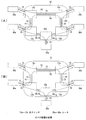
図2を参照して、光伝送網10における光パス配置の移行を行うための光パスの変更について説明する。図2は、光スイッチの切換による光パスの変更を説明するための該略図であって、図2(A)は、移行前の光パス配置を示し、また、図2(B)は、移行後の光パス配置を示している。
With reference to FIG. 2, a description will be given of a change of an optical path for performing an optical path arrangement transition in the
なお、この例では、光伝送網10は、第1〜第5の光スイッチ12a〜12e(以下、符号12で代表することもある。)を備えて構成され、及び、第1〜第5の光スイッチ12a〜12eのそれぞれに第1〜5のルータ30a〜30e(以下、符号30で代表することもある。)が1つずつ対応して接続される構成となっている。光スイッチ12同士の間及び、ルータ30と光スイッチ12の間は、光ファイバ15で接続されている。なお、光伝送網10の構成等はこの例に限定されず、光伝送網10が備える光スイッチ12の個数は、設定に応じた好適な数とすることができる。また、光スイッチ12には、ルータ30は2以上接続されても良いし、ルータ30が接続されない光スイッチ12があっても良い。光パス配置は、各ルータ30におけるパケット送信先の設定と、光スイッチ12の切換とにより設定される。
In this example, the
移行前のパス配置では、第1のルータ30aと第2のルータ30bとの間に、光パスP1が配置され、第2のルータ30bと第3のルータ30cとの間に、光パスP2が配置され、第3のルータ30cと第4のルータ30dとの間に、光パスP3が配置され、第4のルータ30dと第5のルータ30eとの間に光パスP4が配置され、第5のルータ30eと第1のルータ30aとの間に光パスP5が配置されている。さらに、第1のルータ30aと第4のルータ30dとの間に、第1の光スイッチ12a、第2の光スイッチ12b、第3の光スイッチ12c、及び第4の光スイッチ12dを順次に介する光パスP6が配置されている(図2(A))。
In the path arrangement before the transition, the optical path P1 is arranged between the
このような光パス配置に有る場合に(図2(A))、例えば、第3の光スイッチ12cを切り換えると、光パスP2及び光パスP6が解除され、第2のルータ30bと第4のルータ30dとの間に光パスP7を新たに配置し、及び第1のルータ30aと第3のルータ30cとの間に光パスP8を新たに配置することができる(図2(B))。
In the case of such an optical path arrangement (FIG. 2A), for example, when the third
(第1実施形態)
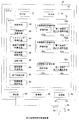
図3及び図4を参照して、第1実施形態の光パス再配置の方法につき説明する。図3は管理装置20の構成を説明するためのブロック図であり、図4は、管理装置20での処理フローを示す図である。尚、以下の説明において、必要に応じて図1及び図2を参照して説明を行う。
(First embodiment)
With reference to FIG. 3 and FIG. 4, the optical path rearrangement method of the first embodiment will be described. FIG. 3 is a block diagram for explaining the configuration of the
管理装置20は、MPU(Microprocessing Unit)60、記憶部66、受信部62、及び送信部64を備えて構成される、周知のコンピュータ等を用いることができる。記憶部66には、ハードディスク等の任意好適な周知の記憶装置が用いられる。MPU60は、周知の構成とすることができ、ここでは、中央処理装置(CPU:Central Processing Unit)70と、メモリとしてのRAM(Random Access Memory)74及びROM(Read Only Memory)72を備える構成としている。
The
CPU70が備える制御手段80は、ROM72等に読み出し自在に記録されているプログラムを読み出して、当該プログラムの実行することにより、CPU70の機能手段として、1段階移行評価手段82、トラフィック監視手段84、最適パス配置計算手段85、保存結果記録手段86、比較手段88、設定信号生成手段90、終了判定手段92、2段階移行評価手段100を実現する。2段階移行評価手段100は、さらに評価手段102及び第1次移行光パス選択手段104を備えている。なお、各機能手段が備える機能については後述する。
The control means 80 provided in the
管理装置20のトラフィック監視手段84は、常時、トラフィック情報を監視していて、ルータ制御回線53及び受信部62を経て、記憶部66又はRAM74等の記憶装置に保存されている現用パス配置での各ルータでのトラフィック情報を受信する。このトラフィック情報は、記憶部66又はRAM74等の記憶装置に読み出し自在に書き込まれる。
The traffic monitoring means 84 of the
最適パス配置計算手段85は、トラフィック情報を記憶部66又はRAM74から読み出して、当該トラフィック情報に基づいて最適パス配置の計算を行い、最適パス配置を得て、これを記憶部66又はRAM74等の記憶装置に格納する。なお、最適パス配置を得るための計算は、任意好適な周知の最適化アルゴリズムを用いることができ、例えば、遺伝的アルゴリズムとすることができる。現用パス配置から、最適パス配置計算手段85により得られた最適パス配置への移行は以下の手順で行われる。
The optimum path arrangement calculation means 85 reads the traffic information from the
尚、最適パス配置の計算は、トラフィック情報の書込みに応答して、現在設定している光パスとは異なる経路のトラフィックが増加した場合などに行われる。また、トラフィック情報を例えば、1日以上の長期間の時間変動情報として保存しておいて、当該時間変動情報に基づいたトラフィック情報としても良い。 The calculation of the optimal path arrangement is performed when traffic on a route different from the currently set optical path increases in response to the writing of traffic information. Further, for example, traffic information may be stored as long-term time fluctuation information for one day or longer and may be traffic information based on the time fluctuation information.
ステップ(以下、ステップをSで表す)1で、1段階移行評価手段82は、1段階移行により光パス配置を変更する際のパケット損失量を評価する1段階移行評価過程を行う。1段階移行評価過程S1は、S10の第1次移行光パスを評価する1段階パケット損失評価過程、及び、S20の評価結果を記録する評価結果記録過程を備えている。この評価結果を、第1評価結果とし、この第1評価結果を第1評価値で与える。 In step (hereinafter, step is represented by S) 1, the one-step transition evaluation means 82 performs a one-step transition evaluation process for evaluating the packet loss amount when changing the optical path arrangement by one-step transition. The one-stage transition evaluation process S1 includes a one-stage packet loss evaluation process that evaluates the first-order transition optical path in S10 and an evaluation result recording process that records the evaluation result in S20. This evaluation result is taken as a first evaluation result, and this first evaluation result is given as a first evaluation value.
図5を参照して1段階移行による光パス再配置について説明する。図5は、1段階移行時の光パス配置を説明するための概略図である。ここでは、光パス再配置を行う光通信ネットワークは、8つのルータ31〜38を備えている例について説明するが、備えるルータの個数は8に限定されるものではない。なお、以下の説明で、光パスを単に、符号Pで表すことがある。
With reference to FIG. 5, the optical path rearrangement by the one-step transition will be described. FIG. 5 is a schematic diagram for explaining an optical path arrangement at the time of shifting to one stage. Here, an example in which an optical communication network that performs optical path rearrangement includes eight
第1評価結果を得るために、先ず、1段階移行評価手段82は、記憶部66又はRAM74等の記憶装置から読み出した現用パス配置(図5(A))と最適パス配置(図5(C))とを比較することにより、パス配置の移行により解除及び設定される光パス群を選択する。ここでは、第1のルータ31と第6のルータ36を結ぶP11、第2のルータ32と第5のルータ35を結ぶP12、第3のルータ33と第8のルータ38を結ぶP13、及び、第4のルータ34と第7のルータ37を結ぶP14が解除される光パス群である。また、第1のルータ31と第5のルータ35を結ぶP21、第2のルータ32と第6のルータ36を結ぶP22、第3のルータ33と第7のルータ37を結ぶP23、及び、第4のルータ34と第8のルータ38を結ぶP24が設定される光パス群である。解除される光パス群を以下、単に解除パスと称し、また、設定される光パス群を以下、単に設定パスと称する。
In order to obtain the first evaluation result, first, the one-step transition evaluation means 82 first reads the current path arrangement (FIG. 5A) read from the
次に、この解除パスの解除(図5(B))によって生じるパケット損失量を、記憶部66又はRAM74から読み出したトラフィック情報に基づいて算出する。ここで、求められたパケット損失量が第1評価結果としての第1評価値である。
Next, the amount of packet loss caused by the cancellation of the cancellation path (FIG. 5B) is calculated based on the traffic information read from the
S20の評価結果記録過程で、保存結果記録手段86により、S10の1段階パケット損失評価過程で得られたパケット損失量、すなわち第1評価値を保存結果として、記憶部66又はRAM74に読み出し及び書換え自在に記録する。
In the evaluation result recording process of S20, the storage result recording means 86 reads out and rewrites the packet loss amount obtained in the one-stage packet loss evaluation process of S10, that is, the first evaluation value, as the storage result to the
この第1評価値を保存結果として記録した後、この記録に応答して2段階移行評価過程S2を行う。2段階移行評価過程S2は、S30の第1次移行光パス選択過程、及び、S40の2段階パケット損失評価過程を備えている。 After this first evaluation value is recorded as a storage result, a two-stage transition evaluation process S2 is performed in response to this recording. The two-stage transition evaluation process S2 includes a first-order transition optical path selection process in S30 and a two-stage packet loss evaluation process in S40.
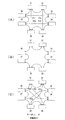
図6を参照して2段階移行による光パス再配置について説明する。図6は、2段階移行時の光パス配置を説明するための概略図である。図6(A)は、図5(A)と同様に現用パス配置を示している。 The optical path rearrangement by the two-stage transition will be described with reference to FIG. FIG. 6 is a schematic diagram for explaining the optical path arrangement at the time of the two-stage transition. FIG. 6A shows the working path arrangement in the same manner as FIG.
S30の第1次移行光パス選択過程で、2段階移行評価手段100の第1次移行光パス選択手段104は、解除パスを2つのグループに分け、一方のグループに属する光パスを第1次移行光パスとして選択し、他方のグループに属する光パスを第2次移行光パスとする。ここでは、解除パスの半数を第1次移行光パスとして選択し、残りの半数を第2次移行光パスとするものとして説明する。なお、この第1次移行光パスの選択は、解除パスであるP11、P12、P13及びP14から、無作為に半数を選ぶ。この例では、第1次移行光パスとしてP11及びP12を選択し、残りのP13及びP14を第2次移行光パスとする。 In the first-order transition optical path selection process of S30, the first-order transition optical path selection means 104 of the two-stage transition evaluation means 100 divides the release paths into two groups and sets the optical paths belonging to one group to the first order. The optical path belonging to the other group is selected as the transition optical path, and the second transition optical path is selected. Here, description will be made assuming that half of the cancellation paths are selected as the first-order transfer light paths and the remaining half are the second-order transfer light paths. In this selection of the first-order transition optical path, half of the paths are randomly selected from P11, P12, P13, and P14 that are cancellation paths. In this example, P11 and P12 are selected as the primary transfer light paths, and the remaining P13 and P14 are set as the secondary transfer light paths.
S40の2段階パケット損失評価過程では、2段階移行評価手段100の評価手段102は、S30で選択された第1次移行光パス及び第2次移行光パス、及び、記憶部66又はRAM74から読み出したトラフィック情報に基づいて、2段階移行により光パス配置を移行する際のパケット損失量を計算する。この計算の結果求められたパケット損失量は、第2評価結果としての第2評価値であり、RAM74に読み出し自在に記録される。
In the two-stage packet loss evaluation process at S40, the evaluation means 102 of the two-stage transition evaluation means 100 reads from the first and second transition optical paths selected at S30 and the
2段階移行では、先ず、第1次移行パスであるP11及びP12が解除される(図6(B))。次に、解除により使用可能となる、ルータ及び光スイッチの入出力ポートなどのネットワーク資源を利用して、設定パスであるP21及びP22が設定される(図6(C))。次に、第2次移行パスであるP13及びP14が解除される(図6(D))。次に、P13及びP14の解除により使用可能となるネットワーク資源を利用して、P23及びP24が設定され、その結果として最適パス配置が得られる(図6(E))。図6(B)及び図6(D)に示した光パスの一部が解除された状態のトラフィック損失量の和がパケット損失量である。 In the two-stage transition, first, the primary transition paths P11 and P12 are released (FIG. 6B). Next, P21 and P22 which are setting paths are set by using network resources such as routers and optical switch input / output ports which can be used by the release (FIG. 6C). Next, P13 and P14, which are secondary migration paths, are released (FIG. 6D). Next, P23 and P24 are set by using network resources that can be used by releasing P13 and P14, and as a result, an optimal path arrangement is obtained (FIG. 6E). The sum of the traffic loss amounts when a part of the optical paths shown in FIGS. 6B and 6D is released is the packet loss amount.
第2評価結果のRAM74への書込みに応答して、比較過程S3が始動する。比較過程S3は、S50とS60とを含む。S50では、比較手段88は、RAM74に記録されている第2評価結果すなわち第2評価値と、RAM74又は記憶部66に記録されている第1評価値とをそれぞれ読み出して、第2評価値と第1評価値とを比較して評価を行う。比較の結果、第2評価値が第1評価値よりも小さい場合には、評価結果が保存結果よりも優れている、すなわち、評価結果のパケット損失量が、保存結果のパケット損失量よりも少ないと判定する。第2評価値が優れていると判定された場合には、その判定に応答して、S60において、第2評価値を旧保存結果、すなわち、第1評価値の代わりに置き換えて、新たに保存結果としてRAM74又は記憶部66に記録する。
In response to the writing of the second evaluation result to the
S70では、保存結果の書換えの終了に応答して、終了判定手段92は、処理終了条件を満たすか否か判定する。この処理終了条件は、例えば、管理装置20での処理を行う時間としたり、或いは、2段階移行過程S2、及び比較過程S3の一巡過程を繰り返し実施する実施回数としたりする等、任意好適に設定可能である。処理の一巡毎に、記憶装置から読み出された処理終了条件と比較して、この処理終了条件は、予めROM72等に読み出し自在に記録されている。この処理終了条件を満たすまで、2段階移行評価過程、及び比較過程が繰り返し行われる。
In S70, in response to the end of rewriting the storage result, the
第1実施形態の光通信ネットワークにおける光パス配置移行方法によれば、1段階移行により光パス配置を変更する場合と、2段階移行により光パス配置を変更する場合について、処理終了条件の範囲内で、最もパケットの損失量の少ない最適解を発見することが可能となる。 According to the optical path arrangement transition method in the optical communication network of the first embodiment, the case where the optical path arrangement is changed by the one-stage transition and the case where the optical path arrangement is changed by the two-stage transition is within the range of the processing end condition. Thus, it is possible to find an optimal solution with the least amount of packet loss.
最適解を発見した後、この最適解に従って、ルータ及び光スイッチの切換を行うことにより、現用パス配置から最適パス配置への移行、すなわち、光パス再配置が、パケット損失量の最も少ない状態で行われる。 After finding the optimal solution, switching between the router and the optical switch is performed according to the optimal solution, so that the transition from the working path allocation to the optimal path allocation, that is, the optical path relocation is performed with the least amount of packet loss. Done.
(第2実施形態)
図7及び図8を参照して、第2実施形態の光パス移行方法につき説明する。図7は管理装置20の構成を説明するためのブロック図であり、図8は、管理装置20での処理フローを示す図である。光パス再配置を行う光通信ネットワークについては、図1及び図2を参照して説明したので、ここでは説明を省略する。図3及び図4を参照して説明した、第1実施形態の光パス再配置と重複する説明も省略する。
(Second Embodiment)
With reference to FIGS. 7 and 8, the optical path shifting method of the second embodiment will be described. FIG. 7 is a block diagram for explaining the configuration of the
管理装置20は、評価結果集計手段94と複数の2段階移行評価手段100a〜100cを備えている。なお、この複数の2段階移行評価手段100a〜100cは、必ずしも管理装置20の内部に備える構成ではなくてもよく、管理装置20の外部に別途設ける構成としても良い。
The
S10及びS20は、第1実施形態と同じなので説明を省略する。 Since S10 and S20 are the same as in the first embodiment, description thereof is omitted.
S30の第1次移行光パス選択過程で、2段階移行評価手段100a〜100cの第1次移行光パス選択手段104a〜104cは、2段階移行により光パス配置を変更する際の第1次移行光パスを複数選択する。 In the first-order transition optical path selection process of S30, the first-order transition optical path selection means 104a to 104c of the two-stage transition evaluation means 100a to 100c perform the first-order transition when the optical path arrangement is changed by the two-stage transition. Select multiple optical paths.
S40の2段階パケット損失評価過程では、2段階移行評価手段100a〜100cの評価手段102a〜102cは、S30で選択された第1次移行光パス及び第2次移行光パス、及び、記憶部66又はRAM74から読み出したトラフィック情報に基づいて、2段階移行により光パス配置を移行する際のパケット損失量を計算する。なお、第2実施形態では、S30の第1次移行光パス選択過程及びS40の2段階パケット損失評価過程は、管理装置20が備える2段階移行評価手段100a〜100cと同じ数だけ同時に実施する。
In the two-stage packet loss evaluation process in S40, the evaluation means 102a to 102c of the two-stage transition evaluation means 100a to 100c are the first and second transition optical paths selected in S30, and the
S45では、評価結果集計手段94は、同時に実施されたS40の2段階パケット損失評価過程で得られたパケット損失量の中で最も小さいものを、第2評価値としてRAM74に読み出し自在に記録する。
In S45, the evaluation result totaling means 94 records the smallest packet loss amount obtained in the two-stage packet loss evaluation process of S40 performed at the same time as a second evaluation value in a freely readable manner in the
S50以降については、第1実施形態と同様なので説明を省略する。 Since S50 and subsequent steps are the same as those in the first embodiment, description thereof will be omitted.
第2実施形態のパス配置移行方法によれば、2段階移行評価過程を同時に複数行い、その結果のなかで最も優れたものを評価結果とするので、第1実施形態で得られる効果に加えて、さらに短時間で最適解を発見することができる。 According to the path placement transition method of the second embodiment, a plurality of two-stage transition evaluation processes are performed simultaneously, and the most excellent result is used as the evaluation result. In addition to the effects obtained in the first embodiment, In addition, the optimal solution can be found in a shorter time.
(第3実施形態)
図9及び図10を参照して、第3実施形態の光パス移行方法につき説明する。図9は管理装置20の構成を説明するためのブロック図であり、図10は、管理装置20での処理フローを示す図である。光パス再配置を行う光通信ネットワークについては、図1及び図2を参照して説明したので、ここでは説明を省略する。図3及び図4を参照して説明した、第1実施形態の光パス移行と重複する説明も省略する。
(Third embodiment)
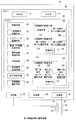
With reference to FIGS. 9 and 10, an optical path shifting method of the third embodiment will be described. FIG. 9 is a block diagram for explaining the configuration of the
管理装置20は、評価結果集計手段94と2〜N段階移行評価手段(Nは2以上の整数)100、110及び120を備えている。3段階移行評価手段110が備える第1次移行用パス選択手段114は、3段階移行により光パス配置を変更する際の第1次移行光パスを選択する。ここでは、解除パスの3分の1を第1次移行光パスとして選択する。3段階移行評価手段110が備える第2次移行用パス選択手段116は、第1次移行光パスとして選択されなかった解除パスの半数を第2次移行用パス選択手段として選択する。残りの半数が第3次移行光パスである。なお、この第1次移行光パス及び第2次移行光パスの選択は、解除パスから、無作為に選ばれる。同様に、N段階移行評価手段120は、第1〜N−1次移行光パス選択手段124、126及び128を備えていて、第1〜第N次移行光パスに分類する。
The
S10及びS20は、第1実施形態と同じなので説明を省略する。 Since S10 and S20 are the same as in the first embodiment, description thereof is omitted.
S30の第1次移行光パス選択過程では、2段階移行評価手段100の第1次移行光パス選択手段104は、2段階移行により光パス配置を変更する際の第1次移行光パスを選択する。 In the first-order transition optical path selection process at S30, the first-order transition optical path selection means 104 of the two-stage transition evaluation means 100 selects the first-order transition optical path when changing the optical path arrangement by the two-stage transition. To do.
S40の2段階パケット損失評価過程では、2段階移行評価手段100の評価手段102は、S30で選択された第1次移行光パス及び第2次移行光パス、及び、記憶部66又はRAM74から読み出したトラフィック情報に基づいて、2段階移行により光パス配置を移行する際のパケット損失量を計算する。
In the two-stage packet loss evaluation process at S40, the evaluation means 102 of the two-stage transition evaluation means 100 reads from the first and second transition optical paths selected at S30 and the
S30及びS40の一連の過程と同時に、S31の第1次移行光パス選択過程で、3段階移行評価手段110の第1次移行光パス選択手段114は、解除パスを3つのグループに分け、1つのグループに属する光パスを第1次移行光パスとして選択する。ここでは、解除パスを3等分して3つのグループに分けるものとする。次に、S33で、3段階移行評価手段110が備える第2次移行パス選択手段116は、解除パスを分類した3つのグループの中で、第1次移行光パスとして選択されなかった2つのグループの一方を第2次移行用パスとして選択する。第1次移行光パス及び第2次移行光パスとして選択されなかったグループに属する光パスが第3次移行光パスである。なお、この第1次及び第2次移行光パスの選択は、解除パスから、無作為に選ぶことで行われる。
Simultaneously with the series of steps S30 and S40, in the first-order transition optical path selection step S31, the first-order transition optical path selection means 114 of the three-stage transition evaluation means 110 divides the release paths into three groups, 1 The optical paths belonging to one group are selected as the primary transition optical paths. Here, it is assumed that the release path is equally divided into three groups. Next, in S33, the second transition
S42の3段階パケット損失評価過程では、S31及びS33で選択された第1〜3次移行光パスに基づく、3段階移行により光パス配置を移行する際のパケット損失量を計算する。 In the three-stage packet loss evaluation process of S42, the amount of packet loss when shifting the optical path arrangement by the three-stage transition based on the first to third order transition optical paths selected in S31 and S33 is calculated.
S30及びS40の一連の過程と同時に、さらに、S32、S34、及びS36の第1〜N−1次移行光パス選択過程によりN段階移行手段は、解除パスを第1〜第N次移行光パスに分類する。 Simultaneously with the series of steps S30 and S40, the N-stage transition means uses the first to N-1 order transition optical path selection processes of S32, S34, and S36 to change the release path to the first to Nth order transition optical paths. Classify into:
S44のN段階パケット損失評価過程では、S32、S34及びS36で分類された第1〜N次移行光パスに基づく、N段階移行により光パス配置を移行する際のパケット損失量を計算する。 In the N-stage packet loss evaluation process of S44, the packet loss amount when the optical path arrangement is shifted by the N-stage transition based on the first to N-th order transition optical paths classified in S32, S34, and S36 is calculated.
S45の多段階移行評価過程では、評価結果集計手段は、同時に実施されたS40、S42及びS44の2〜N段階パケット損失評価過程で得られたパケット損失量の中で最も小さいものを、評価結果である第2評価値としてRAM74に読み出し自在に記録する。
In the multi-stage transition evaluation process of S45, the evaluation result totaling means calculates the smallest packet loss amount obtained in the 2-N stage packet loss evaluation process of S40, S42 and S44 performed simultaneously. The second evaluation value is recorded in the
S50以降については、第1実施形態と同様なので説明を省略する。 Since S50 and subsequent steps are the same as those in the first embodiment, description thereof will be omitted.
第3実施形態のパス配置移行方法によれば、2〜N段階移行評価過程を同時に複数行い、その結果のなかで最も優れたものを評価結果とするので、第1実施形態で得られる効果に加えて、移行の段階数を増やすことで、よりパケット損失量が少ない移行手順を見つけることができる。 According to the path placement transition method of the third embodiment, a plurality of 2 to N stage transition evaluation processes are performed simultaneously, and the most excellent result is used as the evaluation result. In addition, it is possible to find a transition procedure with a smaller amount of packet loss by increasing the number of stages of transition.
(第4実施形態)
図11及び図12を参照して、第4実施形態の光パス移行方法につき説明する。図11は管理装置20の構成を説明するためのブロック図であり、図12は、管理装置20での処理フローを示す図である。光パス再配置を行う光通信ネットワークについては、図1及び図2を参照して説明したので、ここでは説明を省略する。図7及び図8を参照して説明した、第2実施形態の光パス移行と重複する説明も省略する。
(Fourth embodiment)
With reference to FIGS. 11 and 12, an optical path shifting method of the fourth embodiment will be described. FIG. 11 is a block diagram for explaining the configuration of the
管理装置20は、近傍解検索手段96及び局所最適脱出手段98を備えている。
The
S10からS40までの過程は、第2実施形態と同じ過程なので説明を省略する。 Since the processes from S10 to S40 are the same as those in the second embodiment, the description thereof is omitted.
S43では、評価結果集計手段94は、同時に実施されたS40の2段階パケット損失評価過程で得られたパケット損失量の中で最も小さいものの、パケット損失量と、第1次及び第2次移行光パスを、最適解としてRAM74に読み出し自在に記録する。
In S43, the evaluation result totaling means 94, although the smallest packet loss amount obtained in the two-stage packet loss evaluation process of S40 performed at the same time, the packet loss amount and the primary and secondary transition lights. The path is recorded as an optimum solution in the
S46で、近傍解検索手段96は、RAM74から読み出した最適解から複数の、好適には、CPU70が備える2段階移行評価手段の数以上の近傍解を検索し、その結果をRAM74又は記憶部66に読み出し自在に記録する。ここで、近傍解とは、最適解の第1次移行光パス(以下、単に最適第1次移行光パスと称する。)で変更される光パスの半数未満を最適解の第2次移行光パス(以下、単に最適第2次移行光パスと称する。)で置き換えたものをいう。好適には、最適第1次移行光パスから無作為に選択した1つの光パスを、最適第2次移行光パスから無作為に選択した1つの光パスと置き換えたものを近傍解とするのが良い。
In S46, the neighborhood solution search means 96 searches the plurality of optimum solutions read from the
2段階移行評価手段100a〜100cの第1次移行光パス選択手段104a〜104cは、2段階移行により光パス配置を変更する際の第1次移行光パスを選択する第1次移行光パス選択過程を行う。なお、この第1次移行光パスの選択は、RAM74又は記憶部66に記録されている近傍解から無作為に選択する。
The first-order transition light path selection means 104a to 104c of the two-stage transition evaluation means 100a to 100c select the first-order transition light path selection for selecting the first-order transition light path when changing the optical path arrangement by the two-stage transition. Do the process. The selection of the first-order transition light path is randomly selected from the neighborhood solutions recorded in the
S48では、S46で選択された第1次移行光パス及び第2次移行光パスに基づく、2段階移行により光パス配置を変更する際のパケット損失量を計算して評価する2段階パケット損失評価過程を行う。なお、第4実施形態では、S46の第1次移行光パス選択過程及びS48の2段階パケット損失評価過程を2段階移行評価手段と同じ数だけ同時に実施する。 In S48, a two-stage packet loss evaluation for calculating and evaluating a packet loss amount when changing the optical path arrangement by the two-stage transition based on the first-order transition optical path and the second-order transition optical path selected in S46. Do the process. In the fourth embodiment, the same number of steps of the first-order transition optical path selection process of S46 and the two-stage packet loss evaluation process of S48 are performed at the same time as the two-stage transition evaluation means.
S49では、評価結果集計手段94は、同時に実施されたS40の2段階パケット損失評価過程で得られたパケット損失量の中で最も小さいものの、パケット損失量と、第1次及び第2次移行光パスを、最適解としてRAM74に読み出し自在に記録する。
In S49, the evaluation result totaling means 94, although the packet loss amount obtained in the two-stage packet loss evaluation process of S40 performed simultaneously is the smallest, the packet loss amount and the primary and secondary transition lights. The path is recorded as an optimum solution in the
S50では、比較手段88は、RAM74に記録されている最適解のトラフィック量と、RAM74又は記憶部66に記録されている第1評価値が示すトラフィック量とをそれぞれ読み出して、比較して評価を行う。比較の結果、最適解のパケット損失量が、第1評価値が示すトラフィック量よりも小さい場合には、評価結果が保存結果よりも優れている、すなわち、評価結果のパケット損失量が、保存結果のパケット損失量よりも少ないと判定する。最適解が優れていると判定された場合には、その判定に応答して、S60において、最適解を旧保存結果、すなわち、第1評価値の代わりに置き換えて、新たに保存結果としてRAM74又は記憶部66に記録する。
In S50, the comparison means 88 reads out the traffic volume of the optimal solution recorded in the
S70では、保存結果の書換えの終了に応答して、終了判定手段92は、処理終了条件を満たすか否か判定する。この処理終了条件は、例えば、管理装置20での処理を行う時間としたり、或いは、2段階移行過程S2、及び比較過程S3の一巡過程を繰り返し実施する実施回数としたりする等、任意好適に設定可能である。処理の一巡毎に、記憶装置から読み出された処理終了条件と比較して、この処理終了条件は、予めROM72等に読み出し自在に記録されている。この処理終了条件を満たすまで、S46〜S60の過程が繰り返し行われる。
In S70, in response to the end of rewriting the storage result, the
なお、S46の第1次移行光パス選択過程では、第1次移行光パス選択手段104a〜104cは、第1次移行光パスから近傍解を選択するだけでなく、局所最適脱出解を選択することができる。ここで、局所最適脱出解とは、局所最適脱出手段98がRAM74から読み出した最適解に基づいて最適解での第1次移行光パスの半数以上を第2次移行光パスで置き換えたものであって、RAM74又は記憶部66等に読み出し自在に記録されている。なお、最適解での第1次移行光パスを全て第2次移行光パスで置き換えても良い。
In the first-order transition light path selection process of S46, the first-order transition light path selection means 104a to 104c not only select a neighborhood solution from the first-order transition light path, but also select a local optimal escape solution. be able to. Here, the local optimum escape solution is obtained by replacing more than half of the first-order transition light paths in the optimum solution with the second-order transition light paths based on the optimum solution read out from the
局所最適脱出解は、S46〜S60の繰り返し毎に1つ選択しても良いし、S46〜S60の処理を複数回繰り返した後に、局所最適脱出解を1つ選択しても良い。 One local optimal escape solution may be selected for each iteration of S46 to S60, or one local optimal escape solution may be selected after the processing of S46 to S60 is repeated a plurality of times.
第4実施形態のパスの配置方法によれば、2段階移行評価過程を行うにあたり、保存結果を得たパスの近傍解を用いることで、最適解の検索時間を短縮することができる。また、保存結果を得たパスとは異なる局所最適脱出解を用いて2段階移行評価過程を行うことで、局所最適に陥ることなく、最適解の検索を行うことができる。 According to the path arrangement method of the fourth embodiment, in performing the two-stage transition evaluation process, the search time for the optimum solution can be shortened by using the neighborhood solution of the path obtained as the storage result. Further, by performing the two-stage transition evaluation process using a local optimal escape solution different from the path from which the stored result is obtained, the optimal solution can be searched without falling into the local optimal.
また、上記各実施形態は、パス配置変更時のパケット損失量の合計を最小化することを目的とした構成となっている。しかし、パス配置を変更する際の変更方法を選択する評価指標として、予想されるパケット損失量以外の評価指標を用いることも考えられる。 Each of the above embodiments is configured to minimize the total amount of packet loss when the path arrangement is changed. However, it is also conceivable to use an evaluation index other than the expected packet loss amount as an evaluation index for selecting a change method when changing the path arrangement.
この別の評価指標としては、例えば、移行時におけるパケットの転送遅延時間の予想最悪値を用い、これを最小にする変更方法を選択する構成としても良い。また、移行時に最も負荷のかかるルータのトラフィック量を用い、これを最小にする変更方法を選択する構成としても良い。これらの場合、上記各実施形態で説明した処理手順を変更する必要はなく、各段階で計算する際の評価値を、各評価指標に対応するものに変更すれば良い。 As another evaluation index, for example, an expected worst value of the packet transfer delay time at the time of transition may be used, and a change method that minimizes this may be selected. Alternatively, a configuration may be adopted in which the traffic amount of the router that is most loaded at the time of migration is used, and a change method that minimizes this is selected. In these cases, it is not necessary to change the processing procedure described in each of the above embodiments, and the evaluation value at the time of calculation may be changed to one corresponding to each evaluation index.
10 光伝送網
12a、12b、12c、12d、12e 光スイッチ
15 光ファイバ
20 管理装置
30、30a、30b、30c、30d、30e ルータ
31、32、33、34、35、36、37、38 ルータ
40 外部ネットワーク
50 制御回線
51 光スイッチ制御回線
52 光スイッチ設定信号
53 ルータ制御回線
54 ルータ設定信号
55 トラフィックモニタ信号
60 MPU
62 受信部
64 送信部
66 記憶部
70 CPU
72 ROM
74 RAM
80 制御手段
82 1段階以降評価手段
84 トラフィック監視手段
85 最適パス配置計算手段
86 保存結果記録手段
88 比較手段
90 設定信号生成手段
92 終了判定手段
94 評価結果集計手段
96 近傍解検索手段
98 局所最適脱出手段
100、100a、100b、100c 2段階移行評価手段
102、102a、102b、102c、112、122 評価手段
104、104a、104b、104c、114、124 第1次移行パス選択手段
110 3段階移行評価手段
116、126 第2次移行パス選択手段
120 N段階移行評価手段
128 第N−1次移行パス選択手段
DESCRIPTION OF
62 receiving
72 ROM
74 RAM
80 Control means 82 Evaluation means after one
Claims (4)
1段階移行により光パス配置を変更する際のパケット損失量を評価して第1評価値を求める1段階パケット損失評価過程と、
前記第1評価値を記憶装置に記録する第1評価値記録過程と、
第1次移行及び第2次移行の2段階移行により光パス配置を変更する際に、変更する光パス群を二分した一方の光パス群を第1次移行光パスとして選択し、他方の光パス群を第2次移行光パスとする第1次移行光パス選択過程、及び、2段階移行により光パス配置を変更する際のパケット損失量を評価して第2評価値を求める2段階パケット損失評価過程を含む2段階移行評価過程と、
該第2評価値を前記第1評価値と比較して、該第2評価値が前記第1評価値よりも小さい場合には、第1評価値を該第2評価値で置き換えた後、該第1評価値と、前記第1 次及び第2次移行光パスとを前記記憶装置に記録する比較過程と
を備え、
予め記憶装置に記録されている処理終了条件を読み出してきて、該処理終了条件を満たすまで、前記2段階移行評価過程、及び前記比較過程を繰り返し行う
ことを特徴とする光通信ネットワークにおける光パス再配置方法。 In relocating an optical path in an optical communication network including a plurality of routers, a plurality of optical switches, an optical fiber connecting between the router and the optical switches or between the optical switches, and a management device,
A one-stage packet loss evaluation process for evaluating a packet loss amount when changing the optical path arrangement by one-stage transition to obtain a first evaluation value;
A first evaluation value recording process for recording the first evaluation value in a storage device;
When the optical path arrangement is changed by the two-stage transition of the primary transition and the secondary transition, one optical path group that bisects the optical path group to be changed is selected as the primary transition optical path, and the other light A first-stage optical path selection process in which a path group is a second-order optical path, and a two-stage packet for obtaining a second evaluation value by evaluating a packet loss amount when changing the optical path arrangement by two-stage transition A two-stage transition assessment process including a loss assessment process;
When the second evaluation value is compared with the first evaluation value, and the second evaluation value is smaller than the first evaluation value, the first evaluation value is replaced with the second evaluation value, A comparison process of recording a first evaluation value and the primary and secondary transition light paths in the storage device;
A process end condition recorded in advance in a storage device is read, and the two-stage transition evaluation process and the comparison process are repeated until the process end condition is satisfied. Placement method.
ことを特徴とする請求項1に記載の光通信ネットワークにおける光パス再配置方法。 In the first-order transition optical path selection process, a plurality of first-order transition paths and second-order transition path sets are simultaneously selected, and in the two-stage packet loss evaluation process, a plurality of first-order paths selected A packet loss amount relating to each of a migration path and a secondary migration path group is simultaneously obtained, and the smallest packet loss amount among the obtained plurality of packet loss amounts is set as a second evaluation value. The optical path rearrangement method in the optical communication network according to claim 1.
1段階移行により光パス配置を変更する際のパケット損失量を評価して第1評価値を求める1段階パケット損失評価過程と、
前記第1評価値を記憶装置に記録する第1評価値記録過程と、
第1〜N次移行(但し、Nは2以上の整数)のN段階移行により光パス配置を変更する際に、変更する光パス群をN等分して第1〜N−1次移行光パスをそれぞれ選択し、残りを第N次移行光パスとする第1〜N−1次移行光パス選択過程、及び、N段階移行により光パス配置を変更する際のパケット損失量を求めるN段階移行評価過程とを備え、
第2〜N段階移行評価過程をそれぞれ行って、求められた複数のパケット損失量の中で最も小さいパケット損失量を第2評価値とする多段階移行評価過程、及び
該第2評価値を前記第1評価値と比較して、該第2評価値が前記第1評価値よりも小さい場合には、第1評価値を該第2評価値で置き換えた後、該第1評価値と、前記第1 〜N次移行光パスとを前記記憶装置に記録する比較過程
をさらに備え、
予め記憶装置に記録されている処理終了条件を読み出してきて、該処理終了条件を満たすまで、前記2〜N段階移行評価過程、多段階移行評価過程及び前記比較過程を繰り返し行う
ことを特徴とする光通信ネットワークにおける光パス再配置方法。 In relocating an optical path in an optical communication network including a plurality of routers, a plurality of optical switches, an optical fiber connecting between the router and the optical switches or between the optical switches, and a management device,
A one-stage packet loss evaluation process for evaluating a packet loss amount when changing the optical path arrangement by one-stage transition to obtain a first evaluation value;
A first evaluation value recording process for recording the first evaluation value in a storage device;
When the optical path arrangement is changed by N-stage transition of the first to Nth order transitions (where N is an integer of 2 or more), the first to Nth order transition lights are divided into N equal parts. Each of the paths is selected, and the first to (N-1) th order transition optical path selection process using the remaining as the Nth order transition optical path, and the N stage for obtaining the packet loss amount when changing the optical path arrangement by the N stage transition. A transition assessment process,
A multi-stage transition evaluation process in which the second to N-stage transition evaluation processes are performed and the smallest packet loss amount among the obtained plurality of packet loss amounts is set as a second evaluation value, and the second evaluation value is When the second evaluation value is smaller than the first evaluation value as compared with the first evaluation value, the first evaluation value is replaced with the second evaluation value, and then the first evaluation value and the A comparison process of recording the first to Nth order transition optical paths in the storage device;
The process end condition recorded in the storage device is read in advance, and the 2-N stage transition evaluation process, the multi-stage transition evaluation process, and the comparison process are repeated until the process end condition is satisfied. An optical path relocation method in an optical communication network.
Priority Applications (2)
| Application Number | Priority Date | Filing Date | Title |
|---|---|---|---|
| JP2004358076A JP3983245B2 (en) | 2004-12-10 | 2004-12-10 | Optical path relocation method in optical communication network and management apparatus used in optical communication network |
| US11/296,697 US7493041B2 (en) | 2004-12-10 | 2005-12-08 | Optical path re-arrangement method for optical communication network |
Applications Claiming Priority (1)
| Application Number | Priority Date | Filing Date | Title |
|---|---|---|---|
| JP2004358076A JP3983245B2 (en) | 2004-12-10 | 2004-12-10 | Optical path relocation method in optical communication network and management apparatus used in optical communication network |
Publications (2)
| Publication Number | Publication Date |
|---|---|
| JP2006166316A true JP2006166316A (en) | 2006-06-22 |
| JP3983245B2 JP3983245B2 (en) | 2007-09-26 |
Family
ID=36667774
Family Applications (1)
| Application Number | Title | Priority Date | Filing Date |
|---|---|---|---|
| JP2004358076A Expired - Fee Related JP3983245B2 (en) | 2004-12-10 | 2004-12-10 | Optical path relocation method in optical communication network and management apparatus used in optical communication network |
Country Status (2)
| Country | Link |
|---|---|
| US (1) | US7493041B2 (en) |
| JP (1) | JP3983245B2 (en) |
Cited By (2)
| Publication number | Priority date | Publication date | Assignee | Title |
|---|---|---|---|---|
| JP2010141704A (en) * | 2008-12-12 | 2010-06-24 | Mitsubishi Electric Corp | Optical path rearrangement method and optical communication network system |
| JP2011199455A (en) * | 2010-03-18 | 2011-10-06 | Fujitsu Ltd | Apparatus, method and program for designing of optical network |
Family Cites Families (6)
| Publication number | Priority date | Publication date | Assignee | Title |
|---|---|---|---|---|
| JPH0749790A (en) * | 1993-06-01 | 1995-02-21 | Matsushita Electric Ind Co Ltd | Interrupt control method and interrupt control circuit in processor |
| KR100301950B1 (en) * | 1999-04-02 | 2001-10-29 | 윤덕용 | Apparatus for monitoring optical path based on the identification of optical cross-connect input ports |
| US6317439B1 (en) * | 1999-06-03 | 2001-11-13 | Fujitsu Network Communications, Inc. | Architecture for a SONET line unit including optical transceiver, cross-connect and synchronization subsystem |
| JP4328478B2 (en) * | 2001-08-27 | 2009-09-09 | 富士通株式会社 | Route changing method, label switching node and management node in label transfer network |
| CA2419477C (en) * | 2002-02-28 | 2010-05-04 | Nippon Telegraph And Telephone Corporation | Node used in photonic network, and photonic network |
| US6940863B2 (en) * | 2003-01-13 | 2005-09-06 | The Regents Of The University Of California | Edge router for optical label switched network |
-
2004
- 2004-12-10 JP JP2004358076A patent/JP3983245B2/en not_active Expired - Fee Related
-
2005
- 2005-12-08 US US11/296,697 patent/US7493041B2/en not_active Expired - Fee Related
Cited By (2)
| Publication number | Priority date | Publication date | Assignee | Title |
|---|---|---|---|---|
| JP2010141704A (en) * | 2008-12-12 | 2010-06-24 | Mitsubishi Electric Corp | Optical path rearrangement method and optical communication network system |
| JP2011199455A (en) * | 2010-03-18 | 2011-10-06 | Fujitsu Ltd | Apparatus, method and program for designing of optical network |
Also Published As
| Publication number | Publication date |
|---|---|
| US7493041B2 (en) | 2009-02-17 |
| JP3983245B2 (en) | 2007-09-26 |
| US20060159453A1 (en) | 2006-07-20 |
Similar Documents
| Publication | Publication Date | Title |
|---|---|---|
| US11082290B2 (en) | Method and apparatus for optimizing a software defined network configuration | |
| US8862775B2 (en) | Network server and load balancing routing method for networks thereof | |
| Zhang et al. | Shared fiber delay line buffers in asynchronous optical packet switches | |
| US8327021B2 (en) | Technique of determining connectivity solutions for network elements | |
| Caria et al. | A performance study of network migration to SDN-enabled traffic engineering | |
| US7395351B1 (en) | Method for assigning link weights in a communications network | |
| US10367654B2 (en) | Network design method for ethernet ring protection switching | |
| US20070172237A1 (en) | Methods and apparatus for optimizing utilization in reconfigurable optical add-drop multiplexer based ring network | |
| US9071384B2 (en) | Network design apparatus, network design method, and storage medium storing network design program | |
| EP3622693A1 (en) | Method, computer readable storage medium and device for packet transmission in convergecast network | |
| CN117978738A (en) | Message transmission method and device, storage medium and electronic device | |
| JP3983245B2 (en) | Optical path relocation method in optical communication network and management apparatus used in optical communication network | |
| Wu et al. | Comparison of OXC node architectures for WDM and flex-grid optical networks | |
| US20120140635A1 (en) | Data relay device and route selection method | |
| Chang et al. | Using switched delay lines for exact emulation of FIFO multiplexers with variable length bursts | |
| CN116055405B (en) | Method, device, electronic equipment and storage medium for realizing dynamic ECMP load rebalancing | |
| JPH02277354A (en) | Adaptive type route selection control method | |
| Ravikumar et al. | Kautz graphs as attractive logical topologies in multihop lightwave networks | |
| US20080159138A1 (en) | Methods and devices for providing ingress routing in selective randomized load balancing | |
| Pan et al. | Add/drop flexibility and system complexity tradeoff in ROADM designs | |
| JP3801951B2 (en) | Route selection method | |
| CN102325070A (en) | Service grooming method and device | |
| US6188696B1 (en) | Method of operating a communication network to provide load balancing | |
| Lastine | Efficient communication using multiple cycles and multiple channels | |
| CN121309447B (en) | Distributed online self-adaptive routing method and device oriented to dragonfly topology |
Legal Events
| Date | Code | Title | Description |
|---|---|---|---|
| A131 | Notification of reasons for refusal |
Free format text: JAPANESE INTERMEDIATE CODE: A131 Effective date: 20070109 |
|
| A521 | Written amendment |
Free format text: JAPANESE INTERMEDIATE CODE: A523 Effective date: 20070312 |
|
| A02 | Decision of refusal |
Free format text: JAPANESE INTERMEDIATE CODE: A02 Effective date: 20070403 |
|
| A521 | Written amendment |
Free format text: JAPANESE INTERMEDIATE CODE: A523 Effective date: 20070604 |
|
| A911 | Transfer to examiner for re-examination before appeal (zenchi) |
Free format text: JAPANESE INTERMEDIATE CODE: A911 Effective date: 20070612 |
|
| TRDD | Decision of grant or rejection written | ||
| A01 | Written decision to grant a patent or to grant a registration (utility model) |
Free format text: JAPANESE INTERMEDIATE CODE: A01 Effective date: 20070703 |
|
| A61 | First payment of annual fees (during grant procedure) |
Free format text: JAPANESE INTERMEDIATE CODE: A61 Effective date: 20070703 |
|
| FPAY | Renewal fee payment (event date is renewal date of database) |
Free format text: PAYMENT UNTIL: 20100713 Year of fee payment: 3 |
|
| R150 | Certificate of patent or registration of utility model |
Free format text: JAPANESE INTERMEDIATE CODE: R150 |
|
| FPAY | Renewal fee payment (event date is renewal date of database) |
Free format text: PAYMENT UNTIL: 20110713 Year of fee payment: 4 |
|
| FPAY | Renewal fee payment (event date is renewal date of database) |
Free format text: PAYMENT UNTIL: 20120713 Year of fee payment: 5 |
|
| FPAY | Renewal fee payment (event date is renewal date of database) |
Free format text: PAYMENT UNTIL: 20130713 Year of fee payment: 6 |
|
| LAPS | Cancellation because of no payment of annual fees |