JP2006165807A - Image formation system - Google Patents
Image formation system Download PDFInfo
- Publication number
- JP2006165807A JP2006165807A JP2004351665A JP2004351665A JP2006165807A JP 2006165807 A JP2006165807 A JP 2006165807A JP 2004351665 A JP2004351665 A JP 2004351665A JP 2004351665 A JP2004351665 A JP 2004351665A JP 2006165807 A JP2006165807 A JP 2006165807A
- Authority
- JP
- Japan
- Prior art keywords
- image forming
- mobile agent
- forming apparatus
- unit
- forming system
- Prior art date
- Legal status (The legal status is an assumption and is not a legal conclusion. Google has not performed a legal analysis and makes no representation as to the accuracy of the status listed.)
- Granted
Links
Images


Abstract
Description
本発明は、ネットワーク接続された画像形成装置が形成する画像形成システムに関し、特にモバイルエージェント生成環境、及び実行環境を有する画像形成システムに関する。 The present invention relates to an image forming system formed by a network-connected image forming apparatus, and more particularly to an image forming system having a mobile agent generation environment and an execution environment.
従来の画像形成装置は、ネットワーク接続されず単独の機器内のみで機能を提供していたが、近年はネットワークを介して多種多様な機能を提供する画像形成装置が登場してきている。 Conventional image forming apparatuses provide functions only in a single device without being connected to a network. In recent years, image forming apparatuses that provide various functions via a network have appeared.
例えば、特許文献1には、アプリケーション間の協調を行なわせる機能をエージェントに持たせることで、既存のアプリケーションの活用や協調プロトコルの追加や変更を容易にすることについて開示されている。
しかし、このようなネットワーク接続機能を有する画像形成装置であっても、機能を提供するために、処理中は常にネットワーク接続していなければならず、ネットワーク負荷が増大するという問題があった。また、新たな機能を提供する場合に、各画像形成装置毎の詳細な情報を、機能を提供する度に取り扱う必要があるため、各画像形成装置の処理の負担が増大してしまい、新たな機能を提供するための障壁となっていた。本発明は、以上の問題点を解決するために以下のシステムを提供することを目的とするものである。 However, even an image forming apparatus having such a network connection function must always be connected to the network during processing in order to provide the function, resulting in a problem that the network load increases. In addition, when providing a new function, it is necessary to handle detailed information for each image forming apparatus every time the function is provided, which increases the processing load on each image forming apparatus, resulting in a new It was a barrier to providing functionality. An object of the present invention is to provide the following system in order to solve the above problems.
請求項1の画像形成システムは、複数の画像形成装置がネットワークを介して互いに接続された画像形成システムであって、画像形成装置が他の装置との間で通信を行なう通信手段を有した画像形成システムにおいて、モバイルエージェントを生成するモバイルエージェント生成手段を備えた第1の画像形成装置と、通信手段により受信したモバイルエージェントを解析するモバイルエージェント解析手段を備えた第2の画像形成装置と、を含むことを特徴とする。 The image forming system according to claim 1 is an image forming system in which a plurality of image forming apparatuses are connected to each other via a network, and the image forming apparatus includes a communication unit that communicates with other apparatuses. In the forming system, a first image forming apparatus having a mobile agent generating means for generating a mobile agent, and a second image forming apparatus having a mobile agent analyzing means for analyzing the mobile agent received by the communication means, It is characterized by including.
請求項2の画像形成システムは、請求項1記載の画像形成システムにおいて、第2の画像形成装置が、他の画像形成装置の状態を検知する検知手段と、解析手段による解析結果及び検知手段による検知結果に応じて、画像形成システム全体を制御する制御手段と、を備えたことを特徴とする。 The image forming system according to claim 2 is the image forming system according to claim 1, wherein the second image forming apparatus includes a detection unit that detects a state of another image forming apparatus, an analysis result by the analysis unit, and a detection unit. And control means for controlling the entire image forming system according to the detection result.
請求項3の画像形成システムは、請求項1、又は2に記載の画像形成システムにおいて、第2の画像形成装置が、モバイルエージェントを更新するモバイルエージェント更新手段を備えたことを特徴とする。 An image forming system according to a third aspect is the image forming system according to the first or second aspect, wherein the second image forming apparatus includes a mobile agent updating means for updating the mobile agent.
請求項4の画像形成システムは、請求項1乃至3のいずれか1項に記載の画像形成システムにおいて、第2の画像形成装置が、モバイルエージェントを自動生成する自動生成手段を備えたことを特徴とする。 The image forming system according to claim 4 is the image forming system according to any one of claims 1 to 3, wherein the second image forming apparatus includes automatic generation means for automatically generating a mobile agent. And
請求項5の画像形成システムは、請求項1乃至4のいずれか1項に記載の画像形成システムにおいて、制御手段は、複数の他の前記画像形成装置の相補的な制御を行うことを特徴とする。 The image forming system according to claim 5 is the image forming system according to any one of claims 1 to 4, wherein the control unit performs complementary control of a plurality of the other image forming apparatuses. To do.
請求項6の画像形成システムは、請求項1乃至5のいずれか1項に記載の画像形成システムにおいて、第2の画像形成装置が、通信手段により他の画像形成装置から受信したモバイルエージェントを該モバイルエージェントが生成された画像形成装置以外の他の画像形成装置に転送するモバイルエージェント転送手段を備えたことを特徴とする。 The image forming system according to claim 6 is the image forming system according to any one of claims 1 to 5, wherein the second image forming apparatus receives a mobile agent received from another image forming apparatus by communication means. Mobile agent transfer means for transferring to a different image forming apparatus other than the generated image forming apparatus is provided.
請求項7の画像形成システムは、請求項6記載の画像形成システムにおいて、モバイルエージェント転送手段が、解析手段による解析結果及び検知手段による検知結果に応じて、通信手段により受信したモバイルエージェントを他の画像形成装置に転送することを特徴とする。 The image forming system according to claim 7 is the image forming system according to claim 6, wherein the mobile agent transfer unit receives the mobile agent received by the communication unit according to the analysis result by the analysis unit and the detection result by the detection unit. Transferring to an image forming apparatus.
請求項8の画像形成システムは、請求項1乃至8のいずれか1項に記載の画像形成システムにおいて、第1の画像形成装置が、モバイルエージェント生成手段により生成されたモバイルエージェントの送信先となる第2の画像形成装置が該モバイルエージェントの受信に失敗した場合、所定のタイミングで該モバイルエージェントの送信を繰り返すリトライ送信手段を備えたことを特徴とする画像形成システム。 The image forming system according to claim 8 is the image forming system according to any one of claims 1 to 8, wherein the first image forming apparatus is a transmission destination of the mobile agent generated by the mobile agent generating means. An image forming system comprising retry transmission means for repeating transmission of the mobile agent at a predetermined timing when the second image forming apparatus fails to receive the mobile agent.
請求項9の画像形成システムは、請求項1乃至9のいずれか1項に記載の画像形成システムにおいて、第1の画像形成装置が、モバイルエージェント生成手段により生成したモバイルエージェントの送信先となる第2の画像形成装置が該モバイルエージェントの受信に失敗した場合、該第2の画像形成装置に関する情報を取得して、記憶する記憶手段を備えたことを特徴とする。 The image forming system according to claim 9 is the image forming system according to any one of claims 1 to 9, wherein the first image forming apparatus is a transmission destination of the mobile agent generated by the mobile agent generating means. When the second image forming apparatus fails to receive the mobile agent, the information processing apparatus includes a storage unit that acquires and stores information related to the second image forming apparatus.
本発明によれば、複数の画像形成装置がネットワークを介して互いに接続されて形成された画像形成システムが、モバイルエージェントを生成するモバイルエージェント生成手段を備えた第1の画像形成装置と、受信したモバイルエージェントを解析する解析手段を備えた第2の画像形成装置とを含むので、ネットワーク負荷や、画像形成装置への負荷を抑えたまま、新たな機能を提供できるという効果を奏する。 According to the present invention, an image forming system formed by connecting a plurality of image forming apparatuses to each other via a network receives the first image forming apparatus provided with the mobile agent generating means for generating a mobile agent. Since the second image forming apparatus provided with the analyzing means for analyzing the mobile agent is included, it is possible to provide a new function while suppressing the load on the network and the image forming apparatus.
以下、図面を参照して、本発明を実施するための最良の形態について説明する。 The best mode for carrying out the present invention will be described below with reference to the drawings.
まず、図1〜図8を参照して、本発明に係る画像形成システムを構成する画像形成装置について説明する。 First, an image forming apparatus constituting an image forming system according to the present invention will be described with reference to FIGS.
図1は、本実施形態に係る画像形成装置の制御部を示すブロック図である。本実施形態に係る画像形成装置の制御部は、CPU101、画像メモリ102、フラッシュROM103、フォントROM104、ハードディスクコントローラ105、ハードディスク106、表示用メモリ107、グラフィックコントローラ108、キースキャン回路109、スキャナ制御I/O回路113、プリンタ制御I/O回路115、赤外線通信回路117、ネットワークI/F回路118、モデム回路119、システムバス120を有している。
FIG. 1 is a block diagram illustrating a control unit of the image forming apparatus according to the present embodiment. The control unit of the image forming apparatus according to the present embodiment includes a
CPU101は、画像形成装置を集中的に制御する。画像メモリ102は、スキャナ部114で読み取った画像を蓄積したり、プリンタ部116へ送出するためのデータを描画する領域として使用される。フラッシュROM103は、CPU101を動作させるためのプログラムを格納する。フォントROM104は、印刷するための文字や表示部111で表示させる文字のフォントデータを格納している。ハードディスクコントローラ105は、ハードディスク106とデータの書き込み/読み出し、停止等の制御を行っている。表示用メモリ107は、描画されたデータを、表示部111に表示させるために一時的に描画データを蓄積する。グラフィックコントローラ108は、表示用メモリ107への高速な描画処理や、表示用メモリ107からデータを読み出して表示部111へ送出する等の制御を行う。キー・スキャン回路109は、操作部110上に配置されたキー112の状態を読み出し、その状態を格納する。
The
原稿の読み取り動作は、CPU101が、スキャナ制御I/O回路113を通じてスキャナ部114を制御することによって行う。印刷動作は、CPU101が、プリンタ制御I/O回路115を通じてプリンタ部116を制御することによって行う。赤外線通信回路117は、CPU101が、装置外部の機器と赤外線通信を行うためのものである。ネットワークI/F回路118は、CPU101が、ネットワーク上に接続された装置外部の機器との通信を行うためのものである。モデム回路119は、CPU101が、公衆回線に接続し、装置外部の機器との通信を行うためのものである。システムバス120は、CPU101が各回路、デバイスにアクセスするためのものである。
The document reading operation is performed by the
図2は、本実施形態に係る画像形成装置のスキャナ部の構成を示した図である。本実施形態に係る画像形成装置のスキャナ部は、圧板201、コンタクトガラス202、露光ランプ203、ミラー204、205、206、レンズ207、CCD208、原稿サイズセンサ209、ワイヤ210、モータ211、スキャナ画像処理部212を有している。
FIG. 2 is a diagram illustrating a configuration of the scanner unit of the image forming apparatus according to the present embodiment. The scanner unit of the image forming apparatus according to the present embodiment includes a pressure plate 201, contact glass 202, exposure lamp 203,
圧板201はコンタクトガラス202上に載置された原稿を押さえたり、原稿がない場合は、コンタクトガラス202を保護するために設けられたものである。露光ランプ203から照射された光は、コンタクトガラス202上に載置された原稿面で反射され、ミラー204、205、206で各々反射され、レンズ207で集光された後、CCD208で結像される。CCD208では、結像された光をアナログ電気信号に変換し、スキャナ画像処理部212へ送出する。走行体214には、前述の露光ランプ203、及びミラー204が搭載され、ワイヤ210を介してモータ211の回転により、図2に示す矢印の方向に移動し、原稿面に対して副走査が行われる。原稿サイズセンサ209は、コンタクトガラス202上に載置された原稿のサイズを検出するためのものである。
The pressure plate 201 is provided to hold the document placed on the contact glass 202 or to protect the contact glass 202 when there is no document. The light emitted from the exposure lamp 203 is reflected by the document surface placed on the contact glass 202, reflected by the
図3は、図2に示すスキャナ画像処理部212の内部構造を示したものである。なお、図3中の図1、及び図2と同一の構成については、図2と同一の符号を用い、説明を省略する。本実施形態に係る画像形成装置のスキャナ部内に備えられたスキャナ画像処理部212は、CCD208、AMP回路301、A/D変換回路302、シェーディング補正回路303、MTF補正/平滑フィルタ回路304、主走査変倍回路305、γ/階調処理回路306を有している。
FIG. 3 shows the internal structure of the scanner image processing unit 212 shown in FIG. 3 that are the same as those in FIGS. 1 and 2 are denoted by the same reference numerals as those in FIG. A scanner image processing unit 212 provided in the scanner unit of the image forming apparatus according to the present embodiment includes a
スキャナ画像処理部212では、CCD208から出力されたアナログ信号がAMP回路301で増幅され、A/D変換回路302でデジタル信号(例えば、8bit)に変換される。デジタル化された画像信号は、シェーディング補正回路303、MTF補正/平滑フィルタ回路304、主走査変倍回路305、γ/階調処理回路306の各回路でデジタル信号処理が施され、図1に示す画像メモリ102へ送出される。シェーディング補正回路303、MTF補正/平滑フィルタ回路304、主走査変倍回路305、γ/階調処理回路306の各回路は、図1に示すCPU101と、システムバス120を介して接続され、画像の読み取り条件に適した信号処理が行われるよう、最適なパラメータがCPU101によって各回路303〜306に設定される。
In the scanner image processing unit 212, the analog signal output from the
図4は、本実施形態に係る画像形成装置のプリンタ部(図1の116)の構成を示した図である。本実施形態に係る画像形成装置のプリンタ部は、感光体ドラム401、帯電ユニット402、LDユニット403、ポリゴンミラー404、レンズ405、現像装置406、転写ベルト407、除電ランプ408、定着ユニット409、排紙ローラ410、給紙トレイ411、給紙コロ413を有している。 FIG. 4 is a diagram illustrating a configuration of the printer unit (116 in FIG. 1) of the image forming apparatus according to the present embodiment. The printer unit of the image forming apparatus according to the present embodiment includes a photosensitive drum 401, a charging unit 402, an LD unit 403, a polygon mirror 404, a lens 405, a developing device 406, a transfer belt 407, a static elimination lamp 408, a fixing unit 409, a discharge unit. A paper roller 410, a paper feed tray 411, and a paper feed roller 413 are provided.
プリンタ部116の下部には、給紙トレイ411が配置され、ここに収められた用紙412は、給紙コロ413でピックアップされ、装置内部を搬送される。図1に示す画像メモリ102から出力された画像データは、LDユニット403でLD光として発光され、ポリゴンミラー404により反射され、レンズ405を通して、帯電ユニット402で表面が帯電された感光体ドラム401上に照射され、静電潜像が作られる。静電潜像は、現像装置406でトナーが付着されトナー像となり、転写ベルト407で、用紙412に転写され、転写されたトナーは、定着ユニット409で熱と圧力により用紙412に融着される。トナーが融着した画像の書き込みがされた用紙412は、排紙ローラー410を介して機外へ排出される。
A paper feed tray 411 is disposed below the
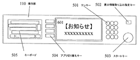
図5は、本実施形態に係る画像形成装置の操作部(図1の110)の詳細を示した図である。なお、図5中の図1と同一の構成については、図1と同一の符号を用い、説明を省略する。本実施形態に係る画像形成装置の操作部110は、表示部111、テンキー501、表示情報取り込み指定キー502、スタートキー503、アプリ切り替えキー504、キーボード505を有している。
FIG. 5 is a diagram showing details of the operation unit (110 in FIG. 1) of the image forming apparatus according to the present embodiment. In FIG. 5, the same components as those in FIG. 1 are denoted by the same reference numerals as those in FIG. The operation unit 110 of the image forming apparatus according to the present embodiment includes a
テンキー501は、コピーの印刷部数の入力等の操作に用いられる。表示情報取り込み指定キー502は、表示部111に表示する装置の操作とは関連しないユーザ指定の任意の情報を取り込む設定の操作に用いられる。スタートキー503は、コピーや原稿読み取りの開始を指示する操作に用いられる。アプリケーション切り替えキー504は、コピー機能/プリンタ機能/スキャナ機能/FAX機能等の機能を切り替える操作に用いられる。106キーボード505は、任意の文字列を入力する操作に用いられ、本実施形態では、ハードキーボードで構成しているが、液晶タッチパネル上に表示されるソフトキーボードで構成しても良い。
A numeric keypad 501 is used for operations such as inputting the number of copies to be printed. The display information import designation key 502 is used for an operation for setting to capture arbitrary information specified by the user that is not related to the operation of the device displayed on the
次にユーザの指定する任意の文字情報を表示部(図1の111)に表示する動作を図1、図5、及び図6を用いて説明する。なお、図6中の図1、及び図5と同一の構成については、図1、及び図5で用いた符号と同一の符号を用い、説明を省略する。 Next, an operation for displaying arbitrary character information designated by the user on the display unit (111 in FIG. 1) will be described with reference to FIGS. 1, 5, and 6. FIG. 6 that are the same as those in FIG. 1 and FIG. 5 are denoted by the same reference numerals as those used in FIG. 1 and FIG.
ユーザは、表示部111に表示したい文字列を、106キーボード505から入力する。入力された情報は、図1に示すキー112からキースキャン回路109を経て、CPU101に読み込まれる。CPU101は、入力された文字列の表示フォントをフォントROM104から読み出し、表示用メモリ107に書き込む。表示用メモリ107に書き込まれたデータは、グラフィックコントローラ108を介して表示部111に送られ、図6中の表示部601のように表示される。
The user inputs a character string to be displayed on the
次に、ユーザの指定する任意のイメージ情報を表示部(図1の111)に表示する動作を図1、図2、図5、及び図7を用いて説明する。なお、図7中の図1、及び図5と同一の構成については、図1、及び図5で用いた符号と同一の符号を用い、説明を省略する。 Next, an operation for displaying arbitrary image information designated by the user on the display unit (111 in FIG. 1) will be described with reference to FIGS. 1, 2, 5, and 7. FIG. 7 that are the same as those in FIG. 1 and FIG. 5 are denoted by the same reference numerals as those used in FIG. 1 and FIG.
ユーザは、表示部111に表示したい画像イメージが描かれた原稿を、図2に示すコンタクトガラス202上に載置し、図5中のスタートキー503を押下することにより、図1に示すCPU101に対して画像の読み取り開始指示を与える。CPU101は、スキャナ制御I/O回路113を操作してスキャナ部114を制御し、原稿の画像を読み取る。読み取られた画像データは、画像メモリ102に蓄積される。CPU101は、画像メモリ102に蓄積された画像データをシステムバス120を介して読み出し、表示用メモリ107に書き込む。表示用メモリ107に書き込まれたデータは、グラフィックコントローラ108を介して表示部111に送られ、図7に示す表示部701のように表示される。
The user places a document on which an image image desired to be displayed on the
(第1の実施形態)
次に、図8〜図10を参照して、本発明の第1の実施形態について説明する。
(First embodiment)
Next, a first embodiment of the present invention will be described with reference to FIGS.
図8は、本実施形態に係るネットワークシステムの構成例である。本実施形態に係るネットワークシステムは、それぞれが機能を異にする装置A800と装置B900とが、互いにネットワークを介して接続されている。
FIG. 8 is a configuration example of the network system according to the present embodiment. In the network system according to the present embodiment, a device A 800 and a
図9は、図8に示す装置A800の構成を示している。装置A800は、CPU801、生成部802、通信部803、解析部804、メモリ805、システムバス806を有している。
FIG. 9 shows a configuration of the apparatus A800 shown in FIG. The apparatus A 800 includes a CPU 801, a
生成部802では、モバイルエージェントが生成される。通信部803は、図8に示す装置B900とのデータ送受信の機能を持つ。なお、送信または受信の少なくとも一方の機能を持つようにしても良い。本実施形態では、生成部802で生成されたモバイルエージェントが、通信部803により装置B900へ送信される。解析部804は、ネットワークシステム全体及びネットワークを構成する各装置の状態を解析する。メモリ805は、通信部803が受信したデータ、モバイルエージェント、または解析部804による解析結果を記憶する。以上の動作制御は、CPU801が、システムバス806を介して行う。
In the
図10は、図8に示す装置B900の構成を示している。装置B900は、CPU901、実行部902、通信部903、機能部904、判断部905、メモリ906、システムバス907を有している。
FIG. 10 shows a configuration of the device B900 shown in FIG. The
実行部902は、モバイルエージェントを実行する機能を持つ。通信部903は、図8に示す装置B900とのデータ送受信の機能を持つ。なお、送信または受信の少なくとも一方の機能を持つようにしても良い。通信部903により受信されたモバイルエージェントは、実行部902により実行される。実行結果は、メモリ906に記憶される。判断部905は、メモリ906に記憶された実行結果を判断し、判断結果に応じて、機能部904が備えた機能を選択する。選択された機能は、CPU901が制御することによって実行される。以上の動作制御は、CPU901が、システムバス907を介して行う。
The
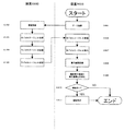
図11は、第1の実施形態に係る処理のフローチャートである。本フローチャートは、モバイルエージェントを生成する機能を持たない装置B900が、モバイルエージェントを生成する機能を有する装置A800に対してモバイルエージェントの生成依頼を行い、生成されたモバイルエージェントを受信し、受信したモバイルエージェントを実行する場合の一例について示したものである。
FIG. 11 is a flowchart of processing according to the first embodiment. In this flowchart, the
はじめに、装置B900は、通信部903を介して、装置A800に対してモバイルエージェント生成に必要なデータを送信する(S1101)。データ送信は、ユーザの指示に従って、送信することとしても良いし、メモリ906に蓄積されたデータに基づいてCPU901が自動的に送信するように制御することとしても良い。装置A800は、通信部803を介して装置B900からデータを受け取ると、解析部804で、装置B900単体、または装置A800及び装置B900を含めたネットワークシステム全体の状態を解析し、解析結果に基づいて、モバイルエージェントの生成に必要な条件を判断する(S1102)。生成部802では、解析部804の処理結果に基づいてモバイルエージェントを生成する(S1103)。生成されたモバイルエージェントは、メモリ805に記憶され(S1104)た後、通信部803を介して、装置B900に送信される(S1105)。
First, the
装置B900は、通信部903を介して、装置A800から送信されてきたモバイルエージェントを受信すると(S1106)、実行部902によりモバイルエージェントを実行する(S1107)。このとき、実行前にモバイルエージェントをメモリ906に記憶しておくことも可能である。実行結果は、メモリ906に記憶され(S1108)、機能部904で、実際に備えている機能と実行結果との対比を行い(S1109)、対比結果に基づいて、装置B900が備える機能の中から最適な機能を選択する(S1110)。このとき機能部904が備えた機能の中に、最適な機能が存在していなかった場合は何も実行せず(S1110で「NO」)にルーチンを終了し、存在していた場合は(S1110で「YES」)、選択した機能を実行して(S1111)ルーチンを終了する。
When the
図12は、図11に示す環境判断(S1102)、及び機能選択(S1110)で用いるデータテーブルの一例である。 FIG. 12 is an example of a data table used in environment determination (S1102) and function selection (S1110) shown in FIG.
テーブル1201には、装置B900が送信するデータの内容、判断結果、判断結果に対して最適なモバイルエージェントプログラムとが、それぞれ対応付けられて記憶されている。テーブル1202には、装置Aが生成したモバイルエージェント、モバイルエージェントの実行結果、実行結果に基づいて選択すべき機能がそれぞれ対応付けられて記憶されている。
The table 1201 stores the contents of data transmitted by the
例えば、装置A800の判断結果が「A」の場合、装置A800はMA−Aというモバイルエージェントを生成する。生成されたモバイルエージェントは、装置B900に送信され、装置Bはモバイルエージェントを解析し、解析結果が「a」となるので、対応する機能であるスキャナ機能を選択することになる。なお、本実施例はほんの一例であり、テーブル1201、及びテーブル1202に記憶するデータは、画像形成装置の機能に限らず、例えばエラーの有無を示す情報のような動的情報に対応付けて記憶するようにしても良い。
For example, when the determination result of the device A 800 is “A”, the device A 800 generates a mobile agent called MA-A. The generated mobile agent is transmitted to the
また、装置A800には、テーブル1201が、予めメモリ805に格納されている。解析部804は、装置B900から受信したデータを参照し、テーブル1201と対比することにより、必要なモバイルエージェントを解析結果として、生成部802へ送る。モバイルエージェント生成後の処理の流れは、図11に示した通りである。
In the device A 800, a table 1201 is stored in the
一方、装置B900には、テーブル1202が、予めメモリ906に格納されている。実行部902は、受信したモバイルエージェントを実行し、その実行結果に基づいて、判断部905が、テーブル1202を参照し、機能部904の備えた機能の中から機能を選択する。機能選択後の処理の流れは、図11に示した通りである。
On the other hand, in the device B900, a table 1202 is stored in the memory 906 in advance. The
なお、本実施形態では、装置B900がデジタル複合機の場合について示したが、モバイルエージェントの実行機能を持っている装置であれば、デジタル複合機に限定されるものではない。また、本実施形態では、S1103で装置A800がモバイルエージェントを生成する場合について示したが、装置A800のメモリ106にモバイルエージェントが記憶されていた場合は、モバイルエージェントを生成する代わりに、装置B900から送られてくるデータに従って、記憶しているモバイルエージェントを最新のものに更新するようにしても良い。
In the present embodiment, the case where the
本実施形態によれば、一方の画像形成装置が、他方の画像形成装置からの要求に応じてモバイルエージェントを生成する手段と生成したモバイルエージェントを送信する手段を有し、他方の画像形成装置が、送信されてきたモバイルエージェントに基づいて機能を実行する手段を有するので、モバイルエージェントの送受信時のみネットワークが接続状態であればよく、またそれぞれの装置がモバイルエージェントの生成または解析処理を行うだけで良い。 According to this embodiment, one image forming apparatus has a means for generating a mobile agent and a means for transmitting the generated mobile agent in response to a request from the other image forming apparatus, and the other image forming apparatus Since it has a means for executing a function based on the transmitted mobile agent, the network only needs to be connected only when the mobile agent is transmitted / received, and each device only generates or analyzes the mobile agent. good.
(第2の実施形態)
次に、図13〜図15を参照して本発明の第2の実施形態について説明する。
(Second Embodiment)
Next, a second embodiment of the present invention will be described with reference to FIGS.
図13は、本実施形態に係るネットワークシステムの構成例である。装置A〜E(1301〜1305)が、それぞれ1または複数の装置とネットワークを介して接続されている。また、本実施形態では、各装置A〜E(1301〜1305)は、後述の図14に示すように、互いに機能は異なるが、少なくとも同一の構成を持っているものとする。 FIG. 13 is a configuration example of the network system according to the present embodiment. Devices A to E (1301 to 1305) are each connected to one or more devices via a network. In the present embodiment, the devices A to E (1301 to 1305) have different functions but have at least the same configuration as shown in FIG. 14 described later.
図14は、図13に示す装置A〜E(1301〜1305)の構成を示している。 FIG. 14 shows the configuration of the devices A to E (1301 to 1305) shown in FIG.
装置A〜E(1301〜1305)は、CPU1401、生成部1402、通信部1403、解析部1404、メモリ1405、実行部1406、機能部1407、判断部1408、システムバス1409を有している。
The apparatuses A to E (1301 to 1305) include a CPU 1401, a
CPU1401は、装置全体の制御を行う。生成部1402では、モバイルエージェントが生成される。通信部1403は、他の装置とのデータ送信または受信の少なくとも一方の機能を持つ。本実施形態では、生成部1402で生成されたモバイルエージェントが、通信部1403により他の装置へ送信される。解析部1404は、ネットワークシステム全体及びネットワークを構成する各装置の状態を解析する。メモリ1405は、通信部1403が受信したデータ、モバイルエージェント、または解析部1404による解析結果を記憶する。
A CPU 1401 controls the entire apparatus. The
実行部1406は、モバイルエージェントを実行する機能を持つ。通信部1403により受信されたモバイルエージェントは、実行部1406により実行される。実行結果は、メモリ1405に記憶される。判断部1408は、メモリ1405に記憶された実行結果を判断し、判断結果に応じて、機能部1407が備えた機能を選択する。選択された機能は、CPU1401が制御することによって実行される。以上の動作制御は、CPU1401が、システムバス1409を介して行う。
The
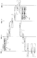
図15は、第2の実施形態に係る処理のシーケンス図である。装置A1301と装置B1302、装置B1302と装置C1303、装置C1303と装置A1301との間だけでの処理は図11に示した通りであるので説明を省略する。本実施形態では、装置A1301と装置D1304のように直接接続されていない装置間での処理の一例として、装置A1301から装置D1304へデータを送信し、装置D1304でモバイルエージェントを生成する場合の例を示す。 FIG. 15 is a sequence diagram of processing according to the second embodiment. The processing only between the device A 1301 and the device B 1302, the device B 1302 and the device C 1303, and the processing between the device C 1303 and the device A 1301 is as shown in FIG. In this embodiment, as an example of processing between devices A1301 and D1304 that are not directly connected, an example in which data is transmitted from device A1301 to device D1304 and a mobile agent is generated by device D1304. Show.
はじめに、装置A1301は、通信部1403を介して、装置B1302に対してモバイルエージェント生成に必要なデータを送信する(S1501)。データ送信は、ユーザの指示に従って、送信することとしても良いし、メモリ1405に蓄積されたデータに基づいてCPU1401が自動的に送信するように制御することとしても良い。本実施形態では、装置A1301が送信するデータには、宛先、要求内容、発信元を含めることとしたが(T1501)、これに限定されるものではない。
First, the device A 1301 transmits data necessary for mobile agent generation to the device B 1302 via the communication unit 1403 (S1501). The data transmission may be performed according to a user instruction, or may be controlled so that the CPU 1401 automatically transmits based on the data stored in the
装置B1302は、通信部1403を介して、装置A1301からデータを受け取ると、解析部1404で受け取ったデータを解析する(S1502)。今回は、装置D1304への送信を要求しているので、装置B1302は、解析結果に基づいて、データを装置D1304へ送信するために、通信部1403を介して装置C1303へ転送する(S1503)。なお、本実施形態では、装置A1301が装置B1302へデータを送信したが、装置A1301から装置C1303へ直接データを送信した場合は、装置B1302における処理(S1502〜S1503)は不要である。
Upon receiving data from the device A 1301 via the
装置C1303は、通信部1403を介して、装置B1302(または装置A1301)からデータを受け取ると、解析部1404で受け取ったデータを解析する(S1504)。本実施形態では、装置D1304への送信を要求しているので、装置C1303は、解析結果に基づいて、通信部1403を介して、データを装置D1304へ転送する(S1505)。
Upon receiving data from the device B 1302 (or device A 1301) via the
装置D1304は、通信部1403を介して、装置C1303からデータを受け取ると、解析部1404で受け取ったデータを解析し(S1506)、解析結果に基づいて、生成部1402でモバイルエージェントを生成する(S1507)。生成したモバイルエージェントは、装置A1301へ返信するため、通信部1403を介して、装置B1302へ送信する(S1508)。本実施形態では、モバイルエージェントに装置A1301へのデータ転送を要求する旨の情報を付加することとしたが(T1502)、これに限定されるものではない。
Upon receiving data from the device C1303 via the
装置B1302は、通信部1403を介して、装置D1304からモバイルエージェントを受け取ると、解析部1404でデータを解析し(S1509)、解析結果に基づいて、通信部1403を介して、装置A1301にモバイルエージェントを転送する(S1510)。
When the device B 1302 receives the mobile agent from the device D 1304 via the
装置A1301は、通信部1403を介して、装置B1302からモバイルエージェントを受け取ると、実行部1406でモバイルエージェントを実行し(S1511)、実行結果に基づいて、機能部1407から判断部1408で必要な機能を選択する(S1512)。選択された機能は、CPU1401が実行するよう制御する(S1513)。
Upon receiving the mobile agent from the device B 1302 via the
本実施形態によれば、複数の画像形成装置が接続された複雑な画像形成システムにおいても、第1の実施形態と同様の効果を奏する。 According to the present embodiment, even in a complex image forming system in which a plurality of image forming apparatuses are connected, the same effects as those of the first embodiment can be obtained.
(第3の実施形態)
次に、図16を参照して、第3の実施形態について説明する。
(Third embodiment)
Next, a third embodiment will be described with reference to FIG.
図16は、第3の実施形態に係る処理のシーケンス図である。本実施形態では、はじめに装置A1301が送信するデータに宛先を含めず、要求内容のみを送信する場合についての一例を示す。 FIG. 16 is a sequence diagram of processing according to the third embodiment. In the present embodiment, an example of a case where only the request content is transmitted without including the destination in the data transmitted by the device A 1301 first is shown.
はじめに、装置A1301は、通信部1403を介して、装置B1302、または装置C1303の少なくとも一方に対してモバイルエージェント生成に必要なデータを送信する(S1601)。データ送信は、ユーザの指示に従って、送信することとしても良いし、メモリ1405に蓄積されたデータに基づいてCPU1401が自動的に送信するように制御することとしても良い。本実施形態では、装置A1301が送信するデータには、要求内容、発信元を含めることとしたが(T1601)、これに限定されるものではない。
First, the device A 1301 transmits data necessary for mobile agent generation to at least one of the device B 1302 and the device C 1303 via the communication unit 1403 (S1601). The data transmission may be performed according to a user instruction, or may be controlled so that the CPU 1401 automatically transmits based on the data stored in the
装置B1302は、通信部1403を介して、装置A1301からデータを受け取ると、解析部1404で受け取ったデータを解析する(S1602)。装置B1302が備えたメモリ1405には、送信可能な隣接する装置とその装置が持つ機能とを対応付けて記憶されている(T1602)。判断部1408は、解析結果から処理の内容を判断する。この場合、テーブルT1602を参照しても、判断がつかないため、隣接する装置で発信元以外の装置である装置C1303へ転送する(S1603)。
Upon receiving data from the device A 1301 via the
装置C1303は、通信部1403を介して、装置B1302(または装置A1301)からデータを受け取ると、解析部1404で受け取ったデータを解析する(S1604)。装置C1303が備えたメモリ1405には、送信可能な隣接する装置とその装置が持つ機能とを対応付けて記憶されている(T1603)。判断部1408は、解析結果から処理の内容を判断する。この場合、テーブルT1603を参照しても、判断がつかないため、隣接する装置で発信(転送)元以外の装置である装置D1304へ転送する(S1605)。
Upon receiving data from the device B 1302 (or device A 1301) via the
装置D1304は、通信部1403を介して、装置C1303からデータを受け取ると、解析部1404で受け取ったデータを解析する(S1606)。装置D1304が備えたメモリ1405には、送信可能な隣接する装置とその装置が持つ機能とを対応付けて記憶されている(T1604)。判断部1408は、解析結果から処理の内容を判断する。この場合、テーブルT1604を参照すると、データeであれば、装置Eに転送すれば良いことが判断できるため、通信部1403を介して、装置E1305へ転送する(S1607)。
Upon receiving data from the device C1303 via the
装置E1305は、通信部1403を介して、装置D1304からデータを受け取ると、解析部1404で受け取ったデータを解析する(S1608)。その後の各装置の処理は、第3の実施形態(S1507〜S1513)と同様のため、説明を省略する。
Upon receiving data from the device D1304 via the
本実施形態によれば、機能を提供する装置が、宛先を意識せずに提供したい機能の要望をするだけで、第1及び第2の実施形態と同様の効果を奏する。 According to the present embodiment, the same effect as the first and second embodiments can be obtained by merely requesting a function to be provided by a device that provides a function without considering the destination.
(第4の実施形態)
図17は、第4の実施形態に係る処理のシーケンス図である。なお、図15と同一の処理については、図15と同一の符号を用い、説明を省略する。
(Fourth embodiment)
FIG. 17 is a sequence diagram of processing according to the fourth embodiment. In addition, about the process same as FIG. 15, the same code | symbol as FIG. 15 is used, and description is abbreviate | omitted.
本実施形態では、装置D1304から装置B1302へのモバイルエージェント送信(S1508)に失敗した場合、モバイルエージェントが戻ってくる(S1701)。次に、モバイルエージェントの生成元である装置D1304は、装置B1302へ戻ってきたモバイルエージェントを再送信する(S1702)。この処理を装置B1302への送信が成功するまで繰り返す(S1703〜S1705)。装置B1302が装置D1304から送信されてきたモバイルエージェントの受信に成功した以後の動作は図15で説明した通りである。 In the present embodiment, when the mobile agent transmission from the device D 1304 to the device B 1302 fails (S1508), the mobile agent returns (S1701). Next, the device D1304 that is the generation source of the mobile agent retransmits the mobile agent that has returned to the device B1302 (S1702). This process is repeated until transmission to the apparatus B 1302 is successful (S1703 to S1705). The operation after the device B 1302 has successfully received the mobile agent transmitted from the device D 1304 is as described with reference to FIG.
(第5の実施形態)
図18は、第5の実施形態に係る処理のシーケンス図である。なお、図15と同一の処理については、図15と同一の符号を用い、説明を省略する。
(Fifth embodiment)
FIG. 18 is a sequence diagram of processing according to the fifth embodiment. In addition, about the process same as FIG. 15, the same code | symbol as FIG. 15 is used, and description is abbreviate | omitted.
本実施形態では、装置D1304から装置B1302へのモバイルエージェント送信(S1508)に失敗した場合、送信先である装置B1302に関する情報(以下、「エラー情報」という)が戻ってくる(S1801)。エラー情報については、後述する(T1801)。次に、モバイルエージェントの生成元である装置D1304は、エラー情報を取得し(S1802)、取得したエラー情報に基づいて送信ルートの再検討を行なう(S1803)。新しい送信ルートが決まると、そのルートでモバイルエージェントを送信する(1804)。装置C1303は、モバイルエージェントの受信に成功すると(S1805)、モバイルエージェントの解析を行い(S1806)、受信したモバイルエージェントを最終的な送信先である装置A1301に転送する(S1807)。 In this embodiment, when the mobile agent transmission from the device D 1304 to the device B 1302 fails (S1508), information (hereinafter referred to as “error information”) regarding the device B 1302 that is the transmission destination is returned (S1801). The error information will be described later (T1801). Next, the device D1304, which is the generation source of the mobile agent, acquires error information (S1802), and reviews the transmission route based on the acquired error information (S1803). When a new transmission route is determined, the mobile agent is transmitted using the route (1804). When the device C1303 succeeds in receiving the mobile agent (S1805), the device C1303 analyzes the mobile agent (S1806), and transfers the received mobile agent to the device A1301, which is the final transmission destination (S1807).
本実施形態では、S1804にて、モバイルエージェントのみを装置C1303に送信する例を説明したが、これに限られるものではない。例えば、S1802で取得したエラー情報(T1801)とともにモバイルエージェントを送信するようにしても良い。 In this embodiment, the example in which only the mobile agent is transmitted to the device C1303 in S1804 has been described, but the present invention is not limited to this. For example, the mobile agent may be transmitted together with the error information (T1801) acquired in S1802.
エラー情報(T1801)は、装置名、その装置の所在(例えば、IPアドレス)、エラーの原因を示すエラーコード、リトライの回数を含む例を説明したが、これに限られるものではない。 The error information (T1801) has been described as an example including a device name, the location of the device (for example, IP address), an error code indicating the cause of the error, and the number of retries, but is not limited thereto.
本実施形態によれば、モバイルエージェントの送信に失敗した場合でも、適切な対応を取ることにより、確実にモバイルエージェントの機能を実行することが可能となるという効果を奏する。 According to this embodiment, even when transmission of a mobile agent fails, there is an effect that it is possible to reliably execute the function of the mobile agent by taking an appropriate response.
101 CPU
102 画像メモリ
103、104 ROM
106 HDD
108 グラフィックコントローラ
110 操作部
114 スキャナ部
116 プリンタ部
117 赤外線通信回路
118 ネットワークI/F
119 モデム
120 システムバス
101 CPU
102
106 HDD
108 Graphic Controller 110
119 Modem 120 System bus
Claims (9)
モバイルエージェントを生成するモバイルエージェント生成手段を備えた第1の画像形成装置と、
前記通信手段により受信した前記モバイルエージェントを解析するモバイルエージェント解析手段を備えた第2の画像形成装置と、
を含むことを特徴とする画像形成システム。 In an image forming system in which a plurality of image forming apparatuses are connected to each other via a network, the image forming apparatus includes a communication unit that performs communication with other apparatuses.
A first image forming apparatus comprising mobile agent generation means for generating a mobile agent;
A second image forming apparatus comprising mobile agent analysis means for analyzing the mobile agent received by the communication means;
An image forming system comprising:
前記第2の画像形成装置は、
前記他の画像形成装置の状態を検知する検知手段と、
前記解析手段による解析結果及び前記検知手段による検知結果に応じて、前記画像形成システムを制御する制御手段と、
を備えたことを特徴とする画像形成システム。 The image forming system according to claim 1.
The second image forming apparatus includes:
Detecting means for detecting a state of the other image forming apparatus;
Control means for controlling the image forming system according to the analysis result by the analysis means and the detection result by the detection means;
An image forming system comprising:
前記第2の画像形成装置は、
前記モバイルエージェントを更新するモバイルエージェント更新手段を備えたことを特徴とする画像形成システム。 The image forming system according to claim 1 or 2,
The second image forming apparatus includes:
An image forming system comprising mobile agent update means for updating the mobile agent.
前記第2の画像形成装置は、
前記モバイルエージェントを自動生成する自動生成手段を備えたことを特徴とする画像形成システム。 The image forming system according to any one of claims 1 to 3,
The second image forming apparatus includes:
An image forming system comprising automatic generation means for automatically generating the mobile agent.
前記制御手段は、
複数の他の前記画像形成装置の相補的な制御を行うことを特徴とする画像形成システム。 The image forming system according to any one of claims 1 to 4,
The control means includes
An image forming system that performs complementary control of a plurality of other image forming apparatuses.
前記第2の画像形成装置は、
前記通信手段により他の画像形成装置から受信した前記モバイルエージェントを該モバイルエージェントが生成された画像形成装置以外の他の画像形成装置に転送するモバイルエージェント転送手段を備えたことを特徴とする画像形成システム。 The image forming system according to any one of claims 1 to 5,
The second image forming apparatus includes:
Image forming apparatus comprising: mobile agent transfer means for transferring the mobile agent received from the other image forming apparatus by the communication means to another image forming apparatus other than the image forming apparatus in which the mobile agent is generated. system.
前記モバイルエージェント転送手段は、
前記解析手段による解析結果及び前記検知手段による検知結果に応じて、前記通信手段により受信した前記モバイルエージェントを他の画像形成装置に転送することを特徴とする画像形成システム。 The image forming system according to claim 6.
The mobile agent transfer means includes
An image forming system, wherein the mobile agent received by the communication unit is transferred to another image forming apparatus in accordance with an analysis result by the analysis unit and a detection result by the detection unit.
前記第1の画像形成装置は、
前記モバイルエージェント生成手段により生成されたモバイルエージェントの送信先となる前記第2の画像形成装置が該モバイルエージェントの受信に失敗した場合、所定のタイミングで該モバイルエージェントの送信を繰り返すリトライ送信手段を備えたことを特徴とする画像形成システム。 The image forming system according to any one of claims 1 to 7,
The first image forming apparatus includes:
Retry transmission means for repeating transmission of the mobile agent at a predetermined timing when the second image forming apparatus that is the transmission destination of the mobile agent generated by the mobile agent generation means fails to receive the mobile agent. An image forming system characterized by that.
前記第1の画像形成装置は、
前記モバイルエージェント生成手段により生成したモバイルエージェントの送信先となる前記第2の画像形成装置が該モバイルエージェントの受信に失敗した場合、該第2の画像形成装置に関する情報を取得して、記憶する記憶手段を備えたことを特徴とする画像形成システム。 The image forming system according to any one of claims 1 to 8,
The first image forming apparatus includes:
A storage that acquires and stores information about the second image forming apparatus when the second image forming apparatus that is a transmission destination of the mobile agent generated by the mobile agent generating unit fails to receive the mobile agent An image forming system comprising means.
Priority Applications (1)
| Application Number | Priority Date | Filing Date | Title |
|---|---|---|---|
| JP2004351665A JP4448765B2 (en) | 2004-12-03 | 2004-12-03 | Image forming system |
Applications Claiming Priority (1)
| Application Number | Priority Date | Filing Date | Title |
|---|---|---|---|
| JP2004351665A JP4448765B2 (en) | 2004-12-03 | 2004-12-03 | Image forming system |
Publications (2)
| Publication Number | Publication Date |
|---|---|
| JP2006165807A true JP2006165807A (en) | 2006-06-22 |
| JP4448765B2 JP4448765B2 (en) | 2010-04-14 |
Family
ID=36667346
Family Applications (1)
| Application Number | Title | Priority Date | Filing Date |
|---|---|---|---|
| JP2004351665A Expired - Fee Related JP4448765B2 (en) | 2004-12-03 | 2004-12-03 | Image forming system |
Country Status (1)
| Country | Link |
|---|---|
| JP (1) | JP4448765B2 (en) |
Cited By (1)
| Publication number | Priority date | Publication date | Assignee | Title |
|---|---|---|---|---|
| EP1919146A2 (en) * | 2006-11-06 | 2008-05-07 | Vodafone Group PLC | Method, system and terminal device for transmitting and receiving messages |
-
2004
- 2004-12-03 JP JP2004351665A patent/JP4448765B2/en not_active Expired - Fee Related
Cited By (2)
| Publication number | Priority date | Publication date | Assignee | Title |
|---|---|---|---|---|
| EP1919146A2 (en) * | 2006-11-06 | 2008-05-07 | Vodafone Group PLC | Method, system and terminal device for transmitting and receiving messages |
| EP1919146A3 (en) * | 2006-11-06 | 2009-12-23 | Vodafone Group PLC | Method, system and terminal device for transmitting and receiving messages |
Also Published As
| Publication number | Publication date |
|---|---|
| JP4448765B2 (en) | 2010-04-14 |
Similar Documents
| Publication | Publication Date | Title |
|---|---|---|
| JP4245755B2 (en) | Information display system for composite image forming apparatus | |
| US6434343B1 (en) | Composite machine, server, composite machine-server system, and program recording medium | |
| JP2001169032A (en) | Digital copying machine, image forming device and slave machine of digital copying machine | |
| JP3760526B2 (en) | Data communication system and data communication control method | |
| JP2008140276A (en) | Information processor and information processing method | |
| JP2018176629A (en) | Image processing device | |
| JP2018107686A (en) | Image processing apparatus, control method and program of the same | |
| JP2005231158A (en) | Job processing apparatus and job processing system | |
| JP6213405B2 (en) | Information processing apparatus, image processing apparatus, and external service usage method | |
| JP4448765B2 (en) | Image forming system | |
| JP2013089982A (en) | Image formation system, image formation apparatus, and program | |
| JP2005119119A (en) | Image forming apparatus and its control method | |
| JP5873895B2 (en) | Image processing apparatus and image processing system | |
| JP3639613B2 (en) | Information processing method, apparatus and system | |
| JP3203171B2 (en) | Image forming device | |
| JP2000305734A (en) | System for forming image and its control method | |
| JP3934640B2 (en) | Image processing system, image forming apparatus, and search program | |
| JP3839985B2 (en) | Image output control device, image output control method, and storage medium storing computer-readable program | |
| JP2001154536A (en) | Image forming device | |
| JPH1188570A (en) | Image forming system | |
| JP4437739B2 (en) | Image forming apparatus and program | |
| JP3566119B2 (en) | Image output device | |
| JP2002044315A (en) | Communication terminal with copy function | |
| JP2012056114A (en) | Image forming device, image forming system and output destination management server | |
| JP2004348372A (en) | Remote control device and image formation system |
Legal Events
| Date | Code | Title | Description |
|---|---|---|---|
| A621 | Written request for application examination |
Free format text: JAPANESE INTERMEDIATE CODE: A621 Effective date: 20071126 |
|
| A977 | Report on retrieval |
Free format text: JAPANESE INTERMEDIATE CODE: A971007 Effective date: 20091015 |
|
| A131 | Notification of reasons for refusal |
Free format text: JAPANESE INTERMEDIATE CODE: A131 Effective date: 20091020 |
|
| A521 | Written amendment |
Free format text: JAPANESE INTERMEDIATE CODE: A523 Effective date: 20091216 |
|
| TRDD | Decision of grant or rejection written | ||
| A01 | Written decision to grant a patent or to grant a registration (utility model) |
Free format text: JAPANESE INTERMEDIATE CODE: A01 Effective date: 20100119 |
|
| A01 | Written decision to grant a patent or to grant a registration (utility model) |
Free format text: JAPANESE INTERMEDIATE CODE: A01 |
|
| A61 | First payment of annual fees (during grant procedure) |
Free format text: JAPANESE INTERMEDIATE CODE: A61 Effective date: 20100125 |
|
| FPAY | Renewal fee payment (event date is renewal date of database) |
Free format text: PAYMENT UNTIL: 20130129 Year of fee payment: 3 |
|
| R150 | Certificate of patent or registration of utility model |
Free format text: JAPANESE INTERMEDIATE CODE: R150 |
|
| FPAY | Renewal fee payment (event date is renewal date of database) |
Free format text: PAYMENT UNTIL: 20140129 Year of fee payment: 4 |
|
| LAPS | Cancellation because of no payment of annual fees |