JP2006158119A - Power steering control device, method and program - Google Patents
Power steering control device, method and program Download PDFInfo
- Publication number
- JP2006158119A JP2006158119A JP2004346726A JP2004346726A JP2006158119A JP 2006158119 A JP2006158119 A JP 2006158119A JP 2004346726 A JP2004346726 A JP 2004346726A JP 2004346726 A JP2004346726 A JP 2004346726A JP 2006158119 A JP2006158119 A JP 2006158119A
- Authority
- JP
- Japan
- Prior art keywords
- pwm
- power steering
- fundamental wave
- control
- signal
- Prior art date
- Legal status (The legal status is an assumption and is not a legal conclusion. Google has not performed a legal analysis and makes no representation as to the accuracy of the status listed.)
- Pending
Links
Images


Classifications
-
- H—ELECTRICITY
- H02—GENERATION; CONVERSION OR DISTRIBUTION OF ELECTRIC POWER
- H02P—CONTROL OR REGULATION OF ELECTRIC MOTORS, ELECTRIC GENERATORS OR DYNAMO-ELECTRIC CONVERTERS; CONTROLLING TRANSFORMERS, REACTORS OR CHOKE COILS
- H02P27/00—Arrangements or methods for the control of AC motors characterised by the kind of supply voltage
- H02P27/04—Arrangements or methods for the control of AC motors characterised by the kind of supply voltage using variable-frequency supply voltage, e.g. inverter or converter supply voltage
- H02P27/06—Arrangements or methods for the control of AC motors characterised by the kind of supply voltage using variable-frequency supply voltage, e.g. inverter or converter supply voltage using dc to ac converters or inverters
- H02P27/08—Arrangements or methods for the control of AC motors characterised by the kind of supply voltage using variable-frequency supply voltage, e.g. inverter or converter supply voltage using dc to ac converters or inverters with pulse width modulation
-
- B—PERFORMING OPERATIONS; TRANSPORTING
- B62—LAND VEHICLES FOR TRAVELLING OTHERWISE THAN ON RAILS
- B62D—MOTOR VEHICLES; TRAILERS
- B62D5/00—Power-assisted or power-driven steering
- B62D5/04—Power-assisted or power-driven steering electrical, e.g. using an electric servo-motor connected to, or forming part of, the steering gear
- B62D5/0457—Power-assisted or power-driven steering electrical, e.g. using an electric servo-motor connected to, or forming part of, the steering gear characterised by control features of the drive means as such
- B62D5/046—Controlling the motor
- B62D5/0463—Controlling the motor calculating assisting torque from the motor based on driver input
Abstract
Description
本発明は詳しくは、PWM基本波の複数周期毎に同期して割り込み処理を行うことにより、信号処理の負担を軽減可能なパワーステアリング制御装置、方法、およびプログラムに関する。 More specifically, the present invention relates to a power steering control device, method, and program capable of reducing the load of signal processing by performing interrupt processing in synchronization with a plurality of periods of a PWM fundamental wave.
自動車用の補助操舵装置として、電動モータのトルクを用いた電動パワーステアリング装置が利用されている。このパワーステアリング装置は、ドライバによるハンドルの操作および車の動きを検出するトルクセンサと、トルクセンサからの検出信号に基づき補助操舵力を演算する電動パワーステアリング制御ユニット(ECU)と、ECUからの出力信号に基づき回転トルクを発生する電動モータと、回転トルクをステアリング機構に伝える減速ギア等を備えて構成されている。 As an auxiliary steering device for an automobile, an electric power steering device using the torque of an electric motor is used. This power steering device includes a torque sensor that detects a steering operation and a vehicle movement by a driver, an electric power steering control unit (ECU) that calculates an auxiliary steering force based on a detection signal from the torque sensor, and an output from the ECU. An electric motor that generates rotational torque based on the signal, a reduction gear that transmits the rotational torque to the steering mechanism, and the like are provided.
このように構成されたパワーステアリング装置において、ドライバがステアリングを操舵すると、トルクセンサにトルクが印加され、トルクの強さに応じたトルク信号がECU内のA/Dコンバータに出力される。ECUはA/D変換されたトルク信号に基づき電流指令値を算出し、この電流指令値に応じたパルス幅変調(以下、PWMという)を行うことにより、モータ駆動電流を生成する。このモータ駆動電流をモータに供給することにより、操舵補助トルクがステアリングに印加される。 In the power steering apparatus configured as described above, when the driver steers the steering, torque is applied to the torque sensor, and a torque signal corresponding to the strength of the torque is output to the A / D converter in the ECU. The ECU calculates a current command value based on the A / D converted torque signal, and generates a motor drive current by performing pulse width modulation (hereinafter referred to as PWM) according to the current command value. By supplying this motor drive current to the motor, steering assist torque is applied to the steering.
上述のように、ECUはPWM処理、トルク信号等のA/D変換、電流指令値演算、フェールセーフ機能等、様々な処理を適切なタイミングで実行しなければならない。特に、ブラシレスモータの制御は、演算量および演算周期の点において多大な演算負荷および割込処理を必要とする。ところが、割込処理を無制限に許容したのでは、演算装置の処理負担が増大し、安定した制御が困難になってしまう。 As described above, the ECU must execute various processes such as PWM processing, A / D conversion of torque signals, current command value calculation, fail-safe function, and the like at appropriate timing. In particular, the control of a brushless motor requires a large calculation load and interrupt processing in terms of calculation amount and calculation cycle. However, if the interrupt processing is allowed without limitation, the processing load of the arithmetic device increases, and stable control becomes difficult.
例えば、PWM処理の周期を50μsecのように短く設定し、PWMコントローラからの割込機能を用いてモータ制御のタイミングを決定した場合、PWM基本波の山または谷のタイミングでAD変換をしなければならず、ECUの演算処理が過大になってしまう。また、モータ制御のタイミングが50μsec以外の周期、すなわち250μsec、500μsecであれば、無用な割込が多く発生してしまい、ECUの演算能力を浪費してしまう。 For example, if the PWM processing cycle is set to a short value of 50 μsec and the motor control timing is determined using the interrupt function from the PWM controller, AD conversion must be performed at the peak or valley timing of the PWM fundamental wave. In other words, the computation processing of the ECU becomes excessive. Further, if the motor control timing is a cycle other than 50 μsec, that is, 250 μsec or 500 μsec, many unnecessary interrupts are generated, and the calculation capacity of the ECU is wasted.
一方、車載用のECUとして、ネットワーク上の通信、故障診断等の機能は1msecの整数倍の基本周期で実行されているため、モータ制御以外の処理は1msecの基本周期で実行する必要がある。モータ制御およびモータ制御以外の処理が干渉せずに実行されるように、モータ制御の周期を整数倍した値が1msecとなる必要がある。
以上のように多くの設計条件を満足させながら、モータ制御を効率良く実行可能なECUの開発が望まれる。
On the other hand, as functions for in-vehicle ECUs, functions such as communication on the network and fault diagnosis are executed with a basic cycle that is an integer multiple of 1 msec, so processes other than motor control must be executed with a basic cycle of 1 msec. A value obtained by multiplying the cycle of the motor control by an integer must be 1 msec so that the processes other than the motor control and the motor control are executed without interference.
As described above, it is desirable to develop an ECU that can efficiently execute motor control while satisfying many design conditions.
従来のパワーステアリング制御装置として、例えば特開平8−207804号公報に記載の発明が案出されている。この装置は、モータをPWM駆動する際に可聴周波数範囲外のPWM信号を用いることにより、可聴周波数範囲内の雑音を軽減することを目的としている。しかしながら、かかる装置は、単に可聴周波数範囲外のPWM信号を用いてモータを駆動するにすぎず、複数の処理を効率よく行うことを目的としたものではない。 As a conventional power steering control device, for example, an invention described in JP-A-8-207804 has been devised. This device is intended to reduce noise within the audible frequency range by using a PWM signal outside the audible frequency range when the motor is PWM driven. However, such a device merely drives a motor using a PWM signal outside the audible frequency range, and is not intended to efficiently perform a plurality of processes.
また、特開2002−272179号公報に記載の装置によれば、パルス幅の中央位置において駆動電流検出信号を読み込むことにより、パルス幅の変化によらずに駆動電流の検出精度を高めることができるというものである。すなわち、当該装置は、パルス幅の一定のタイミングにおいて駆動電流を検出することにより、検出精度の劣化を回避することを目的としている。しかしながら、この装置は、制御装置の処理負担を軽減することを目的としたものではない。また、A/D変換、制御の処理は、PWM周期毎に実行されており、本願発明のようにPWMの複数周期毎にA/D変換、制御演算処理を実行する構成は何等開示されていない。すなわち、この装置によれば、PWM周期毎にA/D変換、制御演算処理するため、装置の処理負担が過大となり、安定した制御を行うことが困難となるおそれがある。 Further, according to the apparatus described in Japanese Patent Application Laid-Open No. 2002-272179, by reading a drive current detection signal at the center position of the pulse width, it is possible to improve the detection accuracy of the drive current regardless of the change in the pulse width. That's it. That is, the object of the device is to avoid deterioration in detection accuracy by detecting the drive current at a constant timing of the pulse width. However, this device is not intended to reduce the processing load on the control device. In addition, the A / D conversion and control processing is executed for each PWM cycle, and no configuration is disclosed for executing A / D conversion and control calculation processing for each of a plurality of PWM cycles as in the present invention. . That is, according to this apparatus, since A / D conversion and control calculation processing are performed every PWM cycle, the processing load on the apparatus becomes excessive, and it may be difficult to perform stable control.
また、特開2002―267237号公報には、指令値に対する検出値のPI制御の演算周期を、2相−3相変換によりデューティ指令値を演算する周期のn倍にする構成が開示されている。しかしながら、この公報には、PWM周期とA/D変換タイミングおよび制御演算タイミングとの関係は開示されていない。 Japanese Patent Laid-Open No. 2002-267237 discloses a configuration in which the PI control calculation cycle of the detected value with respect to the command value is set to n times the cycle of calculating the duty command value by two-phase to three-phase conversion. . However, this publication does not disclose the relationship between the PWM period, A / D conversion timing, and control calculation timing.
さらに、特開2003−231476号公報には、PWM駆動周波数とレゾルバの励磁周波数のうちいずれか一方を他方の整数倍にする装置が開示されている。しかしながら、この公報には、PWM周期とA/D変換タイミングおよび制御開始タイミングとの関係は何等言及されていない。
本発明は上述の問題に鑑みてなされたものであり、本発明の解決しようとする課題は、PWM基本波の複数周期に同期してA/D変換処理、制御演算処理を実行することにより、演算負荷を軽減することをその目的としている。 The present invention has been made in view of the above problems, and the problem to be solved by the present invention is to execute A / D conversion processing and control calculation processing in synchronization with a plurality of periods of a PWM fundamental wave. Its purpose is to reduce the computation load.
上述の課題を解決するために、本発明は、ステアリングに印加された操舵トルクに基づき、モータを駆動するための駆動電流目標値を演算するとともに、当該制御目標電流値に基づき、所定のPWM基本波を用いてパルス幅変調されたPWM駆動電流をステアリングに印加するパワーステアリング制御装置において、前記操舵トルクを表すトルク信号、前記PWM駆動電流を表す信号、前記モータの端子電圧を表す信号の少なくとも一つを読み込む読込手段と、前記読込手段によって読み込まれた信号に基づき前記目標電流値を算出する制御処理手段とを備え、前記読込手段および前記制御処理手段は、前記PWM基本波の複数倍の周期で処理を実行する。 In order to solve the above-described problem, the present invention calculates a drive current target value for driving a motor based on a steering torque applied to a steering, and also calculates a predetermined PWM basic value based on the control target current value. In a power steering control device that applies a PWM drive current pulse-modulated using a wave to a steering, at least one of a torque signal representing the steering torque, a signal representing the PWM drive current, and a signal representing a terminal voltage of the motor Reading means, and control processing means for calculating the target current value based on the signal read by the reading means, wherein the reading means and the control processing means have a period that is a multiple of the PWM fundamental wave. Execute the process.
前記読込手段および前記制御処理手段は、前記PWM基本波の複数倍の周期であって、前記PWM基本波における一定のタイミングで処理を実行する。
また、前記読込手段および前記制御処理手段の少なくともいずれかは、割込処理によって処理を開始する。前記制御処理手段は、前記読込手段における処理が終了した後に処理を実行する。前記読込手段は、所定時間内に処理を終了できなかった場合には、処理の異常を判断する。
The reading unit and the control processing unit execute a process at a fixed timing in the PWM fundamental wave, which has a period that is a multiple of the PWM fundamental wave.
Further, at least one of the reading unit and the control processing unit starts processing by interrupt processing. The control processing unit executes the process after the process in the reading unit is completed. The reading means determines a processing abnormality when the processing cannot be completed within a predetermined time.
前記モータに設けられたレゾルバに対して、前記PWM基本波に同期した励磁信号を供給し、前記読込手段によって前記レゾルバからの検出信号を読み込む。
前記読込手段は、A/Dコンバータからなる。
An excitation signal synchronized with the PWM fundamental wave is supplied to a resolver provided in the motor, and a detection signal from the resolver is read by the reading means.
The reading means comprises an A / D converter.
また、本発明は、ステアリングに印加された操舵トルクを検出するトルクセンサからのトルク信号、および補助トルク発生用のモータへの駆動電流を表す駆動電流信号の少なくともいずれかをA/D変換するA/Dコンバータと、前記トルク信号および前記駆動電流信号に基づき制御目標電流値を演算する制御処理部と、前記制御目標電流値に基づき、所定周波数のPWM基本波を用いて正相および逆相のPWMパルス信号を生成するとともに、2つの前記スイッチ素子が同時にオフとなるデッドタイムを前記正相および/または逆相のPWMパルス信号に付加するPWMコントローラと、前記制御目標値に従いPWMでゅーティ指令値を演算するデューティ指令値演算部と、高電位と低電位との間に接続されるとともに、前記PWMパルス信号に基づき相補動作を行うことにより前記駆動電流を生成する2つのスイッチ素子を少なくとも備えた電流駆動回路とを有し、前記A/Dコンバータは前記デッドタイムに相当する時間内においてA/D変換を実行する。 In the present invention, A / D conversion is performed for at least one of a torque signal from a torque sensor that detects a steering torque applied to the steering and a drive current signal that represents a drive current to a motor for generating auxiliary torque. / D converter, a control processing unit that calculates a control target current value based on the torque signal and the drive current signal, and a positive phase and a reverse phase using a PWM fundamental wave of a predetermined frequency based on the control target current value A PWM controller that generates a PWM pulse signal and adds a dead time during which the two switch elements are simultaneously turned off to the normal-phase and / or reverse-phase PWM pulse signal, and a PWM duty command according to the control target value A duty command value calculation unit for calculating a value, and connected between a high potential and a low potential, and the PWM pulse A current drive circuit including at least two switch elements that generate the drive current by performing complementary operations based on the signal, and the A / D converter performs A / D conversion within a time corresponding to the dead time Execute.
前記A/Dコンバータは、前記PWM基本波の複数周期毎であって、前記PWM基本波における一定のタイミングで処理を実行する。
また、前記制御処理部は、前記A/Dコンバータにおける処理が終了した後に処理を開始する。前記制御処理部は、前記PWM基本波の複数周期毎に、制御目標電流値を更新する。さらに、前記PWM基本波の周期の整数倍が略1msecに設定される。
The A / D converter executes processing at a certain timing in the PWM fundamental wave every plural cycles of the PWM fundamental wave.
The control processing unit starts processing after the processing in the A / D converter ends. The control processing unit updates a control target current value for each of a plurality of periods of the PWM fundamental wave. Further, an integer multiple of the period of the PWM fundamental wave is set to approximately 1 msec.
前記制御処理部の実行周期の逆数が割り切れる値である。また、前記PWM基本波のデューティを決定するためのデューティレジスタを備え、当該デューティレジスタの更新周期が前記制御処理手段によるデューティ演算周期よりも短い。 The reciprocal of the execution period of the control processing unit is a divisible value. In addition, a duty register for determining the duty of the PWM fundamental wave is provided, and an update period of the duty register is shorter than a duty calculation period by the control processing unit.
さらに、ステアリングに印加された操舵トルクに基づき、モータを駆動するための駆動電流の制御目標電流値を演算するとともに、当該制御目標電流値に基づき、所定のPWM基本波を用いてパルス幅変調されたPWM駆動電流をステアリングに印加するパワーステアリング制御装置において、前記操舵トルクを表すトルク信号、前記PWM駆動電流を表す信号、前記モータの端子電圧を表す信号の少なくとも一つをA/D変換し、読み込む読込手段と、前記読込手段によって読み込まれた信号に基づき前記目標電流値を算出する制御処理手段とを備え、前記読込手段は前記PWM基本波の周期の1/2以下の時間内においてA/D変換を完了する。 Furthermore, the control target current value of the drive current for driving the motor is calculated based on the steering torque applied to the steering, and the pulse width is modulated using a predetermined PWM fundamental wave based on the control target current value. In the power steering control device for applying the PWM drive current to the steering, at least one of a torque signal representing the steering torque, a signal representing the PWM drive current, and a signal representing the terminal voltage of the motor is A / D converted, Read means for reading, and control processing means for calculating the target current value based on the signal read by the read means, wherein the read means is A / A within a time equal to or less than ½ of the period of the PWM fundamental wave. Complete D conversion.
本発明によれば、読込手段は、トルク信号、PWM駆動電流を表す信号、モータの端子電圧を表す信号の少なくとも一つを読み込み、読込手段によって読み込まれた信号に基づき電流目標値を算出する。これらの読込手段および制御処理手段は、PWM基本波の複数周期毎に処理を実行するので、PWM基本波の周期毎に処理をする場合に比べ、演算負荷を軽減することが可能となる。このため、安定したパワーステアリング制御を実現できる。 According to the present invention, the reading means reads at least one of a torque signal, a signal representing the PWM drive current, and a signal representing the motor terminal voltage, and calculates a current target value based on the signal read by the reading means. Since these reading means and control processing means execute processing every plural cycles of the PWM fundamental wave, it is possible to reduce the calculation load compared to the case where processing is performed every cycle of the PWM fundamental wave. For this reason, stable power steering control can be realized.
また、PWM基本波の複数周期毎であって、PWM基本波における一定のタイミングで読込処理および制御処理を実行することにより、無用な割込を最小限に抑えることが可能となる。 In addition, by executing the reading process and the control process at a plurality of periods of the PWM fundamental wave and at a constant timing in the PWM fundamental wave, it is possible to minimize unnecessary interrupts.
さらに、制御処理手段は、読込手段における処理が終了した後に処理を実行し、読込手段は、所定時間内に処理を終了できなかった場合には、処理を強制終了する。よって、何らかの異常により、読込処理に長時間を要した場合であっても、制御処理および他の処理の時間が圧迫されることがない。 Further, the control processing unit executes the process after the process in the reading unit is completed, and the reading unit forcibly ends the process when the process cannot be completed within a predetermined time. Therefore, even if the reading process takes a long time due to some abnormality, the time for the control process and other processes is not compressed.
モータに設けられたレゾルバに対して、PWM基本波に同期した励磁信号を供給し、読込手段によってレゾルバからの検出信号を読み込むことにより、他の信号と同タイミングで検出信号を読み込むことができる。 By supplying an excitation signal synchronized with the PWM fundamental wave to the resolver provided in the motor and reading the detection signal from the resolver by the reading means, the detection signal can be read at the same timing as other signals.
さらに、本発明の他の態様によれば、PWMコントローラは2つのスイッチ素子が同時にオフとなるデッドタイムをPWMパルス信号に付加し、A/Dコンバータはデッドタイムに相当する時間内にA/D変換を実行する。モータの駆動電流が安定するのはデッドタイム程度の時間であるので、この時間内に駆動電流のA/D変換を実行することにより、駆動電流を安定に検出することが可能となる。 Further, according to another aspect of the present invention, the PWM controller adds a dead time during which the two switch elements are simultaneously turned off to the PWM pulse signal, and the A / D converter performs the A / D within the time corresponding to the dead time. Perform the conversion. Since the drive current of the motor is stabilized for about the dead time, the drive current can be stably detected by performing A / D conversion of the drive current within this time.
また、A/Dコンバータは、PWM基本波の複数周期毎であって、PWM基本波における一定のタイミングで処理を実行することにより、無用な割込処理を最小限に抑えることが可能となる。 Further, the A / D converter can perform unnecessary interrupt processing to a minimum by executing processing at a certain timing in the PWM fundamental wave every plural cycles of the PWM fundamental wave.
さらに、PWM基本波の周期の整数倍が略1msecに設定される。このため、車載用ECUにおけるモータ制御以外の処理との干渉を回避しながらモータ制御を実行することができる。 Furthermore, an integer multiple of the period of the PWM fundamental wave is set to approximately 1 msec. For this reason, motor control can be executed while avoiding interference with processes other than motor control in the in-vehicle ECU.
また、制御処理部の実行周期の逆数を割り切れる値にすることにより、ディジタルフィルタの係数の誤差を低減することが可能となる。さらに、デューティレジスタの更新周期を制御処理手段によるデューティ演算周期よりも短くすることにより、安定した制御を行うことができる。 Further, by making the reciprocal of the execution period of the control processing unit divisible, it is possible to reduce the error of the digital filter coefficient. Furthermore, stable control can be performed by making the update cycle of the duty register shorter than the duty calculation cycle by the control processing means.
また、読込手段はPWM基本波の周期の1/2以下の時間内においてA/D変換を完了するため、安定した制御を行うととともに、A/D変換のタイミング管理を容易に行うことが可能となる。 In addition, since the reading means completes A / D conversion within a time of 1/2 or less of the period of the PWM fundamental wave, it is possible to perform stable control and easily manage the timing of A / D conversion. It becomes.
以下に、図面を参照しながら本発明の最良の実施の形態を説明する。
(第1実施形態)
図1は、本実施形態に係る電動パワーステアリング装置の概略図である。この図において、ステアリング61はステアリングシャフト62、ユニバーサルジョイント63、64、シャフト65を介してラック&ピニオン66に連結されている。さらに、ラック&ピニオン66には車輪のタイロッド6cが設けられており、ハンドル61の回転運動はタイロッド67の軸方向の運動に変換される構造となっている。
The best mode for carrying out the present invention will be described below with reference to the drawings.
(First embodiment)
FIG. 1 is a schematic diagram of an electric power steering apparatus according to the present embodiment. In this figure, a
シャフト65にはトルクセンサ4が設けられており、トルクセンサ4はステアリング61に印加された操舵トルクを検出し、トルク信号を出力可能である。さらに、シャフト65には減速ギア31、モータ3が取り付けられており、モータ3の回転トルクが減速ギア8を介してシャフト9aに伝達される構成となっている。
A
ECU1は上述のようにトルクセンサ4からのトルク信号、車速センサ2からの車速信号に基づき補助操舵トルクを算出し、この算出結果に基づく駆動電流をモータ3に送出するものである。ECU1にはイグニッションキー5aを介して電源5が接続されており、イグニッションキー5aをオンにすることによりECU1に電流が供給される構成となっている。
The
図2はECU1のハードウェア構成を表すブロック図である。ECU1は、バス100、A/Dコンバータ110,インタフェース111,クロック発生回路12,CPU113,ROM114,RAM115、RDコンバータ116,PWMコントローラ117,モータ駆動回路118、モータ電流検出回路120、121を備えて構成されている。
FIG. 2 is a block diagram illustrating a hardware configuration of the
バス100はA/Dコンバータ110、I/F111、クロック発生回路112、CPU113、ROM114、RAM115等の間でデータの送受信を行うためのものである。A/Dコンバータ110は、トルクセンサ4から出力されたメイントルク信号およびサブトルク信号、モータ電流検出回路120、121からの検出電流、RDコンバータ116からのモータ回転角信号、モータ3の端子電圧を入力し、ディジタル信号に変換するためのものである。
The
上述のトルクセンサ4は、メイントルク信号、サブトルク信号の2つの出力信号を備え、これらの信号の合計電圧は一定電圧(例えば5V)であるクロス特性となるように設定されている。すなわち、ステアリングにトルクが印加されない場合には、メイントルク信号およびサブトルク信号はそれぞれトルク中立電圧2.5Vとなり、ステアリングに何らかのトルクが印加された場合には、メイントルク信号およびサブトルク信号は中立電圧2.5Vを基準として互いに逆方向に変動する。
The
インタフェース111は車速センサ2からの車速パルスをカウントしディジタル信号に変換するものである。ROM114はモータ3の制御プログラム、PWMの演算プログラム、フェールセーフプログラム等を記憶するためのメモリとして使用され、RAM115は当該プログラムを動作させるためのワークメモリとして使用される。
The
PWMコントローラ117はモータ3のトルクを表す信号をパルス幅変調されたパルス信号W,V,U,Wb,Vb,Ubに変換するためのものである。ここで、パルス信号W,V,Uは正相の三相信号を表し、パルス信号Wb,Vb,Ubは逆相の三相信号を表している。
The
モータ駆動回路118は、WVUの三相電流を発生させるための3つのインバータ回路より構成され、各インバータ回路は電源電圧側(上段)のスイッチングトランジスタと接地電位側(下段)のスイッチングトランジスタを有している。上段のスイッチングトランジスタのゲートには、正相のパルス信号W,V,Uが入力され、下段のスイッチングトランジスタには逆相のパルス信号Wb,Vb,Ubが入力されている。すなわち、上段、下段のスイッチングトランジスタは相補接続されており、交互にオン、オフ動作を繰り返すことにより、所望のパルス幅の駆動電流Iu、Iv、Iwを生成する。なお、上段のスイッチングトランジスタと下段のスイッチングトランジスタとが同時にオンにならないように、両者がオフになる時間(デッドタイム)が正相のパルス信号W,V,Uと逆相のパルス信号Wb,Vb,Ubのオンの時間の前後に設けられている。このように、デッドタイムを設けることにより、上段、下段のスイッチングトランジスタの短絡を回避することができる。
The
モータ電流検出回路120、121は抵抗等の電流−電圧変換素子から構成され、モータ3への駆動電流Iu、Iwを検出し、電流に応じた電圧をA/Dコンバータ110に出力可能である。RDコンバータ116は、励磁電流をレゾルバ31に与えるとともに、レゾルバ31からの出力信号を回転角信号としてA/Dコンバータ110に出力する機能を有している。
The motor
図3に、ECU1の機能ブロック図を示す。この図において、電流指令値演算部12、加算器13,電流制御部14、故障診断部15はECU1内のCPU113によって機能するものである。
FIG. 3 shows a functional block diagram of the
電流指令値演算部12は、トルク信号T、車速信号、モータの検出電流i、操舵角信号、および検出電圧eに基づき電流指令値Iを演算する機能を有している。この電流指令値Iはモータ3に供給する駆動電流値を表しており、電流指令値Iに等しい駆動電流がモータ3に供給されるような制御が行われる。また、電流指令値演算部12には車速センサ2からの車速パルスが入力されており、車速に応じた操舵補助力を決定することが可能である。
The current command
また、電流指令値演算部12は、ハンドル戻り補償、モータ最大電流制御を有している。例えば、ハンドル戻り補償は、ステアリング9を中立位置に復元させるための制御を行うものである。一般に、電動パワーステアリング装置においては、減速ギア8等の影響によりセルフアライニングトルクが弱くなり易く、このためにハンドルが中立位置に戻り難くなってしまう。そこで、セルフアライニングトルクの作用によってモータ3が回転させられる際のモータの端子電圧eおよびモータ電流iを検出することによりモータ角速度を検出し、ハンドルを中立位置に復元させるための補償電流値を算出している。
The current command
モータ電流検出回路120、121はモータ3に供給された電流を検出し、検出電流iの信号を出力する。この検出電流iは加算器13にフィードバックされるとともに、電流指令値演算部12に入力される。加算器13は検出電流iと電流指令値Iとの偏差Δiを算出し、電流制御部14に出力する。
The motor
電流制御部14は、微分演算器、比例演算器、積分演算器から構成され、偏差Δiがゼロとなるような制御を行う機能を有している。微分補償器は制御の応答速度を改善するために設けられており、比例演算器は偏差Δiと所定の比例係数との乗算を行うためのものである。さらに、積分演算器は偏差Δiの時間軸で積分値を算出し、偏差Δiの定常値がゼロとなるような制御を行うためのものである。
The
故障診断部15は、モータ3、トルクセンサ4等の異常を検出し、所定のフェールセーフ処理を実行するためのものである。例えば、故障診断部10がトルクセンサ4の異常を検出した場合には割込を発生させ、補助トルクの漸減処理を行うように電流指令値演算部12に指示を与えることができる。
The
図4は、PWMコントローラ117の機能ブロック図である。PWMコントローラ117は、PWM基本タイマ161、三角波発生部162、比較部163、デッドタイムレジスタ164、コンペアレジスタ163を備えて構成されている。PWM基本タイマ161は、クロック周波数をカウントすることによりPWM基本波(キャリア)の周期を算出するためのものである。車載用ECUは一般に1msec周期にて実行されるため、PWM基本波の周期の整数倍が1msecとなるように、例えば、PWM基本波の周期は50μsecに設定されることが望ましい。
FIG. 4 is a functional block diagram of the
三角波発生部162はPWM基本タイマ161でカウントされた値に基づきPWM基本波である三角波を発生させるためのものである。コンペアレジスタ165はPWMデューティ比のデータを格納するためのレジスタであり、W,V,U相の各々毎の3つのレジスタより構成されている。PWMデューティ比はモータの制御目標電流値を表しており、制御処理部160から50μsec毎に与えられるものである。デッドタイムレジスタ164はデッドタイムを表すデータを格納するためのレジスタである。すなわち、デッドタイムレジスタ164の値を変更することにより、所望のデッドタイムを設定することができる。
The
比較部163は、三角波発生部162によって生成された三角波とコンペアレジスタ165に格納されたデューティ比とを比較し、所定幅のパルス信号W,V,U,Wb,Vb,Ubを生成するためのものである。例えば、図5、図6に示されたように、三角波とデューティ比との大小に基づき、正相、逆相のパルスが生成される。PWM基本波である三角波の周期はたとえば50μsecに設定されている。上述のように、コンペアレジスタ165の値は、PWM基本波の複数倍の周期(例えば250μsec)の決まったタイミング(三角波の山または谷)に制御処理部160によって書き換えられる。比較部163は、コンペアレジスタ165に格納されたデューティ比と三角波とを比較し、デューティ比に応じたパルス幅(例えば5μsec)のパルス信号を出力する。なお、コンペアレジスタ165若しくはデューティレジスタ(未図示)のデューティ比の更新周期は、制御処理部165によるデューティの演算周期よりも短いことが望ましい。これにより、安定した制御を行うことが可能となる。
The
図5,図6において、コンペアレジスタ165のデューティ比は50%から25%に変化しており、パルス幅も同様に変化しているのが確認できる。また、図6はデューティ比が50%から100%に変化した場合のパルス信号を表している。
5 and 6, the duty ratio of the compare
さらに、比較部163は、デッドタイムレジスタ164の値に応じたデッドタイムをパルス信号に付加する。すなわち、図5,6に示されるように、比較部163は、正相の立ち上がり時間および逆相の立ち上がり時間を所定時間dだけずらすことにより、デッドタイムdを設ける。これにより、正相、逆相のパルス信号が同時にオンになることを防止することが可能となる。
Further, the
制御開始タイマ166は、モータ駆動電流の演算処理の開始を決定するためのタイマである。制御開始タイマ166はPWM基本タイマ161に同期しており、PWM基本タイマ161の周期50μsecの5倍(250μsec)の周期でリセットされる。また、制御開始タイマ166はA/D変換終了時に割込を発生させるように、初期タイマ値がセットされる。また、A/D開始タイマ160はA/D変換の開始時を決定するためのタイマである。例えば、三角波の山または谷のタイミングでA/D開始タイマ167をリセットし、タイマリセット周期を三角波の周期の5倍(250μsec)に設定することが望ましい。すなわち、A/D開始タイマ160は、三角波の周期の5倍の250μsecの周期であって、三角波の谷の時刻にA/D開始割込を発生する。このように、A/D変換の開始時を三角波の山または谷に同期させることにより、不要な割り込み処理の発生を抑え、演算装置に対する負荷を軽減することが可能となる。
The control start
また、本実施例では、A/Dコンバータ110が複数チャネルの信号をA/D変換可能である場合には、全てのチャネルのA/D変換をPWM基本波の1/2の周期内に終了させることが望ましい。これにより、安定した制御が可能になり、また、A/D変換処理のタイミングを管理することも容易となる。
Further, in this embodiment, when the A /
さらに、制御処理部165の処理周期をTsとおいた場合、1/Tsが割り切れるようにTsの値を設定すると良い。このような値にTsを設定することにより、制御処理部165において使用されるディジタルフィルタの係数をより少ない有効数字桁数で表すことができ、ROM等に記録されたフィルタ係数の誤差を少なくすることが可能となる。
Furthermore, when the processing cycle of the
なお、パルス信号のデューティ比が0,100%近辺では、パルス信号W,V,U,Wb,Vb,Ubのパルス幅はデッドタイム程度の短い時間となってしまう。このため、モータ端子電圧等のA/D変換に要する時間も極力短いことが望ましく、少なくともデッドタイムと同程度の時間内にA/D変換処理を終了させると良い。例えば、デッドタイムが3μsecである場合には、A/D変換処理時間も同様に3μsec程度に設定することができる。そして、当該時間内にA/D変換が終了しなければ、A/D変換処理を強制終了し、異常が発生したと判断しても良い。 When the duty ratio of the pulse signal is in the vicinity of 0, 100%, the pulse widths of the pulse signals W, V, U, Wb, Vb, Ub are as short as the dead time. For this reason, it is desirable that the time required for A / D conversion of the motor terminal voltage or the like is as short as possible, and the A / D conversion processing should be completed within at least the same time as the dead time. For example, when the dead time is 3 μsec, the A / D conversion processing time can be similarly set to about 3 μsec. If the A / D conversion is not completed within the time, the A / D conversion process may be forcibly terminated and it may be determined that an abnormality has occurred.
割込コントローラ168は割込処理を制御するためのものであり、PWM基本タイマ161、制御開始タイマ166、A/D開始タイマ167等によるタイマ割り込みの他、ハードウェア割り込み等の各割り込み処理の優先順位、許可、非許可を行う。例えば、制御開始タイマ166によるタイマ割り込みが発生すると、割込コントローラ168は制御処理部160に駆動電流の演算制御を実行させ、A/D開始タイマ167によるタイマ割り込みが発生すると割込コントローラ168は制御処理部160にA/D変換処理の割り込み処理を行わせる。また、制御開始タイマ166の優先順位は、A/D開始タイマ167の優先順位よりも高く設定されており、両者の割込処理が競合した場合には、割込コントローラ168は制御開始タイマ166の割込を優先的に処理させる。
The interrupt
図7、図8は、異なる2つのPWMコントローラの入出力特性を表すグラフである。これらの図において、横軸はコンペアレジスタ156におけるデューティ比を表し、右縦軸は正相パルス信号W,V,Uのデューティ比、左縦軸は逆相パルス信号Wb,Vb,Ubのデューティ比を表している。また、これらの図において、”d”はデッドタイムに相当するデューティ比の範囲を表している。 7 and 8 are graphs showing input / output characteristics of two different PWM controllers. In these figures, the horizontal axis represents the duty ratio in the compare register 156, the right vertical axis represents the duty ratio of the normal phase pulse signals W, V, U, and the left vertical axis represents the duty ratio of the negative phase pulse signals Wb, Vb, Ub. Represents. In these figures, “d” represents the range of the duty ratio corresponding to the dead time.
図7に示されたPWMコントローラにおいては、パルス信号W,V,Uまたはパルス信号Wb,Vb,Ubの一方のデューティ比が100%に近くなると、他方はオンまたはオフになる。この範囲においては、スイッチングトランジスタによるスイッチングノイズは比較的に少なく、A/D変換時におけるスイッチングノイズの影響も少なくなる。したがって、少なくともデッドタイムd×2の時間内にA/D変換を終了させることにより、A/D変換時におけるスイッチングノイズの影響を回避することができる。 In the PWM controller shown in FIG. 7, when the duty ratio of one of the pulse signals W, V, U or the pulse signals Wb, Vb, Ub approaches 100%, the other is turned on or off. In this range, the switching noise due to the switching transistor is relatively small, and the influence of the switching noise during A / D conversion is also small. Therefore, by terminating the A / D conversion at least within the dead time d × 2, it is possible to avoid the influence of switching noise during the A / D conversion.
図8に示されたPWMコントローラにおいては、パルス信号W,V,Uまたはパルス信号Wb,Vb,Ubのデューティ比100%において不連続点を有しているが、この不連続点以外のデッドタイムdの範囲においてはパルス信号はオンまたはオフなっている。よって、デッドタイムdの時間内にA/D変換を終了させることにより、A/D変換時におけるスイッチングノイズの影響を回避できる。 In the PWM controller shown in FIG. 8, the pulse signals W, V, U or the pulse signals Wb, Vb, Ub have discontinuous points at a duty ratio of 100%. In the range of d, the pulse signal is on or off. Therefore, the influence of switching noise during A / D conversion can be avoided by terminating A / D conversion within the dead time d.
図9は、三角波とパルス信号との関係を表すタイミングチャートである。同図(A)において、上側の三角波は下側の三角波に対してデッドタイムレジスタの値を付加したものである。カウンタ上限1は上側の三角波のカウンタ上限値を表し、カウンタ上限2は下側の三角波のカウンタ上限値を表している。上側の三角波とコンペアレジスタとの値を比較することにより、デッドタイムが付加された正相のパルス、逆相のパルスを生成することができる。
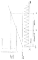
FIG. 9 is a timing chart showing the relationship between the triangular wave and the pulse signal. In FIG. 6A, the upper triangular wave is obtained by adding the value of the dead time register to the lower triangular wave. The counter
同図の(B)はコンペアレジスタの値がデッドタイムレジスタの値よりも小さい場合の各種波形を表している。この場合には、下側の三角波とコンペアレジスタとの値を比較することにより、正相、逆相のパルスが生成される。また、同図の(C)に示されたように、コンペアレジスタの値がカウンタ上限2とカウンタ上限1の間にある場合には、上側の三角波とコンペアレジスタとの値を比較することにより、正相、逆相のパルスが生成される。
(B) in the figure shows various waveforms when the value of the compare register is smaller than the value of the dead time register. In this case, normal-phase and anti-phase pulses are generated by comparing the values of the lower triangular wave and the compare register. Also, as shown in (C) of the figure, when the value of the compare register is between the counter
図10は三角波発生部162によって生成された三角波とレゾルバ31の励磁信号の波形とを表している。本実施形態によれば、励磁信号は三角波に同期したデューティ50%のパルス信号であり、三角波の山と励磁信号のパルスの部分とが一致している。このように、三角波と励磁信号とを同期させることにより、他の信号のA/D変換と同一タイミングでレゾルバ31の検出信号のA/D変換を行うことができる。すなわち、レゾルバ31の検出信号のA/D変換タイミングを他の信号のA/D変換タイミングと一致させることにより、A/D変換のための割り込みを最小限に抑えることができ、システムの安定性を向上させることが可能となる。
FIG. 10 shows the triangular wave generated by the
続いて本実施形態に係るパワーステアリング制御装置の動作を説明する。図11は、パワーステアリング制御装置の動作を表すメインフローチャートである。このフローチャートにおいて、CPU113は、先ず各種タイマおよびレジスタの値を初期値に設定する(ステップS101)。すなわち、ECU1は、PWM基本タイマ161、制御開始タイマ166、A/D開始タイマ167をリセットするとともに、デッドタイムレジスタ164に所望のデッドタイムの値を書き込む。
Next, the operation of the power steering control device according to this embodiment will be described. FIG. 11 is a main flowchart showing the operation of the power steering control device. In this flowchart, the
この後、PWM基本タイマ161がスタートし(ステップS101)、三角波発生部162はタイマの値に基づき三角波を生成する(ステップS103)。比較部163はコンペアレジスタ165に格納されたデューティ比およびデッドタイムレジスタ164に格納されたデッドタイムの値に基づきパルス信号W,V,U,Wb,Vb,Ubを出力する(ステップS104)。モータ駆動回路118はパルス信号W,V,U,Wb,Vb,Ubに基づく駆動電流をモータ3に供給することにより、モータ3によって補助トルクが発生させられる。
Thereafter, the PWM
さらに、CPU113はパワーステアリング装置の故障診断処理を行い、故障が検出された場合には所定のフェールセーフ処理を実行する(ステップS105)。ECU1は、イグニッションキー5aがオフになるまで上述のステップS101〜S105の処理を繰り返し実行することにより、パワーステアリング装置の制御を行う。
Further, the
図12は、A/D変換の割込処理を表すフローチャートである。この割込処理は上述のメインフローチャートにおいてA/D開始タイマ160により割込が発生した場合に実行されるものである。また、図13は、三角波と割込タイマとのタイミングチャートである。A/D変換割込処理を図12,図13を交えながら説明する。
FIG. 12 is a flowchart showing an A / D conversion interrupt process. This interrupt process is executed when an interrupt is generated by the A / D start
先ず、割込タイマは時刻t0において、PWM基本タイマ161、A/D開始タイマ167が同時にスタートする。三角波発生部162はPWM基本タイマ161に基づき50μsec周期の三角波を発生し、A/D開始タイマ167は250μsec周期でアップ、ダウンを繰り返す。すなわち、A/D開始タイマ167が250μsecをカウントすると(時刻t1)、割込コントローラ168は制御処理部160に対して割込を発生させる(時刻t1、ステップS110)。同時に、制御開始タイミングを決定するための制御開始タイマ166がスタートする(ステップS111)。
First, as for the interrupt timer, at time t0, the PWM
割込が発生してから制御処理部160がA/D変換処理を実際に実行するまでには、オーバーヘッド等の要因により所定の遅延時間Δtを要し、制御処理部160は時刻t2においてA/D変換処理を開始する(ステップS113)。A/D変換処理は、予め定められた時間内、すなわち制御開始タイマ168による割込が発生するまで(t2〜t3)に処理を終了しなければ(ステップS114でYES)、異常判定、若しくはA/D変換の強制終了がなされる(ステップS115)。この場合には、A/D変換の対象となっている、トルク信号、モータ駆動電流、モータ端子電圧、レゾルバ検出信号のうち、制御において優先順位の高いものから順にA/D変換を行うことが望ましい。例えば、モータ端子電圧のA/D変換に先立って、モータ駆動電流のA/D変換を行うと良い。全信号についてのA/D変換が終了すると(ステップS116でYES)、処理は図11のメインフローチャートに戻る。
A predetermined delay time Δt is required from the occurrence of the interrupt until the
なお、上述したように、個々の信号のA/D変換に要する時間はデッドタイムdよりも小さいことが望ましい。PWMのパルス信号のデューティ比が0%、100%付近では電圧が安定する時間はデッドタイム程度の短い時間になるので、この時間内にA/D変換を行うことでスイッチングノイズの影響を回避することができる。 As described above, it is desirable that the time required for A / D conversion of individual signals is shorter than the dead time d. When the duty ratio of the PWM pulse signal is 0% and near 100%, the voltage stabilization time is as short as the dead time. Therefore, the influence of switching noise is avoided by performing A / D conversion within this time. be able to.
A/D変換処理の後、制御開始タイマ166による割込が発生すると(時刻t3、ステップS114でYES)、制御処理部160はA/D変換されたトルク信号等に基づき制御演算を開始する。そして、演算結果に基づきコンペアレジスタ165が書き換えられ、所定のパルス幅の信号W,V,U,Wb,Vb,Ubが比較部163から出力される。この結果、モータ3に駆動電流が供給され、補助トルクがステアリングシャフトに印加される。
When an interruption by the
同様に、時刻t1から250μsec経過後に、A/D開始タイマ167による割込が発生し、A/D変換処理、制御処理が実行され、コンペアレジスタ165が書き換えられる。このようにして、250μsec毎にコンペアレジスタ165が書き換えられる。
Similarly, an interrupt by the A / D start
なお、本実施形態においては、上述の割込処理の他に許可された割込処理はパワーオンリセット等の例外的ものだけである。このように、割込処理を限定することにより、無用な割込を最小限に抑えることができる。また、複数の割込を許可する場合には、制御開始タイマによる割込の優先順位を最も高くすることにより、安定した制御を実現することができる。 In the present embodiment, in addition to the above-described interrupt processing, the permitted interrupt processing is only exceptional such as power-on reset. Thus, by limiting the interrupt processing, useless interrupts can be minimized. Further, when a plurality of interrupts are permitted, stable control can be realized by making the priority of interrupts by the control start timer the highest.
以上述べたように、本実施形態によれば、PWMタイマの複数周期毎に、A/D変換、制御処理を実行することにより、割込処理の数を最小限に抑えることができ、制御装置の処理負担を軽減することが可能となる。また、A/D変換をデッドタイム内に実行することにより、スイッチングノイズ等の影響を回避することが可能となる。 As described above, according to the present embodiment, the number of interrupt processes can be minimized by executing A / D conversion and control processing for each of a plurality of periods of the PWM timer. It is possible to reduce the processing load. In addition, by executing A / D conversion within the dead time, it is possible to avoid the influence of switching noise and the like.
(第2実施形態)
図14は本発明の第2実施形態に係るパワーステアリング制御装置のタイミングチャートを表している。本実施形態によれば、A/D開始タイマ167は、PWM基本タイマ161のスタート時刻t1よりも、三角波のA/D変換開始に要する遅延時間Δtだけ早い時刻t0にスタートする。時刻t0から250μsec経過後において、A/D開始タイマ167による割込が発生し(時刻t2)、さらに遅延時間Δt経過後にA/D変換処理が実行される(時刻t3)。すなわち、A/D変換のオーバーヘッド時間を考慮してA/D開始割込時刻を早めることにより、実際のA/D変換開始時刻と三角波の谷の時刻に一致させることができる。
(Second Embodiment)
FIG. 14 shows a timing chart of the power steering control device according to the second embodiment of the present invention. According to the present embodiment, the A / D start
制御開始タイマ166は時刻t2においてスタートした後、時刻t4において割込を発生させる。制御処理部160はA/D変換されたトルク信号、モータ電流等に基づき電流指令値を表すデューティ比を算出し、コンペアレジスタ168に出力する。他の構成については、上述の第1実施形態に係るパワーステアリング制御装置と同様であるので、以下の説明を省略する。
The control start
本実施形態においても、PWMの三角波の複数周期毎にA/D変換、制御処理を実行することにより、割込処理数を最小限に抑えることができる。また、遅延時間Δtを考慮してA/D変換開始割込を発生させることにより、三角波の谷の時刻に正確にA/D変換を実行することが可能となる。 Also in the present embodiment, the number of interrupt processing can be minimized by executing A / D conversion and control processing for each of a plurality of periods of the PWM triangular wave. Further, by generating an A / D conversion start interrupt in consideration of the delay time Δt, it becomes possible to execute A / D conversion accurately at the time of the valley of the triangular wave.
(第3実施形態)
図15は本発明の第3実施形態に係るパワーステアリング制御装置のタイミングチャートを表している。本実施形態においては、フリーランニングタイマとコンペア・マッチ・レジスタとを比較することにより、250μsec周期の割込を発生することが可能である。フリーランニングタイマはPWM基本タイマ161の初期化(時刻t0)から所定の遅延時間Δtだけずれた時刻t1にスタートする。遅延時間Δtは、実際のプログラムを実行させ、システム動作の遅延時間を測定することにより決定される。コンペア・マッチ・レジスタとフリーランニングタイマとが一致した場合には割込が発生し(時刻t2)、A/D変換処理、制御処理が続いて実行される。割込発生と同時に、コンペア・マッチ・レジスタは書き換えられ、さらに250μsec後に割込を発生させる(時刻t3)。他の構成については、第1実施形態と同様であるので、その説明を省略する。
(Third embodiment)
FIG. 15 shows a timing chart of the power steering control device according to the third embodiment of the present invention. In this embodiment, it is possible to generate an interrupt with a period of 250 μsec by comparing the free running timer with the compare match register. The free running timer starts at time t1 which is shifted by a predetermined delay time Δt from initialization (time t0) of the PWM
本実施形態によれば、フリーランニングタイマとコンペア・マッチ・レジスタを用いることにより、PWMの三角波に同期した割込処理を実現することができる。これにより、無用な割込を抑え、装置の処理負担を軽減することが可能となる。 According to the present embodiment, by using a free running timer and a compare match register, it is possible to realize an interrupt process synchronized with a PWM triangular wave. As a result, it is possible to suppress unnecessary interrupts and reduce the processing load on the apparatus.
以上、本実施形態を説明したが、本発明は上述の構成に拘泥されることなく、本発明の趣旨を逸脱しない範囲で変更可能である。例えば、PWMの基本波は三角波に限らず、のこぎり波であっても良い。この場合には、のこぎり波の立ち上がり又は立ち下がりの時刻に同期するようにA/D変換処理、制御処理等の割込を発生させることができる。また、本実施形態に係るパワーステアリング制御装置はコラムタイプ、ラックタイプを問わず、また、油圧式パワーステアリング装置にも適用可能である。さらに、プログラムの形態は上述のフローチャートに限定されず、同様の機能を実現できるものであれば変更可能である。 Although the present embodiment has been described above, the present invention is not limited to the above-described configuration, and can be changed without departing from the spirit of the present invention. For example, the fundamental wave of PWM is not limited to a triangular wave, and may be a sawtooth wave. In this case, interrupts such as A / D conversion processing and control processing can be generated in synchronization with the rising or falling time of the sawtooth wave. Further, the power steering control device according to the present embodiment can be applied to a hydraulic power steering device regardless of a column type or a rack type. Further, the form of the program is not limited to the above-described flowchart, and can be changed as long as the same function can be realized.
1 ECU
3 モータ
4 トルクセンサ
110 A/Dコンバータ
113 CPU
117 PWMコントローラ
118 モータ駆動回路
116 RDコンバータ
160 制御処理部
161 PWM基本タイマ
163 比較部
164 デッドタイムレジスタ
165 コンペアレジスタ
166 制御開始タイマ
167 A/D開始タイマ
168 割込コントローラ
1 ECU
3
117
Claims (43)
前記操舵トルクを表すトルク信号、前記PWM駆動電流を表す信号、前記モータの端子電圧を表す信号の少なくとも一つを読み込む読込手段と、
前記読込手段によって読み込まれた信号に基づき前記目標電流値を算出する制御処理手段とを備え、
前記読込手段および前記制御処理手段は、前記PWM基本波の複数周期毎に処理を実行することを特徴とするパワーステアリング制御装置。 Based on the steering torque applied to the steering, the control target current value of the drive current for driving the motor is calculated, and the pulse width modulated PWM using a predetermined PWM fundamental wave based on the control target current value In a power steering control device that applies drive current to a steering wheel,
Reading means for reading at least one of a torque signal representing the steering torque, a signal representing the PWM drive current, and a signal representing the terminal voltage of the motor;
Control processing means for calculating the target current value based on the signal read by the reading means,
The power steering control device, wherein the reading means and the control processing means execute processing for each of a plurality of periods of the PWM fundamental wave.
前記トルク信号および前記駆動電流信号に基づき制御目標電流値を演算する制御処理部と
前記制御目標電流値に基づき、所定周波数のPWM基本波を用いて正相および逆相のPWMパルス信号を生成するとともに、2つの前記スイッチ素子が同時にオフとなるデッドタイムを前記正相および/または逆相のPWMパルス信号に付加するPWMコントローラと、
前記制御目標値に従いPWMデューティ指令値を演算するデューティ指令値演算部と、
高電位と低電位との間に接続されるとともに、前記PWMパルス信号に基づき相補動作を行うことにより前記駆動電流を生成する2つのスイッチ素子を少なくとも備えた電流駆動回路とを有し、
前記A/Dコンバータは前記デッドタイムに相当する時間内においてA/D変換を実行することを特徴とするパワーステアリング制御装置。 An A / D converter that A / D converts at least one of a torque signal from a torque sensor that detects a steering torque applied to the steering and a drive current signal that represents a drive current to a motor for generating auxiliary torque;
A control processing unit that calculates a control target current value based on the torque signal and the drive current signal, and generates PWM pulses of normal phase and reverse phase using a PWM fundamental wave of a predetermined frequency based on the control target current value And a PWM controller that adds a dead time during which the two switch elements are simultaneously turned off to the positive-phase and / or reverse-phase PWM pulse signals;
A duty command value calculator for calculating a PWM duty command value according to the control target value;
A current drive circuit including at least two switch elements that are connected between a high potential and a low potential and generate the drive current by performing a complementary operation based on the PWM pulse signal;
The power steering control device, wherein the A / D converter performs A / D conversion within a time corresponding to the dead time.
前記操舵トルクを表すトルク信号、前記PWM駆動電流を表す信号、前記モータの端子電圧を表す信号の少なくとも一つをA/D変換し、読み込む読込手段と、
前記読込手段によって読み込まれた信号に基づき前記目標電流値を算出する制御処理手段とを備え、
前記読込手段は前記PWM基本波の周期の1/2以下の時間内においてA/D変換を完了することを特徴とするパワーステアリング制御装置。 Based on the steering torque applied to the steering, the control target current value of the drive current for driving the motor is calculated, and the pulse width modulated PWM using a predetermined PWM fundamental wave based on the control target current value In a power steering control device that applies drive current to a steering wheel,
Reading means for A / D converting and reading at least one of a torque signal representing the steering torque, a signal representing the PWM drive current, and a signal representing the terminal voltage of the motor;
Control processing means for calculating the target current value based on the signal read by the reading means,
The power steering control device according to claim 1, wherein the reading means completes the A / D conversion within a time that is ½ or less of the period of the PWM fundamental wave.
前記操舵トルクを表すトルク信号、前記PWM駆動電流を表す信号、前記モータの端子電圧を表す信号の少なくとも一つを読み込む読込ステップと、
前記読込ステップによって読み込まれた信号に基づき前記目標電流値を算出する制御処理ステップとを備え、
前記読込ステップおよび前記制御処理ステップは、前記PWM基本波の複数周期毎に処理を実行することを特徴とするパワーステアリング制御方法。 A drive current target value for driving the motor is calculated based on the steering torque applied to the steering, and a PWM drive current pulse-modulated using a predetermined PWM fundamental wave is calculated based on the control target current value. In the power steering control method applied to the steering,
A reading step of reading at least one of a torque signal representing the steering torque, a signal representing the PWM drive current, and a signal representing the terminal voltage of the motor;
A control processing step of calculating the target current value based on the signal read by the reading step,
In the power steering control method, the reading step and the control processing step execute processing for each of a plurality of periods of the PWM fundamental wave.
前記トルク信号および前記駆動電流信号に基づき制御目標電流値を演算する制御処理ステップと
前記制御目標電流値に基づき、所定周波数のPWM基本波を用いて正相および逆相のPWMパルス信号を生成するとともに、2つの前記スイッチ素子が同時にオフとなるデッドタイムを前記正相および/または逆相のPWMパルス信号に付加するステップと、
前記制御目標値に従いPWMデューティ指令値を演算するステップと、
高電位と低電位との間に接続されるとともに、前記PWMパルス信号に基づき相補動作を行うことにより前記駆動電流を生成する2つのスイッチ素子を少なくとも備えた電流駆動回路を駆動するステップとを有し、
前記A/Dコンバータは前記デッドタイムに相当する時間内においてA/D変換を実行することを特徴とするパワーステアリング制御方法。 A / D conversion is performed using an A / D converter for at least one of a torque signal from a torque sensor that detects a steering torque applied to the steering and a drive current signal that represents a drive current to a motor for generating auxiliary torque. Steps,
A control processing step of calculating a control target current value based on the torque signal and the drive current signal, and generating a PWM pulse signal of normal phase and reverse phase using a PWM fundamental wave of a predetermined frequency based on the control target current value And adding a dead time during which the two switch elements are simultaneously turned off to the positive-phase and / or reverse-phase PWM pulse signals;
Calculating a PWM duty command value according to the control target value;
And a step of driving a current drive circuit including at least two switch elements that are connected between a high potential and a low potential and generate a drive current by performing a complementary operation based on the PWM pulse signal. And
The power steering control method, wherein the A / D converter performs A / D conversion within a time corresponding to the dead time.
前記操舵トルクを表すトルク信号、前記PWM駆動電流を表す信号、前記モータの端子電圧を表す信号の少なくとも一つをA/D変換し、読み込む読込ステップと、
前記読込ステップによって読み込まれた信号に基づき前記目標電流値を算出する制御処理ステップとを備え、
前記読込ステップは前記PWM基本波の周期の1/2以下の時間内においてA/D変換を完了することを特徴とするパワーステアリング制御方法。 A drive current target value for driving the motor is calculated based on the steering torque applied to the steering, and a PWM drive current pulse-modulated using a predetermined PWM fundamental wave is calculated based on the control target current value. In the power steering control method applied to the steering,
A step of A / D converting and reading at least one of a torque signal representing the steering torque, a signal representing the PWM drive current, and a signal representing the terminal voltage of the motor;
A control processing step of calculating the target current value based on the signal read by the reading step,
The power steering control method according to claim 1, wherein the reading step completes A / D conversion within a time that is ½ or less of a period of the PWM fundamental wave.
前記操舵トルクを表すトルク信号、前記PWM駆動電流を表す信号、前記モータの端子電圧を表す信号の少なくとも一つを読み込む読込ステップと、
前記読込ステップによって読み込まれた信号に基づき前記目標電流値を算出する制御処理ステップとを備え、
前記読込ステップおよび前記制御処理ステップは、前記PWM基本波の複数周期毎に処理を実行することを特徴とするパワーステアリング制御プログラム。 A drive current target value for driving the motor is calculated based on the steering torque applied to the steering, and a PWM drive current pulse-modulated using a predetermined PWM fundamental wave is calculated based on the control target current value. In the power steering control program applied to the steering,
A reading step of reading at least one of a torque signal representing the steering torque, a signal representing the PWM drive current, and a signal representing the terminal voltage of the motor;
A control processing step of calculating the target current value based on the signal read by the reading step,
In the power steering control program, the reading step and the control processing step execute processing for each of a plurality of periods of the PWM fundamental wave.
前記トルク信号および前記駆動電流信号に基づき制御目標電流値を演算する制御処理ステップと
前記制御目標電流値に基づき、所定周波数のPWM基本波を用いて正相および逆相のPWMパルス信号を生成するとともに、2つの前記スイッチ素子が同時にオフとなるデッドタイムを前記正相および/または逆相のPWMパルス信号に付加するステップと、
前記制御目標値に従いPWMデューティ指令値を演算するステップ、
高電位と低電位との間に接続されるとともに、前記PWMパルス信号に基づき相補動作を行うことにより前記駆動電流を生成する2つのスイッチ素子を少なくとも備えた電流駆動回路を駆動するステップとを有し、
前記A/Dコンバータは前記デッドタイムに相当する時間内においてA/D変換を実行することを特徴とするパワーステアリング制御プログラム。 A / D conversion is performed using an A / D converter for at least one of a torque signal from a torque sensor that detects a steering torque applied to the steering and a drive current signal that represents a drive current to a motor for generating auxiliary torque. Steps,
A control processing step of calculating a control target current value based on the torque signal and the drive current signal, and generating a PWM pulse signal of normal phase and reverse phase using a PWM fundamental wave of a predetermined frequency based on the control target current value And adding a dead time during which the two switch elements are simultaneously turned off to the positive-phase and / or reverse-phase PWM pulse signals;
Calculating a PWM duty command value according to the control target value;
And a step of driving a current drive circuit including at least two switch elements that are connected between a high potential and a low potential and generate a drive current by performing a complementary operation based on the PWM pulse signal. And
The power steering control program, wherein the A / D converter executes A / D conversion within a time corresponding to the dead time.
前記操舵トルクを表すトルク信号、前記PWM駆動電流を表す信号、前記モータの端子電圧を表す信号の少なくとも一つをA/D変換し、読み込む読込ステップと、
前記読込ステップによって読み込まれた信号に基づき前記目標電流値を算出する制御処理ステップとを備え、
前記読込ステップは前記PWM基本波の周期の1/2以下の時間内においてA/D変換を完了することを特徴とするパワーステアリング制御プログラム。
A drive current target value for driving the motor is calculated based on the steering torque applied to the steering, and a PWM drive current pulse-modulated using a predetermined PWM fundamental wave is calculated based on the control target current value. In the power steering control program applied to the steering,
A step of A / D converting and reading at least one of a torque signal representing the steering torque, a signal representing the PWM drive current, and a signal representing the terminal voltage of the motor;
A control processing step of calculating the target current value based on the signal read by the reading step,
In the power steering control program, the reading step completes the A / D conversion within a time of ½ or less of the period of the PWM fundamental wave.
Priority Applications (3)
| Application Number | Priority Date | Filing Date | Title |
|---|---|---|---|
| JP2004346726A JP2006158119A (en) | 2004-11-30 | 2004-11-30 | Power steering control device, method and program |
| EP05257379A EP1662647A3 (en) | 2004-11-30 | 2005-11-30 | Power steering control device and power steering control method |
| US11/289,288 US20060113938A1 (en) | 2004-11-30 | 2005-11-30 | Power steering control device and method thereof |
Applications Claiming Priority (1)
| Application Number | Priority Date | Filing Date | Title |
|---|---|---|---|
| JP2004346726A JP2006158119A (en) | 2004-11-30 | 2004-11-30 | Power steering control device, method and program |
Publications (2)
| Publication Number | Publication Date |
|---|---|
| JP2006158119A true JP2006158119A (en) | 2006-06-15 |
| JP2006158119A5 JP2006158119A5 (en) | 2008-01-24 |
Family
ID=35798474
Family Applications (1)
| Application Number | Title | Priority Date | Filing Date |
|---|---|---|---|
| JP2004346726A Pending JP2006158119A (en) | 2004-11-30 | 2004-11-30 | Power steering control device, method and program |
Country Status (3)
| Country | Link |
|---|---|
| US (1) | US20060113938A1 (en) |
| EP (1) | EP1662647A3 (en) |
| JP (1) | JP2006158119A (en) |
Cited By (1)
| Publication number | Priority date | Publication date | Assignee | Title |
|---|---|---|---|---|
| WO2014162561A1 (en) * | 2013-04-04 | 2014-10-09 | 三菱電機株式会社 | Engine automatic stopping/restarting device and engine automatic stopping/restarting method |
Families Citing this family (6)
| Publication number | Priority date | Publication date | Assignee | Title |
|---|---|---|---|---|
| JP4737391B2 (en) * | 2005-06-03 | 2011-07-27 | 株式会社ジェイテクト | Motor drive control method and motor drive control device |
| JP2008193825A (en) * | 2007-02-06 | 2008-08-21 | Matsushita Electric Ind Co Ltd | Ad conversion control circuit and related technology thereof |
| JP5485232B2 (en) * | 2011-07-04 | 2014-05-07 | 本田技研工業株式会社 | Switching circuit control device |
| JP5799899B2 (en) * | 2012-06-27 | 2015-10-28 | 株式会社デンソー | Power converter |
| CN107343389B (en) * | 2015-02-24 | 2020-05-12 | 三菱电机株式会社 | Electric drive device and electric power steering device |
| CN112590916A (en) * | 2020-12-09 | 2021-04-02 | 北京农业智能装备技术研究中心 | Electric steering control system and method for agricultural machinery navigation |
Citations (7)
| Publication number | Priority date | Publication date | Assignee | Title |
|---|---|---|---|---|
| JPH0947065A (en) * | 1995-07-25 | 1997-02-14 | Nissan Motor Co Ltd | Motor drive controller |
| JP2001008482A (en) * | 1999-06-22 | 2001-01-12 | Hitachi Ltd | Control system and control of motor |
| JP2001333591A (en) * | 2000-05-23 | 2001-11-30 | Nissan Motor Co Ltd | Motor drive controller |
| JP2003107112A (en) * | 2001-09-28 | 2003-04-09 | Sharp Corp | Motor current detection device |
| JP2003116295A (en) * | 2001-10-09 | 2003-04-18 | Nissan Motor Co Ltd | Drive controller of motor |
| JP2003267237A (en) * | 2002-03-19 | 2003-09-25 | Honda Motor Co Ltd | Electric power steering device and its control method |
| JP2004304494A (en) * | 2003-03-31 | 2004-10-28 | Fuji Electric Holdings Co Ltd | A/D CONVERTER ADOPTING DeltaSigma MODULATION SYSTEM AND CONTROL APPARATUS EMPLOYING THE SAME |
Family Cites Families (7)
| Publication number | Priority date | Publication date | Assignee | Title |
|---|---|---|---|---|
| JPH0292781A (en) * | 1988-09-28 | 1990-04-03 | Mitsubishi Electric Corp | Motor-driven power steering device |
| JPH0818565B2 (en) * | 1988-12-06 | 1996-02-28 | 株式会社日立製作所 | Current control device, current control method, and electric power steering device |
| US6519571B1 (en) * | 1999-05-27 | 2003-02-11 | Accenture Llp | Dynamic customer profile management |
| US7054823B1 (en) * | 1999-09-10 | 2006-05-30 | Schering Corporation | Clinical trial management system |
| JP3577584B2 (en) * | 2000-05-31 | 2004-10-13 | 光洋精工株式会社 | Electric motor driving device, power steering device, and electric power steering device |
| JP4019825B2 (en) * | 2002-07-09 | 2007-12-12 | 株式会社ジェイテクト | Electric power steering device |
| JP2004161118A (en) * | 2002-11-12 | 2004-06-10 | Koyo Seiko Co Ltd | Power steering device |
-
2004
- 2004-11-30 JP JP2004346726A patent/JP2006158119A/en active Pending
-
2005
- 2005-11-30 US US11/289,288 patent/US20060113938A1/en not_active Abandoned
- 2005-11-30 EP EP05257379A patent/EP1662647A3/en not_active Withdrawn
Patent Citations (7)
| Publication number | Priority date | Publication date | Assignee | Title |
|---|---|---|---|---|
| JPH0947065A (en) * | 1995-07-25 | 1997-02-14 | Nissan Motor Co Ltd | Motor drive controller |
| JP2001008482A (en) * | 1999-06-22 | 2001-01-12 | Hitachi Ltd | Control system and control of motor |
| JP2001333591A (en) * | 2000-05-23 | 2001-11-30 | Nissan Motor Co Ltd | Motor drive controller |
| JP2003107112A (en) * | 2001-09-28 | 2003-04-09 | Sharp Corp | Motor current detection device |
| JP2003116295A (en) * | 2001-10-09 | 2003-04-18 | Nissan Motor Co Ltd | Drive controller of motor |
| JP2003267237A (en) * | 2002-03-19 | 2003-09-25 | Honda Motor Co Ltd | Electric power steering device and its control method |
| JP2004304494A (en) * | 2003-03-31 | 2004-10-28 | Fuji Electric Holdings Co Ltd | A/D CONVERTER ADOPTING DeltaSigma MODULATION SYSTEM AND CONTROL APPARATUS EMPLOYING THE SAME |
Cited By (5)
| Publication number | Priority date | Publication date | Assignee | Title |
|---|---|---|---|---|
| WO2014162561A1 (en) * | 2013-04-04 | 2014-10-09 | 三菱電機株式会社 | Engine automatic stopping/restarting device and engine automatic stopping/restarting method |
| CN105121835A (en) * | 2013-04-04 | 2015-12-02 | 三菱电机株式会社 | Engine automatic stopping/restarting device and engine automatic stopping/restarting method |
| JP5951115B2 (en) * | 2013-04-04 | 2016-07-13 | 三菱電機株式会社 | Engine automatic stop / restart device and engine automatic stop / restart method |
| CN105121835B (en) * | 2013-04-04 | 2017-06-23 | 三菱电机株式会社 | Engine automatic-stop/restasystem system and engine automatic stop restart method |
| US10393084B2 (en) | 2013-04-04 | 2019-08-27 | Mitsubishi Electric Corporation | Engine automatic-stop/restart system and engine automatic-stop/restart method |
Also Published As
| Publication number | Publication date |
|---|---|
| EP1662647A2 (en) | 2006-05-31 |
| EP1662647A3 (en) | 2008-03-26 |
| US20060113938A1 (en) | 2006-06-01 |
Similar Documents
| Publication | Publication Date | Title |
|---|---|---|
| US9362860B2 (en) | Multi-phase motor control apparatus and electric power steering apparatus using the same | |
| JP2007159185A (en) | Electric power steering controller and method | |
| JP5196211B2 (en) | Vehicle steering system | |
| JP5402948B2 (en) | Motor control device and electric power steering device using the same | |
| EP2621080B1 (en) | Motor control device and electric power steering device | |
| JP6662721B2 (en) | Control device, motor control device, and electric power steering device | |
| JP5338969B2 (en) | Power state diagnosis method and apparatus | |
| US20060113938A1 (en) | Power steering control device and method thereof | |
| JP2007152994A (en) | Electric power steering control device and method | |
| JP5831060B2 (en) | Motor control device and vehicle steering device | |
| JP6468461B2 (en) | Motor control device | |
| JP5929521B2 (en) | Motor control device and electric power steering device using the same | |
| JP6136803B2 (en) | Motor control device and electric power steering device using the same | |
| JP2011114883A (en) | Motor control device and electric power steering device using the same | |
| JP6589750B2 (en) | Motor control device | |
| JP2009056820A (en) | Control device of electric power steering device | |
| JP2007159186A (en) | Electric power steering controller and method | |
| JP2009248921A (en) | Electric power steering device | |
| JP4557143B2 (en) | Power steering control device, method, and program | |
| JP6970888B2 (en) | Motor control device | |
| JP2008265645A (en) | Electric power steering device | |
| JP2007069833A (en) | Apparatus and method for controlling electric power steering system | |
| JP2020065328A (en) | Motor control device | |
| JP2020065329A (en) | Motor control device | |
| JP2019047534A (en) | Motor controller |
Legal Events
| Date | Code | Title | Description |
|---|---|---|---|
| A521 | Request for written amendment filed |
Free format text: JAPANESE INTERMEDIATE CODE: A523 Effective date: 20071129 |
|
| A621 | Written request for application examination |
Free format text: JAPANESE INTERMEDIATE CODE: A621 Effective date: 20071129 |
|
| A977 | Report on retrieval |
Free format text: JAPANESE INTERMEDIATE CODE: A971007 Effective date: 20100702 |
|
| A131 | Notification of reasons for refusal |
Free format text: JAPANESE INTERMEDIATE CODE: A131 Effective date: 20100712 |
|
| A02 | Decision of refusal |
Free format text: JAPANESE INTERMEDIATE CODE: A02 Effective date: 20101129 |