JP2006149221A - Filtering device for aquarium and filter material - Google Patents
Filtering device for aquarium and filter material Download PDFInfo
- Publication number
- JP2006149221A JP2006149221A JP2004340555A JP2004340555A JP2006149221A JP 2006149221 A JP2006149221 A JP 2006149221A JP 2004340555 A JP2004340555 A JP 2004340555A JP 2004340555 A JP2004340555 A JP 2004340555A JP 2006149221 A JP2006149221 A JP 2006149221A
- Authority
- JP
- Japan
- Prior art keywords
- water
- filter medium
- filter
- aquarium
- filtration
- Prior art date
- Legal status (The legal status is an assumption and is not a legal conclusion. Google has not performed a legal analysis and makes no representation as to the accuracy of the status listed.)
- Granted
Links
Images


Classifications
-
- Y—GENERAL TAGGING OF NEW TECHNOLOGICAL DEVELOPMENTS; GENERAL TAGGING OF CROSS-SECTIONAL TECHNOLOGIES SPANNING OVER SEVERAL SECTIONS OF THE IPC; TECHNICAL SUBJECTS COVERED BY FORMER USPC CROSS-REFERENCE ART COLLECTIONS [XRACs] AND DIGESTS
- Y02—TECHNOLOGIES OR APPLICATIONS FOR MITIGATION OR ADAPTATION AGAINST CLIMATE CHANGE
- Y02W—CLIMATE CHANGE MITIGATION TECHNOLOGIES RELATED TO WASTEWATER TREATMENT OR WASTE MANAGEMENT
- Y02W10/00—Technologies for wastewater treatment
- Y02W10/10—Biological treatment of water, waste water, or sewage
Landscapes
- Biological Treatment Of Waste Water (AREA)
- Farming Of Fish And Shellfish (AREA)
Abstract
Description
本発明は、観賞魚等の飼育に用いられる水槽内の水を濾過するための濾過装置、及び、この濾過装置に用いる濾材に関する。 The present invention relates to a filtration device for filtering water in an aquarium used for breeding ornamental fish and the like, and a filter medium used in the filtration device.
観賞魚等の飼育に用いられる水槽内の水を濾過する濾過装置としては、水槽の水の中に濾材を設置して濾過を行なう内部濾過式のものと、水槽の外側に濾過装置を設置して濾過を行なう外部濾過式のものがある。特に外部濾過式の濾過装置は、水槽内の有効容積を減じることがなく、また、濾材やその他の部品の交換、清掃が容易であり、メンテナンス性においても利点を有する。 As a filtration device that filters the water in the aquarium used for breeding ornamental fish, etc., an internal filtration type that performs filtration by installing a filter medium in the aquarium water, and a filtration device that is installed outside the aquarium There is an external filtration type that performs filtration. In particular, the external filtration type filtration device does not reduce the effective volume in the water tank, and it is easy to replace and clean the filter medium and other parts, and has an advantage in maintainability.
この外部濾過式の濾過装置の中には、濾過装置を水槽から離れた場所に独立して設置する独立設置型のものと、水槽の周壁等に設置する水槽設置型のものがある。水槽設置型の濾過装置は、水槽と濾過装置の間を接続する長いホースや配管を設置する必要がなく、コンパクトで効率のよい濾過装置を実現可能であり、現在、主に小型の水槽用として広く用いられている。 Among the external filtration type filtration devices, there are an independent installation type in which the filtration device is installed independently in a place away from the water tank, and a water tank installation type in which the filtration device is installed on a peripheral wall of the water tank. The water tank installation type filtration device does not require long hoses and pipes connecting between the water tank and the filtration device, and can realize a compact and efficient filtration device, and is currently mainly used for small water tanks. Widely used.
この水槽設置型の濾過装置は、例えば、濾過装置自体で水槽の周壁を挟み込むようにして周壁の上縁に載せられた形で設置されたものや、フック部材を用いて周壁に設置されたもの等がある。水槽の周壁に設置された濾過装置の濾過器本体の中には、濾材が備えられ、濾過器本体に接続された水ポンプによって、水槽内の不純物や汚れを含む水が汲み上げられて、濾過器本体へ供給される。濾過器本体内へ供給された水は、水の流路の途中に設置された濾材を通過する間に濾過されるようになっている。 This water tank installation type filtration device is, for example, one installed on the upper edge of the peripheral wall so as to sandwich the peripheral wall of the water tank with the filtration device itself, or one installed on the peripheral wall using a hook member Etc. The filter body of the filtration device installed on the peripheral wall of the water tank is equipped with a filter medium, and water containing impurities and dirt in the water tank is pumped up by the water pump connected to the filter body. Supplied to the main body. The water supplied into the filter main body is filtered while passing through a filter medium installed in the middle of the water flow path.
ここでいう濾過としては、水が濾材を通過する間に水に含まれる不純物等を物理的に除去する機械式濾過と、濾材の内部に収納された活性炭等による水の浄化と、濾材中に培養された微生物による生物濾過が含まれる。 As filtration here, mechanical filtration that physically removes impurities contained in water while water passes through the filter medium, purification of water by activated carbon stored in the filter medium, and in the filter medium Biofiltration by cultured microorganisms is included.
また、濾過された水は、例えば、濾過器本体からオーバーフローすることによって、再び水槽へ戻る。濾過器本体から水槽へ戻るときには、通常、濾過器本体の排水側にスロープ状の排水口が設けられており、濾過された水は、この排水口の上を流れ落ちて水槽の水面に注ぎ込まれる。以上のような工程を繰り返すことによって水槽内の水を濾過し、また、水が排水口上を流れ落ちる間に、水と大気とを接触させて、大気中の酸素を水の中に取り込み、水槽内の水に酸素を供給するようになっている。 Moreover, the filtered water returns to a water tank again, for example by overflowing from a filter main body. When returning from the main body of the filter to the water tank, a slope-shaped water outlet is normally provided on the drain side of the main body of the filter, and the filtered water flows down on this water outlet and is poured into the water surface of the water tank. By repeating the above steps, the water in the aquarium is filtered, and while the water flows down on the drain outlet, the water is brought into contact with the atmosphere, oxygen in the atmosphere is taken into the water, It is designed to supply oxygen to the water.
この水槽設置型の濾過装置の中には、例えば、加圧によって水が濾材を通過するようにして、濾材の広い領域を有効に活用し、濾過の効率を向上させ、濾材の耐用寿命を向上させる提案がなされている(例えば、特許文献1参照)。また、その他の提案として、サイフォンの作用による吸引力で水が濾材を通過するようにして、濾過の効率を向上させ、濾過装置のメンテナンス頻度を減らす提案もなされている(例えば、特許文献2参照)。
上述の特許文献1及び特許文献2に記載された濾過装置においては、濾過の効率や濾材のメンテナンス性を向上させる提案がなされているが、濾過された水は、いずれも従来の水槽設置型の濾過装置と同様に、おおむね平滑な表面を有するスロープ状の排水口の上を流れ落ちて、水槽の水面に注ぎ込まれるようになっている。ここで、従来型の排水口の一例を、図7(b)に示す。図7(b)に示すように、濾過された水が流れ落ちていく排水口5の表面形状は、平滑な平面または曲面で構成されている。
In the filtration devices described in
上述のように、濾過器本体は水槽の周壁に設置されるが、このとき、排水口が完全に水平になるように設置することは困難である。また、水槽自体も完全に水平に設置することは困難である。従って、重力により排水口の上を流れ落ちる水は、排水口の流路領域全体に均等に流れることは稀であり、通常、設置された排水口の微妙な傾斜によって、高さが低い方の端に集中して流れ落ちることになる。そして、一箇所に集まって流れた水は、そのまま、水槽の水面の一箇所へ集中して注ぎ込まれる。 As described above, the filter body is installed on the peripheral wall of the water tank. At this time, it is difficult to install the filter body so that the drain outlet is completely horizontal. Moreover, it is difficult to install the water tank itself completely horizontally. Therefore, the water that flows down the drainage port due to gravity rarely flows evenly over the entire drainage channel area, and is usually at the lower end due to the subtle inclination of the installed drainage port. Concentrate on and flow down. And the water which gathered and flowed to one place concentrates and is poured into one place of the water surface of a water tank as it is.
図7(b)に示す実施例においては、排水口5は、紙面の左側が右側よりも若干高くなっており、水は矢印に示すように右下に流れ、排水口5の流路領域のうち右端に集中して流れ落ち、水槽の水面の一箇所に集中して注ぎ込まれる。
このように、濾過された水が排水口の上の一箇所に集中して流れ、水槽の水面の一箇所に集中して注ぎ込まれるので、戻る水が水面と衝突するときの衝撃は大きなものになる。この衝撃は、繊細な観賞魚に大きなストレスを与えることになり、鑑賞魚を飼育する上で大きな問題となる。
In the embodiment shown in FIG. 7 (b), the
In this way, the filtered water flows in one spot on the drain and concentrates and is poured in one spot on the water surface of the aquarium, so the impact when the returning water collides with the water surface is large. Become. This impact gives great stress to delicate ornamental fish, and becomes a big problem in breeding appreciation fish.
また、上述のように、排水口の上を水が流れ落ちる間に大気中の酸素を取り込んで、水槽内の水に酸素を供給することは、この水槽設置型の濾過装置の重要な働きの1つであるが、上述の一箇所に集中した流れの場合には、排水口の流路領域全体に均一に流れる場合と比べて、大気との接触面積が小さくなる。従って、流れ落ちる水に大気中の酸素を取り込むことがあまりできず、水槽内の水に十分な酸素を供給することができないという問題も生じる。 In addition, as described above, taking oxygen in the atmosphere while water flows down on the drain outlet and supplying oxygen to the water in the aquarium is one of the important functions of this aquarium installation type filtration device. However, in the case of the flow concentrated in one place described above, the contact area with the atmosphere is smaller than in the case where the flow flows uniformly over the entire flow path region of the drain port. Therefore, there is a problem that oxygen in the atmosphere cannot be taken into the flowing water so much that sufficient oxygen cannot be supplied to the water in the water tank.
この排水口の上で一箇所に集中して流れる現象は、特に流れ落ちる水の量が少ない場合に顕著である。従って、濾過する水の循環量が少ない小型の水槽において、特に大きな問題となる。また、排水口の傾きだけでなく、排水口の流路領域に油や汚れ等が付くことによって、一箇所に集中した水の流れが生じる恐れもある。 This phenomenon of concentrated flow at one location on the drain outlet is particularly noticeable when the amount of water flowing down is small. Therefore, it becomes a big problem especially in a small water tank with a small amount of circulating water to be filtered. Further, not only the inclination of the drain port but also oil or dirt on the channel region of the drain port may cause a concentrated water flow in one place.
更に、上述のように、濾材による濾過の重要な働きとして、濾材の中に微生物を繁殖させて、この微生物により水を浄化する生物濾過がある。しかし、特許文献1及び特許文献2に記載された濾過装置においては、水中の不純物等を物理的に除去する機械的濾過の効率を向上することについては提案がなされているが、濾材が水中に没していて大気と触れることはないので、生物濾過に重要な役割を果たす好気性微生物の繁殖速度は遅く、微生物の分解活動も活発にならない場合がある。また、嫌気性微生物による生物濾過も考えられるが、この嫌気性微生物の繁殖についても、特許文献1及び特許文献2に記載された濾材においては、栄養源に乏しく、十分な繁殖は期待できないことが考えられる。従って、特許文献1及び特許文献2に記載された濾材においては、微生物による生物濾過が十分に行なわれないという問題が生じることが考えられる。
Furthermore, as described above, an important function of filtration by a filter medium is biological filtration in which microorganisms are propagated in the filter medium and water is purified by the microorganisms. However, in the filtering devices described in
従って、本発明の目的は、上述の課題を解決し、水槽の周壁に設置された濾過装置において、濾過された水が、水槽の水面の一箇所に集中して注ぎ込まれて観賞魚にストレスを与えることを防止し、注ぎ込まれる水に大気中の酸素を取り入れて、水槽の水に十分な酸素を供給でき、更に、好気性微生物や嫌気性微生物による生物濾過を十分に行なうことのできる濾過装置、及び濾材を提供することにある。 Accordingly, the object of the present invention is to solve the above-mentioned problems, and in the filtration device installed on the peripheral wall of the aquarium, the filtered water is concentrated and poured into one place on the water surface of the aquarium and stresses the ornamental fish. A filtration device that prevents supply of oxygen and can supply sufficient oxygen to the water in the aquarium by incorporating oxygen in the water into the water to be poured, and can sufficiently perform biological filtration with aerobic and anaerobic microorganisms. And providing a filter medium.
上述の目的を達成するため、本発明の水槽用濾過装置の第1の実施態様として、水槽の周壁に設置されて前記水槽内の水を濾過する濾過装置であって、1または2以上の濾材(第1の濾材)と、前記濾材(第1の濾材)を通過して濾過された水を前記水槽へ戻すための排水口と、を有する濾過器本体と、前記水槽内の水を前記濾過器本体へ供給するための水ポンプと、を含み、前記排水口に、水が一定方向に流れるようにガイドされた複数の水路が備えられている濾過装置が考えられる。 In order to achieve the above object, as a first embodiment of the water tank filtration device of the present invention, a filtration device installed on the peripheral wall of the water tank to filter the water in the water tank, comprising one or more filter media (First filter medium), a filter body having a drain outlet for returning water filtered through the filter medium (first filter medium) to the water tank, and filtering the water in the water tank And a water pump for supplying water to the vessel main body, and a drainage port provided with a plurality of water channels guided so that water flows in a certain direction is conceivable.
本実施態様では、濾過装置を水槽に設置する方法として、あらゆる方法をとることができる。例えば、濾過装置自体が水槽の周壁を挟み込むようにして、水槽の周壁の上縁へ載せられる形で設置されることも考えられるし、フック状の部材を用いて周壁に引っ掛けることも考えられるし、ネジや吸盤等を用いて周壁に取り付けることも考えられる。また、その他様々な方法が考えられる。 In this embodiment, all methods can be taken as a method of installing the filtration device in the water tank. For example, the filtering device itself may be placed on the upper edge of the peripheral wall of the water tank so as to sandwich the peripheral wall of the water tank, or it may be hooked on the peripheral wall using a hook-shaped member. It is also possible to attach to the peripheral wall using screws, suction cups or the like. Various other methods are also conceivable.
濾過器本体の設置位置は、水槽の周壁に対して外側に設置する場合も、水槽の周壁に対して内側に設置する場合も考えられる。
濾過された水は、濾過器本体からオーバーフローによって排水口側へ流出させることも考えられるし、所定の圧力を掛けて流出させることも考えられるし、水ポンプ等によって流出させることも考えられる。また、その他様々な方法が考えられる。
The installation position of the filter main body may be installed outside the peripheral wall of the water tank or may be installed inside the peripheral wall of the water tank.
It is conceivable that the filtered water flows out from the main body of the filter to the drain outlet side by overflow, may flow out by applying a predetermined pressure, or may flow out by a water pump or the like. Various other methods are also conceivable.
濾過器本体や排水口の材質としては、所定の強度を有し、水槽内の水に悪影響を与えないものであれば、合成樹脂を始めとするあらゆる材料を用いることができる。また、水ポンプは、電動ポンプを始めとするあらゆる動力を用いたポンプを用いることができる。
この水ポンプの吸水口については、直接、水槽内の水面に接して水を汲み上げることもできるし、配管やホース等を接続して水槽の水を汲み上げることもできる。また、濾過装置の破損や水路の詰まりを防ぐため、水槽の水に含まれるゴミ等を除去するためのストレーナを吸込口に設置することも考えられる。また、水ポンプの吐出口は、直接、濾過器本体に接続してもよいし、配管やホース等を介して濾過器本体へ接続してもよい。更に、水を供給する経路の途中に、流量を調整するための流量調整弁を設置することもできる。
As a material of the filter main body and the drain, any material including a synthetic resin can be used as long as it has a predetermined strength and does not adversely affect the water in the water tank. Moreover, the pump using all the motive powers including an electric pump can be used for a water pump.
With respect to the water inlet of this water pump, water can be pumped directly in contact with the water surface in the water tank, or water in the water tank can be pumped up by connecting pipes or hoses. In addition, in order to prevent damage to the filtration device and clogging of the water channel, it is also conceivable to install a strainer for removing dust contained in the water in the water tank at the suction port. Moreover, the discharge port of the water pump may be directly connected to the filter main body, or may be connected to the filter main body via a pipe or a hose. Furthermore, a flow rate adjusting valve for adjusting the flow rate can be installed in the middle of the path for supplying water.
濾材(第1の濾材)としては、あらゆる種類の濾材を用いることが可能であり、例えば、合成樹脂性の繊維からなるものや、その内部に活性炭等を含むものも考えられる。濾材(第1の濾材)による濾過としては、水が通過する間に水に含まれる不純物等を物理的に除去する機械式濾過と、濾材の内部に活性炭等を収納している場合には、その活性炭等による水の浄化が考えられる。
更に、濾材中に培養した好気性微生物によって、例えば、水の中の不純物や汚れから生じたアンモニアを亜硝酸に分解し、更に、比較的無害な硝酸塩に分解する水の浄化が考えられる。ただし、好気性微生物による水の浄化に関しては、濾材が水中に没して大気に触れない状態にある場合には、微生物の培養速度は遅く、微生物の分解活動が活発にならない場合があることも考えられる。
As the filter medium (first filter medium), any type of filter medium can be used. For example, a filter medium made of synthetic resin or an active carbon inside thereof can be considered. As filtration by the filter medium (first filter medium), mechanical filtration that physically removes impurities contained in water while water passes, and when activated carbon or the like is stored inside the filter medium, Water purification using activated carbon or the like can be considered.
Furthermore, it is conceivable to purify water by aerobic microorganisms cultured in the filter medium, for example, by decomposing ammonia generated from impurities or dirt in water into nitrous acid and further decomposing into relatively harmless nitrates. However, regarding the purification of water by aerobic microorganisms, if the filter medium is submerged in water and is not in contact with the air, the culture rate of the microorganisms may be slow and the microbial decomposition activity may not be active. Conceivable.
水槽から導かれた水について濾材(第1の濾材)を通過させる方法としては、水を所定量溜めて、溜まった水のヘッドによって通過させることも考えられるし、所定の圧力を加えて通過させることも考えられるし、水ポンプ等を用いて通過させることも考えられる。また、濾材の出側を負圧にして通過させることも考えられるし、その他様々な方法を採用することができる。 As a method of passing the filter medium (first filter medium) through the water guided from the water tank, it is conceivable to store a predetermined amount of water and pass it through the head of the accumulated water, or to pass it by applying a predetermined pressure. It is conceivable that the water is passed through using a water pump or the like. Further, it is conceivable to let the outlet side of the filter medium pass under a negative pressure, and various other methods can be adopted.
水が一定方向に流れるようにガイドされた水路については、あらゆる種類の水路を採用することが可能であり、例えば、溝を切って水路を設けることもできるし、水路と水路の間に側壁を立てて水路を設けることもできる。また、水路の断面形状についても、あらゆる断面形状をとることができる。水路の流れ方向としては、重力により水が流れ落ちる方向に一致させることが効率がよいと考えられるが、状況に応じて、任意の方向をとることができる。 As for the water channel guided so that the water flows in a certain direction, all kinds of water channels can be adopted, for example, a water channel can be provided by cutting a groove, and a side wall is provided between the water channel and the water channel. A water channel can also be provided upright. Moreover, all cross-sectional shapes can be taken also about the cross-sectional shape of a water channel. As the flow direction of the water channel, it is considered efficient to match the direction in which water flows down due to gravity, but it can take any direction depending on the situation.
従来の水槽の周壁に設置された濾過装置においては、濾過された水が水槽へ戻るときに通過する排水口を完全に水平にするように、濾過装置を設置することは不可能であり、特に、水の循環量の少ない小型の水槽では、排水口の微妙な傾きによって、水が排水口の1箇所に集まって流れ落ち、水槽の水面の一箇所に集中して注ぎ込まれる恐れが高い。
このため、繊細な観賞魚にストレスを与える問題が生じ、また、水が一箇所に集まって流れるため、大気との接触面積が減少して、十分な大気中の酸素が取り込めないという問題も生じる。
In the filtration device installed on the peripheral wall of the conventional aquarium, it is impossible to install the filtration device so that the drain outlet through which the filtered water returns to the aquarium is completely horizontal, especially In a small aquarium with a small amount of water circulation, there is a high possibility that water will collect and flow down at one location of the drainage port and be concentrated and poured into one location on the water surface of the aquarium due to the slight inclination of the drainage port.
For this reason, the problem which gives stress to a delicate ornamental fish arises, and since water gathers and flows in one place, the contact area with the atmosphere decreases and the problem that sufficient oxygen in the atmosphere cannot be taken up also arises. .
しかし、本実施態様によれば、設置された排水口に多少傾きが生じていても、濾過された水は、ガイドされた各水路中を流れるので、排水口の流路領域全体を均一に流れて水槽の水面に注ぎ込まれる。従って、水が注ぎ込まれるときの衝撃で、観賞魚に余分なストレスを与える恐れが少なく、また、大気との接触面積も大きく取れるので、流れる水に大気中の酸素を十分取り込め、水槽内の水に十分な酸素を供給することができる。 However, according to the present embodiment, even if the installed drainage port is slightly inclined, the filtered water flows through each guided water channel, so that it flows uniformly in the entire channel region of the drainage port. Poured into the surface of the tank. Therefore, there is little risk of giving extra stress to the ornamental fish due to the impact when water is poured, and the contact area with the atmosphere can be increased, so that enough oxygen in the atmosphere can be taken into the flowing water, and the water in the aquarium Sufficient oxygen can be supplied.
本発明の水槽用濾過装置のその他の実施態様として、前記水路が、概略V字形状または概略U字形状の断面を有する濾過装置が考えられる。
本実施態様によれば、水が確実に一定方向へ流れるようにすることが可能であり、また、水路も容易に形成することが可能で、排水口の製造コストを低減することもできる。
As another embodiment of the water tank filtering device of the present invention, a filtering device in which the water channel has a substantially V-shaped or U-shaped cross section is conceivable.
According to this embodiment, it is possible to ensure that water flows in a certain direction, and it is possible to easily form a water channel, and to reduce the manufacturing cost of the drain.
本発明の水槽用濾過装置のその他の実施態様として、前記水路の流路に、突起または凹凸を有する濾過装置が考えられる。
本実施態様によれば、水路中を流れる水が、突起や凹凸によって攪拌されるため、更に、大気との接触を増やして、より多くの酸素を水の中に取り込むことができる。なお、突起や凹凸の大きさ、設置位置、設置個数等については、あらゆる大きさ、あらゆる設置位置、あらゆる設置個数を採用することができる。また、この凹凸には、凹凸の高さが非常に低い、水路の表面を荒らした状態も含まれる。
As another embodiment of the water tank filtering device of the present invention, a filtering device having protrusions or irregularities in the channel of the water channel is conceivable.
According to this embodiment, since the water flowing in the water channel is agitated by the protrusions and irregularities, the contact with the atmosphere can be further increased, and more oxygen can be taken into the water. In addition, about the magnitude | size of a protrusion and an unevenness | corrugation, an installation position, installation number, etc., all sizes, all installation positions, and all installation numbers can be employ | adopted. In addition, the unevenness includes a state in which the surface of the water channel is rough, where the height of the unevenness is very low.
本発明の水槽用濾過装置のその他の実施態様として、前記水路に、生物濾過を行なうことができる第2の濾材が備えられている濾過装置が考えられる。
ここで、第2の濾材としては、あらゆる種類の濾過材を用いることが可能であり、例えば、合成樹脂性の繊維からなるものが考えられる。本実施態様においては、第2の濾材が排水口の水路に設置されるため、排水口を流れ落ちる水の多くがこの第2の濾材の中を通り、また、第2の濾材は大気とも十分触れることができるので、生物濾過を行なうための好気性微生物の培養を促進させ、その微生物の分解活動を活性化させるのに適している。従って、濾材(第1の濾材)では十分行なうことができなかった水の生物濾過に関して、第2の濾材によって十分に行なうことが期待できる。
As another embodiment of the water tank filtration device of the present invention, a filtration device in which a second filter medium capable of biological filtration is provided in the water channel is conceivable.
Here, as the second filter medium, any type of filter medium can be used, and, for example, one made of synthetic resinous fibers can be considered. In the present embodiment, since the second filter medium is installed in the drainage channel, most of the water flowing down the drainage port passes through the second filter medium, and the second filter medium is sufficiently in contact with the atmosphere. Therefore, it is suitable for promoting the culture of aerobic microorganisms for performing biofiltration and activating the degradation activity of the microorganisms. Therefore, it can be expected that the second filter medium will be sufficient for biofiltration of water that could not be sufficiently performed with the filter medium (first filter medium).
本発明の水槽用濾過装置のその他の実施態様として、前記第2の濾材が、前記水路の断面に対応した断面形状を有する紐状の濾材である濾過装置が考えられる。
本実施態様によれば、第2の濾材が、排水口の水路の断面に対応した断面形状を有するので、水路を流れる水を十分に含み、かつ、大気とも十分に触れることができる生物濾過に最適な環境を設定できるので、水槽の水の浄化を最大限を行なうことが期待できる。
As another embodiment of the water tank filtering device of the present invention, a filtering device in which the second filter medium is a string-shaped filter medium having a cross-sectional shape corresponding to the cross section of the water channel is conceivable.
According to the present embodiment, since the second filter medium has a cross-sectional shape corresponding to the cross section of the water channel of the drain outlet, the second filter medium sufficiently contains water flowing through the water channel and can be sufficiently exposed to the atmosphere. Since the optimal environment can be set, it can be expected to maximize the purification of water in the aquarium.
本発明の水槽用濾過装置のその他の実施態様として、前記第2の濾材が、着脱可能な状態で前記濾材(第1の濾材)に取り付けられる濾過装置が考えられる。
本実施態様においては、第2の濾材を濾材(第1の濾材)に取り付けることによって、水路等に接着したりすることなく、第2の濾材を排水口の水路の適切な位置に設置することができ、また、第2の濾材と濾材(第1の濾材)を分離することも可能なので、濾材の交換等を個別に自由に行なうことができる。
As another embodiment of the water tank filtration device of the present invention, a filtration device in which the second filter medium is attached to the filter medium (first filter medium) in a detachable state is conceivable.
In this embodiment, by attaching the second filter medium to the filter medium (first filter medium), the second filter medium is installed at an appropriate position in the water channel of the drain outlet without adhering to the water channel or the like. In addition, since the second filter medium and the filter medium (first filter medium) can be separated, the filter medium can be exchanged individually and freely.
本発明の水槽用濾過装置のその他の実施態様として、前記第2の濾材が、内部に生分解性プラスチックを含む濾過装置が考えられる。ここで、生分解性プラスチックとは、主に穀物でんぷんを主成分としたプラスチックであり、微生物によって分解される特徴をもつプラスチックである。 As another embodiment of the water tank filtering device of the present invention, a filtering device in which the second filter medium contains a biodegradable plastic inside is conceivable. Here, the biodegradable plastic is a plastic mainly composed of cereal starch, and is a plastic having characteristics of being degraded by microorganisms.
本実施態様の生分解性プラスチックを内部に含む第2の濾材においては、上述のアンモニアを亜硝酸、硝酸塩に分解する好気性微生物(硝化細菌)だけでなく、水槽の水の中の不純物や汚れに含まれる有機窒素をアンモニアに分解する好気性微生物(従属栄養細菌)や、硝酸塩を窒素ガスに分解する嫌気性微生物(脱窒細菌)を始めとする微生物も、速やかに繁殖させることができる。従って、水槽の水を浄化して、PHを始めとする水質を安定させることが可能であり、長期間、水槽の水の交換を行なわないで観賞魚等の飼育が可能になる。 In the second filter medium containing the biodegradable plastic in the present embodiment, not only the above-mentioned aerobic microorganisms (nitrifying bacteria) that decompose ammonia into nitrite and nitrate, but also impurities and dirt in the water in the aquarium. Microorganisms such as aerobic microorganisms (heterotrophic bacteria) that decompose organic nitrogen contained in water into ammonia and anaerobic microorganisms (denitrifying bacteria) that decompose nitrate into nitrogen gas can be rapidly propagated. Accordingly, it is possible to purify the water in the aquarium and stabilize the water quality including PH, and it is possible to breed ornamental fish and the like without exchanging the water in the aquarium for a long period of time.
本発明の水槽用濾過装置のその他の実施態様として、粒子状の前記生分解性プラスチックが、互いに接触しないように、前記第2の濾材中に含まれている濾過装置が考えられる。
本実施態様によれば、生分解性プラスチックを粒子状にすることによって、プラスチックの表面積を大きくして、速やかに微生物を繁殖させることができる。また、生分解性プラスチックの粒子どうしが、互いに接触しないようにすることによって、生分解性プラスチックどうしが反応して溶解し、水槽の水を白濁させたりすることを防ぐことができる。
As another embodiment of the water tank filtration device of the present invention, a filtration device in which the particulate biodegradable plastic is contained in the second filter medium so as not to contact each other is conceivable.
According to this embodiment, by making the biodegradable plastic into particles, the surface area of the plastic can be increased and microorganisms can be propagated quickly. Further, by preventing the biodegradable plastic particles from coming into contact with each other, it is possible to prevent the biodegradable plastic from reacting and dissolving and causing the water in the water tank to become clouded.
本発明の水槽用濾過装置の取り扱い方法の第1の実施態様として、前記濾材(第1の濾材)と前記第2の濾材を異なる時期に交換して、前記濾材(第1の濾材)または前記第2の濾材の少なくとも一方に生物濾過のための微生物が保たれるようにする濾過装置の濾材の交換方法が考えられる。
水中に没している濾材のみ(第1の濾材に対応する濾材)が設置された従来の濾過装置においては、濾材を交換すると、それまで培養されていた微生物を全て失うことになり、新たな濾材で微生物が培養されるまで、水の生物濾過が行なわれない状態となる。しかし、本実施態様によれば、何れかの濾材に微生物を保つことができるので、常に、水の生物濾過を行なうことができ、濾材の交換による生物濾過の影響を最小限にとどめることができる。
As a first embodiment of the method for handling the water tank filtration device of the present invention, the filter medium (first filter medium) and the second filter medium are exchanged at different times, and the filter medium (first filter medium) or It is conceivable to replace the filter medium of the filter device so that microorganisms for biological filtration are retained in at least one of the second filter medium.
In the conventional filtration apparatus in which only the filter medium submerged in water (the filter medium corresponding to the first filter medium) is installed, if the filter medium is replaced, all microorganisms that have been cultured until then will be lost, and Until the microorganisms are cultured on the filter medium, the biological filtration of water is not performed. However, according to this embodiment, since microorganisms can be kept in any one of the filter media, it is possible to always perform biological filtration of water, and to minimize the influence of biological filtration due to replacement of the filter media. .
本発明の濾過装置用濾材の第1の実施態様として、生物濾過を行なうことができる濾材であって、繊維状の濾材の中に、生分解性プラスチックが含まれている濾過装置用濾材が考えられる。
本実施態様の生物濾材においては、上述と同様に、水槽の水の中の不純物や汚れに含まれる有機窒素をアンモニアに分解する好気性微生物(従属栄養細菌)、アンモニアを亜硝酸、硝酸塩に分解する好気性微生物(硝化細菌)、硝酸塩を窒素ガスに分解する嫌気性微生物(脱窒細菌)を始めとする細菌を、速やかに繁殖させることによって、水槽の水を浄化して、PHを始めとする水質を安定させることが可能であり、長期間、水槽の水の交換を行なわないで、観賞魚等の飼育が可能になる。
As a first embodiment of the filter medium for a filter according to the present invention, a filter medium capable of performing biological filtration, which is a filter medium for a filter that contains a biodegradable plastic in a fibrous filter medium, is considered. It is done.
In the biological filter medium of this embodiment, as described above, aerobic microorganisms (heterotrophic bacteria) that decompose organic nitrogen contained in impurities and dirt in the aquarium water into ammonia, and ammonia is decomposed into nitrous acid and nitrates. By rapidly breeding bacteria, including aerobic microorganisms (nitrifying bacteria) and anaerobic microorganisms (denitrifying bacteria) that decompose nitrate into nitrogen gas, the water in the aquarium is purified and PH is started. It is possible to stabilize the quality of the water to be used, and it is possible to breed ornamental fish and the like without exchanging the water in the aquarium for a long period of time.
この生物濾材の形状としては、紐状のものには限られず、シート状、マット状を始めとするあらゆる形状をとることができる。また、生物濾材の設置場所としては、排水口上には限られず、水槽の水と大気に触れることのできる場所であれば、濾過装置の吸水路を始めとして、あらゆる場所に設置することができる。 The shape of the biological filter medium is not limited to a string shape, and can take any shape including a sheet shape and a mat shape. Moreover, the installation place of the biological filter medium is not limited to the drain outlet, and can be installed in any place including the water absorption path of the filtration device as long as it can come into contact with water and air in the water tank.
本発明の生物濾材のその他の実施態様として、粒子状の前記生分解性プラスチックが、互いに接触しないように、繊維状の濾材の中に含まれている濾過装置用濾材が考えられる。
本実施態様によれば、上述と同様に、生分解性プラスチックを粒子状にすることによって、プラスチックの表面積を大きくして、速やかに微生物を繁殖させることができる。また、生分解性プラスチックの粒子どうしが、互いに接触しないようにすることによって、生分解性プラスチックが反応して溶解し、水槽の水を白濁させたりすることを防ぐことができる。
As another embodiment of the biological filter medium of the present invention, a filter medium for a filter device, which is contained in a fibrous filter medium so that the particulate biodegradable plastics do not come into contact with each other, can be considered.
According to this embodiment, similarly to the above, by making the biodegradable plastic particles, the surface area of the plastic can be increased and microorganisms can be propagated quickly. Further, by preventing the biodegradable plastic particles from coming into contact with each other, it is possible to prevent the biodegradable plastic from reacting and dissolving and causing the water in the water tank to become clouded.
本発明の水槽用濾過装置によれば、排水口に水路を備えることにより、濾過された水が、排水口の流路領域全体を均一に流れて水槽の水面に注ぎ込まれるので、水が注ぎ込まれるときに生じる衝撃を和らげて、観賞魚に大きなストレスを与える恐れを減少させ、また、排水口を流れる水と大気との接触面積も大きく取ることによって、水槽内の水に大気中の酸素を十分に供給することができる。 According to the water tank filtration device of the present invention, by providing a water channel at the drain port, the filtered water flows uniformly through the entire channel region of the drain port and is poured into the water surface of the water tank, so that water is poured. Reduces the risk of stressing the ornamental fish by mitigating the shocks that occur from time to time, and also increases the contact area between the water flowing through the drain and the atmosphere, so that enough oxygen in the atmosphere is contained in the water in the tank. Can be supplied to.
また、第2の濾材を排水口の水路に備えることによって、濾材(第1の濾材)では十分行なうことができなかった水の生物濾過を、第2の濾材によって十分に行なうことができる。 In addition, by providing the second filter medium in the water channel of the drain outlet, biological filtration of water that could not be sufficiently performed by the filter medium (first filter medium) can be sufficiently performed by the second filter medium.
更に、第2の濾材の内部に生分解性プラスチックを含むことによって、水槽の水を浄化して、PHを始めとする水質を安定させることが可能であり、長期間、水槽の水の交換を行なわないで、観賞魚等の飼育が可能になる。 Furthermore, by containing a biodegradable plastic inside the second filter medium, it is possible to purify the water in the aquarium and stabilize the water quality including PH, and to replace the water in the aquarium for a long period of time. Without performing it, it is possible to breed ornamental fish.
本発明の水槽用濾過装置の実施形態について、以下に図面を用いながら詳細に説明する。 Embodiments of the water tank filtration device of the present invention will be described in detail below with reference to the drawings.
(濾過装置の全体構造の説明)
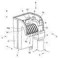
始めに、本発明の水槽用濾過装置の1つの実施形態に関して、図1を参照しながら、全体構造を説明する。図1には、濾過装置1の1つの実施形態の斜視図を示す。なお、濾過装置1では上部に蓋を取り付けることができるが、図1では蓋は取り外した状態が示されている。また、図1に示す矢印は、水の流れを示している。
(Description of the overall structure of the filtration device)
First, regarding one embodiment of the water tank filtration device of the present invention, the overall structure will be described with reference to FIG. FIG. 1 shows a perspective view of one embodiment of a
本実施形態においては、第1の濾材4を内部に備えた濾過器本体2と、濾過された水がその上を流れ落ちて水槽へ注ぎ込まれる排水口5とは、一体に成型されている。また排水口5には、概略V字形状の断面を有する6本の水路5aが設けられ、各々の水路5aには紐状の生物濾材である第2の濾材6が備えられている。また、紙面において排水口5の右隣には、電動モータで駆動される水ポンプ3が、濾過器本体2や排水口5と一体に成型された吸水部12に接続されている。水ポンプ3の下側には、水槽内の水の吸い込み口となるストレーナ7が接続されている。
In the present embodiment, the filter
吸水部12の上方には、吸水管8が接続され、水槽内の水を濾過器本体2の内部へ導くようになっている。給水管8には、濾過器本体2へ導く水の流量を調整するための流量調整弁15が設置されている。なお、濾過器本体2と排水口5、及び、濾過器本体2と吸水部12の間で形成されるフック部14に、水槽の周壁(図示されていない)の上部が差し込まれ、フック部14の受け部14aと水槽の上縁が接触して、濾過装置1が水槽の周壁の上縁へ載せられた形で水槽に取り付けられる。このとき、位置調整部材16によって、濾過装置1の水槽に対する位置(傾き)を調整することができる。
本実施形態では、濾過器本体2が水槽の外側に位置し、排水口5や水ポンプ3が水槽の内側へ位置している。そして、水ポンプ3(全部または一部)やストレーナ7は、水槽の水の中に入っており、排水口5の下端(つまり、水の注ぎ口)は、水面よりも若干上方へ位置している。
A
In this embodiment, the filter
図1に示す矢印を用いて水の流れを簡略に説明すると、まず、水ポンプ3の吸引力により、水槽の水の中に位置するストレーナ7から、水槽中の水を吸い込む。このストレーナ7により、水中の大きなゴミ等は除去され、水ポンプ3が破損したり給水管8が詰まったりすることを防いでいる。ストレーナ7から吸い込まれた水は、水ポンプ3を通過して、吸水部12内の水路(図示せず)を上昇して吸水管8へ入り、矢印に示されるように、進行方向を180度変えて、濾過器本体2内の吸水室(図示せず)に入る。給水管8には、流量調整弁15が設置されており、所望の流量に調整することができる。
The flow of water will be briefly described using the arrows shown in FIG. 1. First, the water in the water tank is sucked from the
吸水室に入った水は、吸水室に貯められた水のヘッドにより、第1の濾材4を通過して濾過され、濾過器本体2内の排水室(図示せず)へ入る。第1の濾材4による濾過は、主に水の汚れや不純物等を物理的に除去する機械式濾過が主であるが、濾材の内部に含まれた活性炭による水の浄化や、好気性微生物による生物濾過も行なわれる。そして、排水室に入った水は、オーバーフローして排水口5を流れ落ちて、矢印に示すように水槽へ注ぎ込まれる。
The water that has entered the water absorption chamber is filtered by the head of water stored in the water absorption chamber through the
排水路5には、概略V字形状の断面を有する水路5aが6本設けられ、濾過された水が排水口5の流路領域全体に均一に流れ落ちるようになっている。また、各々の水路5aには、第2の濾材6が備えられており、水路5aを流れ落ちる間に生物濾過により、水が浄化されるようになっている。
The
図2には、図1に示す濾過装置1の分解斜視図を示す。水ポンプ3の吸水口に接続されるストレーナは、メイン部材7aとその周囲を覆うスポンジ7bから構成される。水ポンプ3は電動モータで駆動され、電源を供給するためのコード3dが取り付けられている。また、濾過器本体2や排水口5と一体に成型された吸水部12は、上下に水路が明けられており、入側(下側)には水ポンプ3の吐出口が接続され、出側(上側)には給水管8が接続される。給水管8は、第1部材8aと第2部材8bが接続されてU字型の水路を形成し、第1部材8aの上部には、流量調整弁15が取り付けられる。この流量調整弁15は、上部のつまみを持って回転させて、下部の仕切り板の角度を調整することによって、水の流量を調整することができる。
FIG. 2 shows an exploded perspective view of the
本実施形態では、第1の濾材4(濾材本体4a)の上部と第2の濾材6の上部は、同じ押さえ板4bで押さえられ、押さえ板4bの上からクリップ4cによって固定されている。従って、組み立て時には、第1の濾材4と第2の濾材6は上部で接合された形となり、クリップ4cをはずせば、容易に分離できるようになっている
In the present embodiment, the upper part of the first filter medium 4 (filter
また、濾過器本体2の両側2箇所に切り欠き13が上下に切られており、この切り欠き13に、第1の濾材4(濾材本体4a)の両端を差し込むことによって、第1の濾材4を、濾過器本体2の内部に固定することができる。同様に、上部が第1の濾材4に取り付けられた紐状の第2の濾材6を、接着等をすることなく、排水路5の各々の水路5aにセットすることができる。
以上のように、第1の濾過材4と第2の濾過材6を装着した後、蓋11を濾過器本体2の上部に載せて濾過装置1の準備が完了する。
Moreover, the
As described above, after mounting the
図1に示す濾過装置の構造を示すその他の参考図面を、図3〜図5に示す。図3には、図1の斜視図の矢印Aから見た立面図を示し、図4には、図1の斜視図の矢印Bから見た平面図を示し、図5には、図1の斜視図の矢印Cから見た立面図を示す。各図に示す矢印は、水の流れを示す。 Other reference drawings showing the structure of the filtration device shown in FIG. 1 are shown in FIGS. 3 shows an elevational view as seen from the arrow A in the perspective view of FIG. 1, FIG. 4 shows a plan view as seen from the arrow B in the perspective view of FIG. 1, and FIG. The elevation view seen from arrow C of this perspective view is shown. The arrows shown in each figure indicate the flow of water.
(濾過装置の詳細な構造と水の流れの説明)
次に、図6に示す断面図を参照しながら、図1に示す濾過装置1に関する更に詳細な構造説明と、更に詳細な水の流れの説明を行なう。図6は、図1の斜視図の矢印Cの方向から見た断面図であるが、水の流れをわかりやすく示すために模式的に表わしている。水の流れを矢印で示す。
(Detailed structure of filtration device and explanation of water flow)
Next, with reference to the cross-sectional view shown in FIG. 6, a more detailed structural description regarding the
水槽の周壁20の上縁に濾過装置1の受け部14aが接する形で、濾過装置1が周壁20上に設置され、濾過器本体2は水槽の外側に位置している。なお、位置調整部材16によって、濾過装置1が適切な位置で取り付けられるようになっている。この位置調整部材16は、プレート16aとプレート16aに偏芯して取り付けられた回転軸16bからなり、この回転軸16bを介して濾過器本体2の底部に取り付けられている。濾過装置1を水槽の周壁に取り付けたときに、プレート16aが周壁の外壁と接触する。回転軸16bが偏芯して取り付けられているので、プレート16bを回転させることによって、濾過装置1の取り付け位置(傾き)を適切に調整することができる。
The
水槽内の水が、濾過装置1に入って濾過され、再び水槽へ戻るまでの水の流れを説明する。水ポンプ3の吸引力により、水槽内の水がストレーナ7から吸い込まれる。ストレーナ7は、メイン部材7aとその外側を覆うスポンジ7bからなり、スポンジ7bによって、水中の大きなゴミが除去され、濾過装置1内に進入することを防いでいる。メイン部材7aは開口穴が明けられており、水槽の水が流入して水ポンプ3へ入る。水ポンプ7は、ケーシング7cの中に防水処理が施された電動モータ3aが取り付けられ、電動モータ3aの駆動軸にはインペラ3bが取り付けられている。電動モータ3aの駆動力によりインペラ3bが回転して、水槽内の水が吸引され濾過器本体2の方へ導かれる。
The flow of water until the water in the water tank enters the
吸引された水は、更に、吸水部(図示せず)の水路12a、吸水管8を通過して、濾過器本体2の吸水室9へ入る。吸水管8に設けられた流量調整弁15によって、水ポンプ7により導かれる水の流量を、所望の流量に調整することができ、濾過器本体2内の水面は、一点差線で示されるような状態で保たれる。この吸水室9に貯められた水のヘッドによって、水槽から導かれた水は、矢印に示すように、第1の濾材4を通過して濾過される。
The sucked water further passes through the
この第1の濾材4は、樹脂製の繊維からなり、水が樹脂製の繊維の間を通過する間に、不純物等が物理的に除去される機械式濾過が行なわれる。また、第1の濾材4の内部には活性炭が充填されており、水を浄化する機能も有する。更に、大きな表面積を有する樹脂性の繊維の中に好気性微生物を繁殖させて、この微生物により、水の中の不純物や汚れから生じるアンモニアを亜硝酸を経て、比較的無害な硝酸塩へ分解して、水を浄化する生物濾過を行なうこともできる。ただし、第1の濾材4は水中に没しているので、好気性微生物の繁殖速度は遅く、微生物による分解活動も活発に行なわれない場合もあるので、後述するように、排水口5に第2の濾材6を備えて、十分な生物濾過が行なわれるようにしている。なお、本実施形態では、第1の濾材4と、第2の濾材6の上部が共に押さえ板4bで挟み込まれ、クリップ4cによって固定されている。
The
第1の濾材4を通過した水は排水室10へ入り、排水室10に溜まった水は、オーバーフローして排出口5の水路5aを流れ落ちて、水槽へ注ぎ込まれる。水路5aを流れ落ちるときには、水の多くは、紐状の第2の濾材6の中を通過し、その間に生物濾過が十分に行なわれる。この排水口5上の水の流れ、及び、第2の濾材6における生物濾過については、下記に詳述する。
The water that has passed through the
(排出口の説明)
図7(a)に本発明に係る排水口5を有する濾過装置1の実施例を示し、図7(b)には、従来型の排水口を有する濾過装置の実施例を示す。どちらも、図1に示す斜視図の矢印Aの方向から見た立面図であるが模式的に示している。なお、排水口5上の水の流れを明らかにするため、図7(a)に示す濾過装置1には、第2の濾材5は示されていない。
どちらの濾過装置も水槽の周壁に設置されているが、排水口5が完全に水平になるように周壁に取り付けることは困難であり、また、水槽自体も完全に水平に設置することは困難である。本実施例では、どちらの濾過装置の取り付け状態も、紙面における左側が右側よりも若干高い状態で設置されている。
(Description of outlet)
FIG. 7 (a) shows an embodiment of the
Although both filtration devices are installed on the peripheral wall of the aquarium, it is difficult to attach the
濾過された水は、オーバーフローして排水口5上を流れ落ちて水槽へ注ぎ込まれるが、図7(b)に示す従来型の排水口5では、流路領域は、比較的滑らかな平面または曲面で構成されているため、流れ落ちる水は重力の影響により、矢印に示すように全て右下の方向へ流れる。従って、排水口5の流路領域の右端に全ての水が集まって流れ、水槽の一箇所に集中して注ぎ込まれる。このとき、注ぎ込まれる水が水面に衝突するときの衝撃は大きく、繊細な観賞用魚に大きなストレスを与える問題が生じる。
The filtered water overflows and flows down on the
更に、排水口5の流路領域の一箇所に集中して水が流れるので、大気との接触面積が非常に小さくなるため、流れ落ちる水に大気中の酸素を取り込むことが十分にできない。循環する水に十分な酸素を取り込んで、水槽内の水に十分な酸素を供給することは、水槽設置型の濾過装置の重要な働きの1つであるが、この働きを十分に果たすことはできない。
特に、小型の水槽の場合には、循環する水量が少ないため、水が一箇所に集中して流れ落ちる傾向が顕著に現れるため、特に問題となる。また、小型の水槽で飼育される鑑賞魚は、一般的に小型魚の場合が多いので、より深刻な問題を引き起こす恐れがある。
Furthermore, since water flows in one place in the flow path region of the
In particular, in the case of a small water tank, since the amount of water to circulate is small, the tendency of water to concentrate and flow down in one place appears so that it becomes a particular problem. In addition, appreciation fish bred in small aquariums are generally small fishes and may cause more serious problems.
一方、図7(a)に示す本発明に係る排水口5を有する濾過装置1では、排水口5の流路領域全体に、概略V字形状の断面を有する6本の水路5aが設けられており、濾過された水は、この水路5aに沿って流れるので、流路領域全体に均等に水が流れ落ちて、水槽の一箇所に集中して注ぎ込まれることはない。従って、観賞魚に大きなストレスを与える恐れが少ない。循環する水量の少ない小型の水槽であっても、水槽の一箇所に集中して注ぎ込まれる恐れはない。
また、水は流路領域全体に均等に流れるので、大気との接触面積を大きく取ることが可能であり、流れ落ちる水に十分な酸素を取り込むことができ、水槽内の水に十分な酸素を供給することができる。
On the other hand, in the
In addition, since the water flows evenly over the entire flow path area, it is possible to increase the contact area with the atmosphere, and sufficient oxygen can be taken into the flowing water, and sufficient oxygen is supplied to the water in the aquarium. can do.
以上のように、本発明に係る排水口5を用いれば、水が排水口5の幅方向全体に均等に注ぎ込まれるので、観賞魚によけいなストレスを与える恐れが少なく、また、水槽内の水に十分な酸素を供給することができる。なお、本発明に係る排水口5に設けられる水路の断面形状は、V字型には限られず、U字型を始めとするあらゆる断面形状を採用することができる。
As described above, when the
(第2の濾材の説明)
次に、図8を参照しながら、本発明に係る第2の濾材の1つの実施形態に関して、詳細な説明を行なう。図8は、排水口5に設けられた水路5aの断面を模式的に現した図である。概略V字型形状の断面を有する水路5aの中に、概略円形状の断面を有する紐状の第2の濾材6が備えられている。図8は、第1の濾材4を通過して濾過された後、排水室10に溜まった水がオーバーフローして、この水路5aの中を流れ落ちるときの断面を示している。
(Explanation of the second filter medium)
Next, with reference to FIG. 8, a detailed description will be given regarding one embodiment of the second filter medium according to the present invention. FIG. 8 is a diagram schematically showing a cross section of the
この実施形態では、第2の濾材5は樹脂製の繊維からなり、上部を除く領域は流れ落ちる水に浸かった状態におかれ、上部は空気中に出た状態になっている。従って、全てが水中に没している第1の濾材4に比べて、好気性微生物の繁殖を促し、この好気性微生物が分解活動を行なうのに、非常に適した環境が設定されている。
図8の矢印に示すように、第2の濾材6の中で培養されている好気性微生物は、上側から大気中の酸素を取り込んで、水中の不純物や汚れから生じるアンモニアを、亜硝酸を経て、比較的無害な硝酸塩に分解する生物濾過を行なう。第2の濾材6は、好気性微生物の分解活動に適した環境下にあるため、第1の濾材4で十分に行なうことのできなかった水の浄化を十分行なうことができる。
In this embodiment, the
As shown by the arrows in FIG. 8, the aerobic microorganisms cultured in the
本実施形態の第2の濾材6の断面形状は概略円形であるが、排水口5の各水路の断面形状に応じて所望の形状をとることができる。どのような断面形状の水路5aであっても、排水口5の各水路5aを流れ落ちる水の多くが、第2の濾材6の中を流れるようにし、かつ、第2の濾材6の上部は大気に接するようにすることによって、最適な生物濾過を行なうことができる。
Although the cross-sectional shape of the
また、第1の濾材と第2の濾材の交換方法であるが、上述のように、両者は容易に分離することができるので、両者の交換時期をずらして交換することによって、常に、どちらかの濾材の中に、微生物が保たれるようにすることができる。このことによって、常に、生物濾過による水の浄化が可能となり、濾材交換による影響を最小限にとどめることができる。 Moreover, although it is the replacement | exchange method of a 1st filter medium and a 2nd filter medium, since both can be isolate | separated easily as mentioned above, it is always either by changing both exchange time and exchanging. It is possible to keep microorganisms in the filter medium. As a result, the water can always be purified by biological filtration, and the influence of the filter medium exchange can be minimized.
(その他の実施形態)
以上のように本発明の濾過装置の実施形態を説明してきたが、本発明の濾過装置は上述の実施形態には限られず、例えば、下記のような実施形態も考えられる。
(Other embodiments)
As mentioned above, although the embodiment of the filtration device of the present invention has been described, the filtration device of the present invention is not limited to the above-described embodiment, and for example, the following embodiment is also conceivable.
<排水口のその他の実施形態>
図9に本発明に係る排水口5のその他の実施形態を示す。この実施形態においては、水が一定方向に流れるようにガイドされた水路5aに、水の流れを攪拌するための突起または凹凸が設けられている。図9(a)に示す実施形態では、水路5aの入側、中央部、出側に突起が設けられており、図9(b)には、水路5aの全長に凹凸が設けられている。
これらの突起や凹凸により水の流れを攪拌することによって、水と大気との接触面積を増やして、より多くの大気中の酸素を水の中に取り込むことができるようにしている。この突起や凹凸の、大きさ、設置位置、設置個数等については、この実施形態には限られず、あらゆる大きさ、設置位置、設置個数が考えられる。また、この凹凸には、凹凸の高さが非常に低い水路の表面を荒らした状態のものも含まれる。
<Other embodiments of drain port>
FIG. 9 shows another embodiment of the
By agitating the flow of water with these protrusions and irregularities, the contact area between the water and the atmosphere is increased, so that more oxygen in the atmosphere can be taken into the water. The size, installation position, number of installations, and the like of the protrusions and irregularities are not limited to this embodiment, and any size, installation position, and number of installations can be considered. In addition, the unevenness includes a state in which the surface of the water channel having a very low unevenness is roughened.
<第2の濾材のその他の実施形態1>
上述の第2の濾材6の実施形態では、樹脂製の繊維からなる紐状の濾材が用いられているが、第2の濾材のその他の実施形態として、この紐状の濾材の内部に生分解性プラスチックを備えた濾材が考えられる。ここで、生分解性プラスチックは、主に穀物でんぷんを主成分としたプラスチックであり、微生物によって分解される特徴をもつプラスチックである。
<
In the embodiment of the
図10は、生分解性プラスチックが内部に含まれる第2の濾材6が、概略V字形状の断面を有する水路5aに設置されたところを示す断面図である。また、この断面図には、第2の濾材6内の各微生物の働きも示してある。図10に示すように、概略円形状の断面を有する紐状の第2の濾材6の内部に、生分解性プラスチック18が備えられている。生分解性プラスチック18は、図示されているように粒子状になっており、この粒子状の生分解性プラスチック18を覆う濾材6aは、本実施形態では、上述の濾材と同様に樹脂製の繊維から構成されている。
FIG. 10 is a cross-sectional view showing that the
生分解性プラスチック18を含有した紐状の第2の濾材6は上側が大気に接しており、大気中の酸素を吸収し易い状態にある。従って、生分解性プラスチック18を栄養源として活動する好気性微生物(従属栄養細菌)Aが、図10に示すように、生分解性プラスチック18の周りに繁殖する。この好気性微生物(従属栄養細菌)Aは、生分解性プラスチックと酸素を取り込んで、水槽の水に含まれる不純物(例えば、餌の食べ残しや糞等)や汚れから生じる有機窒素を、アンモニアに分解する働きをする。なお、有機窒素をアンモニアに分解する好気性微生物(従属栄養細菌)Aは、水槽中にも自然に繁殖するが、その繁殖速度は遅く、活動も活発とはいえない。一方、生分解性プラスチック18を用いた場合には、非常に早く繁殖し、多くの有機窒素をアンモニアに分解することができる。
The upper side of the string-like
生分解性プラスチック18の周りに繁殖した好気性微生物(従属栄養細菌)Aは酸素を消費し、第2の濾材6内に酸素の少ない嫌気的環境を生成する。そして、この嫌気的環境下の領域に、生分解性プラスチック18を栄養源とする嫌気性微生物(脱窒細菌)Bが繁殖する。この嫌気性微生物(脱窒細菌)Bは、生分解性プラスチックを取り込んで、水の中の硝酸塩を窒素ガスに分解して、大気中へ放出する働きをする。
The aerobic microorganism (heterotrophic bacterium) A propagated around the
また、図10に示すように、好気性微生物(従属栄養細菌)Aや嫌気性微生物(脱窒細菌)Bが繁殖した領域の周りに、上述の生分解性プラスチック18を含まない第2の濾材6と同様に、大気中の酸素を取り込んで好気性微生物(硝化細菌)Cが繁殖する。この好気性微生物(硝化細菌)Cは、上述と同様に、水の中のアンモニアを、亜硝酸、硝酸塩に分解する働きをする。 In addition, as shown in FIG. 10, the second filter medium does not contain the above-described biodegradable plastic 18 around the area where aerobic microorganisms (heterotrophic bacteria) A and anaerobic microorganisms (denitrifying bacteria) B propagated. Similar to 6, aerobic microorganisms (nitrifying bacteria) C propagate by taking in oxygen in the atmosphere. This aerobic microorganism (nitrifying bacterium) C functions to decompose ammonia in water into nitrite and nitrate, as described above.
なお、粒子状の生分解性プラスチック18が樹脂製の繊維の中に含有されているが、これは、生分解性プラスチック18どうしが直接接触すると、互いに反応して溶解し、水槽の水を白く濁らす原因にもなるので、濾材6aの繊維によって、生分解性プラスチック18の各粒子が直接接触するのを防止するためである。
In addition, although the particulate
次に、図11に示す模式図を用いて、これらの微生物による水槽の水の浄化のサイクルを説明する。まず、きれいな水が水槽に入れられ、観賞魚が飼育される(ステップS1)。そして、餌の食べ残しや糞等の不純物や汚れから生じる有機窒素が、水槽の水の中に生じる(ステップS2)。この水槽の水の中に生じた有機窒素は、好気性微生物(従属栄養細菌)Aによって、アンモニアに分解される(ステップS3)。この好気性微生物(従属栄養細菌)Aは、水槽の中の水にも自然に発生するが、本実施形態の第2の濾材6に比べると、大気中から取り込む酸素量も少なく栄養源も乏しいので、その繁殖速度は遅い。従って、水槽の水に含まれる有機窒素は、主に、第2の濾材6を通過するとき、その中に繁殖した好気性微生物(従属栄養細菌)Aによって、アンモニアに分解される。
Next, the cycle of water purification in the aquarium by these microorganisms will be described using the schematic diagram shown in FIG. First, clean water is put in an aquarium, and ornamental fish are bred (step S1). And organic nitrogen which arises from impurities and dirt, such as uneaten bait and feces, arises in the water of an aquarium (Step S2). The organic nitrogen generated in the water in the tank is decomposed into ammonia by the aerobic microorganism (heterotrophic bacteria) A (step S3). This aerobic microorganism (heterotrophic bacterium) A naturally occurs in the water in the aquarium, but compared with the
次に、好気性微生物(従属栄養細菌)Aによって分解されて生じたアンモニアが、好気性微生物(硝化細菌)Cによって、亜硝酸へ分解され(ステップS4)、更に、硝酸塩へ分解される(ステップS5)。この好気性微生物(硝化細菌)Cは、上述のように、主に機械式濾過を行なう第1の濾材でも繁殖するが、大気と接する第2の濾材6と比べれば繁殖速度も遅く、分解活動も活発ではない。従って、水の中のアンモニアは、主に、第2の濾材6を通過するとき、第2の濾材6中に繁殖した好気性微生物(硝化細菌)Cによって、硝酸塩に分解される。
Next, ammonia generated by being decomposed by the aerobic microorganism (heterotrophic bacteria) A is decomposed into nitrous acid by the aerobic microorganism (nitrifying bacteria) C (step S4), and further decomposed into nitrate (step). S5). As described above, the aerobic microorganism (nitrifying bacterium) C propagates even in the first filter medium that mainly performs mechanical filtration. However, the aerobic microorganism (nitrifying bacteria) C has a slower propagation speed than the
次に、好気性微生物(硝化細菌)Cによって分解されて生じた硝酸塩が、嫌気性微生物(脱窒細菌)Bによって、窒素ガスに分解され大気中へ放出される(ステップS6)。従来、水槽の中で硝酸塩を分解することは困難であったが、水の中の硝酸塩は、第2の濾材6を通過するとき、第2の濾材6中に繁殖した嫌気性微生物(脱窒細菌)Bによって、窒素ガスに分解され大気に放出される。
Next, nitrate produced by decomposition by aerobic microorganisms (nitrifying bacteria) C is decomposed into nitrogen gas by anaerobic microorganisms (denitrifying bacteria) B and released into the atmosphere (step S6). Conventionally, it has been difficult to decompose nitrate in a water tank, but when nitrate in water passes through the
以上のサイクルによって、餌の食べ残しや観賞魚の糞の不純物や汚れから生じる有機窒素が、最終的には窒素ガスとして大気に放出され、再びきれいな水となって元のサイクルに戻る。従って、この生分解性プラスチック18を内部に含む第2の濾材6を用いることによって、長期間、水槽の水替えを行なわないで、観賞魚等の飼育が可能になる。
Through the above cycle, organic nitrogen resulting from uneaten food and impurities and dirt of ornamental fish feces is finally released into the atmosphere as nitrogen gas, and returns to the original cycle as clean water. Therefore, by using the
また、好気性微生物(硝化細菌)Cによるアンモニアを亜硝酸、硝酸塩へ分解する硝化工程(ステップS4、5参照)で、PHを減少させる水素イオンが発生するが、嫌気性微生物(脱窒細菌)Bによる硝酸塩を窒素ガスに分解する脱窒工程(ステップS6参照)で、水素イオンが消費され、また、PHを増加させる水酸イオンが発生するので、常に水のPHを安定させることができる。従来は、嫌気性微生物(脱窒細菌)Bによる脱窒工程が活発に行われないため、濾過装置を用いて濾過を続けると、水のPHが徐々に下がり、観賞魚が餌を食べなくなって衰弱するといった問題が生じていたが、この生分解性プラスチック18を内部に含む第2の濾材6によって、PHの低下を防止して、安定した水質を保つことができる。下記に、この硝化工程と脱窒工程の化学式を示す。
Further, in the nitrification step (see Steps S4 and S5) in which ammonia by aerobic microorganisms (nitrifying bacteria) C is decomposed into nitrous acid and nitrates, hydrogen ions that reduce PH are generated, but anaerobic microorganisms (denitrifying bacteria) In the denitrification step (see step S6) in which the nitrate by B is decomposed into nitrogen gas, hydrogen ions are consumed, and hydroxide ions that increase PH are generated, so that the pH of water can always be stabilized. Conventionally, the denitrification process by anaerobic microorganisms (denitrifying bacteria) B is not performed actively. Therefore, if filtration is continued using a filtration device, the pH of water gradually decreases, and ornamental fish no longer eat food. Although the problem of weakening has occurred, the
硝化工程
NH+ 4 + 3/2O2 → NO− 2+H2O+2H+
NO− 2 + 1/2O2 → NO− 3
脱窒工程
2NO− 3 + 10H+ → N2+4H2O+2OH−
2NO− 2 + 6H+ → N2+2H2O+2OH−
Nitrification process NH + 4 + 3/2 O 2 → NO - 2 + H 2 O + 2H +
NO - 2 + 1 / 2O 2 → NO - 3
Denitrification process 2NO - 3 + 10H + → N 2 + 4H 2 O + 2OH −
2NO − 2 + 6H + → N 2 + 2H 2 O + 2OH −
また、この生分解性プラスチック18を含む第2の濾材6では、栄養源となる生分解性プラスチックが存在し、また、大気から十分な酸素を取り入れることができるので、好気性微生物(従属栄養細菌)Aが速やかに繁殖し、この好気性微生物(従属栄養細菌)Aによって、嫌気的環境が形成されて、嫌気性微生物(脱窒細菌)Bも速やかに繁殖する。また、大気から十分な酸素を取り入れることができる環境にあるため、好気性微生物(硝化細菌)Cも速やかに繁殖する。従って、観賞魚に飼育開始後、速やかに上述の微生物を繁殖させて、水の浄化を行ない、PHは含む水の安定化を図ることができる。特に、生分解性プラスチック18を粒子状にすることによって、プラスチックの表面積を大きくし、飼育開始直後の早い時期に微生物を繁殖させるようにできる。
Further, in the
<第2の濾材のその他の実施形態2>
上述の第2の濾材6の実施形態では、各々の水路の断面に対応した断面形状を有する紐状の生物濾材が用いられているが、排水口5の流路領域全体をカバーする一体型の生物濾材を用いることも考えられる。この生物濾材は、例えば、図12(a)に示すようなシート状またはマット状の形状のものも考えられ、循環する水量がある程度以上あって、水が排水口5の流路領域全体に流れることが想定できる場合等に用いることができる。
<
In the embodiment of the
<第2の濾材のその他の実施形態3>
上述の生分解性プラスチック18を含む第2の濾材6においても、各々の水路の断面に対応した断面形状を有する紐状の形状の生物濾材だけでなく、排水口5の流路領域全体をカバーする一体型の生物濾材を用いることも考えられる。図12(b)には、一例として、合成樹脂の繊維から構成されるシート状またはマット状の濾材の中に、生分解性プラスチック18が含まれた実施形態の断面図を示す。なお、この断面図は、水の流れに対して垂直方向に切った断面である。
<
In the
<第2の濾材のその他の実施形態4>
上述の第2の濾材の説明では、濾過装置1の排水口5に設置した実施形態を示しているが、設置場所は排水口5には限られず、循環する水や大気に触れることのできる場所であれば、濾過装置の吸水側を始めとするあらゆる場所に設置することが可能である。また、設置する第2の濾材の形状も、紐状やシート状、マット状に限られず、その水路の形状に合わせて、あらゆる形状が考えられる。
例えば、図6に示す濾過装置1では、吸水管8によって水槽の水が濾過器本体2へ導かれるが、吸水管8の代わりに大気に解放された水路を設けて、その上に第2の濾材を設置することも可能である。
<
In the description of the second filter medium described above, the embodiment is shown in which the
For example, in the
更に、本発明の水槽用濾過装置は、上述の実施形態には限られず、その他様々な実施形態が含まれる。 Furthermore, the water tank filtration device of the present invention is not limited to the above-described embodiment, and includes various other embodiments.
1 濾過装置
2 濾過器本体
3 水ポンプ
3a 電動モータ
3b インペラ
3c ケーシング
3d コード
4 第1の濾材
4a 濾材本体
4b 押さえ板
4c クリップ
5 排水口
6 第2の濾材
6a 濾材
7 ストレーナ
7a メイン部材
7b スポンジ
8 吸水管
8a 第1部材
8b 第2部材
9 吸水室
10 排水室
11 蓋
12 吸水部
12a 水路
13 切り欠き
14 フック部
14a 受け部
15 流量調整弁
16 位置調整部材
16a プレート
16b 回転軸
18 生分解性プラスチック
20 水槽の周壁
DESCRIPTION OF
Claims (11)
1または2以上の濾材と、前記濾材を通過して濾過された水を前記水槽へ戻すための排水口と、を有する濾過器本体と、
前記水槽内の水を前記濾過器本体へ供給するための水ポンプと、
を含み、
前記排水口に、水が一定方向に流れるようにガイドされた複数の水路が備えられていることを特徴とする濾過装置。 A filtration device installed on the peripheral wall of the aquarium to filter the water in the aquarium,
A filter body having one or more filter media, and a drain for returning water filtered through the filter media to the water tank,
A water pump for supplying water in the water tank to the filter body;
Including
A filtration device, wherein the drain port is provided with a plurality of water channels guided so that water flows in a certain direction.
Priority Applications (1)
| Application Number | Priority Date | Filing Date | Title |
|---|---|---|---|
| JP2004340555A JP4318630B2 (en) | 2004-11-25 | 2004-11-25 | Water tank filtration device and filter medium |
Applications Claiming Priority (1)
| Application Number | Priority Date | Filing Date | Title |
|---|---|---|---|
| JP2004340555A JP4318630B2 (en) | 2004-11-25 | 2004-11-25 | Water tank filtration device and filter medium |
Publications (2)
| Publication Number | Publication Date |
|---|---|
| JP2006149221A true JP2006149221A (en) | 2006-06-15 |
| JP4318630B2 JP4318630B2 (en) | 2009-08-26 |
Family
ID=36628232
Family Applications (1)
| Application Number | Title | Priority Date | Filing Date |
|---|---|---|---|
| JP2004340555A Active JP4318630B2 (en) | 2004-11-25 | 2004-11-25 | Water tank filtration device and filter medium |
Country Status (1)
| Country | Link |
|---|---|
| JP (1) | JP4318630B2 (en) |
Cited By (4)
| Publication number | Priority date | Publication date | Assignee | Title |
|---|---|---|---|---|
| US7594998B2 (en) | 2006-04-13 | 2009-09-29 | Newa Tecno Industria S.R.L. | Aquarium filter assembly and filter element |
| JP2012143706A (en) * | 2011-01-12 | 2012-08-02 | Central Research Institute Of Electric Power Industry | Electron donor supplying apparatus and denitrification bioreactor |
| WO2019112044A1 (en) | 2017-12-07 | 2019-06-13 | 三菱ケミカル株式会社 | Purification method for water, purification device for water, and use of said purification device at low water temperature |
| WO2020004635A1 (en) | 2018-06-29 | 2020-01-02 | 三菱ケミカル株式会社 | Water purification device, aquaculture water purification system, water purification method, and production method for aquatic organism |
-
2004
- 2004-11-25 JP JP2004340555A patent/JP4318630B2/en active Active
Cited By (8)
| Publication number | Priority date | Publication date | Assignee | Title |
|---|---|---|---|---|
| US7594998B2 (en) | 2006-04-13 | 2009-09-29 | Newa Tecno Industria S.R.L. | Aquarium filter assembly and filter element |
| US7601259B2 (en) * | 2006-04-13 | 2009-10-13 | Newa Tecno Industria S.R.L. | Aquarium filter |
| US7618534B2 (en) | 2006-04-13 | 2009-11-17 | Newa Tecno Industria S.R.L. | Aquarium filter |
| US7771592B2 (en) | 2006-04-13 | 2010-08-10 | Newa Tecno Industria S.R.L. | Aquarium filter |
| JP2012143706A (en) * | 2011-01-12 | 2012-08-02 | Central Research Institute Of Electric Power Industry | Electron donor supplying apparatus and denitrification bioreactor |
| WO2019112044A1 (en) | 2017-12-07 | 2019-06-13 | 三菱ケミカル株式会社 | Purification method for water, purification device for water, and use of said purification device at low water temperature |
| US11185059B2 (en) | 2017-12-07 | 2021-11-30 | Mitsubishi Chemical Corporation | Purification method for water, purification device for water, and use of said purification device at low water temperature |
| WO2020004635A1 (en) | 2018-06-29 | 2020-01-02 | 三菱ケミカル株式会社 | Water purification device, aquaculture water purification system, water purification method, and production method for aquatic organism |
Also Published As
| Publication number | Publication date |
|---|---|
| JP4318630B2 (en) | 2009-08-26 |
Similar Documents
| Publication | Publication Date | Title |
|---|---|---|
| US7604734B2 (en) | Water filtration system | |
| US5176824A (en) | Aerobic aquarium filter chamber | |
| JP3553950B2 (en) | Aerobic aquarium filtration chamber | |
| KR20150001800U (en) | For Aquarium Floating Debris Water Purifier | |
| US7087158B2 (en) | Oxygen-supply-capable cooling water equipment, filtration-equipment and filtration-equipped cooling water equipment incorporated with these equipment | |
| JP4318630B2 (en) | Water tank filtration device and filter medium | |
| WO2003013233A1 (en) | External type filtration device | |
| US5514280A (en) | Aquarium filter | |
| US7311822B2 (en) | Aquarium | |
| JPH11197420A (en) | Filtration device | |
| JPH1118620A (en) | Water tank apparatus | |
| JP4032367B2 (en) | Water purification equipment | |
| JP6217925B2 (en) | Water purification device for rearing tank | |
| JPH11197681A (en) | Filter apparatus | |
| JP2003159587A (en) | Method for keeping water tank, etc., clean and apparatus therefor | |
| JP3427091B2 (en) | Fish water purification equipment | |
| US20110079555A1 (en) | Aquarium Filter | |
| JPH10244290A (en) | Filtration method of water in water tank and filter | |
| US7311819B2 (en) | Aquarium filter | |
| CN110622902A (en) | Super intensive aquaculture system | |
| JP2005058013A (en) | Apparatus for culturing fishes and shellfishes | |
| JP2005058012A (en) | Apparatus for culturing fishes and shellfishes | |
| JP3610463B2 (en) | Water purification device | |
| JPS58163415A (en) | Filter apparatus | |
| JP2002335810A (en) | Water-cleaning apparatus |
Legal Events
| Date | Code | Title | Description |
|---|---|---|---|
| A621 | Written request for application examination |
Free format text: JAPANESE INTERMEDIATE CODE: A621 Effective date: 20070518 |
|
| A977 | Report on retrieval |
Free format text: JAPANESE INTERMEDIATE CODE: A971007 Effective date: 20080821 |
|
| A131 | Notification of reasons for refusal |
Free format text: JAPANESE INTERMEDIATE CODE: A131 Effective date: 20080826 |
|
| A521 | Request for written amendment filed |
Free format text: JAPANESE INTERMEDIATE CODE: A523 Effective date: 20081002 |
|
| TRDD | Decision of grant or rejection written | ||
| A01 | Written decision to grant a patent or to grant a registration (utility model) |
Free format text: JAPANESE INTERMEDIATE CODE: A01 Effective date: 20090519 |
|
| A01 | Written decision to grant a patent or to grant a registration (utility model) |
Free format text: JAPANESE INTERMEDIATE CODE: A01 |
|
| A61 | First payment of annual fees (during grant procedure) |
Free format text: JAPANESE INTERMEDIATE CODE: A61 Effective date: 20090526 |
|
| FPAY | Renewal fee payment (event date is renewal date of database) |
Free format text: PAYMENT UNTIL: 20120605 Year of fee payment: 3 |
|
| R150 | Certificate of patent or registration of utility model |
Ref document number: 4318630 Country of ref document: JP Free format text: JAPANESE INTERMEDIATE CODE: R150 Free format text: JAPANESE INTERMEDIATE CODE: R150 |
|
| FPAY | Renewal fee payment (event date is renewal date of database) |
Free format text: PAYMENT UNTIL: 20120605 Year of fee payment: 3 |
|
| FPAY | Renewal fee payment (event date is renewal date of database) |
Free format text: PAYMENT UNTIL: 20130605 Year of fee payment: 4 |
|
| R250 | Receipt of annual fees |
Free format text: JAPANESE INTERMEDIATE CODE: R250 |
|
| R250 | Receipt of annual fees |
Free format text: JAPANESE INTERMEDIATE CODE: R250 |
|
| R250 | Receipt of annual fees |
Free format text: JAPANESE INTERMEDIATE CODE: R250 |
|
| R250 | Receipt of annual fees |
Free format text: JAPANESE INTERMEDIATE CODE: R250 |
|
| S531 | Written request for registration of change of domicile |
Free format text: JAPANESE INTERMEDIATE CODE: R313531 |
|
| S533 | Written request for registration of change of name |
Free format text: JAPANESE INTERMEDIATE CODE: R313533 |
|
| R350 | Written notification of registration of transfer |
Free format text: JAPANESE INTERMEDIATE CODE: R350 |
|
| R250 | Receipt of annual fees |
Free format text: JAPANESE INTERMEDIATE CODE: R250 |
|
| R250 | Receipt of annual fees |
Free format text: JAPANESE INTERMEDIATE CODE: R250 |
|
| R250 | Receipt of annual fees |
Free format text: JAPANESE INTERMEDIATE CODE: R250 |
|
| R250 | Receipt of annual fees |
Free format text: JAPANESE INTERMEDIATE CODE: R250 |
|
| R250 | Receipt of annual fees |
Free format text: JAPANESE INTERMEDIATE CODE: R250 |
|
| R250 | Receipt of annual fees |
Free format text: JAPANESE INTERMEDIATE CODE: R250 |
|
| R250 | Receipt of annual fees |
Free format text: JAPANESE INTERMEDIATE CODE: R250 |
|
| R250 | Receipt of annual fees |
Free format text: JAPANESE INTERMEDIATE CODE: R250 |