JP2006128126A - Secondary battery - Google Patents
Secondary battery Download PDFInfo
- Publication number
- JP2006128126A JP2006128126A JP2005314804A JP2005314804A JP2006128126A JP 2006128126 A JP2006128126 A JP 2006128126A JP 2005314804 A JP2005314804 A JP 2005314804A JP 2005314804 A JP2005314804 A JP 2005314804A JP 2006128126 A JP2006128126 A JP 2006128126A
- Authority
- JP
- Japan
- Prior art keywords
- secondary battery
- cap plate
- battery according
- electrode
- case
- Prior art date
- Legal status (The legal status is an assumption and is not a legal conclusion. Google has not performed a legal analysis and makes no representation as to the accuracy of the status listed.)
- Granted
Links
Images


Classifications
-
- H—ELECTRICITY
- H01—ELECTRIC ELEMENTS
- H01M—PROCESSES OR MEANS, e.g. BATTERIES, FOR THE DIRECT CONVERSION OF CHEMICAL ENERGY INTO ELECTRICAL ENERGY
- H01M50/00—Constructional details or processes of manufacture of the non-active parts of electrochemical cells other than fuel cells, e.g. hybrid cells
- H01M50/10—Primary casings, jackets or wrappings of a single cell or a single battery
- H01M50/183—Sealing members
- H01M50/19—Sealing members characterised by the material
- H01M50/193—Organic material
-
- H—ELECTRICITY
- H01—ELECTRIC ELEMENTS
- H01M—PROCESSES OR MEANS, e.g. BATTERIES, FOR THE DIRECT CONVERSION OF CHEMICAL ENERGY INTO ELECTRICAL ENERGY
- H01M50/00—Constructional details or processes of manufacture of the non-active parts of electrochemical cells other than fuel cells, e.g. hybrid cells
- H01M50/10—Primary casings, jackets or wrappings of a single cell or a single battery
- H01M50/147—Lids or covers
- H01M50/155—Lids or covers characterised by the material
- H01M50/16—Organic material
-
- H—ELECTRICITY
- H01—ELECTRIC ELEMENTS
- H01M—PROCESSES OR MEANS, e.g. BATTERIES, FOR THE DIRECT CONVERSION OF CHEMICAL ENERGY INTO ELECTRICAL ENERGY
- H01M50/00—Constructional details or processes of manufacture of the non-active parts of electrochemical cells other than fuel cells, e.g. hybrid cells
- H01M50/10—Primary casings, jackets or wrappings of a single cell or a single battery
- H01M50/183—Sealing members
- H01M50/186—Sealing members characterised by the disposition of the sealing members
- H01M50/188—Sealing members characterised by the disposition of the sealing members the sealing members being arranged between the lid and terminal
-
- Y—GENERAL TAGGING OF NEW TECHNOLOGICAL DEVELOPMENTS; GENERAL TAGGING OF CROSS-SECTIONAL TECHNOLOGIES SPANNING OVER SEVERAL SECTIONS OF THE IPC; TECHNICAL SUBJECTS COVERED BY FORMER USPC CROSS-REFERENCE ART COLLECTIONS [XRACs] AND DIGESTS
- Y02—TECHNOLOGIES OR APPLICATIONS FOR MITIGATION OR ADAPTATION AGAINST CLIMATE CHANGE
- Y02E—REDUCTION OF GREENHOUSE GAS [GHG] EMISSIONS, RELATED TO ENERGY GENERATION, TRANSMISSION OR DISTRIBUTION
- Y02E60/00—Enabling technologies; Technologies with a potential or indirect contribution to GHG emissions mitigation
- Y02E60/10—Energy storage using batteries
Abstract
Description
本発明は、二次電池に関し、より詳細には、容積対比電気容量を向上させることができる二次電池に関する。 The present invention relates to a secondary battery, and more particularly, to a secondary battery capable of improving the electric capacity with respect to volume.
二次電池は、再充電可能であり、小型及び大容量化が可能であることから、最近では多くの研究開発が成されている。最近開発され使われているものの代表としては、ニッケル水素(Ni−MH)電池、リチウム(Li)電池及びリチウムイオン(Li−ion)電池などがある。 Since the secondary battery is rechargeable and can be reduced in size and increased in capacity, many researches and developments have been made recently. Representative examples of recently developed and used batteries include nickel metal hydride (Ni-MH) batteries, lithium (Li) batteries, and lithium ion (Li-ion) batteries.
これら二次電池の大部分は、電極(即ち、正極及び負極)及びセパレータからなる電極組立体を、通常、アルミニウム、または、アルミニウム合金からなる缶に受納し、缶をキャップ組立体で仕上げた後、缶の内部に電解液を注入し、封入することにより形成される。缶は鉄材で形成されることができるが、アルミニウム、または、アルミニウム合金で形成することになると、アルミニウムの重量は軽いことから、電池の軽量化がなされることができ、高電圧下で長時間使用しても腐食しない等の利点がある。 Most of these secondary batteries receive an electrode assembly consisting of electrodes (ie, positive and negative electrodes) and a separator, usually in a can made of aluminum or an aluminum alloy, and the can is finished with a cap assembly. Thereafter, an electrolytic solution is injected into the inside of the can and sealed. The can can be made of iron, but if it is made of aluminum or an aluminum alloy, the weight of the aluminum is light, so the battery can be made lighter and can be kept under high voltage for a long time. There is an advantage that it does not corrode even if it is used.
封入した単位セルは、PTC素子(positive temperature coefficient)、サーマルフューズ(thermal fuse)及び保護回路基板(PCM:Protective Circuit Module)などの安全装置及びその他、電池附属らと連結された状態で別途のハードパックに受納されたり、ホットメルト樹脂を用いてモールドを通じて完成した外観を形成したりすることになる。 The enclosed unit cell includes a PTC element (positive temperature coefficient), a thermal fuse (thermal fuse), a safety circuit board (PCM: Protective Circuit Module), and other hardware devices connected to the battery. It is received in a pack or a finished appearance is formed through a mold using a hot melt resin.
図1は、従来の二次電池の分解斜視図であり、図2は、従来の二次電池の正面から見た上部断面図である。 FIG. 1 is an exploded perspective view of a conventional secondary battery, and FIG. 2 is an upper cross-sectional view of the conventional secondary battery as viewed from the front.
図1及び図2を参照しながら従来のベアセル状態の二次電池の形成方法を説明すると、略直六面体で形成される角形缶11と、この缶11の内部に受容される電極組立体12と、缶11の開放された上段と結合して缶の上段を封入するキャップ組立体とを備えてなされる。
A conventional method for forming a secondary battery in a bare cell state will be described with reference to FIGS. 1 and 2. A rectangular can 11 formed of a substantially rectangular parallelepiped, and an
電極組立体12は、薄板形、または、膜形で形成された第1電極13、セパレータ14及び第2電極15の積層体形態で、または、その積層体を巻取して形成する。
The
第1電極13を正極という時、正極内で正極活物質層が形成されていない正極集電体の領域に正極タブ16が電気的に連結されている。負極15にも負極活物質層が形成されていない負極集電体の領域に負極タブ17が接続されている。
When the
正極13及び負極15と、タブら16、17は極性を異にして配置されることもでき、タブら16、17が電極組立体12から引出される境界部にはタブと2つの電極13、15間の短絡を防止するために絶縁テープ18が各々巻き取られることができる。
The
セパレータ14は、正極及び負極13、15より幅を広くして形成することが電極間の短絡を防止することに有利である。
Forming the
缶11は、略直六面体の形状を有するアルミニウム、または、アルミニウム合金で形成される。缶11の開放された上段を通じて電極組立体12が受容され、缶11は電極組立体及び電解液の容器の役割をすることになる。缶11はそれ自体が端子の役割を遂行することができる。
The
キャップ組立体には缶11の開放された上段に対応する大きさと形状を有する平板型の導電性キャッププレート110が設けられている。キャッププレート110の中央部には電極端子130が通過できるように端子用通孔111が形成される。キャッププレート110の中央部を貫通する電極端子130とキャップ プレート110との間には電気的絶縁のためにチューブ形状のガスケット120が設けられる。
The cap assembly is provided with a flat
導電性キャッププレート110の下面に絶縁プレート140が配置されている。絶縁プレート140の下面には端子プレート150が設けられている。電極端子130の底面部は端子プレート150と電気的に連結されている。
An
キャッププレート110の下面には正極13から引出された正極タブ16が熔接されており、電極端子130の下段部には負極15から引出された負極タブ17が多数回折り畳まれた状態で熔接される。
A
一方、電極組立体12の上面には電極組立体12とキャップ組立体との電気的絶縁のために、かつ、前記電極組立体12の上段部をカバーできるように、絶縁ケース190が設けられる。絶縁ケース190は絶縁性を有する高分子樹脂、たとえば、ポリプロピレンからなることが好ましい。絶縁ケース190の中央部には負極タブ17が通過できるようにリード通孔191が形成され、他側方には電解液通過孔192が形成されている。電解液通過孔は別途に形成されないこともある。
On the other hand, an
キャッププレート110の一側には電解液注入孔112が形成され、電解液が注入された後に、電解液注入孔を密閉させるために栓160が設けられる。栓160は、アルミニウムやアルミニウム含有金属で作ったボール型母材を電解液注入孔112上に置いて、機械的に電解液注入孔112に圧入して形成する。封入のため、栓160は電解液注入孔112の周りでキャッププレート110に熔接される。キャップ組立体はキャッププレート110周り部を缶11の開口部の側壁に熔接して缶に結合する。
An
ところが、二次電池の軽量化及び高容量化の要求によって、より多くの電池容量を有し、かつ、既存より小さいか、既存の製品と同一の体積を有する電池を開発することが続けて求められる。図2を通じて考察した従来の角形リチウムイオン二次電池では電極組立体のタブをキャッププレートに連結するために相当部分の空いている空間を有している。 However, due to the demand for lighter and higher capacity secondary batteries, there is a continuing demand for the development of batteries that have more battery capacity and are smaller than existing products or have the same volume as existing products. It is done. The conventional prismatic lithium ion secondary battery considered through FIG. 2 has a considerable space for connecting the tab of the electrode assembly to the cap plate.
このような空いている空間は、既存の電池の構成上、安全と不良回避のための不可避なものであるが、電池の容量の観点から見ると、不必要な空間と言える。従って、構造上、安全の問題の問題に悪影響を与えることなく、かつ、既存の二次電池の空いている空間を電池容量の拡大のために用いられる方法や電池構造の開発が求められる。 Such a vacant space is inevitable for safety and avoidance of defects due to the configuration of the existing battery, but it can be said to be an unnecessary space from the viewpoint of the capacity of the battery. Accordingly, there is a demand for the development of a method and a battery structure that do not adversely affect the problem of safety in terms of structure and that can be used for expanding the battery capacity in an empty space of an existing secondary battery.
本発明は、上述の従来の二次電池構造の問題点を解決するためのものであって、電極組立体のタブとキャッププレートとの電気の連結のための缶内部空間が極小化された二次電池を提供することを目的とする。 The present invention is to solve the above-described problems of the conventional secondary battery structure, in which the internal space of the can for electrical connection between the tab of the electrode assembly and the cap plate is minimized. An object is to provide a secondary battery.
本発明は、また、既存の二次電池に比べて加工が容易であり、工程時間を減少させることができる二次電池を提供することを目的とする。 Another object of the present invention is to provide a secondary battery that is easier to process than existing secondary batteries and that can reduce the process time.
本発明は、缶型二次電池の構造を簡単化し、部品数を減らすことができる構成の二次電池を提供することを目的とする。 An object of the present invention is to provide a secondary battery having a configuration that can simplify the structure of a can-type secondary battery and reduce the number of parts.
前記の目的の達成のために、本発明に係る二次電池は、両電極及びセパレータを備えてなされる電極組立体と、電極組立体を受容できるように上部に開口部が形成された絶縁性または金属性缶と、電極組立体が外部に離脱しないように絶縁性または金属性缶の開口部を閉塞する絶縁性キャッププレートとを含む。 In order to achieve the above object, the secondary battery according to the present invention includes an electrode assembly including both electrodes and a separator, and an insulating material having an opening formed at an upper portion so as to receive the electrode assembly. Alternatively, it includes a metallic can and an insulating cap plate that closes the opening of the insulating or metallic can so that the electrode assembly is not detached outside.
ここで、前記絶縁性または金属性缶及び絶縁性キャッププレートは、プラスチック、エンジニアリングプラスチック、または、その等価物で形成されることができる。 Here, the insulating or metallic can and the insulating cap plate may be formed of plastic, engineering plastic, or an equivalent thereof.
また、前記電極組立体には、両電極に一端が連結され、他端は上部方向に一定の長さが延びた電極タブが更に備えられており、前記絶縁性キャッププレートには前記電極タブが貫通して外部に一定の長さが突出できるように一定の大きさのホールが更に形成されることができる。 The electrode assembly further includes an electrode tab having one end connected to both electrodes and the other end extending a certain length in the upper direction, and the insulating cap plate includes the electrode tab. A hole having a certain size may be further formed so as to penetrate through and have a certain length protruding outside.
また、前記絶縁性キャッププレートには電解液注入口が形成され、前記電解液注入口はプラスチック材質の栓で閉塞されることができる。 The insulating cap plate may have an electrolyte inlet, and the electrolyte inlet may be closed with a plastic stopper.
上記のようにして、本発明に係る二次電池は、電極組立体の電極タブと缶、または、キャッププレートとのショートを防止するための絶縁ケースが除去されることにより、それだけ電極組立体の高さを更に向上させることができ、これによって電池容量も増加する。 As described above, the secondary battery according to the present invention has the electrode assembly of the electrode assembly by removing the insulating case for preventing a short circuit between the electrode tab and the can of the electrode assembly or the cap plate. The height can be further improved, thereby increasing the battery capacity.
また、本発明は、絶縁ケースが除去されると共に、電極タブとキャッププレートとの間の熔接工程も省略できることにより、工程時間が短縮され、また、製造コストも低減する。 Further, according to the present invention, since the insulating case is removed and the welding process between the electrode tab and the cap plate can be omitted, the process time is shortened and the manufacturing cost is also reduced.
合せて、本発明は、缶及びキャッププレートの材質が全てプラスチック系列に変更され、また、従来のキャップアセンブリの構成要素が大幅に縮小できることにより、工程時間及び製造コストが低減するだけでなく、重さもだいぶ軽くなる。 In addition, according to the present invention, the materials of the can and the cap plate are all changed to the plastic series, and the components of the conventional cap assembly can be greatly reduced. It will be much lighter.
以上、説明したことは、本発明に係る二次電池を実施するための一実施の形態に過ぎないものであって、本発明は、前記の実施の形態に限るのではなく、以下の特許請求範囲から請求するように、本発明の要旨を外れない範囲で、当該発明が属する分野で通常の知識を有する者であれば誰でも多様な変更実施が可能な範囲まで本発明の技術的精神があるとするはずである。 What has been described above is merely one embodiment for carrying out the secondary battery according to the present invention, and the present invention is not limited to the above-described embodiment, but the following claims. As claimed from the scope, the technical spirit of the present invention is within the scope of the present invention to the extent that any person who has ordinary knowledge in the field to which the invention belongs can make various modifications. It should be.
以下、本発明が属する技術分野で通常の知識を有する者が本発明を容易に実施できる程度に本発明の好ましい実施の形態を添付の図面を参照しながら詳細に説明すると、次の通りである。 Hereinafter, preferred embodiments of the present invention will be described in detail with reference to the accompanying drawings so that those skilled in the art to which the present invention pertains can easily practice the present invention. .
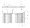
図3を参照すると、本発明に係る二次電池の分解断面図が図示されており、図4を参照すると、本発明に係る二次電池において、キャッププレートの平面図が図示されている。 Referring to FIG. 3, an exploded cross-sectional view of the secondary battery according to the present invention is illustrated, and with reference to FIG. 4, a plan view of a cap plate is illustrated in the secondary battery according to the present invention.
図3及び図4を参照しながら本発明に係る二次電池の形成方法を説明すると、ベアセル状態の角形リチウムイオン電池は、略直六面体で形成される角形の絶縁性缶11と、この絶縁性缶11の内部に受容される電極組立体22と、絶縁性缶11の開放された上段と結合して缶の上段を封入する絶縁性キャッププレート200とを備えてなされる。
A method for forming a secondary battery according to the present invention will be described with reference to FIGS. 3 and 4. A rectangular lithium ion battery in a bare cell state includes a rectangular insulating can 11 formed of a substantially rectangular parallelepiped, and the insulating property. The
電極組立体22は薄板型、または、膜型で形成された正極13、セパレータ14及び負
極15の積層体を渦型で巻取して形成する。巻取時の正極及び負極間の短絡を防止するために負極の外側にはセパレータが更に追加される。
The
正極13は、導電性の優れる金属薄板、例えば、アルミニウムホイルからなる正極集電体と、その両面にコーティングされたリチウム系酸化物を主成分とする正極活物質層を含んでいる。正極13には正極活物質層が形成されていない正極集電体の領域に電極タブ(例えば、正極タブ)16が電気的に連結されている。
The
負極15は、伝導性の金属薄板、例えば、銅ホイルからなる負極集電体と、その両面にコーティングされた炭素材を主成分とする負極活物質層とを含んでいる。負極15にも負極活物質層が形成されていない負極集電体の領域に電極タブ(例えば、負極タブ)17が接続されている。
The
ここで、正極13及び負極15と、タブら16、17は極性を異にして配置されることもでき、タブら16、17が電極組立体22から引出される境界部にはタブ16、17と両電極13、15との間の短絡を防止するために絶縁テープが各々巻かれる。
Here, the
セパレータ14は、また、ポリエチレンやポリプロピレンやポリエチレンとポリプロピレンの共重合体(co−polymer)からなる。セパレータ14は、正極13及び負極13より幅を広くして形成することが電極間の短絡を防止することに有利である。
The
缶11は、略直六面体の形状を有する絶縁体、例えば、プラスチック、エンジニアリングプラスチック、または、その等価物で形成可能であるが、ここに、その材質を限るのではない。このような絶縁性缶11の開放された上段を通じて電極組立体22が受容されて絶縁性缶11は電極組立体及び電解液の容器の役割をすることになる。このように、本発明は、缶11自体が絶縁性であるから、従来のような端子の役割を遂行することはできない。また、本発明は、開口部が形成された缶11の上段の段差19が形成されており、下記のキャッププレート200は前記段差19に堅く結合可能になっている。
The
キャッププレート200は、絶縁性缶11の開放された上段に対応する大きさと形状を有する絶縁性平板形態で設けられている。このようなキャッププレート200は非金属絶縁材質、たとえ、プラスチック、エンジニアリングプラスチック、または、その等価物で形成可能であるが、ここに、その材質を限るのではない。
The
キャッププレート200には電極組立体22の電極タブ(例えば、正極タブ及び負極タブ)16、17が通過できるように連結ホール210が形成され、また、電解液注入のための電解液注入口230も形成される。合せて、このようなキャッププレート200は、前記缶11の上段に形成された段差19に結合した後、接着剤、または、熱融着方法により缶11に堅く固定される。
The
また、前記キャッププレート200を貫通するタブ16、17とキャッププレート200との間の隙間からは電解液が漏液してしまうので、このような隙間はタブをなす金属と結合性の良いプラスチック材質の熔接棒で熔接して埋め込むこともできる。しかし、キャッププレートと缶の開口部とを接着させた接着剤、または、接着性を有する充填材でその隙間を埋め込むことが加工性の面で好ましい。
In addition, since the electrolyte solution leaks from the gaps between the
従来、キャッププレート200の下面にあった絶縁プレート、端子プレート、電極端子、ガスケット等は本発明では必要でないので除去される。また、電極タブが多数回折り曲げられて内部に熔接されなくて、真直ぐに伸びて引出できるので、電極組立体上に置かれていたPP(polypropylene)ケース、または、絶縁ケースも省略されることができる。
Conventionally, the insulating plate, the terminal plate, the electrode terminal, the gasket, and the like on the lower surface of the
従って、本発明は、前記除去された構成要素だけ電極組立体22の高さを一層高めることができ、これによって、電池容量の向上が可能になる。勿論、前記のような構成要素の除去によって組立工程が単純になることは勿論、製造コストも低減する。更に、金属性の缶及びキャッププレートの代わりにプラスチック系列の缶及びキャッププレートを用いることにより、その重さは一層軽くなる。
Therefore, according to the present invention, the height of the
一方、電解液を注入する電解液注入口230はアルミニウムボールを圧入し、熔接して仕上げるよりは、プラスチック栓220で仕上げることができるように段差を置いて形成されている。栓を塞ぐ時は封入力を高めるために接着剤が使われ、栓と電解液注入口にねじ山を形成してねじ結合させることも可能である。接着剤の代わりにプラスチック熔接が用いられることもある。絶縁ケースがないので、電解液注入もより速かになされることができる。
On the other hand, the electrolytic
図5を参照すると、本発明に係る二次電池において保護回路基板を接続する状態が示されている。 Referring to FIG. 5, a state in which the protection circuit board is connected in the secondary battery according to the present invention is shown.
図5に図示された二次電池の形成方法は、図3ないし図4に図示された実施の形態における説明と類似している。ただ、キャッププレート200と缶11の開口部とを結合させることは接着剤240で行っており、電極タブ16、17が引出されるように形成されたキャッププレート200のホールと電極タブとの間の隙間を封入することも接着剤250で行っている。
The method for forming the secondary battery shown in FIG. 5 is similar to the description in the embodiment shown in FIGS. However, the bonding of the
キャッププレートのホールを通じて引出される電極タブ16、17は、それ自体で保護回路基板300のリードプレート320と熔接などの方法により結合する。図面符号310は外部入出力端子を示す。
The
このような構成において、後続的に、保護回路基板とベアセルとが結合したコアセル状態で二次電池はモールドに装着される。モールド内にホットメルト樹脂が注入され、冷却、または、硬化により保護回路基板とベアセルとが隙間なしに結合して外観が完成されたハードパック状態の電池をなすことになる。 In such a configuration, subsequently, the secondary battery is mounted on the mold in a core cell state in which the protection circuit board and the bare cell are coupled. A hot-melt resin is injected into the mold, and the protective circuit board and the bare cell are joined without gaps by cooling or curing to form a hard-packed battery whose appearance is completed.
以上の実施の形態で使われることができるプラスチックとしては、金属との熔接性、加工性の優れるエンジニアリングプラスチック類を使用することが好ましい。最近開発されたエンジニアリングプラスチックは、アルミニウムより軽く、高い機械的強度を維持できるもの等があり、接着剤は電解質により分解したり変性されたりしないように、耐化学性、耐熱性を有するものを使用することが好ましい。 As the plastic that can be used in the above embodiments, it is preferable to use engineering plastics that are excellent in weldability to metal and workability. Recently developed engineering plastics are lighter than aluminum and can maintain high mechanical strength. Use adhesives that have chemical resistance and heat resistance so that they are not decomposed or modified by electrolytes. It is preferable to do.
たとえば、絶縁性缶とキャッププレートとが接する所を密着させる接着剤としてはエポキシなどを使うことができる。その際、エポキシは加工効率を上げるために硬化時間を短くすることが好ましい。 For example, an epoxy or the like can be used as an adhesive that closely contacts the place where the insulating can and the cap plate are in contact with each other. At that time, it is preferable to shorten the curing time of the epoxy in order to increase the processing efficiency.
また、以上の例では、絶縁性缶11を使用する場合を例示したが、金属性缶を使用することもできる。
Moreover, although the case where the insulating
そして、以上の例ではキャッププレートに電極タブの引出のための中央ホールを形成する形態を表したが、キャッププレートの周り部にタブの引出のための溝を形成し、キャッププレートと缶の開口部とが会う所に、この溝により電極タブの引出しのためのホールが形成される効果を有する他の本発明の実施の形態を提示することも可能である。 In the above example, the center hole for drawing out the electrode tab is formed in the cap plate. However, a groove for drawing out the tab is formed around the cap plate to open the cap plate and the can. It is also possible to present another embodiment of the present invention having the effect of forming a hole for drawing out the electrode tab by this groove at the place where the section meets.
本発明は、二次電池の小型化におおいに寄与することができる。 The present invention can greatly contribute to downsizing of the secondary battery.
11 缶、
22 電極組立体、
200 キャッププレート、
210 連結ホール、
220 栓、
230 電解液注入口、
240、250 接着剤。
11 cans,
22 electrode assembly,
200 cap plate,
210 connecting hole,
220 stoppers,
230 Electrolyte inlet,
240, 250 Adhesive.
Claims (24)
前記電極組立体を受容できるように上部に開口部が形成されたケースと、
前記電極組立体が外部に離脱しないように前記開口部を閉塞する絶縁材質のキャッププレートを備えたキャップ組立体と、
を含んでなることを特徴とする二次電池。 An electrode assembly comprising both electrodes and a separator;
A case in which an opening is formed in the upper part so as to receive the electrode assembly;
A cap assembly comprising a cap plate made of an insulating material that closes the opening so that the electrode assembly does not leave the outside;
A secondary battery comprising:
前記電極組立体を受容できるように上部に開口部が形成された絶縁材質のケースと、
前記電極組立体が外部に離脱しないように前記開口部を閉塞する絶縁材質のキャッププレートを基本的に備えたキャップ組立体と、
を含んでなることを特徴とする二次電池。 An electrode assembly comprising both electrodes and a separator;
A case made of an insulating material having an opening formed at the top so as to receive the electrode assembly;
A cap assembly basically comprising a cap plate made of an insulating material that closes the opening so that the electrode assembly does not leave the outside;
A secondary battery comprising:
Applications Claiming Priority (4)
| Application Number | Priority Date | Filing Date | Title |
|---|---|---|---|
| KR10-2004-0086895 | 2004-10-28 | ||
| KR1020040086905A KR100614358B1 (en) | 2004-10-28 | 2004-10-28 | Can type rechargeable battery |
| KR1020040086895A KR100614397B1 (en) | 2004-10-28 | 2004-10-28 | Secondary battery |
| KR10-2004-0086905 | 2004-10-28 |
Publications (2)
| Publication Number | Publication Date |
|---|---|
| JP2006128126A true JP2006128126A (en) | 2006-05-18 |
| JP4749832B2 JP4749832B2 (en) | 2011-08-17 |
Family
ID=36316708
Family Applications (1)
| Application Number | Title | Priority Date | Filing Date |
|---|---|---|---|
| JP2005314804A Expired - Fee Related JP4749832B2 (en) | 2004-10-28 | 2005-10-28 | Secondary battery |
Country Status (2)
| Country | Link |
|---|---|
| US (1) | US20060099501A1 (en) |
| JP (1) | JP4749832B2 (en) |
Cited By (3)
| Publication number | Priority date | Publication date | Assignee | Title |
|---|---|---|---|---|
| JP2011108623A (en) * | 2009-11-16 | 2011-06-02 | Samsung Sdi Co Ltd | Secondary battery |
| KR101052410B1 (en) * | 2011-01-10 | 2011-07-28 | 주식회사 태성포리테크 | Electrodes with cathode for battery and manufacturing method thereof |
| KR101052369B1 (en) | 2011-01-10 | 2011-07-28 | 주식회사 태성포리테크 | Electrodes with welded anode for battery and manufacturing method thereof |
Families Citing this family (13)
| Publication number | Priority date | Publication date | Assignee | Title |
|---|---|---|---|---|
| KR100709834B1 (en) * | 2005-04-26 | 2007-04-23 | 삼성에스디아이 주식회사 | Secondary battery |
| KR100984367B1 (en) * | 2008-07-03 | 2010-09-30 | 삼성에스디아이 주식회사 | Secondary battery comprising Electrolyte Injection-hole and Fabricating method the same |
| US9029007B2 (en) * | 2009-04-03 | 2015-05-12 | Samsung Sdi Co., Ltd. | Rechargeable battery including first and second metallic plates coupled together and a cap assembly including an insulator |
| KR101050306B1 (en) * | 2009-06-29 | 2011-07-19 | 삼성에스디아이 주식회사 | Secondary battery |
| KR20110066448A (en) * | 2009-12-11 | 2011-06-17 | 삼성에스디아이 주식회사 | Lithium secondary battery |
| KR101233491B1 (en) * | 2010-12-15 | 2013-02-14 | 삼성에스디아이 주식회사 | Secondary battery |
| KR101234241B1 (en) * | 2011-02-17 | 2013-02-18 | 삼성에스디아이 주식회사 | Rechargeable Battery pack |
| KR101683203B1 (en) | 2011-09-19 | 2016-12-21 | 삼성에스디아이 주식회사 | Rechargeable battery |
| DE102013002152A1 (en) * | 2013-02-07 | 2014-08-07 | Volkswagen Aktiengesellschaft | Electrical storage cell for use in electrical storage module of vehicle, has electrical non-conductive insulating jacket including electrical non-conductive cell cover that covers top surface of cell case along boundary to cell case |
| KR101596269B1 (en) | 2013-02-13 | 2016-02-23 | 주식회사 엘지화학 | Battery Cell of Novel Structure |
| KR102303827B1 (en) | 2014-10-06 | 2021-09-17 | 삼성전자주식회사 | Complex electrode assembly including a plurality of electrode assemblies and electrochemical device comprising the complex electrode assembly |
| EP3367458B1 (en) * | 2017-02-23 | 2022-11-30 | Robert Bosch GmbH | Secondary cell for a traction battery and method for manufacturing a secondary cell |
| WO2022126328A1 (en) * | 2020-12-14 | 2022-06-23 | 宁德新能源科技有限公司 | Battery and electronic device using same |
Citations (12)
| Publication number | Priority date | Publication date | Assignee | Title |
|---|---|---|---|---|
| JPS61240565A (en) * | 1985-04-18 | 1986-10-25 | Matsushita Electric Ind Co Ltd | Sealed lead-acid battery |
| JPS63155551A (en) * | 1986-12-19 | 1988-06-28 | Shin Kobe Electric Mach Co Ltd | Manufacture of enclosed type lead storage battery |
| JPH0762124A (en) * | 1993-08-23 | 1995-03-07 | Nagase Chiba Kk | Electric battery and electrical or electronic component sealed with resin |
| JPH08204307A (en) * | 1995-01-27 | 1996-08-09 | Taiyo Furoro Kk | Structure for surface mounting type insulating board of electric circuit element |
| JPH0977960A (en) * | 1995-09-14 | 1997-03-25 | Sumitomo Chem Co Ltd | Thin battery |
| JPH11214856A (en) * | 1998-01-20 | 1999-08-06 | Sumitomo Electric Ind Ltd | Hard case |
| JP2000149888A (en) * | 1998-11-13 | 2000-05-30 | Mitsubishi Cable Ind Ltd | Pack case for lithium battery |
| JP2001052661A (en) * | 1999-08-09 | 2001-02-23 | Sumitomo Electric Ind Ltd | Sealing sack for nonaqueous electrolyte battery |
| JP2001351691A (en) * | 2000-06-09 | 2001-12-21 | Gs-Melcotec Co Ltd | Nonaqueous electrolyte secondary cell |
| JP2004006159A (en) * | 2002-05-31 | 2004-01-08 | Sanyo Electric Co Ltd | Battery pack of nonaqueous electrolyte secondary battery |
| JP2004006157A (en) * | 2002-05-31 | 2004-01-08 | Sanyo Electric Co Ltd | Manufacturing method of battery pack, and battery pack |
| JP2004006158A (en) * | 2002-05-31 | 2004-01-08 | Sanyo Electric Co Ltd | Battery pack |
Family Cites Families (15)
| Publication number | Priority date | Publication date | Assignee | Title |
|---|---|---|---|---|
| US5413660A (en) * | 1993-10-26 | 1995-05-09 | Rohm And Haas Company | Method for imparting improved adhesion to polyolefin substrates |
| EP0975031B2 (en) * | 1998-02-05 | 2011-11-02 | Dai Nippon Printing Co., Ltd. | Sheet for cell case and cell device |
| JP3418551B2 (en) * | 1998-06-12 | 2003-06-23 | 日本碍子株式会社 | Lithium secondary battery |
| JP4193271B2 (en) * | 1999-03-12 | 2008-12-10 | ソニー株式会社 | Solid electrolyte battery |
| KR100322098B1 (en) * | 1999-11-18 | 2002-02-06 | 김순택 | Secondary battery |
| JP2001307712A (en) * | 2000-04-19 | 2001-11-02 | Nec Mobile Energy Kk | Encapsulated battery |
| JP4060562B2 (en) * | 2001-05-02 | 2008-03-12 | 日本碍子株式会社 | Electrode body evaluation method |
| AU2002315399A1 (en) * | 2001-06-21 | 2003-01-08 | Black And Decker Inc. | Method and apparatus for fastening steel framing by crimping |
| KR100472504B1 (en) * | 2002-06-17 | 2005-03-10 | 삼성에스디아이 주식회사 | Pouch type secondary battery with improved reinforcement structure |
| KR20040054128A (en) * | 2002-12-17 | 2004-06-25 | 삼성에스디아이 주식회사 | Pouched-type lithium secondary battery |
| US7491464B2 (en) * | 2003-01-03 | 2009-02-17 | The Gillette Company | Alkaline cell with flat housing |
| KR100484115B1 (en) * | 2003-05-21 | 2005-04-19 | 삼성에스디아이 주식회사 | Secondary battery |
| JP4238645B2 (en) * | 2003-06-12 | 2009-03-18 | 日産自動車株式会社 | Bipolar battery |
| KR100954031B1 (en) * | 2004-09-24 | 2010-04-20 | 삼성에스디아이 주식회사 | Secondary battery having jelly roll type electrode assembly |
| KR100579376B1 (en) * | 2004-10-28 | 2006-05-12 | 삼성에스디아이 주식회사 | Secondary battery |
-
2005
- 2005-10-27 US US11/261,392 patent/US20060099501A1/en not_active Abandoned
- 2005-10-28 JP JP2005314804A patent/JP4749832B2/en not_active Expired - Fee Related
Patent Citations (12)
| Publication number | Priority date | Publication date | Assignee | Title |
|---|---|---|---|---|
| JPS61240565A (en) * | 1985-04-18 | 1986-10-25 | Matsushita Electric Ind Co Ltd | Sealed lead-acid battery |
| JPS63155551A (en) * | 1986-12-19 | 1988-06-28 | Shin Kobe Electric Mach Co Ltd | Manufacture of enclosed type lead storage battery |
| JPH0762124A (en) * | 1993-08-23 | 1995-03-07 | Nagase Chiba Kk | Electric battery and electrical or electronic component sealed with resin |
| JPH08204307A (en) * | 1995-01-27 | 1996-08-09 | Taiyo Furoro Kk | Structure for surface mounting type insulating board of electric circuit element |
| JPH0977960A (en) * | 1995-09-14 | 1997-03-25 | Sumitomo Chem Co Ltd | Thin battery |
| JPH11214856A (en) * | 1998-01-20 | 1999-08-06 | Sumitomo Electric Ind Ltd | Hard case |
| JP2000149888A (en) * | 1998-11-13 | 2000-05-30 | Mitsubishi Cable Ind Ltd | Pack case for lithium battery |
| JP2001052661A (en) * | 1999-08-09 | 2001-02-23 | Sumitomo Electric Ind Ltd | Sealing sack for nonaqueous electrolyte battery |
| JP2001351691A (en) * | 2000-06-09 | 2001-12-21 | Gs-Melcotec Co Ltd | Nonaqueous electrolyte secondary cell |
| JP2004006159A (en) * | 2002-05-31 | 2004-01-08 | Sanyo Electric Co Ltd | Battery pack of nonaqueous electrolyte secondary battery |
| JP2004006157A (en) * | 2002-05-31 | 2004-01-08 | Sanyo Electric Co Ltd | Manufacturing method of battery pack, and battery pack |
| JP2004006158A (en) * | 2002-05-31 | 2004-01-08 | Sanyo Electric Co Ltd | Battery pack |
Cited By (4)
| Publication number | Priority date | Publication date | Assignee | Title |
|---|---|---|---|---|
| JP2011108623A (en) * | 2009-11-16 | 2011-06-02 | Samsung Sdi Co Ltd | Secondary battery |
| US9099696B2 (en) | 2009-11-16 | 2015-08-04 | Samsung Sdi Co., Ltd. | Secondary battery |
| KR101052410B1 (en) * | 2011-01-10 | 2011-07-28 | 주식회사 태성포리테크 | Electrodes with cathode for battery and manufacturing method thereof |
| KR101052369B1 (en) | 2011-01-10 | 2011-07-28 | 주식회사 태성포리테크 | Electrodes with welded anode for battery and manufacturing method thereof |
Also Published As
| Publication number | Publication date |
|---|---|
| JP4749832B2 (en) | 2011-08-17 |
| US20060099501A1 (en) | 2006-05-11 |
Similar Documents
| Publication | Publication Date | Title |
|---|---|---|
| JP4749832B2 (en) | Secondary battery | |
| KR100601577B1 (en) | Rechargeable battery | |
| JP5186529B2 (en) | Lithium secondary battery | |
| US8137836B2 (en) | Lithium rechargeable battery with resin molding part and outer covers | |
| KR100839785B1 (en) | Rechargeable battery and Method of making the same | |
| JP4180574B2 (en) | Square secondary battery with lead plate attached | |
| US20070202364A1 (en) | Secondary battery | |
| US8603669B2 (en) | Protection circuit assembly and battery pack having the same | |
| KR100537539B1 (en) | Prismatic type secondary battery having lead plate | |
| KR100973314B1 (en) | Protection circuit assembly and battery pack using the same | |
| JP2005129528A (en) | Secondary battery | |
| JP2011077023A (en) | Current breaking element, and secondary battery equipped with the same | |
| JP4769780B2 (en) | Secondary battery | |
| KR20080038663A (en) | Secondary battery | |
| KR100614358B1 (en) | Can type rechargeable battery | |
| KR100795681B1 (en) | Secondary battery | |
| KR100994954B1 (en) | Secondary battery which protective circuit board is connected | |
| KR100614397B1 (en) | Secondary battery | |
| KR20080034723A (en) | Rechargeable battery | |
| KR101264462B1 (en) | Rechargeable battery riveting lead plate and bare cell | |
| KR100760786B1 (en) | Secondary battery and the same using method | |
| KR100686831B1 (en) | Secondary battery and the same using method | |
| KR100571232B1 (en) | Lead plate and can type secondary battery using the same | |
| KR20080036738A (en) | Secondary battery and method therefor | |
| KR100624909B1 (en) | Can type rechargeable battery |
Legal Events
| Date | Code | Title | Description |
|---|---|---|---|
| A131 | Notification of reasons for refusal |
Free format text: JAPANESE INTERMEDIATE CODE: A131 Effective date: 20090512 |
|
| A521 | Request for written amendment filed |
Free format text: JAPANESE INTERMEDIATE CODE: A523 Effective date: 20090806 |
|
| A131 | Notification of reasons for refusal |
Free format text: JAPANESE INTERMEDIATE CODE: A131 Effective date: 20100209 |
|
| A521 | Request for written amendment filed |
Free format text: JAPANESE INTERMEDIATE CODE: A523 Effective date: 20100510 |
|
| A01 | Written decision to grant a patent or to grant a registration (utility model) |
Free format text: JAPANESE INTERMEDIATE CODE: A01 Effective date: 20110510 |
|
| A01 | Written decision to grant a patent or to grant a registration (utility model) |
Free format text: JAPANESE INTERMEDIATE CODE: A01 |
|
| A61 | First payment of annual fees (during grant procedure) |
Free format text: JAPANESE INTERMEDIATE CODE: A61 Effective date: 20110518 |
|
| R150 | Certificate of patent or registration of utility model |
Free format text: JAPANESE INTERMEDIATE CODE: R150 |
|
| FPAY | Renewal fee payment (event date is renewal date of database) |
Free format text: PAYMENT UNTIL: 20140527 Year of fee payment: 3 |
|
| R250 | Receipt of annual fees |
Free format text: JAPANESE INTERMEDIATE CODE: R250 |
|
| R250 | Receipt of annual fees |
Free format text: JAPANESE INTERMEDIATE CODE: R250 |
|
| LAPS | Cancellation because of no payment of annual fees |