JP2006123740A - Structure of luggage compartment board - Google Patents
Structure of luggage compartment board Download PDFInfo
- Publication number
- JP2006123740A JP2006123740A JP2004315128A JP2004315128A JP2006123740A JP 2006123740 A JP2006123740 A JP 2006123740A JP 2004315128 A JP2004315128 A JP 2004315128A JP 2004315128 A JP2004315128 A JP 2004315128A JP 2006123740 A JP2006123740 A JP 2006123740A
- Authority
- JP
- Japan
- Prior art keywords
- compartment board
- cargo compartment
- seat back
- backrest
- board
- Prior art date
- Legal status (The legal status is an assumption and is not a legal conclusion. Google has not performed a legal analysis and makes no representation as to the accuracy of the status listed.)
- Withdrawn
Links
Images
Classifications
-
- B—PERFORMING OPERATIONS; TRANSPORTING
- B60—VEHICLES IN GENERAL
- B60N—SEATS SPECIALLY ADAPTED FOR VEHICLES; VEHICLE PASSENGER ACCOMMODATION NOT OTHERWISE PROVIDED FOR
- B60N2/00—Seats specially adapted for vehicles; Arrangement or mounting of seats in vehicles
- B60N2/24—Seats specially adapted for vehicles; Arrangement or mounting of seats in vehicles for particular purposes or particular vehicles
- B60N2/32—Seats specially adapted for vehicles; Arrangement or mounting of seats in vehicles for particular purposes or particular vehicles convertible for other use
- B60N2/36—Seats specially adapted for vehicles; Arrangement or mounting of seats in vehicles for particular purposes or particular vehicles convertible for other use into a loading platform
- B60N2002/363—Seats specially adapted for vehicles; Arrangement or mounting of seats in vehicles for particular purposes or particular vehicles convertible for other use into a loading platform characterised by provisions for enhancing the cargo floor surface, e.g. elements closing gaps or enlarging the back-rest surface
Landscapes
- Seats For Vehicles (AREA)
- Passenger Equipment (AREA)
Abstract
Description
本発明は、起伏自在な背もたれ部を備えるシートと荷室ボードが近接配置された荷室ボード構造に関する。 The present invention relates to a cargo compartment board structure in which a seat having a backrest that can be raised and lowered and a cargo compartment board are arranged close to each other.
従来、ワゴンタイプのように居室と荷室がつながっている車両にあっては、起伏自在な背もたれ部が居室と荷室とを区画している。このような起伏自在な背もたれ部と荷室ボードが近接配置されたものでは、シートの背もたれ部を座部の上に倒伏させて水平状にし、荷室の床を構成する荷室ボードとの間でフルフラットルになるように構成される。ところが、倒伏させて水平状にされた背もたれ部と荷室ボードとの間の隙間から物品が落下しがちであった。このため、狭い空間に手を差し込んで落下物の回収をしなければならず、手間を要して面倒であった。そこで、背もたれ部と荷室ボードとの間の隙間を解消する技術が提案された(例えば下記特許文献1および2参照)。
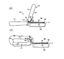
図4を用いて前記特許文献1に開示された車両用カーペット取付装置について説明する。シートバック112がシートクッション111に対して起伏自在なリヤシート110は、シートバック112の背面113がループ状生地で形成され、シートバック112の下面ニット生地115に車幅方向へ延びるループ状生地116が縫製されている。荷室120のカーペット123の前方側端部の裏面にそれぞれ車幅方向へ延びて鉤状生地である第1シート126および第2シート127が縫製されていて、シートバック背面113と第1シート126とが、また、ループ状生地116と第2シート127とが、それぞれ着脱可能な面ファスナーを構成している。これにより、車両のシート後方おける荷室のカーペットを容易に着脱して、荷室の見栄えをよくするとともに、シートバック112と荷室のカーゴボード121との間に物が落下するのを防止できる。
The vehicle carpet mounting apparatus disclosed in Patent Document 1 will be described with reference to FIG. In the
図5を用いて前記特許文献2に開示された車両荷室構造について説明する。シートバック207の背面207a側および荷室フロア203の上面203a側に止着される背面マット部材212を備え、シートバック207における背面マット部材212の荷室フロア203側の止着部Aが、シートバック207の前倒時に、シートバック207の回動中心Oの略上方となるようにし、シートバック207が起立すると、背面マット部材212が間隙204内にて弛緩するように構成したものである。これにより、部品点数が低減され、製造コストの低減も図れて、車両用シートのシートバック207が前倒状態であっても、車両室内の美観を損なうことがない。
The vehicle luggage compartment structure disclosed in
しかしながら、このような従来のものにあって、いずれのものもシートバック(背もたれ部)に止着されるマット部材あるいはシートの止着部が、せいぜいシートバックの倒伏位置における回動中心の上方に留まっている。このため、シートバックの起立使用時と倒伏格納時との間で、マット部材あるいはシートのたるみ長さを充分に採ることができず、シートバックの回動中心位置に規制を受けたり、シートバックと荷室フロア部203との間隔をぎりぎりまで近接させる必要があって、設計の自由度が減少した。
However, in such conventional devices, the mat member or the seat fixing portion that is fixed to the seat back (backrest portion) is at most above the center of rotation in the lying position of the seat back. Stays. For this reason, the slack length of the mat member or the seat cannot be taken sufficiently between the standing use of the seat back and the storage of the seat back, and the seat back is restricted by the rotation center position. And the
そこで本発明は、このような従来の荷室ボード構造の課題を解決して、荷室ボードとシートの背もたれ部との間に貼着したマット部材に充分なたるみ部を形成して、背もたれ部の自在な起伏と、荷室ボードの起伏をも可能にした荷室ボード構造を提供することを目的とする。 Therefore, the present invention solves such a problem of the conventional cargo compartment board structure, forms a sufficient slack portion on the mat member adhered between the cargo compartment board and the seat backrest portion, and forms a backrest portion. It is an object of the present invention to provide a cargo compartment board structure that can freely raise and lower the cargo compartment board and the cargo board.
このため本発明は、起伏自在な背もたれ部を備えるシートと荷室ボードが近接配置された荷室ボード構造において、背もたれ部背面から荷室ボード上面にわたり添設されたマット部材の背もたれ部への貼着部終点が、背もたれ部の格納倒伏時において背もたれ部の軸支点より充分に前方に位置させたことを特徴とする。また本発明は、前記荷室ボードの前端部両側近傍に、荷室ボードの起立時に荷室ボードの前端部近傍を受け入れる受部材を設置したことを特徴とする。また本発明は、前記受部材がトリム部材に形成された溝部であることを特徴とする。また本発明は、前記荷室ボードの後端部近傍に荷室ボードの位置決め部材を設置したことを特徴とするもので、これらを課題解決のための手段とするものである。 For this reason, the present invention relates to a luggage compartment board structure in which a seat having a undulating backrest portion and a cargo compartment board are arranged close to each other, and is attached to the backrest portion of a mat member attached from the back of the backrest portion to the upper surface of the cargo compartment board. The landing end point is located sufficiently forward of the pivot point of the backrest when the backrest is retracted. Further, the present invention is characterized in that receiving members for receiving the vicinity of the front end portion of the cargo compartment board when the cargo compartment board stands up are provided in the vicinity of both sides of the front end portion of the cargo compartment board. Further, the invention is characterized in that the receiving member is a groove formed in the trim member. Further, the present invention is characterized in that a positioning member for the cargo compartment board is installed in the vicinity of the rear end of the cargo compartment board, and these are used as means for solving the problems.
本発明によれば、起伏自在な背もたれ部を備えるシートと荷室ボードが近接配置された荷室ボード構造において、背もたれ部背面から荷室ボード上面にわたり添設されたマット部材の背もたれ部への貼着部終点が、背もたれ部の格納倒伏時において背もたれ部の軸支点より充分に前方に位置させたことにより、外観に優れることは無論、物品の落下の虞れもなく、背もたれ部を倒伏格納した状態から起立使用状態まで、背もたれ部背面から荷室ボード上面にわたり添設されたマット部材に充分なたるみ部を形成させることが可能で、背もたれ部軸支点の位置の規制や荷室ボードとの配置関係に厳密な規制を受けることがなく、自在な背もたれ部の起伏が可能で、荷室ボードの起立等もマット部材にあまり影響されずに行える。 According to the present invention, in a cargo compartment board structure in which a seat having a undulating backrest portion and a cargo compartment board are arranged close to each other, the mat member attached from the back of the backrest portion to the upper surface of the cargo compartment board is attached to the backrest portion. When the landing part end point is located sufficiently forward from the pivot point of the backrest part when retracting the backrest part, it is of course superior in appearance and there is no risk of the article falling, and the backrest part is stored in a lying position. From the state to the standing use state, it is possible to form a sufficient slack part on the mat member attached from the back of the back part to the upper surface of the luggage room board, regulation of the position of the back part shaft fulcrum and arrangement with the luggage room board There is no strict regulation on the relationship, the backrest portion can be freely raised and lowered, and the cargo room board can be raised without much influence from the mat member.
また、前記荷室ボードの前端部両側近傍に、荷室ボードの起立時に荷室ボードの前端部近傍を受け入れる受部材を設置した場合は、前記充分なマット部材のたるみ部の確保によって、マット部材を上面に貼着させた荷室ボードの前端部近傍を受部材に支持させて荷室ボードを起立保持させても、何らマット部材を突っ張らせることなく、荷室ボード下部内に格納されたスペアタイヤ等を容易に取り出すことができる。 In addition, when a receiving member that receives the vicinity of the front end portion of the cargo compartment board when the cargo compartment board is raised is installed near both sides of the front end portion of the cargo compartment board, the mat member can be secured by securing a slack portion of the mat member. Spare housed in the lower part of the cargo compartment board without any mat member being stretched even if the cargo compartment board is held upright with the receiving member supporting the vicinity of the front end of the cargo compartment board attached to the upper surface. Tires and the like can be easily taken out.
さらに、前記受部材がトリム部材に形成された溝部である場合は、車体パネル等に何らの設計を施すことなく、トリム部材に荷室ボードの前端部近傍を受け入れる溝部を形成すればよいので、溝部を形成したトリム部材の交換等により、容易に荷室ボードを起立保持可能なタイプに変更することができる。さらにまた、前記荷室ボードの後端部近傍に荷室ボードの位置決め部材を設置した場合は、荷室ボードの定位置を正確に位置決めすることができ、タイヤ交換後の荷室ボードの位置リセットが正確に行え、再度、荷室ボードを起立させる際に、その前端部近傍を正確に溝部等の受入れ部に落とし込むことができる。 Furthermore, when the receiving member is a groove formed in the trim member, the groove member for receiving the vicinity of the front end portion of the cargo compartment board may be formed in the trim member without any design on the vehicle body panel or the like. The luggage compartment board can be easily changed to a type that can be held upright by replacing the trim member in which the groove is formed. Furthermore, when a cargo compartment board positioning member is installed in the vicinity of the rear end portion of the cargo compartment board, it is possible to accurately position the cargo compartment board, and the position of the cargo compartment board after tire replacement is reset. When the cargo compartment board is raised again, the vicinity of the front end can be accurately dropped into a receiving portion such as a groove.
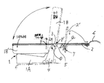
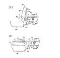
以下、本発明の実施例を図面に基づいて説明する。図1は本発明の荷室ボード構造の1つの実施例を示す全体側面図、図2は車両後部の概略斜視図、図3は荷室ボードの後部位置決め部を含む側面図である。本発明の荷室ボード構造の基本的な構造は、図1に示すように、起伏自在な背もたれ部1Bを備えるシート1と荷室ボード2が近接配置された荷室ボード構造において、背もたれ部1B背面から荷室ボード2上面にわたり添設されたマット部材3の背もたれ部への貼着部終点Pが、背もたれ部1Bの格納倒伏時において背もたれ部1Bの軸支点Oより充分に前方に位置させたことを特徴とするものである。
Embodiments of the present invention will be described below with reference to the drawings. FIG. 1 is an overall side view showing an embodiment of a cargo compartment board structure according to the present invention, FIG. 2 is a schematic perspective view of a rear portion of a vehicle, and FIG. 3 is a side view including a rear positioning portion of the cargo compartment board. As shown in FIG. 1, the basic structure of the cargo compartment board structure of the present invention is a backrest portion 1B in a cargo compartment board structure in which a seat 1 having a backrest portion 1B that can be raised and lowered and a
実施例について以下に詳述する。図1に示すように、車体フロアパネル(二点鎖線)に固定された左右の支持ブラケット4、4の上部に軸支点Oが設けられ、該軸支点Oにシート1の背もたれ部1Bが起伏自在に支持される。また、前記支持ブラケット4、4間にはシート1の座部1の後部も設置される。シート1の後方には近接して荷室ボード2が配設される。前記背もたれ部1Bの倒伏格納時(符号1B’で示す)の背面と、荷室ボード2の倒伏時の上面とは略水平状にフルフラット状をなす。これらの背もたれ部1Bの背面と荷室ボード2の上面とにわたってマット部材3が添設されて貼着される。荷室ボード2の後端部はリヤエンドパネル6上に載置される。
Examples will be described in detail below. As shown in FIG. 1, a shaft fulcrum O is provided on the upper portions of the left and
前記背もたれ部1Bに添設されるマット部材3は、背もたれ部1Bの上端部から下端部にかけて貼着され、その貼着部終点Pは、背もたれ部1Bの格納倒伏時において背もたれ部1Bの軸支点Oより充分に前方(所定距離L)に位置させて構成される。したがって、貼着部終点Pより後方のマット部材3はたるみ部5としてる背もたれ部1Bの背面から開放される。これにより、背もたれ部1Bを二点鎖線のように充分に後傾させて使用状態に起立させても、たるみ部5が充分に確保されて、背もたれ部1Bの背面からマット部材3が剥離する虞れがない。
The mat member 3 attached to the backrest portion 1B is stuck from the upper end portion to the lower end portion of the backrest portion 1B, and the sticking portion end point P is a pivot point of the backrest portion 1B when the backrest portion 1B is retracted. It is configured to be positioned sufficiently ahead of O (predetermined distance L). Therefore, the mat member 3 behind the sticking portion end point P is released from the back surface of the backrest portion 1 </ b> B as the
荷室ボード2に添設されたマット部材3についても、マット部材貼着部終点Qは荷室ボード2の前端部から所定距離を隔てた位置にある。これにより、荷室ボード2の前端部近傍を受部材7に支持させて荷室ボード2を起立保持(二点鎖線2’位置)させても、何らマット部材3を突っ張らせることなく、荷室ボード2下部内に格納されたスペアタイヤ等を容易に取り出すことを可能とする。
As for the mat member 3 attached to the
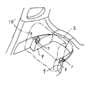
図2に示すように、荷室ボード2(太実線)の前端部両側には略方形の切欠8、8が設けられ、該切欠8の後縁が、荷室ボード2の起立時に受部材である溝部7、7に落とし込まれて、荷室ボード2の起立時の揺動中心となる。前記溝部7、7は車体パネル内に装着された内装材であるトリム部材9、9に形成される。この場合は、車体パネル等に溝部等の何らの加工を施すことなく、トリム部材9に溝部7を形成するか、溝部7を形成したトリム部材9の交換等により、容易に荷室ボード2を起立保持可能なタイプに変更することができる。無論、前記溝部を車体パネル等に形成することを妨げるものではない。
As shown in FIG. 2, substantially rectangular cutouts 8 are provided on both sides of the front end portion of the cargo compartment board 2 (thick solid line), and the rear edge of the cutout 8 is a receiving member when the
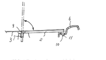
図3は荷室ボードの後部位置決め部を含む側面図である。荷室ボード2の後端部近傍に荷室ボード2の位置決め部材(突起)10を設置したものである。該位置決め突起10は略L字形を呈しており、リヤエンドパネル6の受面に穿設された位置決め孔11に挿入・係止される。これにより、荷室ボード2の定位置を正確に位置決めすることができ、タイヤ交換等の後の荷室ボード2の位置リセットが正確に行え、再度、荷室ボード2を一点鎖線のように起立させる際に、その前端部近傍を正確に溝部7等の受入れ部に落とし込むことができる。
FIG. 3 is a side view including a rear positioning portion of the cargo compartment board. A positioning member (protrusion) 10 of the
以上、本発明の各実施の形態について説明してきたが、本発明の趣旨の範囲内で、背もたれ部の形状、形式(1つの背もたれ部を有する単形式でも左右分割式でもよい。分割式の場合は、マット部材も貼着部終点近傍で分割構成とされる)およびその車体への軸支・揺動形態(支持ブラケットの形状や軸支のための軸受構造等は適宜選定される)、荷室ボードの形状(前方後円形状等の他、方形等の平面視形状、側面視形状についても必ずしも平板状でなくてもよい)、形式およびその車体への設置形態(単なる載置形式の他、容易に脱着できる簡素なフック機構を用いて軽く車体やトリム部材に装着することもできる)ならびに受部材への係止形態(切欠の形状、切欠を形成することなく貼着部終点より前方の荷室ボード前端部を受部材に落とし込むように構成することもできる)等については適宜選定することができる。 The embodiments of the present invention have been described above. However, the shape and form of the backrest part (a single form having one backrest part or a left / right split type may be used within the scope of the present invention. The mat member is also divided in the vicinity of the end point of the sticking part) and the shaft support / oscillation form to the vehicle body (the shape of the support bracket and the bearing structure for the shaft support are appropriately selected), the load The shape of the room board (in addition to the front and rear circular shape, etc., the planar view shape such as a square shape and the side view shape may not necessarily be flat), the form and the installation form on the vehicle body (in addition to the simple placement form) It can be lightly attached to the vehicle body or trim member using a simple hook mechanism that can be easily detached, and the locking form to the receiving member (the shape of the notch, the front of the sticking portion without forming the notch) The front end of the cargo compartment board is used as a receiving member And For even possible) or the like that is to configure so as to go can be appropriately selected.
また、マット部材の形状(好適には、背もたれ部背面および荷室ボード上面の形状に適合させるが、必ずしも全面を覆う必要はない)、形式(単一層、複数層)およびその材質(好適には起毛布材が採用されるが、適宜の素材が採用され得る)ならびにその背もたれ部および荷室ボードへの添設・貼着形態(背もたれ部背面および荷室ボード上面における貼着部終点の背もたれ部軸支点からの偏位量。貼着は、接着剤による他、適宜の係止具による係止等も採用され得る)、受部材の形状(幅、深さ、断面形状等)、形式(溝部が好適である)およびその設置部位(トリム部材、車体パネル等)、荷室ボードの位置決め部材の形状、形式(板状体、ピン等)およびそのリヤエンドパネル等への係止形態(突起と孔との組合せについては、いずれが突起でもよい)等についても適宜選定できる。 Also, the shape of the mat member (preferably adapted to the shape of the back of the backrest part and the upper surface of the cargo compartment board, but not necessarily covering the entire surface), the type (single layer, multiple layers) and its material (preferably Brushed cloth material is used, but any suitable material can be used) and its backrest and cargo room board attachment / attachment form (backrest back surface and back end of the adhesive section on the cargo room board upper surface) The amount of deviation from the shaft fulcrum.Attaching can be performed by using an adhesive or by using an appropriate locking device), the shape of the receiving member (width, depth, cross-sectional shape, etc.), type (groove) ) And its installation site (trim member, body panel, etc.), shape of the positioning member of the cargo compartment board, type (plate-like body, pin, etc.) and its locking form (projections and holes) to the rear end panel, etc. About the combination with There may also suitably selected for may also be), and the like in the protrusions.
1 シート
1A 座部
1B 背もたれ部
2 荷室ボード
3 マット部材
4 支持ブラケット
5 マット部材たるみ部
6 リヤエンドパネル
7 受部材(溝部)
8 前端部切欠
9 トリム部材
10 位置決め突起(位置決め部材)
11 位置決め孔(位置決め部材)
L 貼着部終点−軸支点間距離
O 背もたれ部軸支点
P マット部材貼着部終点(背もたれ部)
Q マット部材貼着部終点(荷室ボード)
1 seat 1A seat
8 Front end notch 9
11 Positioning hole (positioning member)
L Adhering part end point-shaft fulcrum distance O Backrest part axial fulcrum P Mat member adhering part end point (backrest part)
Q Matte material sticking part end point (cargo board)
Claims (4)
The cargo compartment board structure according to any one of claims 1 to 3, wherein a positioning member for the cargo compartment board is installed in the vicinity of a rear end portion of the cargo compartment board.
Priority Applications (1)
| Application Number | Priority Date | Filing Date | Title |
|---|---|---|---|
| JP2004315128A JP2006123740A (en) | 2004-10-29 | 2004-10-29 | Structure of luggage compartment board |
Applications Claiming Priority (1)
| Application Number | Priority Date | Filing Date | Title |
|---|---|---|---|
| JP2004315128A JP2006123740A (en) | 2004-10-29 | 2004-10-29 | Structure of luggage compartment board |
Publications (1)
| Publication Number | Publication Date |
|---|---|
| JP2006123740A true JP2006123740A (en) | 2006-05-18 |
Family
ID=36718879
Family Applications (1)
| Application Number | Title | Priority Date | Filing Date |
|---|---|---|---|
| JP2004315128A Withdrawn JP2006123740A (en) | 2004-10-29 | 2004-10-29 | Structure of luggage compartment board |
Country Status (1)
| Country | Link |
|---|---|
| JP (1) | JP2006123740A (en) |
Cited By (2)
| Publication number | Priority date | Publication date | Assignee | Title |
|---|---|---|---|---|
| JP2014080058A (en) * | 2012-10-15 | 2014-05-08 | Toyota Boshoku Corp | Vehicle seat |
| JP2018069844A (en) * | 2016-10-26 | 2018-05-10 | ダイハツ工業株式会社 | Vehicle deck board formation unit |
-
2004
- 2004-10-29 JP JP2004315128A patent/JP2006123740A/en not_active Withdrawn
Cited By (2)
| Publication number | Priority date | Publication date | Assignee | Title |
|---|---|---|---|---|
| JP2014080058A (en) * | 2012-10-15 | 2014-05-08 | Toyota Boshoku Corp | Vehicle seat |
| JP2018069844A (en) * | 2016-10-26 | 2018-05-10 | ダイハツ工業株式会社 | Vehicle deck board formation unit |
Similar Documents
| Publication | Publication Date | Title |
|---|---|---|
| US7195274B2 (en) | Vehicle seat component side air bag module having air bag guide including flexible inner and outer panels attached by module connector and frame connector and trim cover attached by frame connector | |
| JP5116368B2 (en) | Car seat for child seat mounting | |
| US7275786B2 (en) | Vehicle seat | |
| US20120319448A1 (en) | Vehicle seat and clip | |
| US20150321614A1 (en) | Internal map pocket | |
| US7862097B2 (en) | Storage and tread unit | |
| CA2879652A1 (en) | Bus seating system | |
| JP5407537B2 (en) | Vehicle seat | |
| JP2006123740A (en) | Structure of luggage compartment board | |
| JP5222774B2 (en) | Buckle device and seat belt device | |
| JP2018150000A (en) | Partition tool for seat | |
| JP3129045B2 (en) | Car seat | |
| JP6769379B2 (en) | Vehicle seat | |
| JP6347244B2 (en) | Vehicle seat structure | |
| JP2006347201A (en) | Luggage sheet | |
| JP6950441B2 (en) | Vehicle seat | |
| KR100478052B1 (en) | Luggage fixing net for automobile | |
| JP3760600B2 (en) | Automotive seat structure | |
| US20210101507A1 (en) | Child seat temporary holding structure in passenger motor vehicle | |
| EP2752135B1 (en) | Temporary sleeping arrangement | |
| JP4626421B2 (en) | Rear cargo compartment structure for vehicles | |
| WO2008023228A1 (en) | Vehicle seat and method of installing vehicle seat | |
| JP6699404B2 (en) | Vehicle seat | |
| JP3965992B2 (en) | Buckle support structure for vehicle seat belt | |
| JP2015116932A (en) | Interior structure of vehicle cabin |
Legal Events
| Date | Code | Title | Description |
|---|---|---|---|
| A300 | Withdrawal of application because of no request for examination |
Free format text: JAPANESE INTERMEDIATE CODE: A300 Effective date: 20080108 |