JP2006116552A - Method for manufacturing structural body having closed cross section - Google Patents
Method for manufacturing structural body having closed cross section Download PDFInfo
- Publication number
- JP2006116552A JP2006116552A JP2004304011A JP2004304011A JP2006116552A JP 2006116552 A JP2006116552 A JP 2006116552A JP 2004304011 A JP2004304011 A JP 2004304011A JP 2004304011 A JP2004304011 A JP 2004304011A JP 2006116552 A JP2006116552 A JP 2006116552A
- Authority
- JP
- Japan
- Prior art keywords
- closed cross
- section structure
- section
- flat
- cross
- Prior art date
- Legal status (The legal status is an assumption and is not a legal conclusion. Google has not performed a legal analysis and makes no representation as to the accuracy of the status listed.)
- Granted
Links
- 238000004519 manufacturing process Methods 0.000 title claims abstract description 38
- 238000000034 method Methods 0.000 title claims description 21
- 239000002184 metal Substances 0.000 claims abstract description 20
- 238000003825 pressing Methods 0.000 claims abstract description 10
- 238000003466 welding Methods 0.000 claims description 16
- 239000011265 semifinished product Substances 0.000 abstract description 38
- 238000010586 diagram Methods 0.000 description 9
- 238000003754 machining Methods 0.000 description 8
- 239000000463 material Substances 0.000 description 5
- 230000003014 reinforcing effect Effects 0.000 description 2
- 238000005452 bending Methods 0.000 description 1
- 238000005304 joining Methods 0.000 description 1
- 238000000465 moulding Methods 0.000 description 1
- 230000000630 rising effect Effects 0.000 description 1
- 238000009966 trimming Methods 0.000 description 1
- 239000013585 weight reducing agent Substances 0.000 description 1
Images


Abstract
Description
本発明は,平板をプレス成形して,突き合わせた両端を溶接により接合してなる閉断面構造体の製造方法に関する。 The present invention relates to a method for manufacturing a closed cross-section structure formed by press-molding a flat plate and joining the butted ends by welding.
かゝる閉断面構造体の製造方法は,下記特許文献1に開示されるように,既に知られている。
従来,かゝる閉断面構造体の製造に当たっては,中子の周囲に金属平板を巻き付けて成形するように,中子の上下に配設される下型及び上型を閉じるようにしているので,大型の成形型を必要とし,規模が大きいプレス設備を要し,したがって製造コストの低減が困難であり,その上,閉断面構造体の形状によっては,閉断面構造体からの中子の引き抜きが不可となるので,閉断面構造体の成形し得る形状に多くの制約があった。 Conventionally, in manufacturing such a closed cross-section structure, the lower mold and the upper mold arranged above and below the core are closed so that a metal flat plate is wound around the core. , Requires a large mold, requires a large-scale press facility, and therefore it is difficult to reduce the manufacturing cost. In addition, depending on the shape of the closed section structure, the core is pulled out from the closed section structure. Therefore, there are many restrictions on the shape of the closed cross-section structure that can be molded.
本発明は,かゝる事情に鑑みてなされたもので,中子を使用しない小規模なプレス設備でも金属平板から閉断面構造体を簡単に製造することができ,しかも閉断面構造体の成形し得る形状に制約が少ない閉断面構造体の製造方法を提供することを目的とする。 The present invention has been made in view of such circumstances, and a closed cross-section structure can be easily manufactured from a flat metal plate even in a small-scale press facility that does not use a core. An object of the present invention is to provide a method for manufacturing a closed cross-section structure with less restrictions on the shape that can be achieved.
上記目的を達成するために,本発明は,金属平板をプレス成形することで,断面平坦な連結部の両端から一対の閉断面構造体半部を立ち上がらせてなる半成品を製作する工程と,前記両閉断面構造体半部の間に挿入した偏平パンチにより前記連結部を内側から押圧して外側に隆起した屈曲部に成形しながら前記両閉断面構造体半部を更に立ち上がらせる工程と,前記両閉断面構造体半部間から前記偏平パンチを引き上げた後,前記両閉断面構造体半部の外端を相互に突き合わせて溶接する工程とを順次実行することを第1の特徴とする。 In order to achieve the above object, the present invention comprises a step of producing a semi-finished product by raising a pair of closed cross-section structure halves from both ends of a flat cross-section by pressing a flat metal plate, A step of further raising the both closed cross-section structure halves while forming the bent portion protruding outward by pressing the connecting portion from the inside with a flat punch inserted between the two closed cross-section structure halves; The first feature is to sequentially perform the steps of pulling up the flat punch from between the two closed cross-section structure halves and then welding the outer ends of the closed cross-section structure halves together.
また本発明は,第1の特徴に加えて,前記偏平パンチによる前記隆起部の成形時,前記両閉断面構造体半部に反りを発生させ,この前記両閉断面構造体半部の間から前記偏平パンチを引き上げたとき,前記両閉断面構造体半部の外端を前記反りの復元力により互いに突き合わせることを第2の特徴とする。 In addition to the first feature of the present invention, when the raised portion is formed by the flat punch, the two closed cross-section structure halves are warped, and between the two closed cross-section structure halves. A second feature is that when the flat punch is pulled up, the outer ends of the two closed cross-section structure halves abut against each other by the restoring force of the warp.
本発明の第1の特徴によれば,最終プレス工程で,半成品の両閉断面構造体半部の間に挿入した偏平パンチにより平坦部を内側から押圧して隆起部を成形しながら両閉断面構造体半部を,これらが偏平パンチを挟むように立ち上がらせるので,比較的小規模のプレス設備をもって,金属平板から各種形状の閉断面構造体の全体形状を得ることができ,その後,両閉断面構造体半部の外端同士を突き合わせて溶接することにより,所望の閉断面構造体を得ることができる。したがって,金属平板から用途に応じた各種所望形状の閉断面構造体を簡単に製造することができ,製造コストの低減に寄与し得る。 According to the first feature of the present invention, in the final pressing step, the double closed cross section is formed while pressing the flat portion from the inside by the flat punch inserted between the half closed cross section structure half portions of the semifinished product. Since the half of the structure rises so that they sandwich the flat punch, the overall shape of the closed cross-section structure of various shapes can be obtained from the metal flat plate with a relatively small press facility, A desired closed cross-section structure can be obtained by abutting and welding the outer ends of the half of the cross-section structure. Therefore, a closed cross-section structure having various desired shapes according to the application can be easily manufactured from a metal flat plate, which can contribute to reduction in manufacturing cost.
また本発明の第2の特徴によれば,偏平パンチによる隆起部の成形時後,両閉断面構造体半部間から偏平パンチを引き上げたとき,両閉断面構造体半部の外端を反りの復元力により互いに自然に突き合わせることができるので,次工程で,その外端突き合わせ部の溶接を容易に且つ確実に行うことができる。 Further, according to the second feature of the present invention, when the flat punch is pulled up between the two closed cross-section structure halves after forming the raised portion by the flat punch, the outer ends of the two closed cross-section structure halves are warped. Therefore, the outer end butting portion can be easily and reliably welded in the next step.
本発明の実施の形態を,図面に示す本発明の好適な実施例に基づき以下に説明する。 Embodiments of the present invention will be described below based on preferred embodiments of the present invention shown in the drawings.
図1は本発明の第1実施例の製造方法で製造される閉断面構造体の斜視図,図2は本発明の第1実施例を示す工程説明図,図3は本発明の第2実施例の製造方法で製造される閉断面構造体の斜視図,図4は本発明の第2実施例の製造方法を示す工程説明図,図5は本発明の第2実施例の製造方法で製造される別の閉断面構造体の斜視図,図6は同閉断面構造体の正面図,図7は図6の7−7線断面図,図8は図6の8−8線断面図,図9は本発明の第3実施例の製造方法で製造される閉断面構造体の斜視図,図10は本発明の第3実施例の製造方法を示す工程説明図,図11は本発明の第4実施例の製造方法で製造される閉断面構造体を示すもので,(A)は側面,(B)は底面図,(C)は(A)のC−C線断面図,図12は本発明の第4実施例の製造方法を示す工程説明図である。 FIG. 1 is a perspective view of a closed cross-section structure manufactured by the manufacturing method of the first embodiment of the present invention, FIG. 2 is a process explanatory view showing the first embodiment of the present invention, and FIG. 3 is a second embodiment of the present invention. FIG. 4 is a process explanatory view showing the manufacturing method of the second embodiment of the present invention, and FIG. 5 is manufactured by the manufacturing method of the second embodiment of the present invention. FIG. 6 is a front view of the closed cross-sectional structure, FIG. 7 is a cross-sectional view taken along line 7-7 in FIG. 6, and FIG. 8 is a cross-sectional view taken along line 8-8 in FIG. FIG. 9 is a perspective view of a closed section structure manufactured by the manufacturing method of the third embodiment of the present invention, FIG. 10 is a process explanatory view showing the manufacturing method of the third embodiment of the present invention, and FIG. The closed cross-section structure manufactured with the manufacturing method of 4th Example is shown, (A) is a side surface, (B) is a bottom view, (C) is CC sectional view taken on the line of (A), FIG. Is the fourth of the present invention It is a process diagram showing a manufacturing method of 施例.
先ず,図1及び図2に示す本発明の第1実施例から説明する。 First, the first embodiment of the present invention shown in FIGS. 1 and 2 will be described.
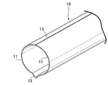
図1において,本発明の第1実施例の製造方法で製造される閉断面構造体10は,基本形を円筒形とするパイプ状をなしている。この閉断面構造体10は,開放面を互いに対向させる左右一対の半円筒状の閉断面構造体半部11,11と,これら閉断面構造体半部11,11の下端同士を一体に連結する,外側に隆起した断面V字状の屈曲部12と,これら閉断面構造体半部11,11の上端同士を接合する溶接部13とで構成される。
In FIG. 1, a closed
上記閉断面構造体10の製造方法について,図2を参照しながら説明する。図2の(B)〜(E)の工程において,左側の図は加工装置を示し,右側の図はその加工装置で加工されたワークを示す。
A method for manufacturing the closed
先ず,図2(A)において,閉断面構造体10の素材として,金属平板15を用意する。
First, in FIG. 2A, a metal
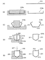
次に図2(B)の工程において,第1下型20及び第1上型21を使用して,上記金属平板15を第1半成品10aに成形する。第1下型20は,上面中央部の平坦部20aを間に挟んで,上面を開放した一対の半円筒状の凹部20b,20bを有し,また第1上型21は,上記平坦部20aに対応する平坦部21a,並びに上記凹部20b,20bに対応する一対の半円筒状の凸部21b,21bを下面に有している。而して,両型20,21間に金属平板15を挟んで両型20,21を閉じれば,平坦部12′の両側に上面を開放した一対の閉断面構造体半部11,11を連ねてなる第1半成品10aを成形することができる。その際,第1半成品10aでは,両閉断面構造体半部11,11の外端が平坦部12′と同一高さに並ぶことになる。
Next, in the process of FIG. 2 (B), the metal
次に図2(C)の工程において,第2下型22及び第2上型23を使用して,上記第1半成品10aを第2半成品10bに成形する。第2下型22には,平坦部22aを頂上とすると共に,その両端に連なる一対の下り斜面を凹状の円弧面22b,22bとした山部22Aが上面中央部に形成されており,この山部22Aの高さは,前記第1下型20の凹部20bの深さより遥かに小さく設定される。第2上型23には,上記山部22Aに対応する凹部23Aが形成されている。而して,両型22,23間に第1半成品10aを挟んで両型22,23を閉じれば,平坦部12′の両側に連なる一対の閉断面構造体半部11,11を起き上がらせた第2半成品10bを成形することができる。その結果,この第2半成品10bでは,閉断面構造体半部11,11の外端は,互いに近接しつゝ平坦部12′の上方へ移行することになる。
Next, in the step of FIG. 2C, the first
次に図2(D)の工程において,第3下型24及びパンチ25を使用して,上記第2半成品10bを第3半成品10cに成形する。第3下型24は,第2下型22の平坦部22aを,閉断面構造体10の屈曲部12に対応する断面V字状の凹溝24aに置き換えたものに相当し,パンチ25は,上記凹溝24aに対応する断面V字状の尖端部25aを有して,上下方向に延びる偏平な形状をなしている。而して,凹溝24a上に第2半成品10bの平坦部12′を載置し,その平坦部12′に向かってパンチ25を打ち下ろせば,その平坦部12′は,第3下型24の凹溝24aに押し込まれて断面V字状の屈曲部12に成形され,それに伴ない両閉断面構造体半部11,11が更に立ち上がった第3半成品10cを成形することができる。このとき,成形される上記屈曲部12の幅及び深さの設定により,両閉断面構造体半部11,11にはパンチ25を左右から挟みつける反りを発生させる。したがって,両閉断面構造体半部11,11からパンチ25を引き上げれば,両閉断面構造体半部11,11は,反りの復元力により外端同士を突き合わることができる。
Next, in the step of FIG. 2D, the second
最後に図2(E)の工程において,第3下型24又は適当な溶接作業台上で第3半成品10cを一対の押さえ治具26,26により左右から押さえて,両閉断面構造体半部11,11の外端同士の突き合わせ状態を確保し,その突き合わせ部を溶接トーチ27により溶接すれば,屈曲部12と溶接部13とを直径線上で対向させた前記閉断面構造体10を得ることができる。
Finally, in the step of FIG. 2 (E), the third
次に,図3及び図4に示す本発明の第2実施例について説明する。 Next, a second embodiment of the present invention shown in FIGS. 3 and 4 will be described.
図3において,本発明の第2実施例の製造方法で製造される閉断面構造体110は,基本形を四角柱とするものである。この閉断面構造体110は,開放面を互いに対向させる左右一対のチャンネル状の閉断面構造体半部111,111と,これら閉断面構造体半部111,111の下端同士を一体に連結する断面V字状の屈曲部112と,これら閉断面構造体半部111,111の上端同士を接合する溶接部113とで構成される。
In FIG. 3, the closed
上記閉断面構造体110の製造方法について,図4を参照しながら説明する。図4の(B)〜(F)の工程において,左側の図は加工装置を示し,右側の図はその加工装置で加工されたワークを示す。
A method for manufacturing the closed
先ず図4(A)において,閉断面構造体110の素材として,金属平板115を用意する。
First, in FIG. 4A, a metal
この金属平板115から図4(B)の工程で,頂部を平坦部112′とした断面台形の凸状部を中央に有する第1半成品110aを成形し,この第1半成品110aから図4(C)の工程で第2半成品110bを成形する。次いでこの第2半成品110bから図4(D)の第3工程で,平坦部112′の左右両端から一対のチャンネル状の閉断面構造体半部111,111を立ち上がらせた第3半成品110cを成形する。
In the process of FIG. 4B, a first
次に図4(E)において,前記第1実施例の場合と同様に,下型124の凹溝123a上に第3半成品110cの平坦部112′を載置し,その平坦部112′に向かってパンチ125を打ち下ろせば,その尖端部125aにより平坦部112′は,下型124の凹溝124aに押し込まれて断面V字状の屈曲部112に成形され,それに伴ない閉断面構造体半部111,111が更に立ち上がった第4半成品110dを成形することができる。このとき,成形される上記屈曲部112の幅及び深さの設定により,両閉断面構造体半部111,111にはパンチ125を左右から挟みつける反りを発生させる。したがって,両閉断面構造体半部111,111からパンチ125を引き上げれば,両閉断面構造体半部111,111は,反りの復元力により外端同士を突き合わることができる。
Next, in FIG. 4E, as in the case of the first embodiment, the
最後に図4(F)において,下型124又は適当な溶接作業台上で第3半成品110cを一対の押さえ治具126,126により左右から押さえて,両閉断面構造体半部111,111の外端同士の突き合わせ状態を確保し,その突き合わせ部を溶接トーチ127により溶接すれば,屈曲部112と溶接部113とを対向させた前記閉断面構造体110を得ることができる。
Finally, in FIG. 4 (F), the third
上記第2実施例の製造方法に従えば,図5〜図8に示すような閉断面構造体110をも製造することができる。尚,図5〜図8中,図3の閉断面構造体110と対応する部分には同一の参照符号を付すことにする。
If the manufacturing method of the said 2nd Example is followed, the
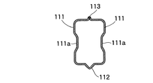
この閉断面構造体110は,開放面を互いに対向させる一対のチャンネル状の閉断面構造体半部111,111と,これら閉断面構造体半部111,111の一端同士を一体に連結するよう半径方向に隆起した断面V字状の屈曲部112と,これら閉断面構造体半部111,111の他端同士を接合する溶接部113とで構成される点では,前記第2実施例の閉断面構造体110と軌を一にするが,各閉断面構造体半部111,111は,その断面形状が閉断面構造体110の長手方向に沿って変化しており,且つ側面に凹状又は凸状の補強リブ111aが形成され,またこのリブ111aの幅広部には減量用の透孔111bが設けられている。
The
この閉断面構造体110は,素材の平板時に上記補強リブ111a及び透孔111bを形成し,その後,前記第2実施例と同様の工程を実行することで,製造されるものである。特に,断面V字状の屈曲部112を成形することにより,両閉断面構造体半部111,111を立ち上がらせるとき,各閉断面構造体半部111のリブ111aや透孔111bはパンチ等に干渉することがない。このことは,各閉断面構造体半部111に自由な形状を付与し得ることを意味する。
The
次に,図9及び図10に示す本発明の第3実施例について説明する。 Next, a third embodiment of the present invention shown in FIGS. 9 and 10 will be described.
図9において,この第3実施例の製造方法で製造される閉断面構造体210は,断面が野球のホームベース型をなす五角形のもので,開放面を互いに対向させる一対のアングル状の閉断面構造体半部211,211と,これら閉断面構造体半部211,211の一端同士を一体に連結する断面V字状の屈曲部212と,これら閉断面構造体半部211,211の他端同士を接合する溶接部213とで構成される。
In FIG. 9, a
上記閉断面構造体210の製造方法について,図10に基づいて説明する。図10の(B)〜(E)の工程において,左側の図は加工装置を示し,右側の図はその加工装置で加工されたワークを示す。
A method for manufacturing the
先ず,図10(A)において,閉断面構造体210の素材として,金属平板215を用意する。
First, in FIG. 10A, a metal
この金属平板215から図10(B)の工程で第1半成品210aを成形し,その第1半成品210aから図10(C)の工程において,平坦部212′の左右両端からアングル状の閉断面構造体半部211,211を立ち上がらせた第2半成品210bを成形する。
A first
次に図10Dにおいて,前記第1実施例の場合と同様に,下型224の凹溝224a上に第2半成品210bの平坦部212′を載置し,その平坦部212′に向かってパンチ225を打ち下ろせば,その尖端部225aにより平坦部212′は,下型224の凹溝224aに押し込まれて断面V字状の屈曲部212に成形され,それに伴ない閉断面構造体半部211,211が,反りによりパンチ225を左右から挟みつけるように立ち上がった第3半成品210cを成形することができる。
Next, in FIG. 10D, as in the case of the first embodiment, the flat portion 212 'of the second
両閉断面構造体半部211,211間からパンチ225を引き上げた後,最後に,図10(E)において,第3下型224a又は適当な溶接作業台上で第3半成品210を一対の押さえ治具226,226により左右から押さえて,両閉断面構造体半部211,211の外端同士の突き合わせ状態を確保し,その突き合わせ部を溶接トーチ227により溶接すれば,屈曲部212と溶接部213とを対向させた前記閉断面構造体210を得ることができる。
After the
次に,図11及び図12に示す本発明の第4実施例について説明する。 Next, a fourth embodiment of the present invention shown in FIGS. 11 and 12 will be described.
図11において,本発明の第4実施例の製造方法で製造される閉断面構造体310は,基本形を四角柱とし,それを三次元X,Y,Z方向に屈曲した形状をなすものである。この閉断面構造体310は,開放面を互いに対向させる一対のチャンネル状の閉断面構造体半部311,311と,これら閉断面構造体半部311,311の一端同士を一体に連結する断面V字状の屈曲部312と,これら閉断面構造体半部311,311の他端同士を接合する溶接部313とで構成され,上記閉断面構造体半部311,311の側壁の一方には凸部311aが,他方には凹部311bがそれぞれ形成されている。
In FIG. 11, a
上記閉断面構造体310の製造方法について,図12を参照しながら説明する。図12の(B)〜(G)の工程において,左側の図は加工装置を示し,右側の図はその加工装置で加工されたワークを示す。
A method for manufacturing the
先ず図12(A)において,閉断面構造体310の素材として,金属平板315を用意する。
First, in FIG. 12A, a metal
図12(B)の工程では,金属平板315から,頂部を平坦部312′とした断面台形の凸条部を中央に有する第1半成品310aを成形し,この第1半成品310aから図12(C)の工程で,平坦部312′を介して連結した左右一対のチャンネル状の閉断面構造体半部311,311を有する第2半成品310bを成形する。その際,閉断面構造体半部311,311には前記凸部311a及び凹部311bをそれぞれ成形する。
In the step of FIG. 12 (B), a first
この第2半成品310bの左右両端部にトリミングを施してから,これを図12(D)の工程に移し,平坦部312′付き凸条部の両端部を下型322の左右一対の凹溝322a,322aに載せた後,その両端部を上型323により上記凹溝322a,322aに押し込むことにより,閉断面構造体半部311,311を立ち上がらせた第3半成品310cを成形する。これまでの工程で第3半成品310cは,平坦部312′も,左右一対のチャンネル状の閉断面構造体半部311,311も三次元方向に屈曲した形状に成形される。
After trimming the left and right ends of the second
図12(E)の工程では,下型324の凹溝323a上に第4半成品310cの平坦部312′を載置し,その平坦部312′に向かって偏平パンチ325を打ち下ろす。この偏平パンチ325の尖端部325aも下型324の凹溝323aも平坦部312′に沿って三次元方向に屈曲している。したがって,平坦部312′は,下型324の凹溝324aに押し込まれて,三次元方向に屈曲した断面V字状の屈曲部312に成形され,それに伴ない閉断面構造体半部311,311が更に立ち上がった第4半成品310dを成形することができる。この場合も,成形される上記屈曲部312の幅及び深さの設定により,両閉断面構造体半部311,311にはパンチ325を左右から挟みつける反りを発生させる。したがって,両閉断面構造体半部311,311からパンチ325を引き上げれば,両閉断面構造体半部311,311は,反りの復元力により外端同士を突き合わることができる。
In the step of FIG. 12E, the
最後に図12(F)の第6工程において,下型324又は適当な溶接作業台上で第3半成品310cを一対の押さえ治具326,326により左右から押さえて,両閉断面構造体半部311,311の外端同士の突き合わせ状態を確保し,その突き合わせ部を溶接トーチ327により溶接すれば,屈曲部312と溶接部313とを対向させ,且つ三次元方向に屈曲した前記閉断面構造体310を得ることができる。
Finally, in the sixth step of FIG. 12 (F), the third
上記のように,何れの閉断面構造体10,110,210,310の製造に際しても,最終プレス工程では,半成品10b,110c,210b,310cの両閉断面構造体半部11,11;111,111;311,311;411,411の各間に挿入した偏平パンチ25,125,225,325により平坦部12′,112′,212′,312′を内側から押圧して屈曲部12,112,212,312を成形しながら両閉断面構造体半部11,11;111,111;211,211;311,311を,これらが偏平パンチ25,125,225,325を挟むように立ち上がらせるので,比較的小規模のプレス設備をもって,金属平板から各種形状の閉断面構造体10,110,210,310の全体形状を得ることができ,その後,両閉断面構造体半部11,11;111,111;211,211;311,311の外端同士を突き合わせて溶接することにより,所望の閉断面構造体10,110,210,310を得ることができる。したがって,金属平板15,115,215から用途に応じた各種所望形状の閉断面構造体10,110,210,310を簡単に製造することができ,製造コストの低減に寄与し得る。
As described above, in the production of any of the
また偏平パンチ25,125,225,325による屈曲部12,112,212,312の成形時には,両閉断面構造体半部11,11;111,111;211,211;311,311に反りを発生させ,この両閉断面構造体半部11,11;111,111;211,211;311,311の間から偏平パンチ25,125,225,325を引き上げたとき,両閉断面構造体半部11,11;111,111;211,211;311,311の外端を前記反りの復元力により互いに突き合わせるようにしたので,その外端相互の突き合わせを自然に行わせることができ,したがって次工程でその突き合わせ部の溶接を容易に且つ確実に行うことができる。
Further, when the
本発明は,上記実施例に限定されるものではなく,その要旨を逸脱しない範囲で種々の設計変更が可能である。例えば,断面V字状の屈曲部12,112,212,312には,応力集中を回避すべく適度の丸みを付すこともできる。
The present invention is not limited to the above embodiments, and various design changes can be made without departing from the scope of the invention. For example, the
10,110,210,310・・・閉断面構造体
10b,110c,210b,310c・・・半成品
11,111,211,311・・・閉断面構造体半部
12,112,212,312・・・屈曲部
12′,112′,212′,312′・・・平坦部
13,113,213,313・・・溶接部
15,115,215,315・・・金属平板
25,125,225,325・・・パンチ
10, 110, 210, 310 ...
Claims (2)
前記偏平パンチ(25,125,225,325)による前記隆起部(12,112,212,312)の成形時,前記両閉断面構造体半部(11,11;111,111;211,211;311,311)に反りを発生させ,この前記両閉断面構造体半部(11,11;111,111;211,211;311,311)の間から前記偏平パンチ(25,125,225,325)を引き上げたとき,前記両閉断面構造体半部(11,11;111,111;211,211;311,311)の外端を前記反りの復元力により互いに突き合わせることを特徴とする,閉断面構造体の製造方法。
In the manufacturing method of the closed section structure according to claim 1,
At the time of forming the raised portions (12, 112, 212, 312) by the flat punches (25, 125, 225, 325), the two closed cross-section structure halves (11, 11; 111, 111; 211, 211; 311, 311) is warped, and the flat punches (25, 125, 225, 325) are formed between the two closed-section structure halves (11, 11; 111, 111; 211, 211; 311, 311). ) Is pulled up, the outer ends of the two closed cross-section structures half portions (11, 11; 111, 111; 211, 211; 311, 311) are brought into contact with each other by the restoring force of the warp, A manufacturing method of a closed section structure.
Priority Applications (1)
| Application Number | Priority Date | Filing Date | Title |
|---|---|---|---|
| JP2004304011A JP4679108B2 (en) | 2004-10-19 | 2004-10-19 | Manufacturing method of closed cross-section structure |
Applications Claiming Priority (1)
| Application Number | Priority Date | Filing Date | Title |
|---|---|---|---|
| JP2004304011A JP4679108B2 (en) | 2004-10-19 | 2004-10-19 | Manufacturing method of closed cross-section structure |
Publications (2)
| Publication Number | Publication Date |
|---|---|
| JP2006116552A true JP2006116552A (en) | 2006-05-11 |
| JP4679108B2 JP4679108B2 (en) | 2011-04-27 |
Family
ID=36534926
Family Applications (1)
| Application Number | Title | Priority Date | Filing Date |
|---|---|---|---|
| JP2004304011A Expired - Fee Related JP4679108B2 (en) | 2004-10-19 | 2004-10-19 | Manufacturing method of closed cross-section structure |
Country Status (1)
| Country | Link |
|---|---|
| JP (1) | JP4679108B2 (en) |
Cited By (4)
| Publication number | Priority date | Publication date | Assignee | Title |
|---|---|---|---|---|
| JP2010247225A (en) * | 2008-11-06 | 2010-11-04 | Jfe Steel Corp | Method and apparatus for forming structure having closed cross section |
| WO2013179617A1 (en) | 2012-05-28 | 2013-12-05 | Jfeスチール株式会社 | Method of forming structure having closed cross section, and device for forming structure having closed cross section |
| WO2013179618A1 (en) | 2012-05-28 | 2013-12-05 | Jfeスチール株式会社 | Method of forming structure having closed cross section, and device for forming structure having closed cross section |
| CN105492136A (en) * | 2013-08-26 | 2016-04-13 | 杰富意钢铁株式会社 | Method for manufacturing curved component having polygonal closed-cross-sectional structure and curved component having polygonal closed-cross-sectional structure and manufactured using said method |
Citations (3)
| Publication number | Priority date | Publication date | Assignee | Title |
|---|---|---|---|---|
| JPS57165120A (en) * | 1981-04-03 | 1982-10-12 | Nissan Motor Co Ltd | Manufacture of bent pipe |
| JPH01162522A (en) * | 1987-12-18 | 1989-06-27 | Nakao Giken Kogyo:Kk | Forming method for corner round square cylindrical body |
| JPH1058040A (en) * | 1996-08-26 | 1998-03-03 | Toyota Motor Corp | Press forming method for member of hollow cross section |
-
2004
- 2004-10-19 JP JP2004304011A patent/JP4679108B2/en not_active Expired - Fee Related
Patent Citations (3)
| Publication number | Priority date | Publication date | Assignee | Title |
|---|---|---|---|---|
| JPS57165120A (en) * | 1981-04-03 | 1982-10-12 | Nissan Motor Co Ltd | Manufacture of bent pipe |
| JPH01162522A (en) * | 1987-12-18 | 1989-06-27 | Nakao Giken Kogyo:Kk | Forming method for corner round square cylindrical body |
| JPH1058040A (en) * | 1996-08-26 | 1998-03-03 | Toyota Motor Corp | Press forming method for member of hollow cross section |
Cited By (13)
| Publication number | Priority date | Publication date | Assignee | Title |
|---|---|---|---|---|
| JP2010247225A (en) * | 2008-11-06 | 2010-11-04 | Jfe Steel Corp | Method and apparatus for forming structure having closed cross section |
| KR20140148495A (en) | 2012-05-28 | 2014-12-31 | 제이에프이 스틸 가부시키가이샤 | Method of forming structure having closed cross section, and device for forming structure having closed cross section |
| WO2013179618A1 (en) | 2012-05-28 | 2013-12-05 | Jfeスチール株式会社 | Method of forming structure having closed cross section, and device for forming structure having closed cross section |
| JP2013244511A (en) * | 2012-05-28 | 2013-12-09 | Jfe Steel Corp | Method and device for forming structural body having closed section |
| JP2013244512A (en) * | 2012-05-28 | 2013-12-09 | Jfe Steel Corp | Method and device for forming structural body having closed section |
| KR20140148494A (en) | 2012-05-28 | 2014-12-31 | 제이에프이 스틸 가부시키가이샤 | Method of forming structure having closed cross section, and device for forming structure having closed cross section |
| WO2013179617A1 (en) | 2012-05-28 | 2013-12-05 | Jfeスチール株式会社 | Method of forming structure having closed cross section, and device for forming structure having closed cross section |
| US9630238B2 (en) | 2012-05-28 | 2017-04-25 | Jfe Steel Corporation | Method and apparatus that forms a closed cross-sectional structure |
| US9862017B2 (en) | 2012-05-28 | 2018-01-09 | Jfe Steel Corporation | Method and apparatus that forms a closed cross-sectional structure |
| US10160031B2 (en) | 2012-05-28 | 2018-12-25 | Jfe Steel Corporation | Method of forming a closed cross-sectional structure |
| CN105492136A (en) * | 2013-08-26 | 2016-04-13 | 杰富意钢铁株式会社 | Method for manufacturing curved component having polygonal closed-cross-sectional structure and curved component having polygonal closed-cross-sectional structure and manufactured using said method |
| US20160243603A1 (en) * | 2013-08-26 | 2016-08-25 | Jfe Steel Corporation | Method of producing polygonal closed cross-section structural component with a curved form and polygonal closed cross-section structural component produced by the method |
| US9981298B2 (en) * | 2013-08-26 | 2018-05-29 | Jfe Steel Corporation | Method of producing polygonal closed cross-section structural component with a curved form and polygonal closed cross-section structural component produced by the method |
Also Published As
| Publication number | Publication date |
|---|---|
| JP4679108B2 (en) | 2011-04-27 |
Similar Documents
| Publication | Publication Date | Title |
|---|---|---|
| KR101313887B1 (en) | Method and device for producing low-springback half shells and a h0llow profile consisting of two of such low-springback half shells | |
| JP3258470B2 (en) | Method of joining laminated metal sheets and joining tool set | |
| JP5433243B2 (en) | Square pipe, frame structure, square pipe manufacturing method, and square pipe manufacturing apparatus | |
| JP5454619B2 (en) | Closed-section structure forming method and closed-section structure forming apparatus | |
| GB1559186A (en) | Method of fabricating a bifurcated part of a cardan joint joint and apparatus for the performance thereof | |
| JP5966617B2 (en) | Closed-section structure forming method and closed-section structure forming apparatus | |
| JP5706042B2 (en) | Manufacturing method of hollow profile material with slit | |
| JP2017177594A (en) | Support and work, and configuration generating method of the support | |
| JP3114918B2 (en) | Manufacturing method of curved hollow pipe | |
| JP4679108B2 (en) | Manufacturing method of closed cross-section structure | |
| JP3863146B2 (en) | Grooving device for cutting blade | |
| JP6577955B2 (en) | How to adapt part shapes individually | |
| US20070033794A1 (en) | Method of producing honeycomb structure | |
| JP4446627B2 (en) | Punching device | |
| JP2007015016A (en) | Method for manufacturing metal plate having cambered hole | |
| JP2004337919A (en) | Laminated die | |
| JP2000326030A (en) | Method of manufacturing hollow member | |
| TWI480110B (en) | Method for manufacturing closed structure parts and apparatus for the same | |
| JP4949045B2 (en) | Metal fittings for wooden building components | |
| KR100730572B1 (en) | Manufacturing Method of Sandwich Type Panel and Manufacturing Metal Mold Set | |
| JP2016155167A (en) | Processing method of square columnar-body pipe | |
| JP2021178342A (en) | Joint fixing method and joint fixing structure of pipe diagonal material | |
| JP2020192567A (en) | Manufacturing method of bent article, and bent article | |
| JP2001219854A (en) | Hollow rack shaft, and manufacturing method therefor | |
| JP3800468B2 (en) | Method for producing hollow metal material |
Legal Events
| Date | Code | Title | Description |
|---|---|---|---|
| A621 | Written request for application examination |
Free format text: JAPANESE INTERMEDIATE CODE: A621 Effective date: 20070911 |
|
| A977 | Report on retrieval |
Free format text: JAPANESE INTERMEDIATE CODE: A971007 Effective date: 20100401 |
|
| A131 | Notification of reasons for refusal |
Free format text: JAPANESE INTERMEDIATE CODE: A131 Effective date: 20100915 |
|
| A521 | Request for written amendment filed |
Free format text: JAPANESE INTERMEDIATE CODE: A523 Effective date: 20101112 |
|
| RD03 | Notification of appointment of power of attorney |
Free format text: JAPANESE INTERMEDIATE CODE: A7423 Effective date: 20101112 |
|
| TRDD | Decision of grant or rejection written | ||
| A01 | Written decision to grant a patent or to grant a registration (utility model) |
Free format text: JAPANESE INTERMEDIATE CODE: A01 Effective date: 20110105 |
|
| A01 | Written decision to grant a patent or to grant a registration (utility model) |
Free format text: JAPANESE INTERMEDIATE CODE: A01 |
|
| A61 | First payment of annual fees (during grant procedure) |
Free format text: JAPANESE INTERMEDIATE CODE: A61 Effective date: 20110201 |
|
| R150 | Certificate of patent or registration of utility model |
Ref document number: 4679108 Country of ref document: JP Free format text: JAPANESE INTERMEDIATE CODE: R150 Free format text: JAPANESE INTERMEDIATE CODE: R150 |
|
| FPAY | Renewal fee payment (event date is renewal date of database) |
Free format text: PAYMENT UNTIL: 20140210 Year of fee payment: 3 |
|
| R250 | Receipt of annual fees |
Free format text: JAPANESE INTERMEDIATE CODE: R250 |
|
| R250 | Receipt of annual fees |
Free format text: JAPANESE INTERMEDIATE CODE: R250 |
|
| R250 | Receipt of annual fees |
Free format text: JAPANESE INTERMEDIATE CODE: R250 |
|
| R250 | Receipt of annual fees |
Free format text: JAPANESE INTERMEDIATE CODE: R250 |
|
| R250 | Receipt of annual fees |
Free format text: JAPANESE INTERMEDIATE CODE: R250 |
|
| R250 | Receipt of annual fees |
Free format text: JAPANESE INTERMEDIATE CODE: R250 |
|
| R250 | Receipt of annual fees |
Free format text: JAPANESE INTERMEDIATE CODE: R250 |
|
| R250 | Receipt of annual fees |
Free format text: JAPANESE INTERMEDIATE CODE: R250 |
|
| R250 | Receipt of annual fees |
Free format text: JAPANESE INTERMEDIATE CODE: R250 |
|
| LAPS | Cancellation because of no payment of annual fees |