JP2006103209A - Inkjet recording apparatus and recording method - Google Patents
Inkjet recording apparatus and recording method Download PDFInfo
- Publication number
- JP2006103209A JP2006103209A JP2004294278A JP2004294278A JP2006103209A JP 2006103209 A JP2006103209 A JP 2006103209A JP 2004294278 A JP2004294278 A JP 2004294278A JP 2004294278 A JP2004294278 A JP 2004294278A JP 2006103209 A JP2006103209 A JP 2006103209A
- Authority
- JP
- Japan
- Prior art keywords
- recording
- ink
- ejection
- scan
- discharge
- Prior art date
- Legal status (The legal status is an assumption and is not a legal conclusion. Google has not performed a legal analysis and makes no representation as to the accuracy of the status listed.)
- Granted
Links
Images


Abstract
Description
本発明は、例えば記録ヘッド等の記録手段により被記録材(記録媒体)へインクを吐出して画像を記録(印刷)するインクジェットプリンタなどのインクジェット記録装置に関する。 The present invention relates to an ink jet recording apparatus such as an ink jet printer that records (prints) an image by ejecting ink onto a recording material (recording medium) by recording means such as a recording head.
プリンタ、複写機、ファクシミリ等の機能を有する記録装置、あるいはコンピューターやワードプロセッサ等を含む複合型電子機器やワークステーションなどの出力機器として用いられる記録装置は、画像情報(文字情報等を含む)に基づいて用紙やプラスチック薄板等の被記録媒体に画像(文字等を含む)を記録していくように構成されている。なお、本明細書では、用紙等の印刷媒体上に文字や図形、写真等の画像をインクなどの色材(無色のコート材を含む場合もある。)で形成することを記録と呼ぶ。このような記録装置は、記録方式により、インクジェット式、ワイヤドット式、サーマル式、電子写真式等に分けることができる。これらの記録装置のうち、インクジェット式の記録装置(インクジェット記録装置)は、記録手段(記録ヘッド)から記録媒体にインクを吐出して記録を行うものであり、他の記録方式に比べて高精細化が容易でしかも高速で静粛性に優れ、かつ安価であるという優れた特徴を有する。インクジェット記録装置は、記録速度の向上のため、複数の記録素子を集積配列してなる記録ヘッドとして、インク吐出口(インク吐出部)及び液路を複数集積したものを用い、さらにカラー対応として、複数個の前記記録ヘッドを備えたものが一般的である。そしてこれら記録ヘッドは主走査方向に往復移動可能なキャリッジに載置される。そして主走査方向におおむね直交する方向に記録媒体が搬送可能に構成されている。 A recording device having functions such as a printer, a copying machine, a facsimile, or a recording device used as an output device such as a composite electronic device including a computer or a word processor or a workstation is based on image information (including character information). Thus, an image (including characters and the like) is recorded on a recording medium such as paper or a plastic thin plate. Note that in this specification, forming an image such as a character, graphic, or photograph on a print medium such as paper with a color material such as ink (which may include a colorless coating material) is referred to as recording. Such a recording apparatus can be classified into an ink jet type, a wire dot type, a thermal type, an electrophotographic type, and the like according to a recording method. Among these recording apparatuses, an ink jet recording apparatus (ink jet recording apparatus) performs recording by ejecting ink from a recording means (recording head) to a recording medium, and has higher definition than other recording systems. It has the excellent characteristics of being easy to make, high speed, excellent quietness, and inexpensive. In order to improve the recording speed, the ink jet recording apparatus uses a plurality of ink discharge ports (ink discharge portions) and a plurality of liquid paths integrated as a recording head in which a plurality of recording elements are integrated, Generally, a plurality of the recording heads are provided. These recording heads are placed on a carriage that can reciprocate in the main scanning direction. The recording medium can be conveyed in a direction substantially orthogonal to the main scanning direction.
記録開始前、ホームポジションにあるキャリッジは、記録開始命令がくると、主走査方向に移動しながら、記録ヘッド上の複数の吐出口から画像に応じてインクを吐出して記録を行う。ホームポジションとは反対側に位置する記録媒体端部まで画像を形成のための記録が終了するとキャリッジは元のホームポジションに戻り、再びキャリッジを主走査方向へ移動させつつ記録を繰り返す。このとき、ホームポジションへ戻るキャリッジの復方向への移動の際にも画像を形成することもある。この様にして記録媒体に記録を行っている際に、ある一定時間記録に使用されなかったインク吐出口から吐出を行うと、使用されていない間にインク吐出口からの溶媒等のインク成分の蒸発でインクの粘度が高くなり(これをインク増粘と呼ぶ。)、インク濃度の上昇や吐出不良が発生する。この現象を防止するために、一定時間が経過する毎にホームポジションにおいてインクの予備吐出や吸引など記録ヘッドの回復作業を実施している(例えば、特許文献1参照)。
一方、インクジェット記録装置における高画質化を達成するために、インク吐出口から吐出されるインク滴の大きさを小さくして画像の粒状感を低減させるというアプローチがある。インク滴を小さくすると吐出されるインク滴の量に対するインク吐出口からのインク蒸発量の占める割合が多くなる。そのため、インク増粘の速度が速くなりインク濃度の上昇や吐出不良が発生しやすくなった。そのため、インク滴を小さくした高画質のインクジェット記録装置では、記録ヘッドが一回の主走査を行う時間よりも短い時間でインク粘度が高くなり記録に適さなくなるという現象が発生した。このため、画像によっては、インク不吐出の許容時間(新鮮なインクが蒸発等により記録に適さなくなる程度に変質するまでの時間)を越えた時間不使用となる吐出口があるため、形成される画像の品質が低下することがあった。このような現象は、インク不吐出の許容時間が記録ヘッドの1回の走査時間よりも短いため、一回の走査毎に記録ヘッドの回復動作を行ったとしても防ぐことはできなかった。 On the other hand, in order to achieve high image quality in an inkjet recording apparatus, there is an approach of reducing the graininess of an image by reducing the size of ink droplets ejected from an ink ejection port. If the ink droplets are made smaller, the proportion of the amount of ink evaporated from the ink ejection port to the amount of ejected ink droplets increases. For this reason, the ink thickening speed is increased, and the ink density is increased and ejection failure is likely to occur. For this reason, in a high-quality inkjet recording apparatus in which ink droplets are reduced, a phenomenon has occurred in which the ink viscosity increases in a time shorter than the time for which the recording head performs one main scan, making it unsuitable for recording. For this reason, some images are formed because there are ejection openings that are not used for a time exceeding the allowable time for non-ejection of ink (the time until the fresh ink becomes unsuitable for recording due to evaporation or the like). The quality of the image sometimes deteriorated. Such a phenomenon cannot be prevented even if the recovery operation of the recording head is performed for each scanning because the allowable time of non-ejection of ink is shorter than the scanning time of one time of the recording head.
本発明は上記従来例に鑑みてなされたもので、シリアル方式の記録装置における記録ヘッドによる主走査に要する時間よりもインクの劣化時間が短い場合であっても、インク増粘による画像品質の低下を防止できるインクジェット記録装置及び記録方法を提供することを目的とする。 The present invention has been made in view of the above-described conventional example. Even when the ink deterioration time is shorter than the time required for the main scanning by the recording head in the serial recording apparatus, the image quality is deteriorated due to the ink thickening. An object of the present invention is to provide an ink jet recording apparatus and a recording method capable of preventing the above-described problem.
上記目的を達成するために本発明は以下の構成を備える。 In order to achieve the above object, the present invention comprises the following arrangement.
記録媒体に対して記録ヘッドを相対的に主走査させながら主走査方向とは異なる方向に並ぶ複数の吐出口からインクを吐出して記録媒体に記録する記録走査を行うインクジェット記録装置であって、
前記主走査方向について、前記記録ヘッドによる記録媒体に対する記録領域の両端外部において前記記録ヘッドによるインクの予備吐出が可能な予備吐出部と、 前記記録ヘッドの主走査方向に対する記録走査において、先にインクの吐出を行ってから次にインクの吐出を行うインク吐出間隔が所定値以内であるかを、前記記録ヘッドの各吐出口ごとに判定する判定手段と、
第1の記録走査では、前記判定手段によりインク吐出間隔が所定値以内と判定された吐出口を用いて記録を行い、第1の記録走査終了後、近傍に位置する前記予備吐出部において予備吐出を実施し、続く第2の記録走査では、前記第1の記録走査とは反対方向に走査して、前記判定手段によりインク吐出間隔が所定値以内ではないと判定された吐出口を用いて記録を行う記録制御手段とを備えることを特徴とする。
An inkjet recording apparatus that performs a recording scan in which ink is ejected from a plurality of ejection ports arranged in a direction different from the main scanning direction while performing a main scanning of the recording head relative to the recording medium, and recording on the recording medium.
In the main scanning direction, a preliminary ejection unit capable of preliminary ejection of ink by the recording head outside both ends of the recording area of the recording head by the recording head; Determining means for determining, for each discharge port of the recording head, whether or not an ink discharge interval at which ink is discharged next after discharge is within a predetermined value;
In the first recording scan, recording is performed using an ejection port whose ink ejection interval is determined to be within a predetermined value by the determination unit, and preliminary ejection is performed at the preliminary ejection unit located near the end of the first recording scan. In the subsequent second recording scan, scanning is performed in the direction opposite to that of the first recording scan, and recording is performed using the ejection port determined by the determination means that the ink ejection interval is not within a predetermined value. And a recording control means for performing the above.
あるいは、記録媒体に対して記録ヘッドを相対的に主走査させながら主走査方向とは異なる方向に並ぶ複数の吐出口からインクを吐出して記録媒体に記録する記録走査を行うインクジェット記録装置であって、
前記主走査方向について、前記記録ヘッドによる記録媒体に対する記録領域の両端外部において前記記録ヘッドによるインクの予備吐出が可能な予備吐出部と、
前記記録ヘッドの主走査方向に対する記録走査において、先にインクの吐出を行ってから次にインクの吐出を行うインク吐出間隔が所定値以内であるかを、前記記録ヘッドの各吐出口ごとに判定する判定手段と、
第1の記録走査では、前記判定手段により前記インク吐出間隔が所定値以内と判定された吐出口を用いて記録を行い、第1の記録走査終了後、前記予備吐出部において予備吐出を実施し、第2の記録走査では、前記記録ヘッドを前記第1の記録走査よりも高速に移動させてから、前記判定手段により前記インク吐出間隔が所定値以内ではないと判定された吐出口を用いて記録を行う記録制御手段とを備えることを特徴とする。
Alternatively, an inkjet recording apparatus that performs a recording scan in which ink is ejected from a plurality of ejection ports arranged in a direction different from the main scanning direction while the recording head is relatively scanned with respect to the recording medium. And
A preliminary ejection unit capable of preliminary ejection of ink by the recording head outside both ends of a recording area of the recording head with respect to the recording medium by the main scanning direction;
In the recording scan in the main scanning direction of the recording head, it is determined for each ejection port of the recording head whether the ink ejection interval at which ink is ejected first and then the ink is ejected next is within a predetermined value. Determination means to perform,
In the first recording scan, recording is performed using the ejection port in which the ink ejection interval is determined to be within a predetermined value by the determination unit, and after the first recording scan is completed, preliminary ejection is performed in the preliminary ejection unit. In the second recording scan, the recording head is moved at a speed higher than that of the first recording scan, and then the determination unit is used to determine that the ink discharge interval is not within a predetermined value. And a recording control means for performing recording.
本発明によれば、シリアル方式の記録装置における記録ヘッドによる主走査に要する時間よりも、新鮮なインクが記録に適さなくなる程度に変質するまでのインク不吐出の許容時間の方が短い場合であっても、インク増粘による画像品質の低下を防止できるという効果を奏する。 According to the present invention, the allowable time for non-ejection of ink until the quality of the ink becomes unsuitable for recording is shorter than the time required for the main scanning by the recording head in the serial recording apparatus. However, there is an effect that the deterioration of the image quality due to the ink thickening can be prevented.
また、記録走査中に、インク吐出間隔がインク不吐出の許容時間よりも開いてしまうような画像の記録時には、インク特性が劣化している可能性がある吐出口は使用せずにいったん記録し、インク特性が劣化している可能性がある吐出口については、インク不吐出の許容時間内に画像を記録できるように再走査して画像を形成する。 Also, during recording scanning, when recording an image where the ink discharge interval is longer than the ink non-discharge allowable time, the recording is temporarily performed without using the discharge port that may have deteriorated ink characteristics. For the ejection port where the ink characteristics may be deteriorated, an image is formed by rescanning so that the image can be recorded within the ink non-ejection allowable time.
[第1の実施形態]
以下、図面を参照して本発明の実施形態を詳細に説明する。以下に説明する実施形態では、インクジェット方式に従う記録ヘッドを用いた記録装置を例に挙げて説明する。
[First Embodiment]
Hereinafter, embodiments of the present invention will be described in detail with reference to the drawings. In the embodiment described below, a recording apparatus using a recording head according to an ink jet method will be described as an example.
この明細書において、「記録」(「プリント」という場合もある)とは、文字、図形等有意の情報を形成する場合のみならず、有意無意を問わず、また人間が視覚で知覚し得るように顕在化したものであるか否かを問わず、広く記録媒体上に画像、模様、パターン等を形成する、または媒体の加工を行う場合も表すものとする。 In this specification, “recording” (sometimes referred to as “printing”) is not only for forming significant information such as characters and graphics, but also for human beings to be perceived visually, regardless of significance. Regardless of whether or not it has been manifested, it also represents a case where an image, a pattern, a pattern or the like is widely formed on a recording medium or the medium is processed.
また、「記録媒体」とは、一般的な記録装置で用いられる紙のみならず、広く、布、プラスチック・フィルム、金属板、ガラス、セラミックス、木材、皮革等、インクを受容可能なものも表すものとする。 “Recording medium” refers not only to paper used in general recording apparatuses but also widely to cloth, plastic film, metal plate, glass, ceramics, wood, leather, and the like that can accept ink. Shall.
さらに、「インク」(「液体」と言う場合もある)とは、上記「記録(プリント)」の定義と同様広く解釈されるべきもので、記録媒体上に付与されることによって、画像、模様、パターン等の形成または記録媒体の加工、或いはインクの処理(例えば記録媒体に付与されるインク中の色剤の凝固または不溶化)に供され得る液体を表すものとする。 Furthermore, “ink” (sometimes referred to as “liquid”) is to be interpreted broadly in the same way as the definition of “recording (printing)” above. It represents a liquid that can be used for forming a pattern or the like, processing a recording medium, or processing an ink (for example, solidification or insolubilization of a colorant in ink applied to the recording medium).
またさらに、「ノズル」とは、特にことわらない限り吐出口ないしこれに連通する液路およびインク吐出に利用されるエネルギーを発生する素子を総括して言うものとする。 Furthermore, unless otherwise specified, the “nozzle” collectively refers to an ejection port or a liquid channel communicating with the ejection port and an element that generates energy used for ink ejection.
<インクジェット記録装置の説明(図10)>
図10は本発明の代表的な実施形態であるインクジェット記録装置1の構成の概要を示す外観斜視図である。図10に示すように、インクジェット記録装置(以下、記録装置という)は、インクジェット方式に従ってインクを吐出して記録を行なう記録ヘッド3を搭載したキャリッジ2にキャリッジモータM1によって発生する駆動力を伝達機構4より伝え、キャリッジ2を矢印A方向に往復移動させるとともに、例えば、記録紙などの記録媒体Pを給紙機構5を介して給紙し、記録位置まで搬送し、その記録位置において記録ヘッド3から記録媒体Pにインクを吐出することで記録を行なう。
<Description of Inkjet Recording Apparatus (FIG. 10)>
FIG. 10 is an external perspective view showing an outline of the configuration of the ink jet recording apparatus 1 which is a typical embodiment of the present invention. As shown in FIG. 10, an ink jet recording apparatus (hereinafter referred to as a recording apparatus) transmits a driving force generated by a carriage motor M1 to a
また、記録ヘッド3の状態を良好に維持するためにキャリッジ2を回復装置10の位置まで移動させ、間欠的に記録ヘッド3の吐出回復処理を行う。また、本実施形態の記録装置は、回復装置10のあるホームポジション以外に予備吐出が可能な予備吐出位置23を、キャリッジによる記録走査範囲内で、かつ、記録媒体に対する記録領域を挟んで回復装置10の反対側端部に設けている。これによって、予備吐出位置23において、回復動作(予備吐出)を行うことができる。なお、図10では予備吐出位置23を最大サイズの記録媒体の外側端部に設けた。しかし、記録ヘッド3の吐出口に対向する幅で、キャリッジ2の動作範囲全体にわたって予備吐出可能にたとえばインク吸収材等を配しておくこともできる。こうすることで、記録対象の記録媒体の幅が、最大の幅に比べて短い場合であっても、記録媒体の直近外側を予備吐出位置として予備吐出を行うことができる。なお予備吐出とは、記録ヘッド内部のインクを、記録目的ではなく新鮮なインクの再充填を目的として画像の形成に寄与しないインク滴を吐出することであり、吐出口に対応するインク受けが設けられた予備吐出位置で実行される。
Further, in order to maintain the state of the
記録装置1のキャリッジ2には記録ヘッド3を搭載するのみならず、記録ヘッド3に供給するインクを貯留するインクカートリッジ6を装着する。インクカートリッジ6はキャリッジ2に対して着脱自在になっている。
In addition to mounting the
図10に示した記録装置1はカラー記録が可能であり、そのためにキャリッジ2にはマゼンタ(M)、シアン(C)、イエロー(Y)、ブラック(K)のインクを夫々、収容した4つのインクカートリッジを搭載している。これら4つのインクカートリッジは夫々独立に着脱可能である。
The recording apparatus 1 shown in FIG. 10 is capable of color recording. For this reason, the
さて、キャリッジ2と記録ヘッド3とは、両部材の接合面が適正に接触されて所要の電気的接続を達成維持できるようになっている。記録ヘッド3は、記録信号に応じてエネルギーを印加することにより、複数の吐出口からインクを選択的に吐出して記録する。特に、この実施形態の記録ヘッド3は、熱エネルギーを利用してインクを吐出するインクジェット方式を採用し、熱エネルギーを発生するために電気熱変換体を備え、その電気熱変換体に印加される電気エネルギーが熱エネルギーへと変換され、その熱エネルギーをインクに与えることにより生じる膜沸騰による気泡の成長、収縮によって生じる圧力変化を利用して、吐出口よりインクを吐出させる。この電気熱変換体は各吐出口のそれぞれに対応して設けられ、記録信号に応じて対応する電気熱変換体にパルス電圧を印加することによって対応する吐出口からインクを吐出する。
Now, the
図10に示されているように、キャリッジ2はキャリッジモータM1の駆動力を伝達する伝達機構4の駆動ベルト7の一部に連結されており、ガイドシャフト13に沿って矢印A方向に摺動自在に案内支持されるようになっている。従って、キャリッジ2は、キャリッジモータM1の正転及び逆転によってガイドシャフト13に沿って往復移動する。また、キャリッジ2の移動方向(矢印A方向)に沿ってキャリッジ2の絶対位置を示すためのスケール8が備えられている。この実施形態では、スケール8は透明なPETフィルムに必要なピッチで黒色のバーを印刷したものを用いており、その一方はシャーシ9に固着され、他方は板バネ(不図示)で支持されている。
As shown in FIG. 10, the
また、記録装置1には、記録ヘッド3の吐出口(不図示)が形成された吐出口面に対向してプラテン(不図示)が設けられており、キャリッジモータM1の駆動力によって記録ヘッド3を搭載したキャリッジ2が往復移動されると同時に、記録ヘッド3に記録信号を与えてインクを吐出することによって、プラテン上に搬送された記録媒体Pの全幅にわたって記録が行われる。
Further, the recording apparatus 1 is provided with a platen (not shown) facing the discharge port surface where the discharge port (not shown) of the
さらに、図10において、14は記録媒体Pを搬送するために搬送モータM2によって駆動される搬送ローラ、15はバネ(不図示)により記録媒体Pを搬送ローラ14に当接するピンチローラ、16はピンチローラ15を回転自在に支持するピンチローラホルダ、17は搬送ローラ14の一端に固着された搬送ローラギアである。そして、搬送ローラギア17に中間ギア(不図示)を介して伝達された搬送モータM2の回転により、搬送ローラ14が駆動される。
Further, in FIG. 10, 14 is a transport roller driven by a transport motor M2 to transport the recording medium P, 15 is a pinch roller that abuts the recording medium P against the
またさらに、20は記録ヘッド3によって画像が形成された記録媒体Pを記録装置外ヘ排出するための排出ローラであり、搬送モータM2の回転が伝達されることで駆動されるようになっている。なお、排出ローラ20は記録媒体Pをバネ(不図示)により圧接する拍車ローラ(不図示)により当接する。22は拍車ローラを回転自在に支持する拍車ホルダである。
Further,
またさらに、記録装置1には、図10に示されているように、記録ヘッド3を搭載するキャリッジ2の記録動作のための往復運動の範囲外(記録領域外)の所望位置(例えば、ホームポジションに対応する位置)に、記録ヘッド3からの吐出状態を良好に保つための回復動作を行う回復装置10が配設されている。
Furthermore, as shown in FIG. 10, the recording apparatus 1 includes a desired position (for example, a home position) outside the reciprocal movement range (outside the recording area) for the recording operation of the
回復装置10は、記録ヘッド3の吐出口面をキャッピングするキャッピング機構11と記録ヘッド3の吐出口面をクリーニングするワイピング機構12を備えており、キャッピング機構11による吐出口面のキャッピングに連動して回復装置内の吸引手段(吸引ポンプ等)により吐出口からインクを強制的に排出させ、それによって、記録ヘッド3のインク流路内の粘度の増したインクや気泡等を除去するなどの吐出回復処理を行う。もちろん、記録ヘッド3を回復装置10の位置に移動して予備吐出を行うこともできる。
The
また、非記録動作時等には、記録ヘッド3の吐出口面をキャッピング機構11によるキャッピングする(キャップを吐出口面に当接させる)ことによって、記録ヘッド3を保護するとともにインクの蒸発や乾燥を防止することができる。一方、ワイピング機構12はキャッピング機構11の近傍に配され、記録ヘッド3の吐出口面に付着したインク液滴やほこりなどの汚れを拭き取るようになっている。これらキャッピング機構11及びワイピング機構12により、記録ヘッド3のインク吐出状態を正常に保つことが可能となっている。
Further, during a non-recording operation or the like, the ejection head surface of the
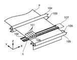
図1は記録ヘッドで記録紙面上を記録していく際のプリンタ部の構成を模式的に示したものである。模式的に示したために、図10の構成とは若干相違する点もあるが、記録原理を見やすくするためのものであり、発明の本質に影響を及ぼすものではない。図1において、101はインクカートリッジである。これらは、4色のカラーインク、ブラック、シアン、マゼンタ、イエローがそれぞれ詰め込まれたインクタンクと、それぞれの色のインクを吐出する吐出口列を備えた記録ヘッド102により構成されている。
FIG. 1 schematically shows a configuration of a printer unit when recording on a recording sheet with a recording head. Since it is schematically shown, there are some differences from the configuration of FIG. 10, but it is intended to make the recording principle easier to see and does not affect the essence of the invention. In FIG. 1,
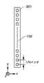
この記録ヘッド上に配列する吐出口の様子を図1のZ方向から示したものが図2である。201は記録ヘッド102上に複数配列された吐出口である。吐出口の間隔は図2では1/Nインチ(約1/2.5Nセンチメートル)であるが、実際の記録装置ではN=300あるいは600程度である。記録ヘッド102には、図2に示すような複数の吐出口が配列された吐出口列を複数備えており、それぞれの吐出口列から複数種類のインクを吐出させる。図1に戻ると、103は紙送りローラで104の補助ローラとともに記録媒体Pを抑えながら図の矢印の方向に回転し、記録媒体PをY方向に随時送っていく。また105は給紙ローラであり記録媒体Pの給紙を行うとともに、103、104と同様、記録媒体Pを抑える役割も果たす。106は4つのインクカートリッジを支持し、記録とともにこれらを移動させるキャリッジである。これは記録を行っていないとき、あるいは記録ヘッドの回復作業などを行うときには図の点線で示した位置のホームポジションhに待機するようになっている。そしてホームポジションh付近に回復装置が配置されており、記録媒体を挟んで反対側に予備吐受け部を備える予備吐出位置107が設けられている。
FIG. 2 shows the state of the discharge ports arranged on the recording head from the Z direction in FIG.
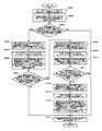
<記録装置の制御構成(図3)>
図3は、本発明の一実施形態に係る図1及び図10のインクジェット記録装置の制御構成を示すブロック図である。図3の構成は、メインバスライン305に対して夫々アクセスする画像入力部303、それに対応する画像信号処理部304、中央制御部CPU300といったソフト系処理手段と、操作部306、回復系制御回路307、ヘッド温度制御回路314、ヘッド駆動制御回路315、主走査方向へのキャリッジ駆動制御回路316、副走査方向への紙送り制御回路317といったハード系処理手段とに大別される。
<Control Configuration of Recording Apparatus (FIG. 3)>
FIG. 3 is a block diagram showing a control configuration of the ink jet recording apparatus of FIGS. 1 and 10 according to an embodiment of the present invention. 3 includes software processing means such as an
CPU300は、通常ROM(リードオンリメモリ)301とRAM(ランダムアクセスメモリ)302を有し、入力情報に対して適正な記録条件を与えて記録ヘッド313を駆動して記録を行う。又、RAM302内には、記録ヘッドの回復シーケンスを実行するプログラムがあらかじめ格納されており、必要に応じて予備吐出条件等の回復条件(タイミングや位置など)を回復系制御回路307に伝えることで、CPU300はキャリッジ駆動制御回路316や記録ヘッド313、保温ヒータ等を制御する。また、RAM302には後述する、記録走査の際に吐出間隔が吐出許容間隔以上となる吐出口が存在するか否かを示す情報を記憶する。この情報は、それぞれの吐出口ごとに記憶してもよく、また所定数の吐出口を1つのグループとして、そのグループ内に吐出間隔が吐出許容間隔以上となる吐出口が存在するか否かを示す情報を記憶してもよい。回復系モータ308は、前述したような記録ヘッド313とこれに対向離間するクリーニングブレード309やキャップ310、吸引ポンプ311を駆動する。ヘッド駆動制御回路315は、記録ヘッド313のインク吐出用電気熱変換体の駆動条件を実行するもので、通常予備吐出や記録用インク吐出を記録ヘッド313に行わせる。
The
一方、記録ヘッド313のインク吐出用の電気熱変換体が設けられているヘッド基板には、保温ヒータが設けられている場合もあり、記録ヘッド内のインク温度を所望設定温度に加熱調整することができる。又、ダイオードセンサ312は、同様にヘッド基板に設けられているもので、実質的な記録ヘッド内部のインク温度を測定するためのものである。ダイオードセンサ312も同様に、基板にではなく外部に設けられていても良く記録ヘッドの周囲近傍にあっても良い。
<本発明の記録動作>
以上の装置構成に基づく、本発明の第1の実施形態について以下に説明する。本発明の第1の実施形態では、図2に示したインク吐出口列が一列で構成された記録ヘッドを4つ備え、各記録ヘッドはブラック、シアン、マゼンタ、イエローのインクを吐出する。各記録ヘッドは、吐出口数L=256個で、吐出口の間隔が1/600インチ(約1/240センチメートル)として記録画素密度が600dpi(約240ドット/センチメートル)になるように構成されている。また、各記録ヘッドからの吐出量は、1滴あたり約2plのインク滴が吐出可能なように構成されており、このインク滴を安定して吐出するための吐出周波数は、24KHzとなっている。この記録ヘッドを搭載したキャリッジの主走査方向への速度は、主走査方向にインク滴を1200dpi(約480ドット/センチメートル)の密度で記録すると、20インチ/秒(約50センチメートル/秒)となる。
On the other hand, a heat retention heater may be provided on the head substrate on which the electrothermal transducer for ink ejection of the
<Recording Operation of the Present Invention>
A first embodiment of the present invention based on the above apparatus configuration will be described below. In the first embodiment of the present invention, four recording heads each having one ink discharge port array shown in FIG. 2 are provided, and each recording head discharges black, cyan, magenta, and yellow ink. Each recording head is configured so that the number of ejection ports is L = 256, the interval between ejection ports is 1/600 inch (about 1/240 cm), and the recording pixel density is 600 dpi (about 240 dots / cm). ing. Further, the ejection amount from each recording head is configured so that about 2 pl of ink droplets can be ejected per droplet, and the ejection frequency for stably ejecting these ink droplets is 24 KHz. . The speed in the main scanning direction of the carriage equipped with this recording head is 20 inches / second (about 50 centimeters / second) when ink droplets are recorded at a density of 1200 dpi (about 480 dots / cm) in the main scanning direction. It becomes.
本発明の第1の実施形態においては、図1のホームポジション(h)の位置と記録媒体を介して対向する位置に記録に使用しないインク滴を受ける予備吐出位置107を設けている。記録媒体の主走査方向の長さは8インチ(約20センチメートル)とする。
In the first embodiment of the present invention, a
図4は、本実施形態の記録装置において、インクをある吐出口から吐出して再度吐出するまでの時間(吐出間隔)とインク吐出状態との関係を示した図である。インク吐出状態において、「×」がインク増粘の影響によりインク滴の着弾位置の乱れやインク濃度上昇による色味の変化が発生する状態、「△」がインク滴の着弾位置の乱れは発生しないがインク濃度の上昇により少し色味が変化する状態、「○」がインク滴の着弾位置の乱れやインク濃度の上昇による色味の変化が発生しない状態を示している。図4よりインク吐出間隔が0.6(秒)以上あると「×」、0.5(秒)で「△」、0.4(秒)以下だと「○」となることがわかる。そこで、本実施形態では、インク吐出間隔の上限を0.4秒とするように画像記録を制御する。このインク吐出間隔の上限を吐出許容間隔と呼ぶことにする。なお、図4は、本実施形態の記録装置で用いるインクの特性に基づいた一例であり、本実施形態とインクの組成が異なったり、あるいは記録ヘッドの構造が異なれば、図4とは相違する表となる。しかし、吐出許容間隔がこのインク特性と吐出許容間隔との対応表から与えられる点は同様である。 FIG. 4 is a diagram showing the relationship between the time (ejection interval) from the time when ink is ejected from a certain ejection port to the time of ejection again and the ink ejection state in the recording apparatus of the present embodiment. In the ink ejection state, “×” indicates a state in which the ink droplet landing position is disturbed due to the effect of ink thickening or a color change occurs due to an increase in ink density, and “△” indicates that the ink droplet landing position is not disturbed. Indicates a state in which the color changes slightly due to an increase in ink density, and “◯” indicates a state in which the landing position of the ink droplet does not change and the color does not change due to an increase in ink density. It can be seen from FIG. 4 that the ink discharge interval is 0.6 (seconds) or more, “×”, 0.5 (seconds) “Δ”, and 0.4 (seconds) or less “◯”. Therefore, in this embodiment, image recording is controlled so that the upper limit of the ink discharge interval is 0.4 seconds. The upper limit of this ink discharge interval is called the discharge allowable interval. FIG. 4 is an example based on the characteristics of the ink used in the recording apparatus of the present embodiment, and differs from FIG. 4 if the ink composition is different from that of the present embodiment or the structure of the recording head is different. It becomes a table. However, the point that the allowable discharge interval is given from the correspondence table between the ink characteristics and the allowable discharge interval is the same.
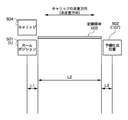
図5は、本実施形態におけるキャリッジが走査する位置関係を示した図である。ホームポジション501(図1のホームポジションh)の位置から記録媒体503の端部までの1インチの距離L1をキャリッジが走査するのに要するキャリッジの立ち上がり時間は0.15(秒)である。記録媒体503の主走査方向の長さL2(本例では8インチ)をキャリッジが走査するのに要する時間は、20インチ/秒の速度で記録を行うと、8(インチ)/20(インチ/秒)=0.4(秒)となる。記録媒体503の端部から予備吐出位置502までの1インチの距離L3をキャリッジが走査するのに要するキャリッジの立ち下がり時間は0.15(秒)である。
FIG. 5 is a diagram showing the positional relationship that the carriage scans in the present embodiment. The carriage rising time required for the carriage to scan a distance L1 of 1 inch from the position of the home position 501 (home position h in FIG. 1) to the end of the
図4に示した、前回吐出してから吐出するまでの時間(吐出間隔)と吐出状態の関係より、吐出間隔が0.4(秒)以内でないと形成される画像品質の低下(あるいは劣化)を引き起こす。したがって、ホームポジション501において予備吐出を実施して主走査方向に記録を開始したとしても、記録媒体503の領域を走査し終わるのに0.15(秒)+0.4(秒)=0.55(秒)必要となる。このため、記録媒体の主走査方向の後半部分にだけ画像データがあるインク吐出口、すなわち予備吐出してから吐出間隔が吐出許容間隔以上開くような吐出口においては吐出不良を引き起こしてしまう。具体的には、記録媒体のホームポジション501側端部から0.4−0.15(秒)=0.25秒以内に最初のインク滴を吐出できないと、吐出不良の可能性がある。つまり20(インチ/秒)×0.4−0.15(秒)=5インチ(約12.5センチメートル)の位置までが、予備吐出から吐出許容間隔内に記録可能である。
From the relationship between the discharge time from the previous discharge shown in FIG. 4 (discharge interval) and the discharge state, the quality (or deterioration) of the formed image is reduced unless the discharge interval is within 0.4 (seconds). cause. Therefore, even if preliminary ejection is performed at the
なお、本実施形態では、記録媒体の幅は8インチでキャリッジの移動時間に換算して0.4秒に相当する。すなわちキャリッジの走査開始側の記録媒体の端部でインク吐出していれば、その走査においてキャリッジが他方の端部に到達するのが0.4秒後であるため、その間インクを吐出しなかったとしても吐出許容間隔に納まる。このため、吐出間隔として考慮すべきは予備吐出後の吐出間隔に限られる。記録時のインク吐出間隔が吐出許容間隔を越える場合は、第3実施形態で説明する。 In the present embodiment, the width of the recording medium is 8 inches, which corresponds to 0.4 seconds in terms of carriage movement time. That is, if ink is ejected at the end of the recording medium on the scanning start side of the carriage, the carriage reaches the other end in the scanning after 0.4 seconds, so no ink was ejected during that time. Even within the allowable discharge interval. For this reason, the discharge interval to be considered is limited to the discharge interval after the preliminary discharge. The case where the ink discharge interval during recording exceeds the allowable discharge interval will be described in a third embodiment.
図6は、本実施形態における記録動作を説明する図である。また、図7は、本実施形態における記録動作を説明するフローチャートである。図7のフローチャートは、記録装置制御するCPU300により実行される制御手順である。また、その制御手順をCPU300に実行させるためのプログラムの手順でもある。図7に示すフローチャートでは、図6のホームポジション601の位置から記録ヘッドを搭載したキャリッジ(不図示)の走査を開始して、画像領域Aを最短では1パスで記録する記録動作について説明を行う。本明細書で画像領域とは1回の記録ヘッドによる走査で記録媒体に画像が記録される領域をいう。
FIG. 6 is a diagram for explaining a recording operation in the present embodiment. FIG. 7 is a flowchart for explaining the recording operation in the present embodiment. The flowchart in FIG. 7 is a control procedure executed by the
図7のステップS701において、まずキャリッジをホームポジションに移動して、各色の吐出口数256個の全ての吐出口から予備吐出を実施する。次にステップS702において、記録に使用する各吐出口に対して、ステップS701で予備吐出を実施してから画像領域Aの画像データの記録が開始されるまでの時間が所定時間(吐出許容間隔)以内、たとえば0.4秒以内かどうかの判断を行う。すべての吐出口について条件が満たされていればステップS703に分岐する。ひとつでも条件を満たさない吐出口があればステップS705に分岐する。ステップS705に分岐する場合には、条件を満たすと判定された吐出口と、条件を満たさないと判定された吐出口をそれぞれ識別可能に記憶しておく。 In step S701 in FIG. 7, the carriage is first moved to the home position, and preliminary ejection is performed from all of the 256 ejection ports for each color. Next, in step S702, the time from the start of preliminary ejection in step S701 to the start of image data recording in the image area A for each ejection port used for recording is a predetermined time (discharge allowable interval). Within, for example, 0.4 seconds. If the conditions are satisfied for all the discharge ports, the process branches to step S703. If even one discharge port does not satisfy the condition, the process branches to step S705. When branching to step S705, the discharge port determined to satisfy the condition and the discharge port determined not to satisfy the condition are stored in an identifiable manner.
ステップS702では、これから行おうとする1回の走査で記録される画像領域A(注目画像領域と呼ぶ。)の各色成分毎のビットマップデータに基づいて、最初のインク吐出が、記録媒体端部の記録を行うはずのタイミングから0.25秒以上経過していれば「No」と判定する。0.25秒は、画素数に換算すると、24000(Hz)×0.25(秒)=6000ドットとなる。したがって、画像データから、ステップS702の判定は、最初に記録されるドットがホームポジション側の記録媒体端部に相当するドットから6000ドット以上離れていないか判定することで実現できる。このように、時間をドット位置に換算してステップS702の判定を行うことができる。このようなS702の判定を記録ヘッドの複数の吐出口全てに対して行う。 In step S702, based on the bitmap data for each color component of the image area A (referred to as a target image area) to be recorded in one scan to be performed, the first ink ejection is performed at the edge of the recording medium. If 0.25 seconds or more have elapsed from the timing at which recording is to be performed, “No” is determined. When converted into the number of pixels, 0.25 seconds is 24000 (Hz) × 0.25 (seconds) = 6000 dots. Therefore, the determination in step S702 can be realized from the image data by determining whether or not the first recorded dot is more than 6000 dots away from the dot corresponding to the end of the recording medium on the home position side. In this way, the determination in step S702 can be performed by converting the time into a dot position. Such determination of S702 is performed for all of the plurality of ejection openings of the recording head.
ステップS702の判断において「Yes」の場合だと、いずれの吐出口についても吐出間隔が吐出許容間隔以上あくことはない。そこでステップS703において、記録に使用する全ての吐出口を用いて画像領域Aの記録を完成させる。そして、ステップS704において復路方向にキャリッジを移動させてキャリッジをホームポジションに戻す。その後つぎの画像領域である図6の画像領域Bを記録するため、ステップS708において記録媒体を256dot/600dpiの量、搬送する。 If “Yes” in the determination of step S702, the discharge interval does not exceed the discharge allowable interval for any of the discharge ports. Therefore, in step S703, the recording of the image area A is completed using all the ejection openings used for the recording. In step S704, the carriage is moved in the backward direction to return the carriage to the home position. Thereafter, in order to record the image area B of FIG. 6 as the next image area, the recording medium is conveyed by an amount of 256 dots / 600 dpi in step S708.
ステップS702の判断において「No」の場合だと、いずれかの吐出口について吐出間隔が吐出許容間隔以上あくものがある。そこで、ステップS705において、予備吐出から吐出許容間隔以内すなわち0.4秒以内に最初のインク吐出を行って画像データの記録を開始する吐出口のみを使用して、往路方向に画像領域Aを記録する。このとき使用される吐出口は、ステップS702の判定において記憶されたものである。 If “No” in the determination in step S702, there is a case where the discharge interval is longer than the discharge allowable interval for any of the discharge ports. Therefore, in step S705, the image area A is recorded in the forward direction using only the ejection port that starts the recording of the image data by performing the first ink ejection within the allowable ejection interval, that is, within 0.4 seconds from the preliminary ejection. To do. The discharge ports used at this time are those stored in the determination in step S702.
往路方向の記録が終わったなら、次にステップS706において、ホームポジションとは記録媒体を挟んで反対に位置する予備吐出位置602(図10の吐出位置23)で、各色の吐出口数256個の全ての吐出口から予備吐出を実施する。ステップS707において、ステップS705で使用しなかった吐出口を使用して、復路方向に画像領域Aを記録し完成させる。ステップS705で使用しなかった吐出口とは、ステップS702において予備吐出を実施した時間から画像領域Aの最初のインク吐出までの時間間隔が吐出許容間隔(たとえば0.4秒)以内でないと判定された吐出口である。往路で形成された部分(ライン)は復路では記録しない。
When the recording in the forward direction is completed, next, in step S706, all the 256 ejection openings for each color at the preliminary ejection position 602 (
その後、次の画像領域である図6の画像領域Bを記録するため、ステップS708において記録媒体を256dot/600dpiの量、搬送する。 Thereafter, in order to record the next image area, image area B in FIG. 6, the recording medium is conveyed by an amount of 256 dots / 600 dpi in step S708.
そして、図6の画像領域B、C、あるいはその他の画像領域に対しても画像領域Aと同様にステップS701からステップS708の工程を繰り返して画像を完成させる。 Then, for the image areas B and C in FIG. 6 or other image areas, the process from step S701 to step S708 is repeated as in the image area A to complete the image.
このように、前回の吐出である予備吐出を実施してから画像データを記録するまでの時間が画像劣化を引き起こす時間より長い吐出口に対しては、キャリッジの往路方向での走査では記録を行わずに、復路方向からの記録開始位置に位置する予備吐出位置にて予備吐出を実施した後、復路方向での走査において記録して画像を完成させることで、画像劣化を引き起こすことなく画像を完成させることができる。 As described above, for the ejection port in which the time from when the preliminary ejection as the previous ejection is performed to when the image data is recorded is longer than the time causing the image degradation, the recording is performed in the scanning in the forward direction of the carriage. The image is completed without causing image degradation by performing preliminary ejection at the preliminary ejection position located at the recording start position from the backward direction, and then recording in scanning in the backward direction to complete the image. Can be made.
本実施形態では、最小で1パス記録の場合について説明した。1パス方式では、1回のパスについて図7の手順が実行される。そのために1回のパスが往路と復路に分割記録されることもあり得る。マルチパス記録においても、その主走査で記録予定の画像データに関して本実施形態と同様の方法を用いることで画像劣化を防止できる。マルチパス記録とは、1つの画像領域を複数回の記録ヘッドによる走査で記録する方法である。マルチパスでは、通常1回の走査毎に所定量ずつ記録媒体が搬送されるが、本実施形態をマルチパスに適用すると、1回のパスについて図7の手順が実行される。そのために、1回のパスが往路と復路に分割記録されることもあり得る。その場合には往路と復路の間には記録媒体の搬送はおこなわない。 In the present embodiment, the case of one-pass printing at the minimum has been described. In the one-pass method, the procedure shown in FIG. 7 is executed for one pass. Therefore, one pass may be divided and recorded on the forward path and the backward path. Even in multi-pass printing, image degradation can be prevented by using a method similar to that of the present embodiment for image data to be printed in the main scanning. Multipass printing is a method of printing one image area by scanning with a plurality of printing heads. In the multi-pass, the recording medium is usually conveyed by a predetermined amount for each scanning, but when this embodiment is applied to the multi-pass, the procedure of FIG. 7 is executed for one pass. Therefore, one pass may be divided and recorded on the forward path and the backward path. In that case, the recording medium is not conveyed between the forward path and the backward path.
また、本実施形態では、往路方向を記録する場合にのみ画像を形成するための画像劣化を生じる吐出口の有無の検知を各吐出口に対して実施した片方向記録を基本にしていたが、これに限定されることはなく、往路方向の記録において画像領域を完成させることができたならば、復路方向においても次の画像領域の記録を行っても良い。その場合には復路方向の記録時に画像を形成するための画像劣化を生じる吐出の有無の検知を各吐出口に対しても実施して記録を行えばよい。このような構成とすることにより、往復記録を行うことで記録速度を向上させることができる。 Further, in the present embodiment, based on the one-way recording in which the detection of the presence or absence of the discharge ports that cause image deterioration for forming an image only when recording the forward direction is performed on each discharge port, The present invention is not limited to this, and if the image area can be completed in the forward direction recording, the next image area may be recorded in the backward direction. In that case, the recording may be performed by detecting the presence / absence of ejection that causes image deterioration for forming an image during recording in the backward direction also for each ejection port. With this configuration, the recording speed can be improved by performing reciprocal recording.
また、本実施形態では、前回の吐出を予備吐出として説明したが、これに限定されることはなく、前回の吐出を画像データの記録に使用した吐出として、次回の画像データ記録までに画像劣化を引き起こす時間より長い時間がかかる場合は、その走査での記録を行わずに予備吐出を実施後、反対方向からの記録走査で画像を完成させても良い。 In the present embodiment, the previous ejection is described as the preliminary ejection. However, the present invention is not limited to this, and the previous ejection is used as the ejection used for recording the image data. In the case where it takes longer than the time to cause the image, the image may be completed by the recording scan from the opposite direction after performing the preliminary ejection without performing the recording in the scanning.
<第1実施形態の変形例>
また、本実施形態では、図7のステップS702の実行による時間のロスをなくすために、画像の記録開始前にステップS702をまず実行しておき、その後、記録走査を行う際にステップS701をそれぞれ実行するように構成することもできる。こうすることで、予備吐出後、記録開始までの間において、ステップS702による時間の浪費を低減できる。このように、ステップS702の処理を画像の記録開始前にあらかじめ実行しておくことにより、記録装置の記録時のCPUの負荷を低減させることができる。さらには、記録装置に搭載するCPUを低価格のものとすることができるため、コスト削減が可能となる。
<Modification of First Embodiment>
Further, in the present embodiment, in order to eliminate time loss due to the execution of step S702 in FIG. 7, step S702 is first executed before the start of image recording, and then step S701 is performed when performing a recording scan. It can also be configured to execute. By doing so, it is possible to reduce the waste of time in step S702 after the preliminary discharge until the start of recording. As described above, by performing the process of step S702 in advance before the start of image recording, it is possible to reduce the load on the CPU during recording of the recording apparatus. In addition, since the CPU mounted on the recording apparatus can be made inexpensive, the cost can be reduced.
ただし、予備吐出後直ちに印刷位置までキャリッジを移動させつつ平行してステップS702の処理を実行して記録開始位置に達するまでにステップS702を完了できる処理能力のあるCPUを記録装置に搭載している場合には、ステップS702の処理はロスとはならない。 However, a CPU having a processing capability capable of completing step S702 by executing the process of step S702 in parallel while moving the carriage to the printing position immediately after the preliminary ejection and reaching the recording start position is mounted on the recording apparatus. In that case, the process of step S702 is not a loss.
また、図7のステップS702では画像形成前にあらかじめ判定を行っているが、画像形成中に実時間で判定を行う構成とすることもできる。その場合には、吐出口毎に吐出間隔が吐出許容間隔以上であることを示す不吐出フラグを用意しあらかじめセットしておく。そして往路の記録を開始し、吐出口ごとに、最初の吐出が行われたなら不吐出フラグをリセットする。ただし予備吐出は除外する。あわせて予備吐出からの経過時間をCPUにより測定し、経過時間が吐出許容間隔を経過したなら、それ以降の記録動作については不吐出フラグを読み出し、対応する不吐出フラグがセットされている吐出口については、往路では吐出を行わない。そして、復路では、不吐出フラグがセットされている吐出口について、図7のステップS706,S707の要領で記録動作を行う。 Further, in step S702 in FIG. 7, the determination is performed in advance before the image formation. However, the determination may be performed in real time during the image formation. In that case, a non-ejection flag indicating that the ejection interval is equal to or greater than the ejection allowable interval is prepared for each ejection port and set in advance. Then, the recording of the forward path is started, and if the first ejection is performed for each ejection port, the non-ejection flag is reset. However, preliminary discharge is excluded. At the same time, the elapsed time from the preliminary discharge is measured by the CPU, and if the elapsed time has passed the allowable discharge interval, the non-discharge flag is read for the subsequent recording operation and the corresponding non-discharge flag is set. As for, no discharge is performed in the outward path. Then, on the return path, the recording operation is performed in the manner of steps S706 and S707 in FIG.
このようにすることで、あらかじめ画像データについてステップS702の判定を行う必要がなく、画像形成を迅速に開始できる。また、各吐出口についてステップS702の条件を満たしているか否かの判定が容易になる。このように、実時間に基づいて吐出間隔が吐出許容間隔以上であるか否かに応じて記録動作を変更することにより、吐出状態が良好な吐出口から画像を形成することにより、より高画質な画像を出力することが可能となる。 In this way, it is not necessary to perform the determination in step S702 for image data in advance, and image formation can be started quickly. In addition, it is easy to determine whether or not each discharge port satisfies the condition of step S702. In this way, by changing the recording operation according to whether or not the discharge interval is equal to or greater than the discharge allowable interval based on the real time, it is possible to achieve higher image quality by forming an image from the discharge port having a good discharge state. It is possible to output a simple image.
さらに、本実施形態においては、全ての吐出口それぞれに対して吐出間隔が吐出許容間隔以上であるか否かを判定したが、記録に使用するインクのうち、吐出許容間隔が1回の記録走査に要する時間よりも長いインクがある場合には、本発明を適用せず、吐出許容間隔が1回の記録走査に要する時間よりも短いインクにのみ本発明を適用すればよい。また、吐出許容間隔は、インクの種類、記録モードに応じた適切な時間をRAMに記憶させておくことで、画像劣化を生じる吐出口からのインク吐出を低減させることが可能となる。 Furthermore, in the present embodiment, it is determined whether or not the discharge interval is equal to or greater than the allowable discharge interval for each of the discharge ports. However, among the inks used for recording, the recording scan with a single discharge allowable interval is performed. In the case where there is ink longer than the time required for this, the present invention is not applied, and the present invention may be applied only to ink whose discharge allowable interval is shorter than the time required for one printing scan. In addition, by storing an appropriate time corresponding to the type of ink and the recording mode in the RAM as the discharge allowable interval, it is possible to reduce ink discharge from the discharge port that causes image deterioration.
なお、この変形例は第2乃至第4実施形態にも適用できる。 This modification can also be applied to the second to fourth embodiments.
[第2の実施形態]
本発明の第2の実施形態では、第1の実施形態と同様の図2に示したインク吐出口列が一列で構成された記録ヘッドを使用する。また、第2の実施形態においても第1の実施形態と同様に、図1のホームポジション(h)の位置と主走査方向に対して記録媒体を挟んだ反対の位置に記録に使用しないインク滴を受ける予備吐出位置を設けており、記録媒体の主走査方向への長さが、8インチの幅の記録媒体とする。本実施形態と第1の実施形態との差異は、第1の実施形態においては、吐出間隔を時間で管理したのに対して、本実施形態では距離で管理する。以下、本実施形態について説明するが、第1の実施形態との差異はこれが本質的なものである。この本質的な差異以外にも、説明上第1の実施形態にあって本実施形態にない記載もある。しかしそれは本実施形態にも第1実施形態と同様に適用されるべきものである。なお記録装置の構成は、図1〜図3,図10の通りであり、第1実施形態と共通する。
[Second Embodiment]
In the second embodiment of the present invention, a recording head in which the ink discharge port arrays shown in FIG. Also in the second embodiment, as in the first embodiment, ink droplets that are not used for recording at a position opposite to the position of the home position (h) in FIG. A preliminary ejection position for receiving the recording medium is provided, and the recording medium has a width of 8 inches in the main scanning direction. The difference between the present embodiment and the first embodiment is that the discharge interval is managed by time in the first embodiment, but is managed by distance in the present embodiment. Hereinafter, the present embodiment will be described, but this is the essential difference from the first embodiment. In addition to this essential difference, there are descriptions in the first embodiment that are not in the present embodiment for the sake of explanation. However, it should be applied to this embodiment as well as the first embodiment. The configuration of the recording apparatus is as shown in FIGS. 1 to 3 and 10 and is common to the first embodiment.
図4は、本実施形態における前回吐出してから吐出するまでの時間と吐出状態の関係を示した図である。吐出状態において、「×」がインク増粘の影響によりインク滴の着弾位置の乱れやインク濃度上昇による色味の変化が発生する状態、「△」がインク滴の着弾位置の乱れは発生しないがインク濃度の上昇により少し色味が変化する状態、「○」がインク滴の着弾位置の乱れやインク濃度の上昇による色味の変化が発生しない状態、を示している。図4より前回吐出してから吐出するまでの時間が、0.6(秒)以上あると「×」、0.5(秒)で「△」、0.4(秒)以下だと「○」となることがわかる。これは第1実施形態と同様である。 FIG. 4 is a diagram showing the relationship between the discharge time and the time from the previous discharge to the discharge in the present embodiment. In the ejection state, “×” indicates a state in which the ink droplet landing position is disturbed due to the effect of ink thickening or a color change occurs due to an increase in ink density, and “△” indicates that the ink droplet landing position is not disturbed. A state in which the color changes slightly due to an increase in the ink density, and “◯” indicates a state in which the landing position of the ink droplet does not change and the color does not change due to the increase in the ink density. As shown in FIG. 4, when the time from the previous discharge to the discharge is 0.6 (seconds) or more, “X”, 0.5 (seconds) “△”, 0.4 (seconds) or less, “○ " This is the same as in the first embodiment.
図5は、本実施形態におけるキャリッジが走査する位置関係を示した図である。ホームポジション501の位置から記録媒体503の端部までの1インチの距離L1をキャリッジが走査するのに要するキャリッジの立ち上がり時間は、0.15(秒)となる。記録媒体503の主走査方向への長さが、8インチの幅の距離L2をキャリッジが走査するのに要する時間は、20インチ/秒の等速度で記録を行うことより8(インチ)/20(インチ/秒)=0.4(秒)となる。記録媒体503の端部から予備吐出位置502までの1インチの距離L3をキャリッジが走査するのに要するキャリッジの立ち下がり時間は、0.15(秒)となる。
FIG. 5 is a diagram showing the positional relationship that the carriage scans in the present embodiment. The carriage rising time required for the carriage to scan the distance L1 of 1 inch from the position of the
図4の前回吐出してから吐出するまでの時間と吐出状態の関係より、前回吐出してから吐出するまでの時間が0.4(秒)以内でないと画像劣化を引き起こすことから、ホームポジション501において、予備吐出を実施して主走査方向に記録を開始したとしても、記録媒体503を走査し終わるのに要する走査距離(L1+L2)を移動するための時間が0.15(秒)+0.4(秒)=0.55(秒)必要となり、記録媒体の主走査方向の後半部分に画像データがあるインク吐出口においては、吐出不良を引き起こしてしまう。画像劣化を引き起こさない前回吐出してから吐出するまでの時間が0.4(秒)以内で走査可能な走査距離は、0.4秒からキャリッジの立ち上がり時間0.15で走査するL1を差し引いた0.25秒で移動可能な走査距離(0.25/0.4)×L2=0.625×8=5インチとなる。そのため、予備吐出を実施してからの走査距離は、1インチ+5インチ=6インチとなる。すなわちこれを一般化すると、予備吐出後の不吐出の走査距離の上限は、走査速度をV、立上り時間をT1、吐出許容間隔をTthとすると、L1+(Tth−T1)×Vで与えられる。(Tth−T1)×Vは、速度Vで時間(Tth−T1)移動した場合の移動距離である。
From the relationship between the discharge time from the previous discharge in FIG. 4 and the discharge state, if the time from the previous discharge to the discharge is not within 0.4 (seconds), image deterioration will be caused. In this case, even if preliminary ejection is performed and recording is started in the main scanning direction, the time required to move the scanning distance (L1 + L2) required to finish scanning the
本発明の第1の実施形態同様に図6は、本実施形態における記録動作を説明する図である。また、図8は、本実施形態における記録動作を説明するフローチャートである。図8はCPU300により実行される。まず、図6の不図示の記録ヘッドを搭載したキャリッジが、ホームポジション(601)の位置から最小1パスで全てのインク吐出口を使用して記録を行う記録動作について説明する。
As in the first embodiment of the present invention, FIG. 6 is a diagram for explaining a recording operation in the present embodiment. FIG. 8 is a flowchart for explaining the recording operation in this embodiment. FIG. 8 is executed by the
図8のステップS801において、まずホームポジションにて、各色の吐出口数256個の全ての吐出口から予備吐出を実施する。次にステップS802において、記録に使用する各吐出口に対して、ステップS801で予備吐出を実施したホームポジションの位置から往路方向に向かって吐出許容間隔たとえば6インチ以内に画像データがあるかどうかの判断を行う。たとえば、記録前にステップS802の判定を行う場合、6インチ(約は15センチメートル)の長さを、記録装置の記録密度(本例では1200dpi)を用いて画素数に換算して判定できる。画像領域内は5インチなので、それは6000ドットに相当する。したがって、ホームポジション側端部の位置から6000ドットまでに、記録すべきデータが存在しない吐出口が、吐出許容間隔内に吐出が行われない吐出口と判定される。そのような吐出口が一つでもあれば、ステップS802の判定結果は「No」となる。一つもなければ「Yes」となる。 In step S801 of FIG. 8, first, preliminary discharge is performed from all of the 256 discharge ports of each color at the home position. Next, in step S802, whether or not there is image data within an allowable discharge interval, for example, within 6 inches from the position of the home position where the preliminary discharge was performed in step S801 toward the forward direction for each discharge port used for recording. Make a decision. For example, when the determination in step S802 is performed before recording, the length of 6 inches (about 15 centimeters) can be converted into the number of pixels using the recording density of the recording apparatus (1200 dpi in this example). Since the image area is 5 inches, it corresponds to 6000 dots. Therefore, an ejection port in which no data to be recorded exists from the position of the end portion on the home position side to 6000 dots is determined as an ejection port that does not perform ejection within the ejection allowable interval. If there is even one such outlet, the determination result in step S802 is “No”. If there is none, it will be “Yes”.
ステップS802の判断において「Yes」の場合だと、ステップS803において記録に使用する全ての吐出口を用いて、画像領域Aの記録を完成させ、ステップS804において復路方向にキャリッジを移動させてキャリッジをホームポジションに戻す。その後、次の画像領域である図6の画像領域Bを記録するため、ステップS808において記録媒体を256dot/600dpiの量の搬送を行う。 If “Yes” in the determination in step S802, the recording of the image area A is completed using all the ejection ports used for recording in step S803, and the carriage is moved in the backward direction in step S804. Return to home position. After that, in order to record the next image area, image area B in FIG. 6, in step S808, the recording medium is conveyed by an amount of 256 dots / 600 dpi.
ステップS802の判断において「No」の場合だと、ステップS805において予備吐出を実施したホームポジションの位置から往路方向に向かって吐出許容間隔たとえば6インチ以内の走査距離に画像データがある吐出口のみを使用して往路方向に画像領域Aを記録する。次にステップS806において、ホームポジションとは反対に位置する予備吐出位置で、各色の吐出口数256個の全ての吐出口から予備吐出を実施し、ステップS807においてステップS805で記録されなかった画像領域AをステップS805で使用しなかった吐出口、つまりステップS802の判断において予備吐出を実施したホームポジションの位置から往路方向に向かって吐出許容間隔、すなわち6インチ以内の走査距離に画像データがなかった吐出口を使用して復路方向に記録されなかった画像領域Aを記録し完成させる。 If “No” in the determination in step S802, only discharge ports having image data at a scan allowable distance, for example, a scanning distance within 6 inches from the home position where the preliminary discharge was performed in step S805 in the forward direction. Used to record the image area A in the forward direction. Next, in step S806, preliminary ejection is performed from all of the 256 ejection ports of each color at the preliminary ejection position opposite to the home position, and in step S807, the image area A that was not recorded in step S805. Is not used in step S805, ie, the discharge position where there is no image data in the allowable discharge interval, that is, the scanning distance within 6 inches from the position of the home position where the preliminary discharge is performed in the determination in step S802 toward the forward direction. Using the exit, the image area A that was not recorded in the return direction is recorded and completed.
その後次ぎの画像領域である図6の画像領域Bを記録するため、ステップS808において記録媒体を256dot/600dpiの量の搬送を行う。図6の画像領域B、C、それより後の画像領域に対しても画像領域Aと同様にステップS801からステップS808の工程を繰り返して画像を完成させる。 Thereafter, in order to record the image area B of FIG. 6 as the next image area, the recording medium is conveyed by an amount of 256 dots / 600 dpi in step S808. Similarly to the image area A, the image areas B and C in FIG. 6 and subsequent image areas are repeated to complete the image by repeating steps S801 to S808.
このように、前回の吐出である予備吐出を実施してから画像データを記録するまでの走査距離が画像劣化を引き起こす時間を要する走査距離より長い吐出口に対しては、キャリッジの往路方向での走査では記録を行わずに、復路方向からの記録開始位置に位置する予備吐出位置にて予備吐出を実施した後、復路方向での走査において記録して画像を完成させることで、画像劣化を引き起こすことなく画像を完成させることができる。 As described above, the discharge distance in the forward direction of the carriage is longer than the scanning distance in which the scanning distance from the execution of the preliminary ejection that is the previous ejection to the recording of the image data is longer than the scanning distance that requires time to cause image degradation. The image is deteriorated by performing the preliminary ejection at the preliminary ejection position located at the recording start position from the backward direction without performing the recording in the scanning, and then completing the image by recording in the scanning in the backward direction. The image can be completed without any problems.
<第2実施形態の変形例>
また、図8のステップS802では画像形成前にあらかじめ判定を行っているが、画像形成中に実時間で判定を行う構成とすることもできる。その場合には、吐出口毎に不吐出フラグを用意しあらかじめセットしておく。そして往路の記録を開始し、吐出口ごとに、最初の吐出が行われたなら不吐出フラグをリセットする。ただし予備吐出は除外する。あわせて予備吐出からの記録ヘッドの移動距離をCPUにより測定する。距離の測定は、たとえばキャリッジ駆動制御回路304において駆動モータに印加されるパルス数を計数したり、あるいは、予備吐出位置を基点として吐出許容間隔に相当する位置にセンサを配設し、キャリッジがその位置に達したことを検出するように構成しても良い。キャリッジの移動距離が吐出許容間隔を経過したなら、それ以降の記録動作については不吐出フラグをテストして、対応する不吐出フラグがセットされている吐出口については、往路では吐出を行わない。そして、復路では、不吐出フラグがセットされている吐出口について、図8のステップS806,S807の要領で記録動作を行う。
<Modification of Second Embodiment>
Further, in step S802 in FIG. 8, the determination is performed in advance before the image formation. However, the determination may be performed in real time during the image formation. In that case, a non-ejection flag is prepared for each ejection port and set in advance. Then, the recording of the forward path is started, and if the first ejection is performed for each ejection port, the non-ejection flag is reset. However, preliminary discharge is excluded. At the same time, the moving distance of the recording head from the preliminary ejection is measured by the CPU. For example, the distance is measured by counting the number of pulses applied to the drive motor in the carriage
このようにすることで、あらかじめ画像データについてステップS802の判定を行う必要がなく、画像形成を迅速に開始できる。また、各吐出口についてステップS802の条件を満たしているか否かの判定が容易になる。このように実時間に基づいて記録動作を変更することにより、より高画質な画像を出力することが可能となる。 In this way, it is not necessary to perform the determination in step S802 for image data in advance, and image formation can be started quickly. In addition, it is easy to determine whether or not each discharge port satisfies the condition of step S802. In this way, by changing the recording operation based on the real time, it is possible to output a higher quality image.
[第3の実施形態]
本発明の第3の実施形態では、記録媒体の横幅が8インチより大きい12インチの記録媒体を記録する場合について説明を行う。記録装置の構成は第1実施形態や第2実施系と同様である。本発明の第3の実施形態では、第1、2の実施形態と同様の図2に示したインク吐出口列が一列で構成された記録ヘッドを使用する。ただし、本実施形態の記録装置は、記録媒体の幅が吐出許容間隔を越える12インチ(約30センチメートル)であっても、高品質の画像形成を行える。
[Third Embodiment]
In the third embodiment of the present invention, a case where a recording medium having a width of 12 inches larger than 8 inches is recorded will be described. The configuration of the recording apparatus is the same as in the first embodiment and the second implementation system. In the third embodiment of the present invention, a recording head in which the ink discharge port arrays shown in FIG. However, the recording apparatus of this embodiment can perform high-quality image formation even when the width of the recording medium is 12 inches (about 30 centimeters) exceeding the allowable discharge interval.
図4は、本実施形態における前回吐出してから吐出するまでの時間と吐出状態の関係を示した図である。吐出状態において、「×」がインク増粘の影響によりインク滴の着弾位置の乱れやインク濃度上昇による色味の変化が発生する状態、「△」がインク滴の着弾位置の乱れは発生しないがインク濃度の上昇により少し色味が変化する状態、「○」がインク滴の着弾位置の乱れやインク濃度の上昇による色味の変化が発生しない状態、を示している。図4より前回吐出してから吐出するまでの時間が、0.6(秒)以上あると「×」、0.5(秒)で「△」、0.4(秒)以下だと「○」となることがわかる。これは第1実施形態と同様である。 FIG. 4 is a diagram showing the relationship between the discharge time and the time from the previous discharge to the discharge in the present embodiment. In the ejection state, “×” indicates a state in which the ink droplet landing position is disturbed due to the effect of ink thickening or a color change occurs due to an increase in ink density, and “△” indicates that the ink droplet landing position is not disturbed. A state in which the color changes slightly due to an increase in the ink density, and “◯” indicates a state in which the landing position of the ink droplet does not change and the color does not change due to the increase in the ink density. As shown in FIG. 4, when the time from the previous discharge to the discharge is 0.6 (seconds) or more, “X”, 0.5 (seconds) “△”, 0.4 (seconds) or less, “○ " This is the same as in the first embodiment.
図5は、本実施形態におけるキャリッジが走査する位置関係を示した図である。ホームポジション501の位置から記録媒体503の端部までの1インチの距離L1をキャリッジが走査するのに要するキャリッジの立ち上がり時間は、0.15(秒)となる。記録媒体503の主走査方向への長さが、12インチの幅の距離L2をキャリッジが走査するのに要する時間は、20インチ/秒の速度で記録を行うことより12(インチ)/20(インチ/秒)=0.6(秒)となる。記録媒体503の予備吐位置側の端部から予備吐出位置502までの1インチの距離L3をキャリッジが走査するのに要するキャリッジの立ち下がり時間は、0.15(秒)となる。
FIG. 5 is a diagram showing the positional relationship that the carriage scans in the present embodiment. The carriage rising time required for the carriage to scan the distance L1 of 1 inch from the position of the
図4の前回吐出してから吐出するまでの時間と吐出状態の関係より、前回吐出してから吐出するまでの時間が吐出許容間隔たとえば0.4(秒)以内でないと画像劣化を引き起こす。ホームポジション501において、予備吐出を実施して主走査方向に記録を開始したとしても、記録媒体503を走査し終わるのに0.15(秒)+0.6(秒)=0.75(秒)必要となり、記録媒体の主走査方向の後半部分にのみ画像データがあるインク吐出口においては、吐出不良を引き起こしてしまう。
From the relationship between the time from the previous discharge to the discharge in FIG. 4 and the discharge state, if the time from the previous discharge to the discharge is not within an allowable discharge interval, for example, 0.4 (seconds), image deterioration is caused. Even at the
また、本実施形態では、図5のL2=12(インチ)幅の記録媒体の中央部付近を記録するまでにかかる時間が、0.15(秒)+0.6(秒)/2=0.45(秒)となる。このため、第1実施形態や第2実施形態の記録装置で記録を行ったとしても、この0.45(秒)から画像品質の低下を引き起こさない吐出許容間隔0.4(秒)を差し引いた0.05(秒)分の、記録媒体の中央部付近の画像データに関しては、往路方向、復路方向のどちらの記録走査においても、画像品質の低下を生じる可能性がある。そこでこのような領域についても記録可能な構成について説明を行う。 In the present embodiment, the time required to record the vicinity of the central portion of the recording medium having an L2 = 12 (inch) width in FIG. 5 is 0.15 (seconds) +0.6 (seconds) / 2 = 0. 45 (seconds). For this reason, even when printing is performed by the printing apparatus according to the first embodiment or the second embodiment, the allowable discharge interval 0.4 (second) that does not cause a reduction in image quality is subtracted from 0.45 (second). With respect to the image data of 0.05 (seconds) near the center of the recording medium, there is a possibility that the image quality may be deteriorated in both the forward and backward recording scans. Therefore, a configuration capable of recording such an area will be described.
図6は、本実施形態における記録動作を説明する図である。また、図9は、本実施形態における記録動作を説明するフローチャートである、まず、図6の不図示の記録ヘッドを搭載したキャリッジが、ホームポジション(601)の位置から、画像領域Aを最小1パスで記録する記録動作について説明を行う。 FIG. 6 is a diagram for explaining a recording operation in the present embodiment. FIG. 9 is a flowchart for explaining the recording operation in the present embodiment. First, a carriage on which a recording head (not shown in FIG. 6) is mounted starts at least one image area A from the position of the home position (601). A recording operation for recording in a pass will be described.
図9のステップS901において、まずホームポジションにて、各色の吐出口数256個の全ての吐出口から予備吐出を実施する。次にステップS902において、記録に使用する全ての吐出口を用いて、往路方向に画像領域Aの記録を開始する。次に、ステップS903において、記録に使用する各吐出口に対して、ステップS901による予備吐出、または画像領域Aの画像データの記録によるインク吐出を実施してから、インク不吐出のまま経過時間が吐出許容間隔、たとえば0.4秒を超えた位置に相当する画像データ(すなわちドット)があるかどうか判定する。この判定はたとえば第1実施形態の変形例に記載した実時間に基づいた吐出状態の判定方法が用いられる。ただし、本実施形態では吐出口のみならず、その吐出口に対応する画像領域のインク滴を吐出するべき画像データの位置(たとえばラスタ順での位置)をRAMに記憶する。そのため、最後のインク吐出からの経過時間が吐出許容間隔を経過したなら、それ以降の記録動作については不吐出フラグをテストして(読み出して)、対応する不吐出フラグがセットされている吐出口については、往路では吐出を行わない。それに加えて、インク吐出動作すべき画像データの位置も吐出口毎に記憶しておく。 In step S901 in FIG. 9, first, preliminary discharge is performed from all of the 256 discharge ports of each color at the home position. Next, in step S902, printing of the image area A is started in the forward direction using all the ejection ports used for printing. Next, in step S903, after the preliminary ejection in step S901 or the ink ejection by recording the image data in the image area A is performed on each ejection port used for recording, the elapsed time remains without ink ejection. It is determined whether there is image data (that is, a dot) corresponding to a position exceeding the discharge allowable interval, for example, 0.4 seconds. For this determination, for example, the discharge state determination method based on the real time described in the modification of the first embodiment is used. However, in this embodiment, not only the ejection port but also the position of image data (for example, the position in raster order) where the ink droplets in the image area corresponding to the ejection port are to be ejected is stored in the RAM. Therefore, if the elapsed time from the last ink discharge exceeds the discharge allowable interval, the non-discharge flag is tested (read out) for the subsequent printing operation, and the discharge port for which the corresponding non-discharge flag is set As for, no discharge is performed in the outward path. In addition, the position of image data to be ejected is also stored for each ejection port.
ステップS903の判断において「No」の場合、すなわち該当する画像データがない場合だと、画像領域Aの記録は完成したから、次の画像領域である図6の画像領域Bを記録するため、ステップS915において記録媒体を256dot/600dpiの量、搬送する。 If “No” in the determination in step S903, that is, if there is no corresponding image data, since the recording of the image area A is completed, the image area B of FIG. 6 which is the next image area is recorded. In S915, the recording medium is conveyed by an amount of 256 dots / 600 dpi.
一方ステップS903の判断において「Yes」の場合、すなわち該当する画像データが少なくともひとつの吐出口についてあった場合、条件に該当する画像データの記録を行わず、条件に当てはまらないに画像データの記録を行う。そして最初の記録走査が終了するとキャリッジを再びホームポジションに戻す。 On the other hand, if “Yes” in the determination in step S903, that is, if the corresponding image data is in at least one ejection port, the image data corresponding to the condition is not recorded, and the image data is recorded without satisfying the condition. Do. When the first recording scan is completed, the carriage is returned to the home position again.
次に、ステップS905でホームポジションにて全ての吐出口から予備吐出を実施する。予備吐出実施後、ステップS906において、ステップS904において記録されなかった前記ステップS903の条件に該当する画像データが記録されるべき位置までキャリッジを移動する。この移動先の位置は、インク不吐出のまま経過時間が吐出許容間隔を越えた後、最初の画像データの位置として記憶された吐出口毎の位置のうち、最もホームポジション寄りの位置である。またそのときの移動速度は、記録時のキャリッジ速度である20インチ/秒の速度よりも速い40インチ/秒の速度でである。そして、ステップS904において記録されなかった、ステップS903の条件に当てはまる画像データを対応する吐出口を用いて、20インチ/秒のキャリッジ速度で記録開始する。 Next, in step S905, preliminary discharge is performed from all discharge ports at the home position. After the preliminary ejection, in step S906, the carriage is moved to a position where image data corresponding to the condition in step S903 that was not recorded in step S904 is to be recorded. This destination position is the position closest to the home position among the positions for each discharge port stored as the position of the first image data after the elapsed time exceeds the allowable discharge interval without ink being discharged. The moving speed at that time is a speed of 40 inches / second, which is faster than the speed of 20 inches / second, which is the carriage speed during recording. Then, recording is started at a carriage speed of 20 inches / second by using the corresponding discharge port for image data that does not have been recorded in step S904 and that satisfies the condition in step S903.
次にステップS907において、ステップS904において記録されなかった、ステップS903の条件に当てはまる各吐出口(すなわちステップS907の段階で使用される吐出口)について、最後のインク吐出から不吐出の経過時間が吐出許容間隔、たとえば0.4秒を超えた位置に相当する画像データがあるかどうかの判断を行う。ステップS907の判断において「No」の場合だと、画像領域Aの記録は完成している。そこで次の画像領域である図6の画像領域Bを記録するため、ステップS915において記録媒体を256dot/600dpiの量の搬送を行う。 Next, in step S907, the non-elapsed elapsed time from the last ink ejection is ejected for each ejection port that is not recorded in step S904 and meets the conditions in step S903 (that is, the ejection port used in the step S907). It is determined whether there is image data corresponding to a position exceeding an allowable interval, for example, 0.4 seconds. If “No” in the determination in step S907, the recording of the image area A is completed. Therefore, in order to record the next image area, image area B in FIG. 6, in step S915, the recording medium is conveyed by an amount of 256 dots / 600 dpi.
ステップS907の判断において「Yes」の場合だと、ステップS907の条件に当てはまる画像データに関しては記録を行わず、条件に当てはまらないに画像データに関しては記録を行う。記録走査が終了するとキャリッジを、ホームポジションではない方の予備吐出位置602に移動させる。そして、復路方向について、ステップS901〜ステップS906と同様の制御を行う。すなわち、ステップS909で予備吐出位置にて全ての吐出口から予備吐出を実施する。予備吐出実施後、ステップS910において、ステップS906において記録されなかった前記ステップS907の条件に当てはまる画像データを復路方向に記録開始する。
If “Yes” in the determination in step S907, recording is not performed for image data that satisfies the condition in step S907, and recording is performed for image data that does not satisfy the condition. When the recording scan is completed, the carriage is moved to the
次に、ステップS911において、ステップS906において記録されなかった前記ステップS907の条件に当てはまる画像データを記録するのに使用する各吐出口に対して、最後にインク吐出を実施してからの時間が吐出許容間隔、たとえば0.4秒を超えた画像データがあるかどうかの判断を行う。ステップS911の判断において「No」の場合だと、こうして画像領域Aの記録を完成させた後、次の画像領域である図6の画像領域Bを記録するため、ステップS915において記録媒体を256dot/600dpiの量の搬送を行う。 Next, in step S911, the time since the last ink ejection is ejected to each ejection port used to record image data that meets the conditions in step S907 not recorded in step S906. It is determined whether there is image data exceeding an allowable interval, for example, 0.4 seconds. In the case of “No” in the determination in step S911, after the recording of the image area A is completed in this way, the recording medium is set to 256 dots / second in step S915 in order to record the image area B of FIG. Carries 600 dpi.
ステップS911の判断において「Yes」の場合だと、ステップS912において、ステップS911の条件に当てはまる画像データに関しては記録を行わず、条件に当てはまらないに画像データに関しては記録を行い、記録走査が終了するとキャリッジを再び予備吐出位置に戻す。 If “Yes” in the determination in step S911, in step S912, recording is not performed for the image data that satisfies the condition in step S911, and recording is performed for the image data that does not satisfy the condition, and the recording scan is completed. Return the carriage to the preliminary ejection position again.
次に、ステップS913で予備吐出位置にて全ての吐出口から予備吐出を実施する。予備吐出実施後、ステップS914において、ステップS912において記録されなかった、ステップS911の条件に当てはまる画像データに相当する位置まで、記録時のキャリッジ速度である20インチ/秒の速度よりも速い40インチ/秒の速度でキャリッジを復路方向に移動させる。そして、その位置から、ステップS911の条件に当てはまる画像データの記録を20インチ/秒のキャリッジ速度で開始する。記録を終了すると、キャリッジをホームポジションの位置に移動させる。こうして画像領域Aの記録が完成する。その後、次の画像領域である図6の画像領域Bを記録するため、ステップS915において記録媒体を256dot/600dpiの量の搬送を行い、ステップS916において予備吐出位置で、全ての吐出口からの予備吐出を実施する。図6の画像領域B、C、それより後の画像領域に対しても画像領域Aと同様にステップS901からステップS915の工程を繰り返して画像を完成させる。 Next, in step S913, preliminary ejection is performed from all ejection ports at the preliminary ejection position. After the preliminary ejection, in step S914, 40 inches / second, which is faster than the carriage speed of 20 inches / second, which is the carriage speed at the time of recording, to the position corresponding to the image data that meets the conditions in step S911, not recorded in step S912. The carriage is moved in the backward direction at a speed of seconds. Then, from that position, recording of image data that satisfies the condition of step S911 is started at a carriage speed of 20 inches / second. When the recording is finished, the carriage is moved to the home position. Thus, the recording of the image area A is completed. Thereafter, in order to record the image area B of FIG. 6 as the next image area, the recording medium is transported in an amount of 256 dots / 600 dpi in step S915, and in step S916, the preliminary ejection from all the ejection ports is performed at the preliminary ejection position. Perform discharge. Similar to the image area A, the image areas B and C in FIG. 6 and subsequent image areas are repeated to complete the image by repeating steps S901 to S915.
このように、前回の吐出である予備吐出を実施してから画像データを記録するまでの時間が画像劣化を引き起こす時間より長い吐出口に対しては、その主走査での記録を行わずに、再度前回の主走査の方向と同じ方向に記録されなかった画像データ位置まで記録時のキャリッジ速度よりも速い速度で移動させてから記録させる。こうすることで、画像劣化を引き起こす時間よりも短い時間で記録すべき画像データの位置に到達させることができる。例えば、記録媒体の中央部付近の画像データに対しても40インチ/秒の速度でキャリッジを移動させることで、(12(インチ)/2)/40(インチ/秒)=0.15(秒)となる。すなわち、0.15秒で記録媒体の端部から中央部までキャリッジを移動できる。このため、ホームポジション501の位置から記録媒体503の端部までの1インチの距離L1をキャリッジが走査するのに要するキャリッジの立ち上がり時間は、記録時のキャリッジ速度20インチ/秒よりキャリッジ速度を速くさせているため0.15(秒)よりも短い値となる。しかし、仮に0.15秒のままとし、単純に移動時間を加算しても0.15(秒)+0.15(秒)=0.3(秒)となり、画像劣化引き起こす0.4(秒)よりも短い時間で画像データ位置に到達させることができる。そして残りの0.1秒を画像形成にあてることができる。すなわち、与えられた吐出許容時間内で記録可能な領域を広げることが可能となる。
In this way, for the ejection port whose time from when the preliminary ejection as the previous ejection is performed to when the image data is recorded is longer than the time causing the image deterioration, without performing the recording in the main scanning, The image data is recorded again after moving to an image data position that has not been recorded in the same direction as the previous main scanning direction at a speed faster than the carriage speed at the time of recording. By doing so, it is possible to reach the position of the image data to be recorded in a time shorter than the time causing the image degradation. For example, (12 (inch) / 2) / 40 (inch / second) = 0.15 (second) by moving the carriage at a speed of 40 inches / second with respect to image data near the center of the recording medium. ) That is, the carriage can be moved from the end to the center of the recording medium in 0.15 seconds. For this reason, the carriage rising time required for the carriage to scan a distance L1 of 1 inch from the position of the
本実施形態では、最小1パス記録の場合について説明したが、1パス記録に限定されることはなく、マルチパス記録においても、その主走査で記録予定の画像データに関して本実施形態と同様の方法を用いることで画像劣化を防止できる。 In this embodiment, the case of minimum one-pass printing has been described. However, the present invention is not limited to one-pass printing. In multi-pass printing, the same method as in this embodiment regarding image data scheduled to be printed in the main scan. By using, image deterioration can be prevented.
また、本実施形態では、往路方向を記録する場合に画像を形成するための吐出の有無の検知を各吐出口に対して実施した片方向記録を基本にしていたが、これに限定されることはなく、往路方向の記録において画像領域を完成させることができたならば、復路方向に記録を開始する場合に画像を形成するための吐出の有無の検知を各吐出口に対しても実施する往復記録にして記録速度を向上させても良い。 Further, in this embodiment, when recording the forward direction, the detection of the presence or absence of ejection for forming an image is based on one-way recording for each ejection port. However, the present invention is limited to this. If the image area can be completed in the recording in the forward direction, detection of the presence or absence of ejection for forming an image is also performed for each ejection port when recording in the backward direction is started. The recording speed may be improved by reciprocal recording.
また、本実施形態では、前回の吐出からの時間で制御した場合について説明をおこなったが、これに限定することはなく、第2の実施形態で説明を行った前回の吐出からの走査距離で制御を行っても、同様の効果を得ることができる。 Further, in the present embodiment, the case where the control is performed based on the time from the previous discharge has been described. However, the present invention is not limited to this, and the scanning distance from the previous discharge described in the second embodiment is used. Even if the control is performed, the same effect can be obtained.
なお、ステップS904において、移動先の位置は、インク不吐出のまま経過時間が吐出許容間隔を越えた後、最初にインク吐出する位置として記憶された位置としたが、予備吐出位置を基準にして吐出許容間隔だけ主走査により移動した位置を移動先として固定することもできる。このようにすれば、移動先を記憶しておく必要がなく、構成が単純になる。 In step S904, the position of the movement destination is the position that is stored as the first ink discharge position after the elapsed time exceeds the allowable discharge interval while ink is not discharged, but the preliminary discharge position is used as a reference. The position moved by the main scanning by the discharge allowable interval can be fixed as the movement destination. In this way, it is not necessary to store the destination, and the configuration is simplified.
さらに、本実施形態では、前回の吐出からの時間が吐出許容間隔時間を超えたか否かを記録走査中に判定していたが、記録前にあらかじめ判定しておき、記録時には判定結果に基づいた記録動作を行う構成としても良い。 Further, in the present embodiment, whether or not the time from the previous ejection has exceeded the discharge allowable interval time is determined during the recording scan, but it is determined in advance before recording and based on the determination result at the time of recording. A configuration for performing a recording operation may be employed.
[第4の実施形態]
第1乃至第2の実施形態では吐出口毎に不吐出時間(あるいは距離)を測定し、不吐出時間がインク特性の変化の許容時間(あるいは距離)を越える吐出口あるいは越えた吐出口と、不吐出時間が許容時間を越えない吐出口とで、画像形成時の走査方向を互いに逆方向とすることで、不吐出時間が許容時間を越えないように構成している。また、第3実施形態では、さらに、記録位置までの高速移動を第1又は第2実施形態の装置に組み合わせることで、前記許容時間以内に記録媒体の半分まで画像形成できない場合にも、不吐出時間が許容時間を越えないように構成している。
[Fourth Embodiment]
In the first to second embodiments, the non-ejection time (or distance) is measured for each ejection port, and the ejection port whose non-ejection time exceeds the allowable time (or distance) for changing the ink characteristics, The ejection ports whose non-ejection time does not exceed the permissible time are configured so that the scanning directions during image formation are opposite to each other so that the non-ejection time does not exceed the permissible time. Further, in the third embodiment, non-ejection can be achieved even when high-speed movement to the recording position is combined with the apparatus of the first or second embodiment so that half of the recording medium cannot be formed within the allowable time. The time is configured not to exceed the allowable time.
これに対して本実施形態では、吐出口毎の不吐出間隔の測定を行わず、インク特性の変化の許容時間(吐出許容間隔に相当する。)が、記録ヘッドの予備吐出から1バンド分の画像形成を完了するまでに要する時間(1走査時間と呼ぶ。)よりも長い場合には、1回の主走査ですべて画像形成する。 On the other hand, in the present embodiment, the measurement of the non-ejection interval for each ejection port is not performed, and the permissible time for changing the ink characteristics (corresponding to the permissible ejection interval) is one band from the preliminary ejection of the recording head. If it is longer than the time required to complete image formation (referred to as one scanning time), all images are formed in one main scanning.
一方、許容時間が、1走査時間以下で、かつ、2分の1走査時間以上の場合には、主走査方向について記録媒体の中央を境界とし、記録媒体端部から中央に向かう主走査で、記録媒体の半分ずつを形成する。すなわち、一方の予備吐出位置で予備吐出を行った後、記録媒体を一方に走査して予備吐出を行った側の記録媒体の主走査の半分を記録する。反対側の半分についても、他方の予備吐出位置で予備吐出を行った後、同様にして記録する。 On the other hand, when the allowable time is one scanning time or less and one half scanning time or more, the main scanning direction is the main scanning from the edge of the recording medium toward the center with the center of the recording medium as the boundary. Half of the recording medium is formed. That is, after performing preliminary ejection at one preliminary ejection position, the recording medium is scanned to one side to record half of the main scanning of the recording medium on which preliminary ejection has been performed. The other half is also recorded in the same manner after preliminary ejection at the other preliminary ejection position.
また、記録を行わない場合の記録ヘッドの高速搬送が第3実施形態と同様に可能な記録装置であれば、高速搬送を用いてさらに記録媒体が大きい場合あるいはさらにインクの劣化時間が短い場合にも対応できる。主走査方向について記録媒体の中央を境界とし、記録媒体端部から中央に向かう主走査で、記録媒体の半分ずつを形成する点は上述したケースと同様である。ただし、記録媒体の半分をさらに同方向の2回の走査で記録する。1回の走査では、記録媒体端部からインクの許容時間までの範囲を記録する。もう1回の走査では、1回目の走査で記録できた位置から、記録媒体の中央部までの範囲を記録する。このとき、1回目の走査で記録できた位置まで高速搬送で記録ヘッドを移動する。したがって、2回目の走査で記録できる範囲は、インクの許容時間から高速搬送で記録ヘッドを移動するのに要した時間を差し引いた時間内に記録できる範囲が上限となる。そして、反対側の半分についても、他方の予備吐出位置で予備吐出を行った後、同様にして記録する。 Further, if the recording apparatus is capable of high-speed conveyance of the recording head when recording is not performed as in the third embodiment, when the recording medium is larger using high-speed conveyance or when the deterioration time of the ink is shorter. Can also respond. In the main scanning direction, the center of the recording medium is used as a boundary, and half of the recording medium is formed in the main scanning from the end of the recording medium toward the center as in the case described above. However, half of the recording medium is further recorded by two scans in the same direction. In one scan, the range from the end of the recording medium to the allowable ink time is recorded. In the other scan, a range from the position where the recording can be performed in the first scan to the center of the recording medium is recorded. At this time, the recording head is moved by high-speed conveyance to a position where recording can be performed by the first scanning. Therefore, the upper limit of the range that can be recorded by the second scan is the range that can be recorded within the time that is obtained by subtracting the time required to move the recording head by high-speed conveyance from the allowable time of ink. The other half is also recorded in the same manner after performing preliminary ejection at the other preliminary ejection position.
たとえば記録媒体の幅が12インチ(約30センチメートル)であり、キャリッジの移動速度は記録時に20インチ/秒(約50センチメートル/秒)、高速移動時に40インチ/秒(約100センチメートル/秒)であり、インクの経時変化の特性が図5の通りである場合を考える。この場合、0.4秒で記録できるのは、ヘッドの予備吐出位置から記録位置までの時間を0.15秒として、50×(0.4−0.15)センチメートル=12.5センチメートルである。したがって高速での記録ヘッドの移動は、記録位置から12.5センチメートルの位置までとし、その位置から通常の記録動作に移行する。こうすることで、高速移動に要する時間は0.4秒/(100(センチ/秒)/50(センチ/秒))=0.2秒であり、インク特性が変化するまでの残り0.2秒で、50センチメートル/秒×0.2秒=10センチメートル(4インチ)の記録ができる。すなわち、この2パスで、12.5センチメートル+10センチメートル=22.5センチメートルの記録が可能である。これを反対方向からも同様に行うことで、22.5センチメートル×2=45センチメートルの幅の記録媒体まで記録することが可能である。 For example, the width of the recording medium is 12 inches (about 30 centimeters), the carriage moving speed is 20 inches / second (about 50 centimeters / second) during recording, and 40 inches / second (about 100 centimeters / second) during high-speed movement. Let us consider a case in which the ink changes with time as shown in FIG. In this case, recording can be performed in 0.4 seconds, assuming that the time from the preliminary ejection position of the head to the recording position is 0.15 seconds, 50 × (0.4−0.15) cm = 12.5 cm It is. Accordingly, the recording head is moved at a high speed from the recording position to a position of 12.5 centimeters, and the normal recording operation is shifted from that position. By doing this, the time required for high-speed movement is 0.4 seconds / (100 (centimeter / second) / 50 (centimeter / second)) = 0.2 seconds, and the remaining 0.2 until the ink characteristics change. In seconds, 50 centimeters / second × 0.2 seconds = 10 centimeters (4 inches) can be recorded. That is, recording of 12.5 centimeters + 10 centimeters = 22.5 centimeters is possible with these two passes. By performing this similarly in the opposite direction, it is possible to record up to a recording medium having a width of 22.5 cm × 2 = 45 cm.
以上のように構成することで、吐出口ごとの吐出間隔の測定や判定が不要となる。また、インクの増粘による画像の品質劣化も防止できる。 With the configuration as described above, it is not necessary to measure or determine the discharge interval for each discharge port. Further, it is possible to prevent image quality deterioration due to ink thickening.
なお、上述したケース分け(インク特性の変化の許容時間が、記録ヘッドの予備吐出から1バンド分の画像形成を完了するまでに要する時間よりも長いか否かの判定)は、動的にプログラム等で行っても良い。こうすることで、記録媒体のサイズに応じて予備吐出位置を代えられるような記録装置にも対応できる。また、プログラムの共通化を図ることができる。 Note that the above-described case classification (determination of whether the allowable time for changing the ink characteristics is longer than the time required to complete image formation for one band from the preliminary ejection of the recording head) is dynamically programmed. Etc., etc. By doing so, it is possible to cope with a recording apparatus in which the preliminary ejection position can be changed according to the size of the recording medium. In addition, the program can be shared.
また、記録装置の機種によってインク特性の変化の許容時間も、記録ヘッドの予備吐出から1バンド分の画像形成を完了するまでに要する時間も決まっていることが多いと考えられるので、記録装置の機種によってケース分けはあらかじめ決めておいても良い。 In addition, since it is considered that the allowable time for the change in ink characteristics and the time required to complete image formation for one band from the preliminary ejection of the recording head are often determined depending on the type of the recording apparatus, Case classification may be determined in advance depending on the model.
101 インクカートリッジ
102 記録ヘッド
103 紙送りローラ
104 補助ローラ
105 給紙ローラ
106 キャリッジ
201 吐出口
300 中央制御部(CPU)
301 ROM
302 RAM
303 画像入力部
304 画像信号処理部
305 バスライン
306 操作部
307 回復系制御部
308 回復系モータ
309 ブレード
310 キャップ
311 ポンプ
312 ダイオードセンサ
313 記録ヘッド
314 ヘッド温度制御回路
315 ヘッド駆動制御回路
316 キャリッジ駆動制御回路
317 紙送り制御回路
DESCRIPTION OF
301 ROM
302 RAM
303
Claims (15)
前記主走査方向について、前記記録ヘッドによる記録媒体に対する記録領域の両端外部において前記記録ヘッドによるインクの予備吐出が可能な予備吐出部と、
前記記録ヘッドの主走査方向に対する記録走査において、先にインクの吐出を行ってから次にインクの吐出を行うインク吐出間隔が所定値以内であるかを、前記記録ヘッドの各吐出口ごとに判定する判定手段と、
第1の記録走査では、前記判定手段によりインク吐出間隔が所定値以内と判定された吐出口を用いて記録を行い、第1の記録走査終了後、近傍に位置する前記予備吐出部において予備吐出を実施し、続く第2の記録走査では、前記第1の記録走査とは反対方向に走査して、前記判定手段によりインク吐出間隔が所定値以内ではないと判定された吐出口を用いて記録を行う記録制御手段と
を備えることを特徴とするインクジェット記録装置。 An inkjet recording apparatus that performs a recording scan in which ink is ejected from a plurality of ejection ports arranged in a direction different from the main scanning direction while performing a main scanning of the recording head relative to the recording medium, and recording on the recording medium.
A preliminary ejection unit capable of preliminary ejection of ink by the recording head outside both ends of a recording area of the recording head with respect to the recording medium by the main scanning direction;
In the recording scan in the main scanning direction of the recording head, it is determined for each ejection port of the recording head whether the ink ejection interval at which ink is ejected first and then the ink is ejected next is within a predetermined value. Determination means to perform,
In the first recording scan, recording is performed using an ejection port whose ink ejection interval is determined to be within a predetermined value by the determination unit, and preliminary ejection is performed at the preliminary ejection unit located near the end of the first recording scan. In the subsequent second recording scan, scanning is performed in the direction opposite to that of the first recording scan, and recording is performed using the ejection port determined by the determination means that the ink ejection interval is not within a predetermined value. An ink jet recording apparatus comprising: a recording control unit that performs the operation.
前記主走査方向について、前記記録ヘッドによる記録媒体に対する記録領域の両端外部において前記記録ヘッドによるインクの予備吐出が可能な予備吐出部と、
前記記録ヘッドの主走査方向に対する記録走査において、先にインクの吐出を行ってから次にインクの吐出を行うインク吐出間隔が所定値以内であるかを、前記記録ヘッドの各吐出口ごとに判定する判定手段と、
第1の記録走査では、前記判定手段により前記インク吐出間隔が所定値以内と判定された吐出口を用いて記録を行い、第1の記録走査終了後、前記予備吐出部において予備吐出を実施し、第2の記録走査では、前記記録ヘッドを前記第1の記録走査よりも高速に移動させてから、前記判定手段により前記インク吐出間隔が所定値以内ではないと判定された吐出口を用いて記録を行う記録制御手段と
を備えることを特徴とするインクジェット記録装置。 An inkjet recording apparatus that performs a recording scan in which ink is ejected from a plurality of ejection ports arranged in a direction different from the main scanning direction while performing a main scanning of the recording head relative to the recording medium, and recording on the recording medium.
A preliminary ejection unit capable of preliminary ejection of ink by the recording head outside both ends of a recording area of the recording head with respect to the recording medium by the main scanning direction;
In the recording scan in the main scanning direction of the recording head, it is determined for each ejection port of the recording head whether the ink ejection interval at which ink is ejected first and then the ink is ejected next is within a predetermined value. Determination means to perform,
In the first recording scan, recording is performed using the ejection port in which the ink ejection interval is determined to be within a predetermined value by the determination unit, and after the first recording scan is completed, preliminary ejection is performed in the preliminary ejection unit. In the second recording scan, the recording head is moved at a speed higher than that of the first recording scan, and then the determination unit is used to determine that the ink discharge interval is not within a predetermined value. An ink jet recording apparatus comprising: a recording control unit that performs recording.
前記記録ヘッドの主走査方向に対する記録走査において、先にインクの吐出を行ってから次にインクの吐出を行うインク吐出間隔が所定値以内であるかを、前記記録ヘッドの吐出口ごとに判定し、
第1の記録走査では、前記判定によりインク吐出間隔が所定値以内と判定された吐出口を用いて記録を行い、
第1の記録走査終了後、近傍に位置する前記予備吐出部において予備吐出を実施し、
続く第2の記録走査では、前記第1の主走査方向とは反対方向に走査して、前記インク吐出間隔が所定値以内ではないと判定された吐出口を用いて記録を行うことを特徴とする記録方法。 A recording scan is performed in which ink is discharged from a plurality of ejection ports arranged in a direction different from the main scanning direction while the recording head is relatively main-scanned with respect to the recording medium, and recording is performed on the recording medium. A recording method by an ink jet recording apparatus having a preliminary ejection unit capable of preliminary ejection of ink by the recording head outside both ends of a recording area for a recording medium by the recording head,
In the recording scan in the main scanning direction of the recording head, it is determined for each ejection port of the recording head whether the ink ejection interval at which ink is ejected first and then the ink is ejected next is within a predetermined value. ,
In the first recording scan, recording is performed using an ejection port in which the ink ejection interval is determined to be within a predetermined value by the determination,
After the first recording scan is completed, preliminary ejection is performed in the preliminary ejection section located in the vicinity,
In the subsequent second recording scan, scanning is performed in a direction opposite to the first main scanning direction, and recording is performed using an ejection port determined that the ink ejection interval is not within a predetermined value. Recording method.
前記記録ヘッドの主走査方向に対する記録走査において、先にインクの吐出を行ってから次にインクの吐出を行うインク吐出間隔が所定値以内であるかを、前記記録ヘッドの各吐出口ごとに判定し、
第1の記録走査では、前記インク吐出間隔が所定値以内と判定された吐出口を用いて記録を行い、
第1の記録走査終了後、前記予備吐出部において予備吐出を実施し、
第2の記録走査では、前記記録ヘッドを前記第1の記録走査よりも高速に移動させてから、前記インク吐出間隔が所定値以内ではないと判定された吐出口を用いて記録を行うことを特徴とする記録方法。 A recording scan is performed in which ink is discharged from a plurality of ejection ports arranged in a direction different from the main scanning direction while the recording head is relatively main-scanned with respect to the recording medium, and recording is performed on the recording medium. A recording method by an ink jet recording apparatus having a preliminary ejection unit capable of preliminary ejection of ink by the recording head outside both ends of a recording area for a recording medium by the recording head,
In the recording scan in the main scanning direction of the recording head, it is determined for each ejection port of the recording head whether the ink ejection interval at which ink is ejected first and then the ink is ejected next is within a predetermined value. And
In the first recording scan, recording is performed using an ejection port in which the ink ejection interval is determined to be within a predetermined value,
After the first recording scan is completed, preliminary discharge is performed in the preliminary discharge unit,
In the second recording scan, the recording head is moved at a higher speed than the first recording scan, and then recording is performed using the ejection port determined that the ink ejection interval is not within a predetermined value. A characteristic recording method.
Priority Applications (1)
| Application Number | Priority Date | Filing Date | Title |
|---|---|---|---|
| JP2004294278A JP4537167B2 (en) | 2004-10-06 | 2004-10-06 | Inkjet recording apparatus and recording method |
Applications Claiming Priority (1)
| Application Number | Priority Date | Filing Date | Title |
|---|---|---|---|
| JP2004294278A JP4537167B2 (en) | 2004-10-06 | 2004-10-06 | Inkjet recording apparatus and recording method |
Publications (3)
| Publication Number | Publication Date |
|---|---|
| JP2006103209A true JP2006103209A (en) | 2006-04-20 |
| JP2006103209A5 JP2006103209A5 (en) | 2007-08-02 |
| JP4537167B2 JP4537167B2 (en) | 2010-09-01 |
Family
ID=36373445
Family Applications (1)
| Application Number | Title | Priority Date | Filing Date |
|---|---|---|---|
| JP2004294278A Expired - Fee Related JP4537167B2 (en) | 2004-10-06 | 2004-10-06 | Inkjet recording apparatus and recording method |
Country Status (1)
| Country | Link |
|---|---|
| JP (1) | JP4537167B2 (en) |
Cited By (3)
| Publication number | Priority date | Publication date | Assignee | Title |
|---|---|---|---|---|
| JP2013121691A (en) * | 2011-12-12 | 2013-06-20 | Seiko Epson Corp | Liquid ejecting apparatus and method for controlling the same |
| US20160067959A1 (en) * | 2014-09-10 | 2016-03-10 | Seiko Epson Corporation | Liquid discharge apparatus, control method of liquid discharge apparatus, and device driver, and printing system |
| JP7070632B2 (en) | 2020-10-22 | 2022-05-18 | ブラザー工業株式会社 | Inkjet recording device |
Citations (6)
| Publication number | Priority date | Publication date | Assignee | Title |
|---|---|---|---|---|
| JPH03244549A (en) * | 1990-02-23 | 1991-10-31 | Canon Inc | Recording apparatus |
| JPH08281971A (en) * | 1995-04-20 | 1996-10-29 | Fujitsu Ltd | Prefiring system of ink jet head |
| JPH09277505A (en) * | 1996-04-15 | 1997-10-28 | Amada Washino Co Ltd | Ink jet marking method and apparatus therefor |
| JP2000355101A (en) * | 1999-06-16 | 2000-12-26 | Canon Inc | Recorder and method for recording |
| JP2001205823A (en) * | 2000-01-27 | 2001-07-31 | Canon Inc | Method and device for controlling ink-jet printer |
| JP2004195749A (en) * | 2002-12-17 | 2004-07-15 | Seiko Epson Corp | Liquid injection device |
-
2004
- 2004-10-06 JP JP2004294278A patent/JP4537167B2/en not_active Expired - Fee Related
Patent Citations (6)
| Publication number | Priority date | Publication date | Assignee | Title |
|---|---|---|---|---|
| JPH03244549A (en) * | 1990-02-23 | 1991-10-31 | Canon Inc | Recording apparatus |
| JPH08281971A (en) * | 1995-04-20 | 1996-10-29 | Fujitsu Ltd | Prefiring system of ink jet head |
| JPH09277505A (en) * | 1996-04-15 | 1997-10-28 | Amada Washino Co Ltd | Ink jet marking method and apparatus therefor |
| JP2000355101A (en) * | 1999-06-16 | 2000-12-26 | Canon Inc | Recorder and method for recording |
| JP2001205823A (en) * | 2000-01-27 | 2001-07-31 | Canon Inc | Method and device for controlling ink-jet printer |
| JP2004195749A (en) * | 2002-12-17 | 2004-07-15 | Seiko Epson Corp | Liquid injection device |
Cited By (6)
| Publication number | Priority date | Publication date | Assignee | Title |
|---|---|---|---|---|
| JP2013121691A (en) * | 2011-12-12 | 2013-06-20 | Seiko Epson Corp | Liquid ejecting apparatus and method for controlling the same |
| US20160067959A1 (en) * | 2014-09-10 | 2016-03-10 | Seiko Epson Corporation | Liquid discharge apparatus, control method of liquid discharge apparatus, and device driver, and printing system |
| CN105398216A (en) * | 2014-09-10 | 2016-03-16 | 精工爱普生株式会社 | Liquid Discharge Apparatus, Control Method Of Liquid Discharge Apparatus, And Device Driver, And Printing System |
| US9427959B2 (en) * | 2014-09-10 | 2016-08-30 | Seiko Epson Corporation | Liquid discharge apparatus, control method of liquid discharge apparatus, and device driver, and printing system |
| CN105398216B (en) * | 2014-09-10 | 2017-11-24 | 精工爱普生株式会社 | Liquid ejection apparatus and its control method, print system |
| JP7070632B2 (en) | 2020-10-22 | 2022-05-18 | ブラザー工業株式会社 | Inkjet recording device |
Also Published As
| Publication number | Publication date |
|---|---|
| JP4537167B2 (en) | 2010-09-01 |
Similar Documents
| Publication | Publication Date | Title |
|---|---|---|
| JP2007331309A (en) | Ink-jet recording apparatus and discharge recovery method | |
| JP2004074510A (en) | Recorder and test pattern recording method | |
| JP3884993B2 (en) | Image recording apparatus and image recording method | |
| JP2002166536A (en) | Ink jet recorder | |
| JP5495712B2 (en) | Recording control apparatus and recording control method | |
| US9809024B2 (en) | Image forming apparatus | |
| JP4185738B2 (en) | Inkjet recording apparatus and inkjet recording method | |
| JP2002036515A (en) | Recording device and recording method | |
| JPH11348319A (en) | Ink jet recording apparatus and control thereof | |
| US6238034B1 (en) | Ink-jet recording methods and apparatuses | |
| JP2008149566A (en) | Recording device, recording method, and image processor | |
| JP4537167B2 (en) | Inkjet recording apparatus and recording method | |
| JP2002205390A (en) | Ink jet recorder and preliminary ejection control method | |
| JP6292782B2 (en) | Recording apparatus and recording method | |
| JP5159443B2 (en) | Inkjet recording apparatus and inkjet recording method | |
| JP4632416B2 (en) | Inkjet recording apparatus and inkjet recording method | |
| JP2001180018A (en) | Ink jet recording method and ink jet recorder for recording through reciprocal scanning | |
| JP3159897B2 (en) | Recording device and recording method | |
| JP2010184442A (en) | Recording device and recording control method | |
| JP4262246B2 (en) | Image recording apparatus and control method thereof | |
| JP5717346B2 (en) | Image processing apparatus, image processing method, recording apparatus, and recording method | |
| JP2006289624A (en) | Recorder and control method of recorder | |
| JP5451356B2 (en) | Inkjet recording apparatus and inkjet recording method | |
| JP2007331273A (en) | Inkjet recording device, and controlling method for inkjet recording device | |
| JP2005238608A (en) | Ink jet recorder |
Legal Events
| Date | Code | Title | Description |
|---|---|---|---|
| A521 | Written amendment |
Free format text: JAPANESE INTERMEDIATE CODE: A523 Effective date: 20070619 |
|
| A621 | Written request for application examination |
Free format text: JAPANESE INTERMEDIATE CODE: A621 Effective date: 20070619 |
|
| RD03 | Notification of appointment of power of attorney |
Free format text: JAPANESE INTERMEDIATE CODE: A7423 Effective date: 20070619 |
|
| A131 | Notification of reasons for refusal |
Free format text: JAPANESE INTERMEDIATE CODE: A131 Effective date: 20100105 |
|
| A521 | Written amendment |
Free format text: JAPANESE INTERMEDIATE CODE: A523 Effective date: 20100304 |
|
| TRDD | Decision of grant or rejection written | ||
| A01 | Written decision to grant a patent or to grant a registration (utility model) |
Free format text: JAPANESE INTERMEDIATE CODE: A01 Effective date: 20100614 |
|
| A01 | Written decision to grant a patent or to grant a registration (utility model) |
Free format text: JAPANESE INTERMEDIATE CODE: A01 |
|
| A61 | First payment of annual fees (during grant procedure) |
Free format text: JAPANESE INTERMEDIATE CODE: A61 Effective date: 20100617 |
|
| FPAY | Renewal fee payment (event date is renewal date of database) |
Free format text: PAYMENT UNTIL: 20130625 Year of fee payment: 3 |
|
| R150 | Certificate of patent or registration of utility model |
Free format text: JAPANESE INTERMEDIATE CODE: R150 |
|
| LAPS | Cancellation because of no payment of annual fees |