JP2006103050A - Ink supply adjusting method and device of printing machine - Google Patents
Ink supply adjusting method and device of printing machine Download PDFInfo
- Publication number
- JP2006103050A JP2006103050A JP2004290337A JP2004290337A JP2006103050A JP 2006103050 A JP2006103050 A JP 2006103050A JP 2004290337 A JP2004290337 A JP 2004290337A JP 2004290337 A JP2004290337 A JP 2004290337A JP 2006103050 A JP2006103050 A JP 2006103050A
- Authority
- JP
- Japan
- Prior art keywords
- ink supply
- density
- density value
- value
- time
- Prior art date
- Legal status (The legal status is an assumption and is not a legal conclusion. Google has not performed a legal analysis and makes no representation as to the accuracy of the status listed.)
- Pending
Links
Images

Abstract
Description
この発明は、印刷物の濃度値に基づいて刷版へのインキ供給量を調整する印刷機のインキ供給量調整方法および装置に関するものである。 The present invention relates to an ink supply amount adjustment method and apparatus for a printing press that adjusts an ink supply amount to a printing plate based on a density value of a printed matter.
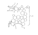
図23に輪転印刷機における各色の印刷ユニット内のインキ装置(インカー)の要部を示す。同図において、1はインキツボ、2はインキツボ1に蓄えられたインキ、3はインキツボローラ、4(4−1〜4−n)はインキツボローラ3の軸方向に複数並設して設けられたインキキー、5はインキ移しローラ、6はインキローラ群、7は版胴8に装着された刷版であり、刷版7には絵柄が焼き付けられている。
FIG. 23 shows the main part of the inking device (inker) in the printing unit for each color in the rotary printing press. In the figure, 1 is an ink fountain, 2 is ink stored in the ink fountain 1, 3 is an ink fountain roller, 4 (4-1 to 4-n) are provided in parallel in the axial direction of the ink fountain roller 3. Ink keys, 5 is an ink transfer roller, 6 is an ink roller group, 7 is a printing plate mounted on the plate cylinder 8, and a pattern is printed on the
このインキ装置では、インキキー4−1〜4−nとインキツボローラ3との間よりインキツボ1内のインキ2をインキツボローラ3に供給し、このインキツボローラ3に供給されたインキをインキ移しローラ5の呼び出し動作によりインキローラ群6を介して刷版7へ供給する。この刷版7に供給されたインキが図示されていないゴム胴を介して印刷用紙に印刷される。
In this ink device, the
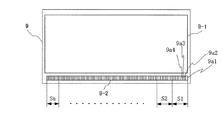
図24にこの印刷機によって印刷された印刷物を示す。印刷物9には、絵柄領域9−1を除く余白部に、帯状のカラーバー9−2が印刷される。カラーバー9−2は、一般の4色刷りの場合、墨(スミ)、シアン(アイ)、マゼンタ(アカ)、イエロー(キ)の濃度測定用のパッチ(網点面積率100%のベタパッチ)9a1,9a2,9a3,9a4を含む領域S1〜Snから構成される。領域S1〜Snは、印刷機における各色の印刷ユニットにおけるインキキー4−1〜4−nのキーゾーンに対応している。
FIG. 24 shows a printed matter printed by this printing machine. On the printed
〔色合わせ〕
各色の印刷ユニットに対しては基準の濃度値が予め設定されている。すなわち、スミ,アイ,アカ,キの各色に対して基準の濃度値が予め設定されており、印刷物9の印刷に際しては、各色の濃度値をこの基準濃度値に一致させるような色合わせ作業が行われる。この色合わせ作業は、印刷物9に印刷されたカラーバー9−2における各色の濃度測定用のパッチ9a(9a1,9a2,9a3,9a4)の濃度に基づき、本刷り開始前(印刷準備段階)や本刷り中にインキ供給量調整装置によって行われる。
[Color matching]
A reference density value is set in advance for each color printing unit. That is, reference density values are set in advance for each of the colors Sumi, Eye, Red, and Ki, and when the printed
例えば、印刷物9における領域S1を代表して説明すると、本刷り開始前や本刷り中に抜き取った印刷物9の各色の濃度測定用のパッチ9aの濃度値を測定し、この測定した各色の濃度値と予め設定されている各色の基準濃度値との濃度差を求め、この求めた各色の濃度差より各色の印刷ユニットにおけるインキキー4−1の開き量の修正量(領域S1へのインキ供給量の修正量)を求め、この求めた修正量をフィードバック量として各色の印刷ユニットにおけるインキキー4−1の開き量を調整する。
For example, the region S1 in the printed
同様にして、領域S2〜Snについても、各色の印刷ユニットにおけるインキキー4−2〜4−nの開き量の修正量(領域S2〜Snへのインキ供給量の修正量)を求め、この求めた修正量をフィードバック量として各色の印刷ユニットにおけるインキキー4−2〜4−nの開き量を調整する(特許文献1参照)。 Similarly, with respect to the areas S2 to Sn, the correction amount of the opening amount of the ink keys 4-2 to 4-n in each color printing unit (the correction amount of the ink supply amount to the areas S2 to Sn) is obtained and obtained. The opening amount of the ink keys 4-2 to 4-n in each color printing unit is adjusted using the correction amount as a feedback amount (see Patent Document 1).
上述した従来のインキ供給量調整方法では、インカー内のインキ搬送経路(インキツボローラからゴム胴までの搬送経路)が長いため、印刷物へのインキ供給量を調整する場合、インキ供給量の調整結果が実際の印刷物に反映され、印刷物に供給されるインキが安定するまでに、インキ供給量が調整されてから150〜250枚の印刷物の印刷を必要とする。 In the conventional ink supply amount adjustment method described above, since the ink conveyance path in the inker (conveyance path from the ink fountain roller to the rubber cylinder) is long, when adjusting the ink supply amount to the printed matter, the adjustment result of the ink supply amount Is reflected in the actual printed matter, and it is necessary to print 150 to 250 printed matter after the ink supply amount is adjusted until the ink supplied to the printed matter is stabilized.
このため、従来は、インキ供給量の調整後、150〜250枚の印刷物の印刷を行った後、印刷された印刷物を検査し、インキ供給量の調整を必要とする場合には、インキ供給量を再調整して、再び150〜250枚の印刷物の印刷を行うという作業を、正常な印刷物が得られるまで何度も繰り返しており、インキ供給量の調整が完了するまでに多くの時間がかかると共に、大量の損紙が発生するという問題が生じていた。 For this reason, conventionally, after adjusting the ink supply amount, after printing 150 to 250 printed materials, the printed product is inspected, and if it is necessary to adjust the ink supply amount, the ink supply amount The process of re-adjusting and printing 150 to 250 printed materials again is repeated many times until a normal printed material is obtained, and it takes a long time to complete the adjustment of the ink supply amount. At the same time, there was a problem that a large amount of waste paper was generated.
また、インキ供給量の調整後、供給されるインキ供給量が安定する前に印刷された印刷物を検査し、再度インキ供給量の調整を行うと、適正な調整を行うことが難しく、供給されるインキ供給量が安定した時の印刷物の濃度が濃くなりすぎたり、薄くなりすぎたりして、ハンチング現象が発生し、余計に時間がかかると共に、より多くの損紙が発生してしまう場合が多々あるという問題があった。 In addition, after adjusting the ink supply amount, the printed matter is inspected before the supplied ink supply amount is stabilized, and the ink supply amount is adjusted again. When the ink supply is stable, the density of the printed matter becomes too thick or too thin, causing hunting phenomenon, which takes more time and often causes more paper loss. There was a problem that there was.
本発明は、このような課題を解決するためになされたもので、その目的とするところは、インキ供給量の調整を短時間で完了し、損紙の発生を少なくすることができる印刷機のインキ供給量調整方法および装置を提供することにある。 The present invention has been made to solve such problems, and the object of the present invention is to provide a printing machine that can complete the adjustment of the ink supply amount in a short time and reduce the occurrence of waste paper. An object of the present invention is to provide an ink supply amount adjusting method and apparatus.
このような目的を達成するために本発明は、印刷物の濃度値を測定し、この測定した濃度値と予め設定されている基準濃度値との濃度差を求め、この求めた濃度差に基づいて刷版へのインキ供給量を調整する印刷機のインキ供給量調整方法において、印刷物の印刷枚数をカウントする工程と、刷版へのインキ供給量調整後の所望の時点で印刷物の濃度値を測定する工程と、所望の時点で測定された印刷物の濃度値とその時の印刷枚数のカウント値とに基づいて刷版へのインキ供給量の修正値を求め、この求めた修正値に基づいて刷版へのインキ供給量を再調整する工程とを設けたものである。なお、本発明は、この方法を適用した装置として構成することもできる。 In order to achieve such an object, the present invention measures the density value of a printed matter, obtains a density difference between the measured density value and a preset reference density value, and based on the obtained density difference. In the method of adjusting the ink supply amount of a printing press that adjusts the ink supply amount to the printing plate, the process of counting the number of printed sheets and the density value of the printed matter are measured at a desired time after adjusting the ink supply amount to the printing plate A correction value for the amount of ink supplied to the printing plate is obtained based on the process to be performed, the density value of the printed matter measured at a desired time and the count value of the number of printed sheets at that time, and the printing plate is obtained based on the obtained correction value. And a step of re-adjusting the ink supply amount. In addition, this invention can also be comprised as an apparatus to which this method is applied.
この発明によれば、インキ供給量の調整後、供給されるインキ供給量が安定する前に印刷物の濃度値を測定すると、この測定した印刷物の濃度値とその時の印刷枚数のカウント値とに基づいてインキ供給量の修正値が求められ、この修正値に基づいてインキ供給量が再調整される。 According to the present invention, when the density value of the printed matter is measured after the ink supply amount is adjusted and before the supplied ink supply amount is stabilized, the density value of the printed matter and the count value of the number of printed sheets at that time are measured. Thus, a correction value of the ink supply amount is obtained, and the ink supply amount is readjusted based on the correction value.
例えば、今、印刷物の濃度値を測定し(1回目の測定)、この測定した濃度値と予め設定されている基準濃度値との濃度差を求め、この求めた濃度差に基づいてインキ供給量を調整したとする(1回目の調整)。この1回目のインキ供給量の調整後、供給されるインキ供給量が安定する前に印刷物の濃度値を測定すると(2回目の測定)、この測定した印刷物の濃度値とその時の印刷枚数のカウント値(前回インキ供給量を調整してから今回印刷物の濃度値を測定するまでの印刷枚数)とに基づいてインキ供給量の修正値が求められ、この修正値に基づいてインキ供給量が再調整される(2回目の調整)。 For example, the density value of the printed material is now measured (first measurement), the density difference between the measured density value and a preset reference density value is obtained, and the ink supply amount is calculated based on the obtained density difference. Is adjusted (first adjustment). After adjusting the ink supply amount for the first time, if the density value of the printed matter is measured before the supplied ink supply amount is stabilized (second measurement), the measured density value of the printed matter and the number of printed sheets at that time are counted. The ink supply amount correction value is calculated based on the value (the number of printed sheets from the previous ink supply amount adjustment to the current print density value measurement), and the ink supply amount is readjusted based on this correction value. (Second adjustment).
同様にして、2回目のインキ供給量の調整後、供給されるインキ供給量が安定する前に印刷物の濃度値を測定すると(3回目の測定)、この測定した印刷物の濃度値とその時の印刷枚数のカウント値(前回インキ供給量を調整してから今回印刷物の濃度値を測定するまでの印刷枚数)とに基づいてインキ供給量の修正値が求められ、この修正値に基づいてインキ供給量が再調整される(3回目の調整)。 Similarly, after adjusting the ink supply amount for the second time and measuring the density value of the printed matter before the supplied ink supply amount is stabilized (the third measurement), the measured density value of the printed matter and the printing at that time are measured. The correction value of the ink supply amount is obtained based on the count value of the number of sheets (the number of printed sheets from the previous adjustment of the ink supply amount to the measurement of the density value of the current printed matter), and the ink supply amount based on the correction value Is readjusted (the third adjustment).
このようにして、本発明では、インキ供給量の調整後、印刷物の濃度値を測定する毎に、測定した印刷物の濃度値とその時の印刷枚数のカウント値とに基づいてインキ供給量の修正値が求められ、この修正値に基づいてインキ供給量が再調整される。 Thus, in the present invention, after adjusting the ink supply amount, every time the density value of the printed matter is measured, the correction value of the ink supply amount is determined based on the measured density value of the printed matter and the count value of the number of printed sheets at that time. And the ink supply amount is readjusted based on this correction value.
本発明では、インキ供給量を再調整する場合、今回測定された印刷物の濃度値とその時の印刷枚数のカウント値とに基づいてインキ供給量の修正値を求めるが、その一例として、印刷枚数のカウント値に基づいて印刷物の今回測定時にあるべき濃度値を推定し、この推定した印刷物の今回測定時にあるべき濃度値と今回測定された印刷物の濃度値とに基づいてインキ供給量の修正値を求める手法が考えられる。なお、この手法において、推定される印刷物の今回測定時にあるべき濃度値をynとすると、この濃度値ynは下記(1)式で表すことができる。 In the present invention, when the ink supply amount is readjusted, a correction value of the ink supply amount is obtained based on the density value of the printed matter measured this time and the count value of the number of printed sheets at that time. Based on the count value, the density value that should be at the current measurement of the printed material is estimated, and the corrected value of the ink supply amount is calculated based on the estimated density value of the printed material at the current measurement time and the density value of the printed material that has been measured this time. The desired method can be considered. In this method, if the estimated density value of the printed material at this time is yn, this density value yn can be expressed by the following equation (1).

但し、(1)式において、xは印刷枚数、yは濃度値を表し、ytは目標とする濃度値、nは今回の測定回数値、kは1≦k≦nでxnm<(xk+xs)を満足する最小の測定回数値、xnmは今回測定時の印刷枚数、xsはインキ供給量が安定するまでに必要とする印刷枚数、yimはi回目に濃度値を測定した時の濃度値、αはインキキー開量に対する濃度値の変化量係数、Kiはi回目のインキキー開量の修正値、f(x)は印刷枚数に関する濃度値の変化関数(0〜1)、xiはi回目にインキキー開量の調整をした時の印刷枚数、yiは(i−1)回目にインキキー開量を調整した時の推定されるi回目の濃度測定時にあるべき濃度値を示す。 In equation (1), x represents the number of printed sheets, y represents a density value, yt represents a target density value, n represents a current measurement number value, k represents 1 ≦ k ≦ n, and xnm <(xk + xs). Satisfactory minimum number of measurements, xnm is the number of printed sheets at the time of measurement, xs is the number of printed sheets required until the ink supply is stabilized, yim is the density value when the density value is measured for the i-th time, and α is Density value variation coefficient with respect to ink key opening amount, Ki is a correction value for the i-th ink key opening amount, f (x) is a density value change function (0 to 1) relating to the number of printed sheets, and xi is an i-th ink key opening amount. The number of printed sheets, yi, when the adjustment is made, indicates the density value that should be in the i-th density measurement estimated when the ink key opening amount is adjusted for the (i-1) th time.
本発明では、インキ供給量を再調整する場合、今回測定された印刷物の濃度値とその時の印刷枚数のカウント値とに基づいてインキ供給量の修正値を求めるが、その一例として、印刷枚数のカウント値に基づいて印刷物の今回測定時にあるべき残りの濃度変化量を推定し、この推定した印刷物の今回測定時にあるべき残りの濃度変化量と今回測定された印刷物の濃度値とに基づいてインキ供給量の修正値を求める手法が考えられる。なお、この手法において、推定される印刷物の今回測定時にあるべき残りの濃度変化量をyn’とすると、この濃度変化量yn’は下記(2)式で表すことができる。 In the present invention, when the ink supply amount is readjusted, a correction value of the ink supply amount is obtained based on the density value of the printed matter measured this time and the count value of the number of printed sheets at that time. Based on the count value, the remaining density change amount that should be at the current measurement of the printed matter is estimated, and the ink density is determined based on the estimated remaining density change amount at the current measurement of the printed matter and the currently measured density value of the printed matter. A method for obtaining a correction value of the supply amount can be considered. In this method, if the remaining density change amount that should be estimated at this time of the printed material is yn ', this density change amount yn' can be expressed by the following equation (2).
但し、(2)式において、xは印刷枚数、yは濃度値を表し、nは今回の測定回数値、kは1≦k≦nでxnm<(xk+xs)を満足する最小の測定回数値、xnmは今回測定時の印刷枚数、xsはインキ供給量が安定するまでに必要とする印刷枚数、yimはi回目に濃度値を測定した時の濃度値、αはインキキー開量に対する濃度値の変化量係数、Kiはi回目のインキキー開量の修正値、f(x)は印刷枚数に関する濃度値の変化関数(0〜1)、xiはi回目にインキキー開量の調整をした時の印刷枚数、yiは(i−1)回目にインキキー開量を調整した時の推定されるi回目の濃度測定時にあるべき濃度値を示す。 However, in the formula (2), x represents the number of printed sheets, y represents the density value, n represents the current measurement number value, k represents the minimum measurement number value satisfying xnm <(xk + xs) with 1 ≦ k ≦ n, xnm is the number of printed sheets at the time of this measurement, xs is the number of printed sheets required until the ink supply amount is stabilized, yim is the density value when the density value is measured for the i-th time, and α is the change in the density value with respect to the ink key opening amount. A quantity coefficient, Ki is a correction value of the i-th ink key opening amount, f (x) is a density value change function (0 to 1) relating to the number of printed sheets, and xi is the number of printed sheets when the ink key opening amount is adjusted for the i-th time. , Yi indicates a density value that should be present at the i-th density measurement estimated when the ink key opening amount is adjusted for the (i-1) th time.
本発明によれば、インキ供給量の調整後、印刷物の濃度値を測定する毎に、測定した印刷物の濃度値とその時の印刷枚数のカウント値とに基づいてインキ供給量の修正値が求められ、この修正値に基づいてインキ供給量が再調整されるものとなり、今回測定時にあるべき濃度値や今回測定時にあるべき残りの濃度変化量などを考慮した適正なインキ供給量の再調整を行うようにして、インキ供給量の調整を短時間で完了し、損紙の発生を少なくすることができるようになる。 According to the present invention, after adjusting the ink supply amount, every time the density value of the printed matter is measured, a corrected value of the ink supply amount is obtained based on the measured density value of the printed matter and the count value of the number of printed sheets at that time. Based on this correction value, the ink supply amount is readjusted, and the appropriate ink supply amount is readjusted taking into account the density value that should be present and the remaining density change that should be present. In this way, the adjustment of the ink supply amount can be completed in a short time, and the generation of waste paper can be reduced.
以下、本発明を図面に基づいて詳細に説明する。
〔原理〕
〔印刷枚数−インキ濃度特性曲線〕
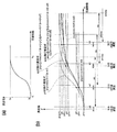
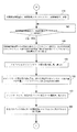
図1(a)にインキキー開量の変化量K(%)に対する印刷枚数とインキ濃度の特性曲線(印刷枚数−インキ濃度特性曲線)を例示する。図1(a)において、横軸は印刷枚数x、縦軸は濃度値yを表し、x1はインキキー開量をK%変化させる直前の印刷枚数、y1は印刷枚数x1におけるインキ濃度であり、印刷枚数x1の時点において濃度値はy1で安定しているものとする。xeはインキキー開量をK%変化させたことによって最終的な濃度値に達したときの印刷枚数、yeはインキキー開量をK%変化させたことによる最終的な濃度値である。
Hereinafter, the present invention will be described in detail based on the drawings.
〔principle〕
[Number of printed sheets-Ink density characteristic curve]
FIG. 1A illustrates a characteristic curve of the number of printed sheets and ink density (number of printed sheets-ink density characteristic curve) with respect to the change amount K (%) of the ink key opening amount. In FIG. 1A, the horizontal axis represents the number of printed sheets x, the vertical axis represents the density value y, x1 represents the number of printed sheets immediately before the ink key opening amount is changed by K%, and y1 represents the ink density at the number of printed sheets x1. It is assumed that the density value is stable at y1 at the time of the number x1. xe is the number of printed sheets when the final density value is reached by changing the ink key opening amount by K%, and ye is the final density value by changing the ink key opening amount by K%.
図1(a)において、インキキー開量に対する濃度値の変化量係数をα、xsをインキ濃度が安定するまでに必要とする印刷枚数(xs=xe−x1)とすると、インキキーをK(%)変化されてからの印刷枚数xと濃度値yとの関係は、すなわち図1(a)に示した印刷枚数−インキ濃度特性曲線は、y=y1+α・K・f(x−x1)で表すことができる。但し、y=f(x)の範囲は0から1で正規化され、最終的なインキ濃度の変化量はα・Kとする。この関数f(x)及びαは実験データにより算出することができるが、印刷機の機種、つまり、インキ装置の構成によってその値が変動する。 In FIG. 1A, assuming that the variation coefficient of the density value with respect to the ink key opening amount is α and xs is the number of printed sheets (xs = xe−x1) required until the ink density is stabilized, the ink key is K (%). The relationship between the number of printed sheets x and the density value y after the change, that is, the number of printed sheets-ink density characteristic curve shown in FIG. 1A is expressed by y = y1 + α · K · f (x−x1). Can do. However, the range of y = f (x) is normalized from 0 to 1, and the final ink density change amount is α · K. The functions f (x) and α can be calculated from experimental data, but their values vary depending on the printer model, that is, the configuration of the inking device.
〔印刷枚数−インキ濃度特性曲線を利用したインキ供給量の調整〕
図1(b)は本発明に係る印刷機のインキ供給量調整方法の1手法を説明する図である。同図において、横軸は印刷枚数x、縦軸は濃度値yを表し、ytは目標とする濃度値(基準濃度値)を示す。この例では、印刷枚数x1mの時点t0で印刷物の濃度値がy1mで安定しているものとする。すなわち、現在、印刷物の印刷が行われており、x1m枚印刷した時点t0で、印刷物の濃度値がy1mで安定しているものとする。
[Adjustment of ink supply using the number of printed sheets-ink density characteristic curve]
FIG. 1B is a view for explaining one method of the ink supply amount adjusting method of the printing press according to the present invention. In the figure, the horizontal axis represents the number of printed sheets x, the vertical axis represents the density value y, and yt represents the target density value (reference density value). In this example, it is assumed that the density value of the printed material is stable at y1m at time t0 when the number of printed sheets x1m. That is, it is assumed that the printed material is currently being printed, and the density value of the printed material is stable at y1m at time t0 when x1m sheets are printed.
〔測定&調整:1回目〕
今、時点t0において、印刷物の濃度値を基準濃度値yt(=y1)に一致させる色合わせ作業を開始するものとする。この場合、x1m枚目の印刷物を抜き取り、この印刷物の濃度値y1mを測定する(1回目の測定)。
[Measurement & Adjustment: First time]
Now, at time t0, a color matching operation for matching the density value of the printed material with the reference density value yt (= y1) is started. In this case, the x1m-th printed matter is extracted, and the density value y1m of this printed matter is measured (first measurement).
そして、下記(3)式より、K1=(yt−y1m)/αとしてインキキー開量の修正値K1を求め、この修正値K1に基づいてインキキーの開き量を調整する(1回目の調整)。
yt=y1m+α・K1 ・・・・(3)
なお、(3)式において、αはインキキー開量に対する濃度値の変化量係数であり、インキキーに対して予め定められる係数である。
Then, from the following equation (3), a correction value K1 for the ink key opening amount is obtained as K1 = (yt−y1m) / α, and the ink key opening amount is adjusted based on the correction value K1 (first adjustment).
yt = y1m + α · K1 (3)
In the equation (3), α is a density value variation coefficient with respect to the ink key opening, and is a coefficient determined in advance for the ink key.
ここで、時点t0を印刷物の濃度値の測定時(1回目測定時)とし、時点t1をインキキーの開き量の修正完了時(1回目修正完了時)とし、1回目修正完了時の印刷物の印刷枚数をx1とすると、x1以降の印刷枚数と濃度値との関係は、すなわちx1以降の印刷物の濃度値の推定式は、下記(4)式で表される。
y=y1m+α・K1・f(x−x1) ・・・・(4)
Here, it is assumed that the time point t0 is when the density value of the printed material is measured (during the first measurement), and the time point t1 is when the ink key opening amount correction is completed (when the first correction is completed), and the printed material is printed when the first correction is completed. When the number of sheets is x1, the relationship between the number of printed sheets after x1 and the density value, that is, the estimation formula for the density value of the printed material after x1, is expressed by the following expression (4).
y = y1m + α · K1 · f (x−x1) (4)
〔測定&調整:2回目〕
次に、印刷枚数がx1+xs(xs:インキ供給量が安定するまでに必要とする印刷枚数)に達するよりも前のt2時点において、すなわちインキ供給量が安定する前のt2時点において、x2m枚目の印刷物を抜き取り(x2m<(x1+xs))、この印刷物の濃度値y2mを測定する(2回目の測定)。
[Measurement & Adjustment: Second time]
Next, at time t2 before the number of printed sheets reaches x1 + xs (xs: number of printed sheets required until the ink supply amount is stabilized), that is, at time t2 before the ink supply amount is stabilized, the x2m-th sheet. The printed material is extracted (x2m <(x1 + xs)), and the density value y2m of the printed material is measured (second measurement).
そして、下記(5)式より、K2=(y2−y2m)/αとしてインキキー開量の修正値K2を求め、この修正値K2に基づいてインキキーの開き量を再調整する(2回目の調整)。
y2=y2m+α・K2 ・・・・(5)
なお、(5)式において、y2は今回測定時(2回目測定時)にあるべき印刷物の濃度値であり、上記(4)式より、y2=y1m+α・K1・f(x2m−x1)として推定される。
Then, from the following equation (5), a correction value K2 of the ink key opening amount is obtained as K2 = (y2−y2m) / α, and the ink key opening amount is readjusted based on the correction value K2 (second adjustment). .
y2 = y2m + α · K2 (5)
In equation (5), y2 is the density value of the printed material that should be present at the time of the current measurement (second measurement), and is estimated as y2 = y1m + α · K1 · f (x2m−x1) from equation (4). Is done.
ここで、時点t2を印刷物の濃度値の測定時(2回目測定時)とし、時点t3をインキキーの開き量の修正完了時(2回目修正完了時)とし、2回目修正完了時の印刷物の印刷枚数をx2とすると、x2以降の印刷枚数と濃度値との関係は、すなわちx2以降の印刷物の濃度値の推定式は、下記(6)式で表される。
y=yt+〔y1m+α・K1・f(x−x1)−y1〕+〔y2m+α・K2・f(x−x2)−y2〕 ・・・・(6)
Here, it is assumed that the time point t2 is when the density value of the printed material is measured (second time measurement), and the time point t3 is when the correction of the ink key opening amount is completed (second time correction is completed), and the printed material is printed when the second correction is completed. When the number of sheets is x2, the relationship between the number of printed sheets after x2 and the density value, that is, the estimation formula for the density value of the printed material after x2, is expressed by the following expression (6).
y = yt + [y1m + α · K1 · f (x−x1) −y1] + [y2m + α · K2 · f (x−x2) −y2] (6)
上記(6)式は、印刷枚数(x2+xs)において目標とする濃度値ytに到達する式であり、下記(7)式より導出されたものである。
y=yt−〔(1回目の修正に対する残りの濃度変化量)+(2回目の修正に対する残りの濃度変化量)〕 ・・・・(7)
The above expression (6) is an expression for reaching the target density value yt in the number of printed sheets (x2 + xs), and is derived from the following expression (7).
y = yt − [(Remaining density change amount for the first correction) + (Remaining density change amount for the second correction)] (7)
(7)式において、1回目の修正に対する残りの濃度変化量は、y1−(y1m+α・K1・f(x−x1))と表され、2回目の修正に対する残りの濃度変化量は、y2−(y2m+α・K2・f(x−x2))と表される。従って、(7)式は、
y=yt−〔{y1−(y1m+α・K1・f(x−x1)}+{y2−(y2m+α・K2・f(x−x2))}) ・・・・(8)
と表され、この式を展開することによって上記(6)式が得られる。
In equation (7), the remaining density change amount for the first correction is expressed as y1− (y1m + α · K1 · f (x−x1)), and the remaining density change amount for the second correction is y2−2. (Y2m + α · K2 · f (x−x2)). Therefore, equation (7) is
y = yt − [{y1− (y1m + α · K1 · f (x−x1)} + {y2− (y2m + α · K2 · f (x−x2))}) (8)
The above equation (6) is obtained by developing this equation.
〔測定&調整:3回目〕
次に、印刷枚数がx2+xsに達するよりも前のt4時点において、x3m枚目の印刷物を抜き取り(x3m<(x2+xs))、この印刷物の濃度値y3mを測定する(3回目の測定)。
[Measurement and adjustment: 3rd time]
Next, at time t4 before the number of printed sheets reaches x2 + xs, the x3m-th printed matter is extracted (x3m <(x2 + xs)), and the density value y3m of the printed matter is measured (third measurement).
そして、下記(9)式より、K3=(y3−y3m)/αとしてインキキー開量の修正値K3を求め、この修正値K3に基づいてインキキーの開き量を再調整する(3回目の調整)。
y3=y3m+α・K3 ・・・・(9)
なお、(9)式において、y3は今回測定時(3回目測定時)にあるべき印刷物の濃度値であり、上記(6)式より、y3=yt+〔y1m+α・K1・f(x3m−x1)−y1〕+〔y2m+α・K2・f(x3m−x2)−y2〕として推定される。
Then, from the following equation (9), a correction value K3 for the ink key opening amount is obtained as K3 = (y3−y3m) / α, and the ink key opening amount is readjusted based on the correction value K3 (third adjustment). .
y3 = y3m + α · K3 (9)
In equation (9), y3 is the density value of the printed material that should be present at the time of this measurement (during the third measurement). From equation (6), y3 = yt + [y1m + α · K1 · f (x3m−x1) −y1] + [y2m + α · K2 · f (x3m−x2) −y2].
ここで、時点t4を印刷物の濃度値の測定時(3回目測定時)とし、時点t5をインキキーの開き量の修正完了時(3回目修正完了時)とし、3回目修正完了時の印刷物の印刷枚数をx3とすると、x3以降の印刷枚数と濃度値との関係は、すなわちx3以降の印刷物の濃度値の推定式は、下記(10)式で表される。
y=yt+〔y1m+α・K1・f(x−x1)−y1〕+〔y2m+α・K2・f(x−x2)−y2〕+〔y3m+α・K3・f(x−x3)−y3〕 ・・・・(10)
Here, when the density value of the printed material is measured (when the third measurement is performed), the time point t4 is when the correction of the ink key opening amount is completed (when the third correction is completed), and the printed material is printed when the third correction is completed. When the number of sheets is x3, the relationship between the number of printed sheets after x3 and the density value, that is, the estimation formula for the density value of the printed material after x3 is expressed by the following expression (10).
y = yt + [y1m + α · K1 · f (x−x1) −y1] + [y2m + α · K2 · f (x−x2) −y2] + [y3m + α · K3 · f (xx3) −y3]・ (10)
〔測定&調整:4回目〕
次に、印刷枚数がx3+xsに達するよりも前のt6時点において、x4m枚目の印刷物を抜き取り(x4m<(x3+xs))、この印刷物の濃度値y4mを測定する(4回目の測定)。
[Measurement & Adjustment: 4th time]
Next, at time t6 before the number of printed sheets reaches x3 + xs, the x4m-th printed matter is extracted (x4m <(x3 + xs)), and the density value y4m of the printed matter is measured (fourth measurement).
そして、下記(11)式より、K4=(y4−y4m)/αとしてインキキー開量の修正値K4を求め、この修正値K4に基づいてインキキーの開き量を再調整する(4回目の調整)。
y4=y4m+α・K4 ・・・・(11)
Then, from the following equation (11), a correction value K4 for the ink key opening amount is obtained as K4 = (y4−y4m) / α, and the ink key opening amount is readjusted based on the correction value K4 (fourth adjustment). .
y4 = y4m + α · K4 (11)
なお、(11)式において、y4は今回測定時(4回目測定時)にあるべき印刷物の濃度値であり、上記(10)式より、y4=yt+〔y1m+α・K1・f(x3m−x1)−y1〕+〔y2m+α・K2・f(x3m−x2)−y2〕+〔y3m+α・K3・f(x−x3)−y3〕として推定される。但し、図1(b)の例では、今回測定時の印刷枚数x4mがx4m>(x1+xs)であり、1回目の修正に対する今回測定時の残りの濃度変化量が零であるので、〔y1m+α・K1・f(x3m−x1)−y1〕の項は除外する。 In equation (11), y4 is the density value of the printed material that should be present at the time of the current measurement (during the fourth measurement). From equation (10), y4 = yt + [y1m + α · K1 · f (x3m−x1) −y1] + [y2m + α · K2 · f (x3m−x2) −y2] + [y3m + α · K3 · f (x−x3) −y3]. However, in the example of FIG. 1B, the number of printed sheets x4m at the time of the current measurement is x4m> (x1 + xs), and the remaining density change amount at the time of the current measurement with respect to the first correction is zero, so [y1m + α · The term “K1 · f (x3m−x1) −y1]” is excluded.
以下同様にして、印刷物の濃度値を測定する毎に、測定された印刷物の濃度値と,そのときの印刷枚数(前回インキ供給量を調整してから今回印刷物の濃度値を測定するまでの印刷枚数)に基づいて推定される印刷物の今回測定時にあるべき濃度値とに基づいてインキキー開量の修正値を求め、この求めた修正値に基づいてインキキーの開き量を調整して行く。これにより、印刷物の濃度値を測定する毎に、今回測定時にあるべき濃度値を考慮した適正なインキ供給量の再調整が行われるものとなり、インキ供給量の調整が短時間で完了し、損紙の発生が少なくなる。 In the same manner, each time the density value of the printed matter is measured, the measured density value of the printed matter and the number of printed sheets at that time (printing from the previous ink supply amount adjustment until the current density value of the printed matter is measured) A correction value of the ink key opening amount is obtained based on the density value that should be obtained at the time of the current measurement of the printed matter estimated on the basis of the number of prints), and the ink key opening amount is adjusted based on the obtained correction value. As a result, each time the density value of the printed material is measured, the appropriate ink supply amount is adjusted again taking into account the density value that should be present at the time of the current measurement. Less paper is generated.
この手法において、今回測定時にあるべき濃度値をynとすると、この濃度値ynは下記(12)式で表される。 In this method, if the density value that should be present at the time of measurement is yn, the density value yn is expressed by the following equation (12).
但し、(12)式において、ytは目標とする濃度値、nは今回の測定回数値、kは1≦k≦nでxnm<(xk+xs)を満足する最小の測定回数値、xnmは今回測定時の印刷枚数、xsはインキ供給量が安定するまでに必要とする印刷枚数、yimはi回目に濃度値を測定した時の濃度値、αはインキキー開量に対する濃度値の変化量係数、Kiはi回目のインキキー開量の修正値、f(x)は印刷枚数に関する濃度値の変化関数(0〜1)、xiはi回目にインキキー開量の調整をした時の印刷枚数、yiは(i−1)回目にインキキー開量を調整した時の推定されるi回目の濃度測定時にあるべき濃度値を示す。 In equation (12), yt is the target concentration value, n is the current measurement value, k is the minimum measurement value that satisfies 1 ≦ k ≦ n and xnm <(xk + xs), and xnm is the current measurement value. Xs is the number of printed sheets required until the ink supply is stabilized, yim is the density value when the density value is measured for the i-th time, α is the coefficient of change in density value relative to the ink key opening amount, Ki Is the correction value for the i-th ink key opening amount, f (x) is a density value change function (0 to 1) relating to the number of printed sheets, xi is the number of printed sheets when the ink key opening amount is adjusted for the i-th time, and yi is ( i-1) Indicates a density value that should be present at the i-th density measurement estimated when the ink key opening amount is adjusted for the first time.
なお、上述した手法では、印刷物の今回測定時にあるべき濃度値を推定し、この推定した印刷物の今回測定時にあるべき濃度値と今回測定された印刷物の濃度値とに基づいてインキキー開量の修正値を求めるようにしたが、印刷物の今回測定時にあるべき残りの濃度変化量を推定し、この推定した印刷物の今回測定時にあるべき残りの濃度変化量と今回測定された印刷物の濃度値に基づいてインキキー開量の修正値を求めるようにしてもよい。この場合、推定される今回測定時にあるべき残りの濃度変化量をyn’とすると、この濃度変化量yn’は下記(13)式で表すことができる。 In the above-described method, the density value that should be at the current measurement of the printed material is estimated, and the ink key opening amount is corrected based on the estimated density value at the current measurement of the printed material and the density value of the printed material that has been measured this time. The remaining density change amount that should be present at the time of the current measurement of the printed matter is estimated, and the estimated remaining amount change amount of the printed matter at the current measurement time and the density value of the printed matter that has been measured this time are estimated. Thus, the correction value of the ink key opening amount may be obtained. In this case, if the remaining density change amount that should be estimated at the current measurement is yn ', this density change amount yn' can be expressed by the following equation (13).
但し、(13)式において、nは今回の測定回数値、kは1≦k≦nでxnm<(xk+xs)を満足する最小の測定回数値、xnmは今回測定時の印刷枚数、xsはインキ供給量が安定するまでに必要とする印刷枚数、yimはi回目に濃度値を測定した時の濃度値、αはインキキー開量に対する濃度値の変化量係数、Kiはi回目のインキキー開量の修正値、f(x)は印刷枚数に関する濃度値の変化関数(0〜1)、xiはi回目にインキキー開量の調整をした時の印刷枚数、yiは(i−1)回目にインキキー開量を調整した時の推定されるi回目の濃度測定時にあるべき濃度値を示す。 However, in the equation (13), n is the current measurement number value, k is the minimum measurement number value satisfying xnm <(xk + xs) with 1 ≦ k ≦ n, xnm is the number of printed sheets at the current measurement, and xs is the ink. The number of printed sheets required until the supply amount is stabilized, yim is the density value when the density value is measured at the i-th time, α is the coefficient of change in density value relative to the ink key opening amount, and Ki is the ink key opening amount at the i-th time. The correction value, f (x) is a density value change function (0 to 1) regarding the number of printed sheets, xi is the number of printed sheets when the ink key opening amount is adjusted for the i-th time, and yi is the ink key opened for the (i-1) -th time. The density value which should be at the time of the i-th density | concentration measurement estimated when the quantity is adjusted is shown.
〔実施の形態1:今回測定時にあるべき濃度値に基づく例(方式1)〕
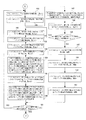
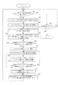
図2はこの発明の一実施の形態を示す濃度測定及びインキ供給量調整装置(以下、単にインキ供給量調整装置と呼ぶ)のブロック図である。このインキ供給量調整装置10は、CPU10A、RAM10B、ROM10C、入力装置10D、表示器10E、出力装置10F、入出力インターフェイス(I/O,I/F)10G〜10K、測色計10L、測色計移動用モータ10M、ロータリーエンコーダ10N、モータドライバ10P、カウンタ10Q、A/D変換器10R、D/A変換器10S、測色計原点位置検出器10TおよびメモリM1〜M22を備えている。
[Embodiment 1: Example based on concentration value to be present at the time of measurement (method 1)]
FIG. 2 is a block diagram of a density measurement and ink supply amount adjusting device (hereinafter simply referred to as an ink supply amount adjusting device) showing an embodiment of the present invention. The ink supply
CPU10Aは、インターフェイス10G〜10Kを介して与えられる各種入力情報を得て、RAM10BやメモリM1〜M22にアクセスしながら、ROM10Cに格納されたプログラムに従って動作する。入力装置10Dには、測定スタートスイッチSW1や制御終了スイッチSW2などが設けられている。ロータリーエンコーダ10Nは、測色計移動用モータ10Mの所定回転数(角度)毎に回転パルスを発生してカウンタ10Qに出力する。
The
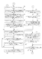
なお、図2において、11(11−1〜11−n)は、図23に示した各色のインキキー4(4−1〜4−n)に対応して各個に設けられたインキキー制御装置である。これらインキキー制御装置11−1〜11−nによって、インキキー4−1〜4−nのインキツボローラ3に対する開き量が各個に調整される。インキキー制御装置11は、図3に示すように、インキキー駆動用モータドライバ11Aと、インキキー駆動用モータ11Bと、ロータリーエンコーダ11Cと、カウンタ11Dと、CPU11Eと、ROM11Fと、RAM11Gと、メモリ11H〜11Kと、インターフェース(I/O,I/F)11L,11Mとを備えており、インターフェイス11Lを介してインキ供給量調整装置10と接続されている。ロータリーエンコーダ11Cは、インキキー駆動用モータ11Bの所定回転数(角度)毎に回転パルスを発生してカウンタ11Dに出力する。
In FIG. 2, 11 (11-1 to 11-n) is an ink key control device provided for each of the ink keys 4 (4-1 to 4-n) of each color shown in FIG. . By these ink key control devices 11-1 to 11-n, the opening amounts of the ink keys 4-1 to 4-n with respect to the ink fountain roller 3 are adjusted to individual pieces. As shown in FIG. 3, the ink
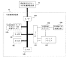
また、図2において、12は印刷機制御装置である。印刷機制御装置12は、図4に示すように、印刷機の1回転毎にパルス信号を生成する印刷機1回転検出器12Aと、印刷機1回転検出器12Aからのパルス信号を受けて印刷物の印刷枚数をカウントする印刷枚数カウンタ12Bと、フリップフロップ12Cと、CPU12Dと、ROM12Eと、RAM12Fと、印刷枚数カウンタ12Bのカウント値を記憶するメモリ12Gと、インターフェース(I/O,I/F)12H,12Iとを備えており、インターフェイス12Hを介してインキ供給量調整装置10と接続されている。フリップフロップ12Cは、CPU12Dからの指令を受けて、印刷枚数カウンタ12Bに印刷開始(カウント開始)および印刷停止(カウント終了)のタイミングを知らせる。
In FIG. 2,
図2において、メモリM1には、過去の修正完了時の印刷枚数が記憶される。メモリM2には、過去の修正時の各インキキーの開き量の修正量が記憶される。メモリM3には、過去の修正時の各色の各パッチの測定濃度値が記憶される。メモリM4には、過去の修正時の各色の各パッチの修正目標濃度値が記憶される。メモリM5には、過去の修正に対する今回測定時にあるべき各色の各パッチの残りの濃度変化量の合計値が記憶される。 In FIG. 2, the memory M1 stores the number of printed sheets at the time of past correction completion. The memory M2 stores a correction amount of the opening amount of each ink key at the time of past correction. In the memory M3, the measured density value of each patch of each color at the time of past correction is stored. The memory M4 stores the correction target density value of each patch of each color at the time of past correction. The memory M5 stores the total density change amount remaining for each patch of each color that should be present during the current measurement with respect to past corrections.
メモリM6には、カラーバーの各色の基準濃度値が記憶される。メモリM7には、カラーバーの各色の許容濃度差が記憶される。メモリM8には、測色計によって測定すべきカラーバーの各色の各パッチの位置が記憶される。メモリM9には、今回測定時の印刷枚数が記憶される。メモリM10には、測色計の現在位置測定用のカウンタの値が記憶される。メモリM11には、測色計の現在位置が記憶される。 The memory M6 stores a reference density value for each color of the color bar. The memory M7 stores an allowable density difference for each color of the color bar. The memory M8 stores the position of each patch of each color of the color bar to be measured by the colorimeter. The memory M9 stores the number of printed sheets at the current measurement. The memory M10 stores the value of the counter for measuring the current position of the colorimeter. The memory M11 stores the current position of the colorimeter.
メモリM12には、カラーバーの各色の各パッチの色データが記憶される。メモリM13には、各色の各パッチの今回測定時の濃度値が記憶される。メモリM14には、過去の修正完了時から今回測定時までの印刷枚数が記憶される。メモリM15には、修正後、印刷濃度が安定するまでの印刷枚数(インキ供給量が安定するまでに必要とする印刷枚数)が記憶される。メモリM16には、各色の印刷枚数−インキ濃度特性曲線が記憶される。 The memory M12 stores color data of each patch of each color of the color bar. The memory M13 stores the density value at the time of the current measurement of each patch of each color. The memory M14 stores the number of printed sheets from the completion of past corrections to the current measurement. The memory M15 stores the number of printed sheets until the printing density is stabilized after correction (the number of printed sheets required until the ink supply amount is stabilized). The memory M16 stores the number of printed sheets of each color-ink density characteristic curve.
メモリM17には、過去の修正に対する今回測定時にあるべき各色の各パッチの残りの濃度変化量が記憶される。メモリM18には、今回測定時にあるべき各色の各パッチの濃度値が記憶される。メモリM19には、各色の各パッチの修正すべき濃度差が記憶される。メモリM20には、各色の各パッチの修正すべき濃度差の絶対値が記憶される。メモリM21には、各色の各パッチの濃度差−インキキー開き量の修正量変換テーブルが記憶される。メモリM22には、各インキキーの開き量の修正量が記憶される。 The memory M17 stores the remaining density change amount of each patch of each color that should be present during the current measurement with respect to past corrections. The memory M18 stores the density value of each color patch that should be present at the time of measurement. The memory M19 stores a density difference to be corrected for each patch of each color. The memory M20 stores the absolute value of the density difference to be corrected for each patch of each color. The memory M21 stores a correction amount conversion table of density difference-ink key opening amount of each patch of each color. The memory M22 stores a correction amount for each ink key opening amount.
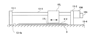
測色計10Lは、図5に示すように、支柱13−1,13−2間に設けられたボールネジ(送りねじ)13−3に取り付けられている。ボールネジ13−3は測色計移動用モータ10Mによって正/逆回転する。このボールネジ13−3の正/逆回転により、ボールネジ13−3に案内されながら、測色計10Lが支柱13−1,13−2間を移動する。測色計10Lのヘッド部10L1 は測定台13−4の測定対象が置かれる面13−4aに向けられている。
As shown in FIG. 5, the
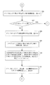
〔色合わせ〕
現在、印刷物の印刷が行われており、印刷物の各色の濃度値が安定しているものとする。この濃度値が安定している状態から、印刷物の各色の濃度値を基準濃度値に一致させるべく、色合わせ作業を開始するものとする。なお、この色合わせ作業中、印刷物の印刷は中断することなく、続けられるものとする。
[Color matching]
It is assumed that the printed material is currently printed and the density value of each color of the printed material is stable. From this state where the density value is stable, the color matching operation is started in order to make the density value of each color of the printed matter coincide with the reference density value. It should be noted that during this color matching operation, printing of the printed material can be continued without interruption.
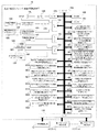
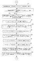
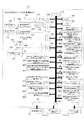
この色合わせ作業に先立って、インキ供給量調整装置10のCPU10Aは、メモリM1,M2,M3,M4を初期化し(図6に示すステップ101,102,103,104)、オペレータより入力されるカラーバーの各色の基準濃度値および許容濃度差をメモリM6およびM7に格納する(ステップ105)。また、オペレータより入力されるカラーバーの各色の各パッチの位置を取り込み(ステップ106)、この各色の各パッチの位置に基づき、測色計によって測定すべきカラーバーの各色の各パッチの位置(測定位置)を演算し、演算した測定位置をメモりM8に格納する(ステップ107)。
Prior to this color matching operation, the
〔測定&調整:1回目〕
オペレータは、入力装置10Dの測定スタートスイッチSW1をオンとし、色合わせ作業を開始する。CPU10Aは、この測定スタートスイッチSW1のオンを確認し(ステップ109のYES)、メモリM5の記憶内容を「0」としたうえ(ステップ110)、印刷機制御装置12(図4)に印刷枚数の送信指令を送る(図7に示すステップ111)。
[Measurement & Adjustment: First time]
The operator turns on the measurement start switch SW1 of the
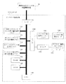
図13に印刷機制御装置12のCPU12Dが行う処理フローを示す。印刷機制御装置12のCPU12Dは、印刷開始が指示されると(ステップ204のYES)、フリップフロップ12Cにセット信号を送り(ステップ205)、印刷枚数カウンタ12Bにおけるカウント動作を開始させる。印刷停止が指示されると(ステップ206のYES)、フリップフロップ12Cにリセット信号を送り(ステップ207)、印刷枚数カウンタ12Bにおけるカウント動作を停止させる。インキ供給量調整装置10より印刷枚数の送信指令が送られてくると(ステップ201のYES)、その時の印刷枚数カウンタ12Bのカウント値を読み取り(ステップ202)、この読み取った印刷枚数カウンタ12Bのカウント値、すなわち現在の印刷物の印刷枚数をインキ供給量調整装置10へ送信する(ステップ203)。
FIG. 13 shows a processing flow performed by the
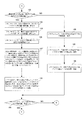
インキ供給量調整装置10のCPU10Aは、印刷機制御装置12からの印刷物の印刷枚数を受信し(ステップ112のYES)、この受信した印刷枚数を今回測定時(1回目)の印刷枚数x1mとしてメモリM9に格納する(ステップ113)。
The
一方、オペレータは、印刷機によって印刷されたx1m枚目の印刷物を測定対象とし、測定台13−4(図5)にセットする。このセット状態において、印刷物9に印刷されたカラーバー9−2は、測色計10Lのヘッド部10L1 の下面に位置する。
On the other hand, the operator sets the x1m-th printed matter printed by the printing machine as a measurement target and sets it on the measurement table 13-4 (FIG. 5). In this set state, the color bar 9-2 printed on the printed
このx1m枚目の印刷物9のセット状態において、CPU10Aは、モータドライバ10Pに正転指令を送り、測色計移動用モータ10Mを正転させる(ステップ114)。測色計移動用モータ10Mの正転によりボールネジ13−3が正転し、このボールネジ13−3に案内されて測色計10Lが支柱13−1に接する原点位置から支柱13−2方向へ向けて移動する。
In the set state of the x1m-th printed
CPU10Aは、測色計現在位置測定用カウンタ10Qのカウント値を読み込むと共に、その読み込んだカウント値をメモリM10に格納する(ステップ115)。また、読み込んだ測色計現在位置測定用カウンタ10Qのカウント値より、測色計10Lの現在位置を演算し、メモリM11に格納する(ステップ116)。そして、測色計10LがメモリM8に記憶されている最初の測定位置に達したときに(ステップ117のYES)、その測定位置に位置するパッチ9aの色データを測色計10Lにより採取し、採取した色データをメモリM12に格納する(ステップ118,119)。
The
以下同様にして、CPU10Aは、メモリM8に記憶されている測定位置に達するごとに、その測定位置に位置するパッチ9aの色データを測色計10Lにより採取し、採取した色データをメモリM12に格納して行く。すなわち、CPU10Aは、測色計10Lを自動走査制御することによって、x1m枚目の印刷物に印刷されたカラーバーの各色の各パッチの色データを次々に採取して行く。
Similarly, every time the
CPU10Aは、x1m枚目の印刷物に印刷されたカラーバーの全てのパッチの色データ採取が完了したか否かを判断し(ステップ120)、採取完了により、測色計移動用モータ10Mの正転を停止させる(ステップ121)。次に、測色計移動用モータ10Mを逆転させ(ステップ122)、測色計10Lを原点位置へ復帰させた後(ステップ123のYES)、測色計移動用モータ10Lの逆転を停止させる(ステップ124)。
The
そして、メモリM12に格納された各色の各パッチの色データより各色の各パッチの濃度値を算出し、今回測定時(1回目)の濃度値としてメモリM13に格納する(ステップ125)。本実施の形態では、測色計10Lとして分光計を使用しており、濃度計で各色のベタパッチを測定する時に用いるフィルタの各波長の透過率を分光計からの各波長の出力値に掛け、それらを合計することによって各色の濃度値を求めるようにしている。
Then, the density value of each patch of each color is calculated from the color data of each patch of each color stored in the memory M12, and stored in the memory M13 as the density value at the time of the current measurement (first time) (step 125). In the present embodiment, a spectrometer is used as the
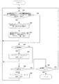
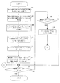
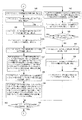
次に、CPU10Aは、メモリM1より過去の修正完了時の印刷枚数を読み込む(図8に示すステップ126)。この場合、メモリM1は先のステップ101で初期化されており、メモリM1内にデータはない。このため、CPU10Aは、ステップ127のYESに応じて、図11のステップ167へ進み、メモリM6より各色の基準濃度値を読み出す。
Next, the
そして、メモリM13より各色の各パッチの今回測定時の濃度値を読み出し(ステップ168)、各色の基準濃度値より各色の各パッチの今回測定時の濃度値を減算し、各色の各パッチの修正すべき濃度差を求め、これをメモリM19へ格納する(ステップ169)。また、各色の各パッチの修正すべき濃度差の絶対値を求め、これをメモリM20へ格納する(ステップ170)。 Then, the current density value of each patch of each color is read from the memory M13 (step 168), and the current density value of each patch of each color is subtracted from the reference density value of each color to correct each patch of each color. The density difference to be obtained is obtained and stored in the memory M19 (step 169). Further, the absolute value of the density difference to be corrected for each patch of each color is obtained and stored in the memory M20 (step 170).
次に、CPU10Aは、メモリM7より各色の許容濃度差を読み出す(ステップ171)。そして、各色の各パッチの修正すべき濃度差の絶対値と各色の許容濃度差とを比較し(ステップ172)、修正すべき濃度差が許容濃度差よりも小さいパッチについては(ステップ172のYES)、メモリM19内の対応する各色の各パッチの修正すべき濃度差を零としたうえ(ステップ173)、ステップ174へ進む。
Next, the
ステップ174において、CPU10Aは、メモリM21より各色のパッチの濃度差−インキキー開き量の修正量変換テーブルを読み出す。そして、この読み出した各色のパッチの濃度差−インキキー開き量の修正量変換テーブルを用いて、メモリM19に格納されている各色の各パッチの修正すべき濃度差より、対応する各インキキーの開き量の修正量を求め、メモリM22に格納する(ステップ175)。また、この求めた各インキキーの開き量の修正量を、各インキキー制御装置11(図3)に送信する(ステップ176)。
In
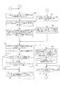
各インキキー制御装置11では、インキ供給量調整装置10からのインキキーの開き量の修正量を受けると(図14に示すステップ301のYES)、この受け取った修正量をメモリ11Kに格納するとともに(ステップ302)、カウンタ11Dのカウント値を読み取り(ステップ303)、この読み取ったカウンタ11Dのカウント値より現在のインキキーの開き量を求める(ステップ304)。そして、インキキーの開き量の修正量および現在のインキキーの開き量より、目標とするインキキーの開き量を求める(ステップ305)。
When each ink
目標とするインキキーの開き量が現在のインキキーの開き量と同じであれば(ステップ306のYES)、直ちにステップ312へ進み、インキ供給量調整装置10へインキキーの開き量の修正完了信号を出力する。
If the target ink key opening amount is the same as the current ink key opening amount (YES in step 306), the process immediately proceeds to step 312 to output an ink key opening amount correction completion signal to the ink supply
目標とするインキキーの開き量が現在のインキキーの開き量と同じでない場合には(ステップ306のNO)、目標とするインキキーの開き量と現在のインキキーの開き量とが同じになるまでインキキー駆動用モータ11Bを駆動した後(ステップ307〜311)、インキ供給量調整装置10へインキキーの開き量の修正完了信号を出力する(ステップ312)。
If the target ink key opening amount is not the same as the current ink key opening amount (NO in step 306), the ink key driving is performed until the target ink key opening amount and the current ink key opening amount are the same. After driving the
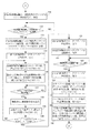
インキ供給量調整装置10のCPU10Aは、全てのインキキー制御装置11からのインキキーの開き量の修正完了信号を受けると(図11に示すステップ177のYES)、印刷機制御装置12に印刷枚数の送信指令を送る(図12に示すステップ178)。この送信指令に応えて、印刷機制御装置12よりその時の印刷物の印刷枚数x1が送信されてくると(ステップ179のYES)、その印刷枚数x1を1回目の修正完了時の印刷枚数としてメモリM1に書き込む(ステップ180)。
When the
また、メモリM22より各インキキーの開き量の修正量を読み出し(ステップ181)、この読み出した各インキキーの開き量の修正量を1回目の修正時のインキキーの開き量の修正量としてメモリM2に書き込む(ステップ182)。また、メモリM13より各色の各パッチの今回測定時の濃度値を読み出し(ステップ183)、この読み出した各色の各パッチの今回測定時の濃度値を1回目の修正時の各色の各パッチの測定濃度値としてメモリM3に書き込む(ステップ184)。 Also, the correction amount of each ink key opening amount is read from the memory M22 (step 181), and the read correction amount of each ink key opening amount is written in the memory M2 as the correction amount of the ink key opening amount at the first correction. (Step 182). Further, the density value at the time of current measurement of each patch of each color is read from the memory M13 (step 183), and the density value at the time of current measurement of each patch of each color thus read is measured for each patch of each color at the time of the first correction. The density value is written in the memory M3 (step 184).
また、メモリM13より各色の各パッチの今回測定時の濃度値を読み出し(ステップ185)、メモリM19より各色の各パッチの修正すべき濃度差を読み出し(ステップ186)、各色の各パッチの今回測定時の濃度値に各色の各パッチの修正すべき濃度差を加算し、今回修正時の各色の各パッチの修正目標濃度値とし(ステップ187)、この今回修正時の各色の各パッチの修正目標濃度値を1回目の修正時の各色の各パッチの修正目標濃度値としてメモリM4に書き込む(ステップ188)。 Further, the density value at the time of the current measurement of each patch of each color is read from the memory M13 (step 185), the density difference to be corrected for each patch of each color is read from the memory M19 (step 186), and the current measurement of each patch of each color is performed. The density difference to be corrected for each color patch is added to the current density value to obtain the correction target density value for each color patch for the current correction (step 187), and the correction target for each color patch for the current correction. The density value is written in the memory M4 as the correction target density value of each patch of each color at the time of the first correction (step 188).
〔測定&調整:2回目〕
オペレータは、上述した1回目のインキキー開き量の修正後、すなわち1回目のインキ供給量の調整後、暫く経った時点で、測定スタートスイッチSW1を再度オンとする。CPU10Aは、この測定スタートスイッチSW1のオンを確認し(図6:ステップ109のYES)、メモリM5の記憶内容を「0」としたうえ(ステップ110)、印刷機制御装置12に印刷枚数の送信指令を送る(図7:ステップ111)。印刷機制御装置12は、インキ供給量調整装置10からの印刷枚数の送信指令を受けて、その時の印刷物の印刷枚数x2mをインキ供給量調整装置10へ送信する。
[Measurement & Adjustment: Second time]
The operator turns on the measurement start switch SW1 again after a while after the first correction of the ink key opening amount, that is, after the first adjustment of the ink supply amount. The
CPU10Aは、印刷機制御装置12からの印刷物の印刷枚数x2mを受信し(ステップ112のYES)、この受信した印刷枚数x2mを今回測定時(2回目)の印刷枚数としてメモリM9に格納する(ステップ113)。オペレータは、x2m枚目の印刷物を測定対象とし、測色計10Lに対してセットする。
The
CPU10Aは、測色計10Lを自動走査制御することによって、x2m枚目の印刷物に印刷されたカラーバーの各色のパッチの色データを採取する(ステップ114〜124)。そして、この採取した各色の各パッチの色データより各色の各パッチの濃度値を算出し、今回測定時(2回目)の濃度値としてメモリM13に格納する(ステップ125)。
The
次に、CPU10Aは、メモリM1より過去の修正完了時の印刷枚数を読み込む(図8:ステップ126)。この場合、メモリM1には、過去の修正完了時の印刷枚数として1回目の修正完了時の印刷枚数x1が格納されている。このため、CPU10Aは、ステップ127のNOに応じてステップ128へ進み、メモリM9より今回測定時の印刷枚数x2mを読み出す。
Next, the
そして、メモリM1より1回目の修正完了時の印刷枚数x1を読み出し(ステップ129)、今回測定時の印刷枚数x2mより1回目の修正完了時の印刷枚数x1を減算し、1回目の修正完了時から今回測定時までの印刷枚数「x2m−x1」を求め、メモリM14に格納する(ステップ130)。そして、メモリM15よりインキ供給量が安定するまでに必要とする印刷枚数xsを読み出し(ステップ131)、1回目の修正完了時から今回測定時までの印刷枚数「x2m−x1」とxsとを比較する(図9:ステップ132)。 Then, the number of printed sheets x1 at the completion of the first correction is read from the memory M1 (step 129), and the number of printed sheets x1 at the completion of the first correction is subtracted from the number of printed sheets x2m at the current measurement. The number of printed sheets “x2m−x1” up to the current measurement is obtained and stored in the memory M14 (step 130). Then, the number of printed sheets xs required until the ink supply amount is stabilized is read from the memory M15 (step 131), and the number of printed sheets “x2m−x1” from the completion of the first correction to the current measurement is compared with xs. (FIG. 9: Step 132).
ここで、「x2m−x1」がxsよりも小さければ(ステップ132のYES)、すなわち今回測定時の印刷枚数x2mがx1+xsに達していなければ(x2m<(x1+xs))、メモリM2より1回目の修正時の各インキキーの開き量の修正量を読み出し(ステップ133)、メモリM3より1回目の修正時の各色の各パッチの測定濃度値を読み出し(ステップ134)、メモリM4より1回目の修正時の各色の各パッチの修正目標値を読み出し(ステップ135)、メモリM16より各色の印刷枚数−インキ濃度特性曲線を読み出す(ステップ136)。 Here, if “x2m−x1” is smaller than xs (YES in step 132), that is, if the number of printed sheets x2m at the current measurement does not reach x1 + xs (x2m <(x1 + xs)), the first time from the memory M2 The correction amount of the opening amount of each ink key at the time of correction is read (step 133), the measured density value of each patch of each color at the time of the first correction is read from the memory M3 (step 134), and at the time of the first correction from the memory M4 The correction target value of each patch of each color is read (step 135), and the number of printed sheets-ink density characteristic curve of each color is read from the memory M16 (step 136).
そして、各色の印刷枚数−インキ濃度特性曲線を用いて、1回目の修正完了時から今回測定時までの印刷枚数「x2m−x1」、1回目の修正時の各インキキーの開き量の修正量、1回目の修正時の各色の各パッチの測定濃度値および1回目の修正時の各色の各パッチの修正目標値より、1回目の修正に対する今回測定時にあるべき各色の各パッチの残りの濃度変化量を演算し、メモリM17に格納する(ステップ137)。そして、メモリM5に、ステップ137で求めた1回目の修正に対する今回測定時にあるべき各色の各パッチの残りの濃度変化量を、過去の修正に対する今回測定時にあるべき各色の各パッチの残りの濃度変化量の合計値として書き込む(ステップ138)。
Then, using the number of printed sheets of each color-ink density characteristic curve, the number of printed sheets "x2m-x1" from the completion of the first correction to the current measurement, the correction amount of the opening amount of each ink key at the first correction, From the measured density value of each color patch at the time of the first correction and the correction target value of each color patch at the time of the first correction, the remaining density change of each patch of each color that should be at the time of the current measurement with respect to the first correction The amount is calculated and stored in the memory M17 (step 137). Then, in the memory M5, the remaining density change amount of each patch of each color that should be present measurement for the first correction obtained in
次に、CPU10Aは、メモリM1にx1の他に過去の修正完了時の印刷枚数が格納されていないことを確認し(ステップ144のYES)、図11に示すステップ162へ進み、メモリM6より各色の基準濃度値を読み出す。また、メモリM5より過去の修正に対する今回測定時にあるべき各色の各パッチの残りの濃度変化量の合計値を読み出す(ステップ163)。そして、各色の基準濃度値より過去の修正に対する今回測定時にあるべき各色の各パッチの残りの濃度変化量の合計値を減算し、今回測定時にあるべき各色の各パッチの濃度値を求め、これをメモリM18へ格納する(ステップ164)。
Next, the
そして、メモリM13より各色の各パッチの今回測定時の濃度値を読み出し(ステップ165)、ステップ164で求めた今回測定時にあるべき各色の各パッチの濃度値より、ステップ165で読み出した各色の各パッチの今回測定時の濃度値を減算し、各色の各パッチの修正すべき濃度差を求め、これをメモリM19に格納する(ステップ166)。
Then, the density value at the time of the current measurement of each patch of each color is read from the memory M13 (step 165), and each color of each color read out at
以下、1回目と同様にして、ステップ170〜176を実行し、各インキキーの開き量を修正する。全てのインキキー制御装置11からのインキキーの開き量の修正完了信号を受けると(ステップ177のYES)、CPU10Aは、印刷機制御装置12に印刷枚数の送信指令を送る(図12:ステップ178)。この送信指令に応えて、印刷機制御装置12よりその時の印刷物の印刷枚数x2が送信されてくると(ステップ179のYES)、その印刷枚数x2を2回目の修正完了時の印刷枚数としてメモリM1に書き込む(ステップ180)。
Thereafter, similarly to the first time, steps 170 to 176 are executed, and the opening amount of each ink key is corrected. When receiving a correction completion signal for the ink key opening amount from all the ink key control devices 11 (YES in step 177), the
また、メモリM22より各インキキーの開き量の修正量を読み出し(ステップ181)、この読み出した各インキキーの開き量の修正量を2回目の修正時のインキキーの開き量の修正量としてメモリM2に書き込む(ステップ182)。また、メモリM13より各色の各パッチの今回測定時の濃度値を読み出し(ステップ183)、この読み出した各色の各パッチの今回測定時の濃度値を2回目の修正時の各色の各パッチの測定濃度値としてメモリM3に書き込む(ステップ184)。 Also, the correction amount of each ink key opening amount is read from the memory M22 (step 181), and the read correction amount of each ink key opening amount is written in the memory M2 as the correction amount of the ink key opening amount at the second correction. (Step 182). Further, the density value at the time of the current measurement of each patch of each color is read from the memory M13 (step 183), and the density value at the time of the current measurement of each patch of each read color is measured for each patch of each color at the time of the second correction. The density value is written in the memory M3 (step 184).
また、メモリM13より各色の各パッチの今回測定時の濃度値を読み出し(ステップ185)、メモリM19より各色の各パッチの修正すべき濃度差を読み出し(ステップ186)、各色の各パッチの今回測定時の濃度値に各色の各パッチの修正すべき濃度差を加算し、今回修正時の各色の各パッチの修正目標濃度値とし(ステップ187)、この今回修正時の各色の各パッチの修正目標濃度値を2回目の修正時の各色の各パッチの修正目標濃度値としてメモリM4に書き込む(ステップ188)。 Further, the density value at the time of the current measurement of each patch of each color is read from the memory M13 (step 185), the density difference to be corrected for each patch of each color is read from the memory M19 (step 186), and the current measurement of each patch of each color is performed. The density difference to be corrected for each color patch is added to the current density value to obtain the correction target density value for each color patch for the current correction (step 187), and the correction target for each color patch for the current correction. The density value is written in the memory M4 as the correction target density value of each patch of each color at the time of the second correction (step 188).
〔測定&調整:3回目〕
オペレータは、上述した2回目のインキ供給量の調整後、暫く経った時点で、測定スタートスイッチSW1を再度オンとする。CPU10Aは、この測定スタートスイッチSW1のオンを確認し(図6:ステップ109のYES)、メモリM5の記憶内容を「0」としたうえ(ステップ110)、印刷機制御装置12に印刷枚数の送信指令を送る(図7:ステップ111)。印刷機制御装置12は、インキ供給量調整装置10からの印刷枚数の送信指令を受けて、その時の印刷物の印刷枚数x3mをインキ供給量調整装置10へ送信する。
[Measurement and adjustment: 3rd time]
The operator turns on the measurement start switch SW1 again after a while after the adjustment of the second ink supply amount described above. The
CPU10Aは、印刷機制御装置12からの印刷物の印刷枚数x3mを受信し(ステップ112のYES)、この受信した印刷枚数x3mを今回測定時(3回目)の印刷枚数としてメモリM9に格納する(ステップ113)。オペレータは、x3m枚目の印刷物を測定対象とし、測色計10Lに対してセットする。
The
CPU10Aは、測色計10Lを自動走査制御することによって、x3m枚目の印刷物に印刷されたカラーバーの各色のパッチの色データを採取する(ステップ114〜124)。そして、この採取した各色の各パッチの色データより各色の各パッチの濃度値を算出し、今回測定時(3回目)の濃度値としてメモリM13に格納する(ステップ125)。
The
次に、CPU10Aは、メモリM1より過去の修正完了時の印刷枚数を読み込む(図8:ステップ126)。この場合、メモリM1には、過去の修正完了時の印刷枚数として1回目の修正完了時の印刷枚数x1と2回目の修正完了時の印刷枚数x2が格納されている。このため、CPU10Aは、ステップ127のNOに応じてステップ128へ進み、メモリM9より今回測定時の印刷枚数x3mを読み出す。
Next, the
そして、メモリM1より1回目の修正完了時の印刷枚数x1を読み出し(ステップ129)、今回測定時の印刷枚数x3mより1回目の修正完了時の印刷枚数x1を減算し、1回目の修正完了時から今回測定時までの印刷枚数「x3m−x1」を求め、メモリM14に格納する(ステップ130)。そして、メモリM15よりインキ供給量が安定するまでに必要とする印刷枚数xsを読み出し(ステップ131)、1回目の修正完了時から今回測定時までの印刷枚数「x3m−x1」とxsとを比較する(図9:ステップ132)。 Then, the number of printed sheets x1 at the completion of the first correction is read from the memory M1 (step 129), and the number of printed sheets x1 at the completion of the first correction is subtracted from the number of printed sheets x3m at the current measurement. The number of printed sheets “x3m−x1” from the current measurement to the current measurement is obtained and stored in the memory M14 (step 130). Then, the number of printed sheets xs required until the ink supply amount is stabilized is read from the memory M15 (step 131), and the number of printed sheets “x3m−x1” from the completion of the first correction to the current measurement is compared with xs. (FIG. 9: Step 132).
ここで、「x3m−x1」がxsよりも小さければ(ステップ132のYES)、メモリM2より1回目の修正時の各インキキーの開き量の修正量を読み出し(ステップ133)、メモリM3より1回目の修正時の各色の各パッチの測定濃度値を読み出し(ステップ134)、メモリM4より1回目の修正時の各色の各パッチの修正目標値を読み出し(ステップ135)、メモリM16より各色の印刷枚数−インキ濃度特性曲線を読み出す(ステップ136)。 If “x3m−x1” is smaller than xs (YES in step 132), the correction amount of each ink key opening amount at the time of the first correction is read from the memory M2 (step 133), and the first time from the memory M3. The measured density value of each patch of each color at the time of correction is read (step 134), the correction target value of each patch of each color at the time of the first correction is read from the memory M4 (step 135), and the number of prints of each color from the memory M16 Read the ink density characteristic curve (step 136).
そして、各色の印刷枚数−インキ濃度特性曲線を用いて、1回目の修正完了時から今回測定時までの印刷枚数「x3m−x1」、1回目の修正時の各インキキーの開き量の修正量、1回目の修正時の各色の各パッチの測定濃度値および1回目の修正時の各色の各パッチの修正目標値より、1回目の修正に対する今回測定時にあるべき各色の各パッチの残りの濃度変化量を演算し、メモリM17に格納する(ステップ137)。また、メモリM5に、ステップ137で求めた1回目の修正に対する今回測定時にあるべき各色の各パッチの残りの濃度変化量を、過去の修正に対する今回測定時にあるべき各色の各パッチの残りの濃度変化量の合計値として書き込む(ステップ138)。
Then, using the number of printed sheets of each color-ink density characteristic curve, the number of printed sheets "x3m-x1" from the completion of the first correction to the current measurement, the correction amount of the opening amount of each ink key at the first correction, From the measured density value of each color patch at the time of the first correction and the correction target value of each color patch at the time of the first correction, the remaining density change of each patch of each color that should be at the time of the current measurement with respect to the first correction The amount is calculated and stored in the memory M17 (step 137). Further, the remaining density change amount of each patch of each color that should be present measurement for the first correction obtained in
次に、CPU10Aは、メモリM1にx1の他に過去の修正完了時の印刷枚数があるか否かをチェックする(ステップ144)。この場合、メモリM1には、過去の修正完了時の印刷枚数としてx2が残されている。このため、CPU10Aは、ステップ144でのNOに応じ、図10に示すステップ145へ進み、メモリM9より今回測定時の印刷枚数x3mを読み出す。また、メモリM1より、次の過去の修正完了時の印刷枚数、すなわち残されている2回目の修正完了時の印刷枚数x2を読み出す(ステップ146)。
Next, the
そして、今回測定時の印刷枚数x3mより2回目の修正完了時の印刷枚数x2を減算し、2回目の修正完了時から今回測定時までの印刷枚数「x3m−x2」を求め、メモリM14に格納する(ステップ147)。そして、メモリM15よりインキ供給量が安定するまでに必要とする印刷枚数xsを読み出し(ステップ148)、2回目の修正完了時から今回測定時までの印刷枚数「x3m−x2」とxsとを比較する(ステップ149)。 Then, the number of printed sheets x2 at the completion of the second correction is subtracted from the number of printed sheets x3m at the current measurement to obtain the number of printed sheets “x3m−x2” from the completion of the second modification to the current measurement, and stored in the memory M14. (Step 147). Then, the number of printed sheets xs required until the ink supply amount is stabilized is read from the memory M15 (step 148), and the number of printed sheets “x3m−x2” from the completion of the second correction to the current measurement is compared with xs. (Step 149).
ここで、「x3m−x2」がxsよりも小さければ(ステップ149のYES)、メモリM2より2回目の修正時の各インキキーの開き量の修正量を読み出し(ステップ150)、メモリM3より2回目の修正時の各色の各パッチの測定濃度値を読み出し(ステップ151)、メモリM4より2回目の修正時の各色の各パッチの修正目標値を読み出し(ステップ152)、メモリM16より各色の印刷枚数−インキ濃度特性曲線を読み出す(ステップ153)。 If “x3m−x2” is smaller than xs (YES in step 149), the correction amount of the opening amount of each ink key at the time of the second correction is read from the memory M2 (step 150), and the second time from the memory M3. The measured density value of each patch of each color at the time of correction is read (step 151), the correction target value of each patch of each color at the time of the second correction is read from the memory M4 (step 152), and the number of prints of each color from the memory M16 Read out the ink density characteristic curve (step 153).
そして、各色の印刷枚数−インキ濃度特性曲線を用いて、2回目の修正完了時から今回測定時までの印刷枚数「x3m−x2」、2回目の修正時の各インキキーの開き量の修正量、2回目の修正時の各色の各パッチの測定濃度値および2回目の修正時の各色の各パッチの修正目標値より、2回目の修正に対する今回測定時にあるべき各色の各パッチの残りの濃度変化量を演算し、メモリM17に格納する(ステップ154)。 Then, using the number of printed sheets of each color-ink density characteristic curve, the number of printed sheets “x3m−x2” from the completion of the second correction to the current measurement, the correction amount of the opening amount of each ink key at the second correction, From the measured density value of each patch of each color at the time of the second correction and the target correction value of each patch of each color at the time of the second correction, the remaining density change of each patch of each color that should be at the time of the current measurement with respect to the second correction The amount is calculated and stored in the memory M17 (step 154).
そして、メモリM5より、過去の修正に対する今回測定時にあるべき各色の各パッチの残りの濃度変化量の合計値を読み出し、すなわち1回目の修正に対する今回測定時にあるべき各色の各パッチの残りの濃度変化量を読み出し(ステップ155)、この1回目の修正に対する今回測定時にあるべき各色の各パッチの残りの濃度変化量に2回目の修正に対する今回測定時にあるべき各色の各パッチの残りの濃度変化量を加算し、これを新たなる過去の修正に対する今回測定時にあるべき各色の各パッチの残りの濃度変化量の合計値としてメモリM5に書き込む(ステップ156)。 Then, the total density change amount of each patch of each color that should be present measurement with respect to the past correction is read from the memory M5, that is, the remaining density of each patch of each color that should be present measurement with respect to the first correction. The amount of change is read out (step 155), and the remaining density change of each patch of each color that should be present during the current measurement with respect to the first correction is changed to the remaining density change of each patch that should be present during the current measurement with respect to the second correction. The amount is added, and this is written in the memory M5 as the total value of the remaining density change amount of each patch of each color that should be presently measured with respect to a new past correction (step 156).
次に、CPU10Aは、メモリM1にx1,x2の他に過去の修正完了時の印刷枚数が格納されていないことを確認し(ステップ161のYES)、図11に示すステップ162へ進み、メモリM6より各色の基準濃度値を読み出す。また、メモリM5より過去の修正に対する今回測定時にあるべき各色の各パッチの残りの濃度変化量の合計値を読み出す(ステップ163)。そして、各色の基準濃度値より過去の修正に対する今回測定時にあるべき各色の各パッチの残りの濃度変化量の合計値を減算し、今回測定時にあるべき各色の各パッチの濃度値を求め、これをメモリM18へ格納する(ステップ164)。
Next, the
そして、メモリM13より各色の各パッチの今回測定時の濃度値を読み出し(ステップ165)、ステップ164で求めた今回測定時にあるべき各色の各パッチの濃度値より、ステップ165で読み出した各色の各パッチの今回測定時の濃度値を減算し、各色の各パッチの修正すべき濃度差を求め、これをメモリM19に格納する(ステップ166)。
Then, the density value at the time of the current measurement of each patch of each color is read from the memory M13 (step 165), and each color of each color read out at
以下、1回目、2回目と同様にして、ステップ170〜176を実行し、各インキキーの開き量を修正する。全てのインキキー制御装置11からのインキキーの開き量の修正完了信号を受けると(ステップ177のYES)、CPU10Aは、印刷機制御装置12に印刷枚数の送信指令を送る(図12:ステップ178)。この送信指令に応えて、印刷機制御装置12よりその時の印刷物の印刷枚数x3が送信されてくると(ステップ179のYES)、その印刷枚数x3を3回目の修正完了時の印刷枚数としてメモリM1に書き込む(ステップ180)。
Thereafter, similarly to the first time and the second time, steps 170 to 176 are executed to correct the opening amount of each ink key. When receiving a correction completion signal for the ink key opening amount from all the ink key control devices 11 (YES in step 177), the
また、メモリM22より各インキキーの開き量の修正量を読み出し(ステップ181)、この読み出した各インキキーの開き量の修正量を3回目の修正時のインキキーの開き量の修正量としてメモリM2に書き込む(ステップ182)。また、メモリM13より各色の各パッチの今回測定時の濃度値を読み出し(ステップ183)、この読み出した各色の各パッチの今回測定時の濃度値を3回目の修正時の各色の各パッチの測定濃度値としてメモリM3に書き込む(ステップ184)。 Also, the correction amount of each ink key opening amount is read from the memory M22 (step 181), and the read correction amount of each ink key opening amount is written in the memory M2 as the correction amount of the ink key opening amount at the third correction. (Step 182). Also, the density value at the time of the current measurement of each patch of each color is read from the memory M13 (step 183), and the density value at the time of the current measurement of each patch of each color thus read is measured for each patch of each color at the time of the third correction. The density value is written in the memory M3 (step 184).
また、メモリM13より各色の各パッチの今回測定時の濃度値を読み出し(ステップ185)、メモリM19より各色の各パッチの修正すべき濃度差を読み出し(ステップ186)、各色の各パッチの今回測定時の濃度値に各色の各パッチの修正すべき濃度差を加算し、今回修正時の各色の各パッチの修正目標濃度値とし(ステップ187)、この今回修正時の各色の各パッチの修正目標濃度値を3回目の修正時の各色の各パッチの修正目標濃度値としてメモリM4に書き込む(ステップ188)。 Further, the density value at the time of the current measurement of each patch of each color is read from the memory M13 (step 185), the density difference to be corrected for each patch of each color is read from the memory M19 (step 186), and the current measurement of each patch of each color is performed. The density difference to be corrected for each color patch is added to the current density value to obtain the correction target density value for each color patch for the current correction (step 187), and the correction target for each color patch for the current correction. The density value is written in the memory M4 as the correction target density value of each patch of each color at the time of the third correction (step 188).
なお、ステップ132(図9)において、「x3m−x1」がxsよりも大きければ、すなわち今回測定時の印刷枚数x3mがx1+xsを超えていれば(x3m≧(x1+xs))、メモリM1より1回目の修正完了時の印刷枚数x1を削除し(ステップ140)、メモリM2より1回目の修正時の各インキキーの開き量の修正量を削除し(ステップ141)、メモリM3より1回目の修正時の各色の各パッチの測定濃度値を削除し(ステップ142)、メモリM4より1回目の修正時の各色の各パッチの修正目標濃度値を削除する(ステップ143)。 In step 132 (FIG. 9), if “x3m−x1” is larger than xs, that is, if the number of printed sheets x3m at the current measurement exceeds x1 + xs (x3m ≧ (x1 + xs)), the first time from the memory M1. Is deleted (step 140), the amount of opening of each ink key at the time of the first correction is deleted from the memory M2 (step 141), and the value at the time of the first correction is deleted from the memory M3. The measured density value of each patch of each color is deleted (step 142), and the correction target density value of each patch of each color at the time of the first correction is deleted from the memory M4 (step 143).
また、ステップ149(図10)において、「x3m−x2」がxsよりも大きければ、すなわち今回測定時の印刷枚数x3mがx2+xsを超えていれば(x3m≧(x2+xs))、メモリM1より2回目の修正完了時の印刷枚数x2を削除し(ステップ157)、メモリM2より2回目の修正時の各インキキーの開き量の修正量を削除し(ステップ158)、メモリM3より2回目の修正時の各色の各パッチの測定濃度値を削除し(ステップ159)、メモリM4より2回目の修正時の各色の各パッチの修正目標濃度値を削除する(ステップ160)。 In step 149 (FIG. 10), if “x3m−x2” is larger than xs, that is, if the number of printed sheets x3m at the current measurement exceeds x2 + xs (x3m ≧ (x2 + xs)), the second time from the memory M1. Is deleted (step 157), the correction amount of each ink key opening amount at the time of the second correction is deleted from the memory M2 (step 158), and the second correction time is corrected from the memory M3. The measured density value of each patch of each color is deleted (step 159), and the correction target density value of each patch of each color at the time of the second correction is deleted from the memory M4 (step 160).
以下、同様にして、濃度値の測定とインキ供給量の調整を繰り返す。ここで、ステップ156(図10)で求められる過去の修正に対する今回測定時にあるべき各色の各パッチの残りの濃度変化量の合計値は、前記(13)式により表されるyn’に相当する。また、ステップ164で求められる今回測定時にあるべき各色の各パッチの濃度値は、前記(12)式により表されるynに相当する。また、カラーバーの各色の基準濃度値は、前記(12)式におけるytに相当する。
Thereafter, the measurement of the density value and the adjustment of the ink supply amount are repeated in the same manner. Here, the total value of the remaining density change amounts of the patches of the respective colors that should be in the current measurement with respect to the past correction obtained in step 156 (FIG. 10) corresponds to yn ′ represented by the equation (13). . The density value of each patch of each color that should be present at the time of the current measurement obtained in
〔実施の形態2:今回測定時にあるべき残りの濃度変化量に基づく例(方式2)〕
図15はこの発明の他の実施の形態を示す濃度測定及びインキ供給量調整装置(以下、単にインキ供給量調整装置と呼ぶ)のブロック図である。このインキ供給量調整装置10’では、実施の形態1のインキ供給量調整装置10におけるメモリM3,M4に代えて、過去の修正時の各色の各パッチの修正すべき濃度差を記憶させるメモリM23と、各色の各パッチの濃度値と各色の基準濃度値との差を記憶させるメモリM24とを設けている。
[Embodiment 2: Example based on remaining amount of change in density that should be present during measurement (method 2)]
FIG. 15 is a block diagram of a density measurement and ink supply amount adjusting device (hereinafter simply referred to as an ink supply amount adjusting device) showing another embodiment of the present invention. In this ink supply
〔色合わせ〕
現在、印刷物の印刷が行われており、印刷物の各色の濃度値が安定しているものとする。この濃度値が安定している状態から、印刷物の各色の濃度値を基準濃度値に一致させるべく、色合わせ作業を開始するものとする。この色合わせ作業中、印刷物の印刷は中断することなく、続けられるものとする。
[Color matching]
It is assumed that the printed material is currently being printed and the density value of each color of the printed material is stable. From this state where the density value is stable, the color matching operation is started in order to make the density value of each color of the printed matter coincide with the reference density value. During this color matching operation, the printing of the printed material is continued without interruption.
この色合わせ作業に先立って、インキ供給量調整装置10’のCPU10Aは、メモリM1,M2,M23を初期化し(図16に示すステップ101,102,189)、オペレータより入力されるカラーバーの各色の基準濃度値および許容濃度差をメモリM6およびM7に格納する(ステップ105)。また、オペレータより入力されるカラーバーの各色の各パッチの位置を取り込み(ステップ106)、この各色の各パッチの位置に基づき、測色計によって測定すべきカラーバーの各色の各パッチの位置(測定位置)を演算し、演算した測定位置をメモりM8に格納する(ステップ107)。
Prior to this color matching operation, the
〔測定&調整:1回目〕
オペレータは、入力装置10Dの測定スタートスイッチSW1をオンとし、色合わせ作業を開始する。CPU10Aは、この測定スタートスイッチSW1のオンを確認し(ステップ109のYES)、メモリM5の記憶内容を「0」としたうえ(ステップ110)、印刷機制御装置12に印刷枚数の送信指令を送る(図17:ステップ111)。印刷機制御装置12は、インキ供給量調整装置10からの印刷枚数の送信指令を受けて、その時の印刷物の印刷枚数x1mをインキ供給量調整装置10へ送信する。
[Measurement & Adjustment: First time]
The operator turns on the measurement start switch SW1 of the
CPU10Aは、印刷機制御装置12からの印刷物の印刷枚数x1mを受信し(ステップ112のYES)、この受信した印刷枚数x1mを今回測定時(1回目)の印刷枚数としてメモリM9に格納する(ステップ113)。オペレータは、x1m枚目の印刷物を測定対象とし、測色計10Lに対してセットする。
The
CPU10Aは、測色計10Lを自動走査制御することによって、x1m枚目の印刷物に印刷されたカラーバーの各色のパッチの色データを採取する(ステップ114〜124)。そして、この採取した各色の各パッチの色データより各色の各パッチの濃度値を算出し、今回測定時(1回目)の濃度値としてメモリM13に格納する(ステップ125)。また、各色の基準濃度値をメモリM6より読み出し(ステップ189)、各色の基準濃度値より各色の各パッチの今回測定時の濃度値を減算し、各色の各パッチの濃度値と各色の基準濃度値との差を求め、これをメモリM24に格納する(ステップ190)。
The
次に、CPU10Aは、メモリM1より過去の修正完了時の印刷枚数を読み込む(図18:ステップ126)。この場合、メモリM1は先のステップ101で初期化されており、メモリM1内にデータはない。このため、CPU10Aは、ステップ127のYESに応じて、図21のステップ191へ進み、メモリM24より各色の各パッチの濃度値と各色の基準濃度値との差を読み出す。そして、この読み出した各色の各パッチの濃度値と各色の基準濃度値との差を、各色の各パッチの修正すべき濃度差としてメモリM19に格納する(ステップ192)。また、各色の各パッチの修正すべき濃度差の絶対値を求め、これをメモリM20へ格納する(ステップ170)。
Next, the
次に、CPU10Aは、メモリM7より各色の許容濃度差を読み出す(ステップ171)。そして、各色の各パッチの修正すべき濃度差の絶対値と各色の許容濃度差とを比較し(ステップ172)、修正すべき濃度差が許容濃度差よりも小さいパッチについては(ステップ172のYES)、メモリM19内の対応する各色の各パッチの修正すべき濃度差を零としたうえ(ステップ173)、ステップ174へ進む。
Next, the
ステップ174において、CPU10Aは、メモリM21より各色のパッチの濃度差−インキキー開き量の修正量変換テーブルを読み出す。そして、この読み出した各色のパッチの濃度差−インキキー開き量の修正量変換テーブルを用いて、メモリM23に格納されている各色の各パッチの修正すべき濃度差より、対応する各インキキーの開き量の修正量を求め、メモリM22に格納する(ステップ175)。また、この求めた各インキキーの開き量の修正量を、各インキキー制御装置11に送信する(ステップ176)。
In
全てのインキキー制御装置11からのインキキーの開き量の修正完了信号を受けると(ステップ177のYES)、CPU10Aは、印刷機制御装置12に印刷枚数の送信指令を送る(図22:ステップ178)。この送信指令に応えて、印刷機制御装置12よりその時の印刷物の印刷枚数x1が送信されてくると(ステップ179のYES)、その印刷枚数x1を1回目の修正完了時の印刷枚数としてメモリM1に書き込む(ステップ180)。
When a correction completion signal for the ink key opening amount is received from all the ink key control devices 11 (YES in step 177), the
また、メモリM22より各インキキーの開き量の修正量を読み出し(ステップ181)、この読み出した各インキキーの開き量の修正量を1回目の修正時のインキキーの開き量の修正量としてメモリM2に書き込む(ステップ182)。また、メモリM19より各色の各パッチの修正すべき濃度差を読み出し(ステップ193)、この読み出した各色の各パッチの修正すべき濃度差を1回目の修正時の各色の各パッチの修正すべき濃度差としてメモリM23に書き込む(ステップ194)。 Also, the correction amount of each ink key opening amount is read from the memory M22 (step 181), and the read correction amount of each ink key opening amount is written in the memory M2 as the correction amount of the ink key opening amount at the first correction. (Step 182). Further, the density difference to be corrected for each color patch is read from the memory M19 (step 193), and the density difference to be corrected for each read color patch is corrected for each color patch at the time of the first correction. The density difference is written in the memory M23 (step 194).
〔測定&調整:2回目〕
オペレータは、上述した1回目のインキキー開き量の修正後、すなわち1回目のインキ供給量の調整後、暫く経った時点で、測定スタートスイッチSW1を再度オンとする。CPU10Aは、この測定スタートスイッチSW1のオンを確認し(図16:ステップ109のYES)、メモリM5の記憶内容を「0」としたうえ(ステップ110)、印刷機制御装置12に印刷枚数の送信指令を送る(図17:ステップ111)。印刷機制御装置12は、インキ供給量調整装置10からの印刷枚数の送信指令を受けて、その時の印刷物の印刷枚数x2mをインキ供給量調整装置10へ送信する。
[Measurement & Adjustment: Second time]
The operator turns on the measurement start switch SW1 again after a while after the first correction of the ink key opening amount, that is, after the first adjustment of the ink supply amount. The
CPU10Aは、印刷機制御装置12からの印刷物の印刷枚数x2mを受信し(ステップ112のYES)、この受信した印刷枚数x2mを今回測定時(2回目)の印刷枚数としてメモリM9に格納する(ステップ113)。オペレータは、x2m枚目の印刷物を測定対象とし、測色計10Lに対してセットする。
The
CPU10Aは、測色計10Lを自動走査制御することによって、x2m枚目の印刷物に印刷されたカラーバーの各色のパッチの色データを採取する(ステップ114〜124)。そして、この採取した各色の各パッチの色データより各色の各パッチの濃度値を算出し、今回測定時(2回目)の濃度値としてメモリM13に格納する(ステップ125)。また、各色の基準濃度値をメモリM6より読み出し(ステップ189)、各色の基準濃度値より各色の各パッチの今回測定時の濃度値を減算し、各色の各パッチの濃度値と各色の基準濃度値との差を求め、これをメモリM24に格納する(ステップ190)。
The
次に、CPU10Aは、メモリM1より過去の修正完了時の印刷枚数を読み込む(図18:ステップ126)。この場合、メモリM1には、過去の修正完了時の印刷枚数として1回目の修正完了時の印刷枚数x1が格納されている。このため、CPU10Aは、ステップ127のNOに応じてステップ128へ進み、メモリM9より今回測定時の印刷枚数x2mを読み出す。
Next, the
そして、メモリM1より1回目の修正完了時の印刷枚数x1を読み出し(ステップ129)、今回測定時の印刷枚数x2mより1回目の修正完了時の印刷枚数x1を減算し、1回目の修正完了時から今回測定時までの印刷枚数「x2m−x1」を求め、メモリM14に格納する(ステップ130)。そして、メモリM15よりインキ供給量が安定するまでに必要とする印刷枚数xsを読み出し(ステップ131)、1回目の修正完了時から今回測定時までの印刷枚数「x2m−x1」とxsとを比較する(図19:ステップ132)。 Then, the number of printed sheets x1 at the completion of the first correction is read from the memory M1 (step 129), and the number of printed sheets x1 at the completion of the first correction is subtracted from the number of printed sheets x2m at the current measurement. The number of printed sheets “x2m−x1” up to the current measurement is obtained and stored in the memory M14 (step 130). Then, the number of printed sheets xs required until the ink supply amount is stabilized is read from the memory M15 (step 131), and the number of printed sheets “x2m−x1” from the completion of the first correction to the current measurement is compared with xs. (FIG. 19: Step 132).
ここで、「x2m−x1」がxsよりも小さければ(ステップ132のYES)、すなわち今回測定時の印刷枚数x2mがx1+xsに達していなければ(x2m<(x1+xs))、メモリM2より1回目の修正時の各インキキーの開き量の修正量を読み出し(ステップ133)、メモリM23より1回目の修正時の各色の各パッチの修正すべき濃度差を読み出し(ステップ195)、メモリM16より各色の印刷枚数−インキ濃度特性曲線を読み出す(ステップ136)。 Here, if “x2m−x1” is smaller than xs (YES in step 132), that is, if the number of printed sheets x2m at the current measurement does not reach x1 + xs (x2m <(x1 + xs)), the first time from the memory M2 The correction amount of the opening amount of each ink key at the time of correction is read (step 133), the density difference to be corrected for each patch of each color at the time of the first correction is read from the memory M23 (step 195), and the printing of each color is performed from the memory M16. The number-of-ink density characteristic curve is read (step 136).
そして、各色の印刷枚数−インキ濃度特性曲線を用いて、1回目の修正完了時から今回測定時までの印刷枚数「x2m−x1」、1回目の修正時の各インキキーの開き量の修正量および1回目の修正時の各色の各パッチの修正すべき濃度差より、1回目の修正に対する今回測定時にあるべき各色の各パッチの残りの濃度変化量を演算し、メモリM17に格納する(ステップ137’)。そして、メモリM5に、ステップ137’で求めた1回目の修正に対する今回測定時にあるべき各色の各パッチの残りの濃度変化量を、過去の修正に対する今回測定時にあるべき各色の各パッチの残りの濃度変化量の合計値として書き込む(ステップ138)。
Then, using the number of printed sheets of each color-ink density characteristic curve, the number of printed sheets “x2m−x1” from the completion of the first correction to the current measurement, the correction amount of the opening amount of each ink key at the time of the first correction, and From the density difference to be corrected for each color patch at the time of the first correction, the remaining density change amount of each patch of each color that should be at the current measurement relative to the first correction is calculated and stored in the memory M17 (step 137). '). Then, the remaining density change amount of each patch of each color that should be present measurement for the first correction obtained in
次に、CPU10Aは、メモリM1にx1の他に過去の修正完了時の印刷枚数が格納されていないことを確認し(ステップ144のYES)、図21に示すステップ196へ進み、メモリM24より各色の各パッチの濃度値と各色の基準濃度値との差を読み出す。また、メモリM5より過去の修正に対する今回測定時にあるべき各色の各パッチの残りの濃度変化量の合計値を読み出す(ステップ163)。そして、各色の各パッチの濃度値と各色の基準濃度値との差より過去の修正に対する今回測定時にあるべき各色の各パッチの残りの濃度変化量の合計値を減算し、各色の各パッチの修正すべき濃度差を求め、これをメモリM19へ格納する(ステップ197)。
Next, the
以下、1回目と同様にして、ステップ170〜176を実行し、各インキキーの開き量を修正する。全てのインキキー制御装置11からのインキキーの開き量の修正完了信号を受けると(ステップ177のYES)、CPU10Aは、印刷機制御装置12に印刷枚数の送信指令を送る(図22:ステップ178)。この送信指令に応えて、印刷機制御装置12よりその時の印刷物の印刷枚数x2が送信されてくると(ステップ179のYES)、その印刷枚数x2を2回目の修正完了時の印刷枚数としてメモリM1に書き込む(ステップ180)。
Thereafter, similarly to the first time, steps 170 to 176 are executed, and the opening amount of each ink key is corrected. When a correction completion signal for the ink key opening amount is received from all the ink key control devices 11 (YES in step 177), the
また、メモリM22より各インキキーの開き量の修正量を読み出し(ステップ181)、この読み出した各インキキーの開き量の修正量を2回目の修正時のインキキーの開き量の修正量としてメモリM2に書き込む(ステップ182)。また、メモリM19より各色の各パッチの修正すべき濃度差を読み出し(ステップ193)、この読み出した各色の各パッチの修正すべき濃度差を2回目の修正時の各色の各パッチの修正すべき濃度差としてメモリM23に書き込む(ステップ194)。 Also, the correction amount of each ink key opening amount is read from the memory M22 (step 181), and the read correction amount of each ink key opening amount is written in the memory M2 as the correction amount of the ink key opening amount at the second correction. (Step 182). Further, the density difference to be corrected for each patch of each color is read from the memory M19 (step 193), and the density difference to be corrected for each patch of each color thus read is corrected for each patch of each color at the time of the second correction. The density difference is written in the memory M23 (step 194).
〔測定&調整:3回目〕
オペレータは、上述した2回目のインキ供給量の調整後、暫く経った時点で、測定スタートスイッチSW1を再度オンとする。CPU10Aは、この測定スタートスイッチSW1のオンを確認し(図16:ステップ109のYES)、メモリM5の記憶内容を「0」としたうえ(ステップ110)、印刷機制御装置12に印刷枚数の送信指令を送る(図17:ステップ111)。印刷機制御装置12は、インキ供給量調整装置10からの印刷枚数の送信指令を受けて、その時の印刷物の印刷枚数x3mをインキ供給量調整装置10へ送信する。
[Measurement and adjustment: 3rd time]
The operator turns on the measurement start switch SW1 again after a while after the adjustment of the second ink supply amount described above. The
CPU10Aは、印刷機制御装置12からの印刷物の印刷枚数x3mを受信し(ステップ112のYES)、この受信した印刷枚数x3mを今回測定時(3回目)の印刷枚数としてメモリM9に格納する(ステップ113)。オペレータは、x3m枚目の印刷物を測定対象とし、測色計10Lに対してセットする。
The
CPU10Aは、測色計10Lを自動走査制御することによって、x3m枚目の印刷物に印刷されたカラーバーの各色のパッチの色データを採取する(ステップ114〜124)。そして、この採取した各色の各パッチの色データより各色の各パッチの濃度値を算出し、今回測定時(3回目)の濃度値としてメモリM13に格納する(ステップ125)。また、各色の基準濃度値をメモリM6より読み出し(ステップ189)、各色の基準濃度値より各色の各パッチの今回測定時の濃度値を減算し、各色の各パッチの濃度値と各色の基準濃度値との差を求め、これをメモリM24に格納する(ステップ190)。
The
次に、CPU10Aは、メモリM1より過去の修正完了時の印刷枚数を読み込む(図18:ステップ126)。この場合、メモリM1には、過去の修正完了時の印刷枚数として1回目の修正完了時の印刷枚数x1と2回目の修正完了時の印刷枚数x2が格納されている。このため、CPU10Aは、ステップ127のNOに応じてステップ128へ進み、メモリM9より今回測定時の印刷枚数x3mを読み出す。
Next, the
そして、メモリM1より1回目の修正完了時の印刷枚数x1を読み出し(ステップ129)、今回測定時の印刷枚数x3mより1回目の修正完了時の印刷枚数x1を減算し、1回目の修正完了時から今回測定時までの印刷枚数「x3m−x1」を求め、メモリM14に格納する(ステップ130)。そして、メモリM15よりインキ供給量が安定するまでに必要とする印刷枚数xsを読み出し(ステップ131)、1回目の修正完了時から今回測定時までの印刷枚数「x3m−x1」とxsとを比較する(図19:ステップ132)。 Then, the number of printed sheets x1 at the completion of the first correction is read from the memory M1 (step 129), and the number of printed sheets x1 at the completion of the first correction is subtracted from the number of printed sheets x3m at the current measurement. The number of printed sheets “x3m−x1” from the current measurement to the current measurement is obtained and stored in the memory M14 (step 130). Then, the number of printed sheets xs required until the ink supply amount is stabilized is read from the memory M15 (step 131), and the number of printed sheets “x3m−x1” from the completion of the first correction to the current measurement is compared with xs. (FIG. 19: Step 132).
ここで、「x3m−x1」がxsよりも小さければ(ステップ132のYES)、メモリM2より1回目の修正時の各インキキーの開き量の修正量を読み出し(ステップ133)、メモリM23より1回目の修正時の各色の各パッチの修正すべき濃度差を読み出し(ステップ195)、メモリM16より各色の印刷枚数−インキ濃度特性曲線を読み出す(ステップ136)。 If “x3m−x1” is smaller than xs (YES in step 132), the correction amount of each ink key opening amount at the time of the first correction is read from the memory M2 (step 133), and the first time from the memory M23. The density difference to be corrected for each color patch at the time of correction is read (step 195), and the number of printed sheets-ink density characteristic curve for each color is read from the memory M16 (step 136).
そして、各色の印刷枚数−インキ濃度特性曲線を用いて、1回目の修正完了時から今回測定時までの印刷枚数「x3m−x1」、1回目の修正時の各インキキーの開き量の修正量および1回目の修正時の各色の各パッチの修正すべき濃度差より、1回目の修正に対する今回測定時にあるべき各色の各パッチの残りの濃度変化量を演算し、メモリM17に格納する(ステップ137’)。そして、メモリM5に、ステップ137’で求めた1回目の修正に対する今回測定時にあるべき各色の各パッチの残りの濃度変化量を、過去の修正に対する今回測定時にあるべき各色の各パッチの残りの濃度変化量の合計値として書き込む(ステップ138)。
Then, using the number of printed sheets of each color-ink density characteristic curve, the number of printed sheets “x3m−x1” from the completion of the first correction to the current measurement, the correction amount of each ink key opening amount at the first correction, and From the density difference to be corrected for each color patch at the time of the first correction, the remaining density change amount of each patch of each color that should be at the current measurement relative to the first correction is calculated and stored in the memory M17 (step 137). '). Then, the remaining density change amount of each patch of each color that should be present measurement for the first correction obtained in
次に、CPU10Aは、メモリM1にx1の他に過去の修正完了時の印刷枚数があるか否かをチェックする(ステップ144)。この場合、メモリM1には、過去の修正完了時の印刷枚数としてx2が残されている。このため、CPU10Aは、ステップ144でのNOに応じ、図20に示すステップ145へ進み、メモリM9より今回測定時の印刷枚数x3mを読み出す。また、メモリM1より、次の過去の修正完了時の印刷枚数、すなわち残されている2回目の修正完了時の印刷枚数x2を読み出す(ステップ146)。
Next, the
そして、今回測定時の印刷枚数x3mより2回目の修正完了時の印刷枚数x2を減算し、2回目の修正完了時から今回測定時までの印刷枚数「x3m−x2」を求め、メモリM14に格納する(ステップ147)。そして、メモリM15よりインキ供給量が安定するまでに必要とする印刷枚数xsを読み出し(ステップ148)、2回目の修正完了時から今回測定時までの印刷枚数「x3m−x2」とxsとを比較する(ステップ149)。 Then, the number of printed sheets x2 at the completion of the second correction is subtracted from the number of printed sheets x3m at the current measurement to obtain the number of printed sheets “x3m−x2” from the completion of the second modification to the current measurement, and stored in the memory M14. (Step 147). Then, the number of printed sheets xs required until the ink supply amount is stabilized is read from the memory M15 (step 148), and the number of printed sheets “x3m−x2” from the completion of the second correction to the current measurement is compared with xs. (Step 149).
ここで、「x3m−x2」がxsよりも小さければ(ステップ149のYES)、メモリM2より2回目の修正時の各インキキーの開き量の修正量を読み出し(ステップ150)、メモリM23より2回目の修正時の各色の各パッチの修正すべき濃度差を読み出し(ステップ196)、メモリM16より各色の印刷枚数−インキ濃度特性曲線を読み出す(ステップ153)。 If “x3m−x2” is smaller than xs (YES in step 149), the correction amount of each ink key opening amount at the time of the second correction is read from the memory M2 (step 150), and the second time from the memory M23. The density difference to be corrected of each color patch at the time of correction is read (step 196), and the number of printed sheets-ink density characteristic curve of each color is read from the memory M16 (step 153).
そして、各色の印刷枚数−インキ濃度特性曲線を用いて、2回目の修正完了時から今回測定時までの印刷枚数「x2m−x2」、2回目の修正時の各インキキーの開き量の修正量および2回目の修正時の各色の各パッチの修正すべき濃度差より、2回目の修正に対する今回測定時にあるべき各色の各パッチの残りの濃度変化量を演算し、メモリM17に格納する(ステップ154’)。 Then, using the number of printed sheets of each color-ink density characteristic curve, the number of printed sheets “x2m−x2” from the completion of the second correction to the current measurement, the correction amount of the opening amount of each ink key at the second correction, and From the density difference to be corrected for each patch of each color at the time of the second correction, the remaining density change amount of each patch of each color that should be at the current measurement with respect to the second correction is calculated and stored in the memory M17 (step 154). ').
そして、メモリM5より、過去の修正に対する今回測定時にあるべき各色の各パッチの残りの濃度変化量の合計値を読み出し、すなわち1回目の修正に対する今回測定時にあるべき各色の各パッチの残りの濃度変化量を読み出し(ステップ155)、この1回目の修正に対する今回測定時にあるべき各色の各パッチの残りの濃度変化量に2回目の修正に対する今回測定時にあるべき各色の各パッチの残りの濃度変化量を加算し、これを新たなる過去の修正に対する今回測定時にあるべき各色の各パッチの残りの濃度変化量の合計値としてメモリM5に書き込む(ステップ156)。 Then, the total density change amount of each patch of each color that should be present measurement with respect to the past correction is read from the memory M5, that is, the remaining density of each patch of each color that should be present measurement with respect to the first correction. The amount of change is read out (step 155), and the remaining density change of each patch of each color that should be present during the current measurement with respect to the first correction is changed to the remaining density change of each patch that should be present during the current measurement with respect to the second correction. The amount is added, and this is written in the memory M5 as the total value of the remaining density change amount of each patch of each color that should be presently measured with respect to a new past correction (step 156).
次に、CPU10Aは、メモリM1にx1,x2の他に過去の修正完了時の印刷枚数が格納されていないことを確認し(ステップ161のYES)、図21に示すステップ196へ進み、メモリM23より各色の各パッチの濃度値と各色の基準濃度値との差を読み出す。また、メモリM5より過去の修正に対する今回測定時にあるべき各色の各パッチの残りの濃度変化量の合計値を読み出す(ステップ163)。そして、各色の各パッチの濃度値と各色の基準濃度値との差より過去の修正に対する今回測定時にあるべき各色の各パッチの残りの濃度変化量の合計値を減算し、各色の各パッチの修正すべき濃度差を求め、これをメモリM19へ格納する(ステップ197)。
Next, the
以下、1回目、2回目と同様にして、ステップ170〜176を実行し、各インキキーの開き量を修正する。全てのインキキー制御装置11からのインキキーの開き量の修正完了信号を受けると(ステップ177のYES)、CPU10Aは、印刷機制御装置12に印刷枚数の送信指令を送る(図22:ステップ178)。この送信指令に応えて、印刷機制御装置12よりその時の印刷物の印刷枚数x3が送信されてくると(ステップ179のYES)、その印刷枚数x3を3回目の修正完了時の印刷枚数としてメモリM1に書き込む(ステップ180)。
Thereafter, similarly to the first time and the second time, steps 170 to 176 are executed to correct the opening amount of each ink key. When a correction completion signal for the ink key opening amount is received from all the ink key control devices 11 (YES in step 177), the
また、メモリM22より各インキキーの開き量の修正量を読み出し(ステップ181)、この読み出した各インキキーの開き量の修正量を3回目の修正時のインキキーの開き量の修正量としてメモリM2に書き込む(ステップ182)。また、メモリM19より各色の各パッチの修正すべき濃度差を読み出し(ステップ193)、この読み出した各色の各パッチの修正すべき濃度差を3回目の修正時の各色の各パッチの修正すべき濃度差としてメモリM23に書き込む(ステップ194)。 Also, the correction amount of each ink key opening amount is read from the memory M22 (step 181), and the read correction amount of each ink key opening amount is written in the memory M2 as the correction amount of the ink key opening amount at the third correction. (Step 182). Further, the density difference to be corrected for each color patch is read from the memory M19 (step 193), and the density difference to be corrected for each read color patch is corrected for each color patch at the time of the third correction. The density difference is written in the memory M23 (step 194).
なお、ステップ132(図19)において、「x3m−x1」がxsよりも大きければ、すなわち今回測定時の印刷枚数x3mがx1+xsを超えていれば(x3m≧(x1+xs))、メモリM1より1回目の修正完了時の印刷枚数x1を削除し(ステップ140)、メモリM2より1回目の修正時の各インキキーの開き量の修正量を削除し(ステップ141)、メモリM23より1回目の修正時の各色の各パッチの修正すべき濃度差を削除する(ステップ198)。 In step 132 (FIG. 19), if “x3m−x1” is larger than xs, that is, if the number of printed sheets x3m at the current measurement exceeds x1 + xs (x3m ≧ (x1 + xs)), the first time from the memory M1. Is deleted (step 140), the amount of opening of each ink key at the time of the first correction is deleted from the memory M2 (step 141), and the value at the time of the first correction is deleted from the memory M23. The density difference to be corrected for each patch of each color is deleted (step 198).
また、ステップ149(図20)において、「x3m−x2」がxsよりも大きければ、すなわち今回測定時の印刷枚数x3mがx2+xsを超えていれば(x3m≧(x2+xs))、メモリM1より2回目の修正完了時の印刷枚数x2を削除し(ステップ157)、メモリM2より2回目の修正時の各インキキーの開き量の修正量を削除し(ステップ158)、メモリM23より2回目の修正時の各色の各パッチの修正すべき濃度差を削除する(ステップ199)。 In step 149 (FIG. 20), if “x3m−x2” is larger than xs, that is, if the number of printed sheets x3m at the current measurement exceeds x2 + xs (x3m ≧ (x2 + xs)), the second time from the memory M1. Is deleted (step 157), the correction amount of each ink key opening amount at the time of the second correction is deleted from the memory M2 (step 158), and the second correction time is corrected from the memory M23. The density difference to be corrected for each patch of each color is deleted (step 199).
以下、同様にして、濃度値の測定とインキ供給量の調整を繰り返す。ここで、ステップ156(図20)で求められる過去の修正に対する今回測定時にあるべき各色の各パッチの残りの濃度変化量の合計値は、前記(13)式により表されるyn’に相当する。 Thereafter, the measurement of the density value and the adjustment of the ink supply amount are repeated in the same manner. Here, the total value of the remaining density change amounts of the patches of the respective colors that should be in the current measurement with respect to the past correction obtained in step 156 (FIG. 20) corresponds to yn ′ represented by the equation (13). .
1…インキツボ、2…インキ、3…インキツボローラ、4(4−1〜4−n)…インキキー、5…インキ移しローラ、6…インキローラ群、7…刷版、8…版胴、9…印刷物、9−2…カラーバー、9a(9a1,9a2,9a3,9a4)…濃度測定用のパッチ、10…インキ供給量調整装置、10A…CPU、10B…RAM、10C…ROM、10D…入力装置、SW1…測定スタートスイッチ、SW2…制御終了スイッチ、10L…測色計、M1〜M24…メモリ、11…インキキー制御装置、12…印刷機制御装置。
DESCRIPTION OF SYMBOLS 1 ... Ink fountain, 2 ... Ink, 3 ... Ink fountain roller, 4 (4-1 to 4-n) ... Ink key, 5 ... Ink transfer roller, 6 ... Ink roller group, 7 ... Printing plate, 8 ... Plate cylinder, 9 ... Printed matter, 9-2 ... Color bar, 9a (9a1, 9a2, 9a3, 9a4) ... Patch for density measurement, 10 ... Ink supply amount adjusting device, 10A ... CPU, 10B ... RAM, 10C ... ROM, 10D ... Input Device, SW1 ... Measurement start switch, SW2 ... Control end switch, 10L ... Colorimeter, M1-M24 ... Memory, 11 ... Ink key control device, 12 ... Printing press control device.
Claims (12)
前記印刷物の印刷枚数をカウントする工程と、
前記刷版へのインキ供給量調整後の所望の時点で前記印刷物の濃度値を測定する工程と、
前記所望の時点で測定された前記印刷物の濃度値とその時の前記印刷枚数のカウント値とに基づいて前記刷版へのインキ供給量の修正値を求め、この求めた修正値に基づいて前記刷版へのインキ供給量を再調整する工程と
を備えたことを特徴とする印刷機のインキ供給量調整方法。 A printing machine that measures a density value of a printed material, calculates a density difference between the measured density value and a preset reference density value, and adjusts an ink supply amount to the printing plate based on the determined density difference. In the ink supply amount adjustment method,
Counting the number of printed sheets of the printed matter;
Measuring the density value of the printed matter at a desired time after adjusting the amount of ink supplied to the printing plate;
Based on the density value of the printed matter measured at the desired time point and the count value of the number of printed sheets at that time, a correction value of the ink supply amount to the printing plate is obtained, and the printing press is determined based on the obtained correction value. A method for adjusting the ink supply amount of a printing press, comprising the step of readjusting the ink supply amount to the plate.
前記印刷枚数のカウント値は、前回インキ供給量を調整してから今回前記印刷物の濃度値を測定するまでの印刷枚数である
ことを特徴とする印刷機のインキ供給量調整方法。 In the ink supply amount adjustment method for a printing press according to claim 1,
The count value of the number of printed sheets is the number of printed sheets from the previous adjustment of the ink supply amount to the current measurement of the density value of the printed matter.
前記刷版へのインキ供給量を再調整する工程は、前記所望の時点で測定された前記印刷物の濃度値と,その時の前記印刷枚数のカウント値に基づいて推定される前記印刷物の今回測定時にあるべき濃度値とに基づいて前記刷版へのインキ供給量の修正値を求め、この求めた修正値に基づいて前記刷版へのインキ供給量を再調整する
ことを特徴とする印刷機のインキ供給量調整方法。 In the ink supply amount adjustment method for a printing press according to claim 1,
The step of readjusting the ink supply amount to the printing plate is performed at the time of the current measurement of the printed matter estimated based on the density value of the printed matter measured at the desired time point and the count value of the number of printed sheets at that time. A correction value of an ink supply amount to the printing plate is obtained based on a density value to be obtained, and an ink supply amount to the printing plate is readjusted based on the obtained correction value. Ink supply amount adjustment method.
前記推定される前記印刷物の今回測定時にあるべき濃度値をynとした時、この濃度値ynは下記(1)式で表されることを特徴とするインキ供給量調整方法。
An ink supply amount adjusting method, wherein the density value yn is expressed by the following equation (1), where yn is a density value to be estimated at the time of the estimated measurement of the printed matter.
前記刷版へのインキ供給量を再調整する工程は、前記所望の時点で測定された前記印刷物の濃度値と,その時の前記印刷枚数のカウント値に基づいて推定される前記印刷物の今回測定時にあるべき残りの濃度変化量に基づいて前記刷版へのインキ供給量の修正値を求め、この求めた修正値に基づいて前記刷版へのインキ供給量を再調整する
ことを特徴とする印刷機のインキ供給量調整方法。 In the ink supply amount adjustment method for a printing press according to claim 1,
The step of readjusting the ink supply amount to the printing plate is performed at the time of the current measurement of the printed matter estimated based on the density value of the printed matter measured at the desired time point and the count value of the number of printed sheets at that time. A correction value of the ink supply amount to the printing plate is obtained based on the remaining density change amount that should be, and the ink supply amount to the printing plate is readjusted based on the obtained correction value Adjusting the ink supply amount of the machine.
前記推定される前記印刷物の今回測定時にあるべき残りの濃度変化量をyn’とした時、この濃度変化量yn’は下記(2)式で表されることを特徴とするインキ供給量調整方法。
Ink supply amount adjustment method characterized in that, when yn 'is the remaining density change amount that should be present at the time of the estimation of the printed matter, the density change amount yn' is expressed by the following equation (2): .
この濃度値測定手段によって測定された濃度値と予め設定されている基準濃度値との濃度差を求める濃度差演算手段とを備え、
前記濃度差演算手段によって求められた濃度差に基づいて刷版へのインキ供給量を調整する印刷機のインキ供給量調整装置において、
前記印刷物の印刷枚数をカウントする手段と、
前記刷版へのインキ供給量調整後の所望の時点で測定された前記印刷物の濃度値とその時の前記印刷枚数のカウント値とに基づいて前記刷版へのインキ供給量の修正値を求め、この求めた修正値に基づいて前記刷版へのインキ供給量を再調整する手段と
を備えたことを特徴とする印刷機のインキ供給量調整装置。 A density value measuring means for measuring the density value of the printed material;
A density difference calculating means for obtaining a density difference between the density value measured by the density value measuring means and a preset reference density value;
In an ink supply amount adjusting device of a printing press that adjusts an ink supply amount to a printing plate based on a density difference obtained by the density difference calculating means,
Means for counting the number of printed sheets of the printed matter;
Obtaining a correction value of the ink supply amount to the printing plate based on the density value of the printed matter measured at a desired time after adjusting the ink supply amount to the printing plate and the count value of the number of printed sheets at that time, An ink supply amount adjusting device for a printing press, comprising: means for readjusting an ink supply amount to the printing plate based on the obtained correction value.
前記印刷枚数のカウント値は、前回インキ供給量を調整してから今回前記印刷物の濃度値を測定するまでの印刷枚数である
ことを特徴とする印刷機のインキ供給量調整装置。 In the ink supply amount adjusting device for a printing press according to claim 7,
The count value of the number of printed sheets is the number of printed sheets from the previous adjustment of the ink supply amount to the current measurement of the density value of the printed matter.
前記刷版へのインキ供給量を再調整する手段は、前記所望の時点で測定された前記印刷物の濃度値と,その時の前記印刷枚数のカウント値に基づいて推定される前記印刷物の今回測定時にあるべき濃度値とに基づいて前記刷版へのインキ供給量の修正値を求め、この求めた修正値に基づいて前記刷版へのインキ供給量を再調整する
ことを特徴とする印刷機のインキ供給量調整装置。 In the ink supply amount adjusting device for a printing press according to claim 7,
The means for re-adjusting the ink supply amount to the printing plate is used for the current measurement of the printed matter estimated based on the density value of the printed matter measured at the desired time point and the count value of the number of printed sheets at that time. A correction value of an ink supply amount to the printing plate is obtained based on a density value to be obtained, and an ink supply amount to the printing plate is readjusted based on the obtained correction value. Ink supply adjustment device.
前記推定される前記印刷物の今回測定時にあるべき濃度値をynとした時、この濃度値ynは下記(3)式で表されることを特徴とするインキ供給量調整装置。
An ink supply amount adjusting device according to claim 1, wherein when the estimated density value of the printed matter at this time is yn, the density value yn is expressed by the following equation (3).
前記刷版へのインキ供給量を再調整する手段は、前記所望の時点で測定された前記印刷物の濃度値と,その時の前記印刷枚数のカウント値に基づいて推定される前記印刷物の今回測定時にあるべき残りの濃度変化量に基づいて前記刷版へのインキ供給量の修正値を求め、この求めた修正値に基づいて前記刷版へのインキ供給量を再調整する
ことを特徴とする印刷機のインキ供給量調整装置。 In the ink supply amount adjusting device for a printing press according to claim 7,
The means for re-adjusting the ink supply amount to the printing plate is used for the current measurement of the printed matter estimated based on the density value of the printed matter measured at the desired time point and the count value of the number of printed sheets at that time. A correction value of the ink supply amount to the printing plate is obtained based on the remaining density change amount that should be, and the ink supply amount to the printing plate is readjusted based on the obtained correction value Ink supply adjustment device for the machine.
前記推定される前記印刷物の今回測定時にあるべき残りの濃度変化量をyn’とした時、この濃度変化量yn’は下記(4)式で表されることを特徴とするインキ供給量調整装置。
In the ink supply amount adjusting device for a printing press according to claim 11,
Ink supply amount adjusting device characterized in that, when the estimated density change amount that should be present at the current measurement of the printed matter is yn ', the density change amount yn' is expressed by the following equation (4): .
Priority Applications (1)
| Application Number | Priority Date | Filing Date | Title |
|---|---|---|---|
| JP2004290337A JP2006103050A (en) | 2004-10-01 | 2004-10-01 | Ink supply adjusting method and device of printing machine |
Applications Claiming Priority (1)
| Application Number | Priority Date | Filing Date | Title |
|---|---|---|---|
| JP2004290337A JP2006103050A (en) | 2004-10-01 | 2004-10-01 | Ink supply adjusting method and device of printing machine |
Publications (2)
| Publication Number | Publication Date |
|---|---|
| JP2006103050A true JP2006103050A (en) | 2006-04-20 |
| JP2006103050A5 JP2006103050A5 (en) | 2007-03-15 |
Family
ID=36373305
Family Applications (1)
| Application Number | Title | Priority Date | Filing Date |
|---|---|---|---|
| JP2004290337A Pending JP2006103050A (en) | 2004-10-01 | 2004-10-01 | Ink supply adjusting method and device of printing machine |
Country Status (1)
| Country | Link |
|---|---|
| JP (1) | JP2006103050A (en) |
Cited By (5)
| Publication number | Priority date | Publication date | Assignee | Title |
|---|---|---|---|---|
| JP2007283496A (en) * | 2006-04-12 | 2007-11-01 | Mitsubishi Heavy Ind Ltd | Pattern color tone controlling method and device of printing machine |
| US8132881B2 (en) * | 2008-02-12 | 2012-03-13 | Seiko Epson Corporation | Printing apparatus, and method and program for controlling printing apparatus |
| WO2013161649A1 (en) | 2012-04-27 | 2013-10-31 | 株式会社小森コーポレーション | Liquid transfer device and liquid transfer method |
| WO2014203684A1 (en) * | 2013-06-20 | 2014-12-24 | 株式会社小森コーポレーション | Intaglio printing machine and intaglio printing method |
| JP2015003424A (en) * | 2013-06-20 | 2015-01-08 | 株式会社小森コーポレーション | Intaglio printing machine |
Citations (4)
| Publication number | Priority date | Publication date | Assignee | Title |
|---|---|---|---|---|
| JPH11198349A (en) * | 1998-01-19 | 1999-07-27 | Mitsubishi Heavy Ind Ltd | Ink feed control system |
| JP2000313103A (en) * | 1999-04-08 | 2000-11-14 | Heidelberger Druckmas Ag | Method for adjusting inking in printing by press |
| JP2003334927A (en) * | 2002-05-21 | 2003-11-25 | Dainippon Screen Mfg Co Ltd | Ink supply method and ink supply device for printing press |
| JP2004174737A (en) * | 2002-11-25 | 2004-06-24 | Toppan Printing Co Ltd | Method and device for controlling ink key |
-
2004
- 2004-10-01 JP JP2004290337A patent/JP2006103050A/en active Pending
Patent Citations (4)
| Publication number | Priority date | Publication date | Assignee | Title |
|---|---|---|---|---|
| JPH11198349A (en) * | 1998-01-19 | 1999-07-27 | Mitsubishi Heavy Ind Ltd | Ink feed control system |
| JP2000313103A (en) * | 1999-04-08 | 2000-11-14 | Heidelberger Druckmas Ag | Method for adjusting inking in printing by press |
| JP2003334927A (en) * | 2002-05-21 | 2003-11-25 | Dainippon Screen Mfg Co Ltd | Ink supply method and ink supply device for printing press |
| JP2004174737A (en) * | 2002-11-25 | 2004-06-24 | Toppan Printing Co Ltd | Method and device for controlling ink key |
Cited By (7)
| Publication number | Priority date | Publication date | Assignee | Title |
|---|---|---|---|---|
| JP2007283496A (en) * | 2006-04-12 | 2007-11-01 | Mitsubishi Heavy Ind Ltd | Pattern color tone controlling method and device of printing machine |
| US8132881B2 (en) * | 2008-02-12 | 2012-03-13 | Seiko Epson Corporation | Printing apparatus, and method and program for controlling printing apparatus |
| WO2013161649A1 (en) | 2012-04-27 | 2013-10-31 | 株式会社小森コーポレーション | Liquid transfer device and liquid transfer method |
| WO2014203684A1 (en) * | 2013-06-20 | 2014-12-24 | 株式会社小森コーポレーション | Intaglio printing machine and intaglio printing method |
| JP2015003424A (en) * | 2013-06-20 | 2015-01-08 | 株式会社小森コーポレーション | Intaglio printing machine |
| CN105307865A (en) * | 2013-06-20 | 2016-02-03 | 小森公司 | Intaglio printing machine and intaglio printing method |
| EP3012104A4 (en) * | 2013-06-20 | 2017-04-19 | Komori Corporation | Intaglio printing machine and intaglio printing method |
Similar Documents
| Publication | Publication Date | Title |
|---|---|---|
| US6450097B1 (en) | Method of regulating inking when printing with a printing machine | |
| JP2007030348A (en) | Method/device for adjusting ink supply to printing machine | |
| US8540336B2 (en) | Apparatus and method for controlling ink supply amount/registration adjustment in printing press | |
| US8201903B2 (en) | Ink supply amount adjustment method and apparatus for printing press | |
| JP3384769B2 (en) | Ink supply amount adjustment device and ink supply amount adjustment method | |
| US8919251B2 (en) | Ink film thickness distribution correction method and apparatus | |
| JP6214862B2 (en) | Control device and control method for printing press | |
| JP2002086689A (en) | Method and device for color administration for printing machine | |
| JP4276046B2 (en) | Method and apparatus for adjusting ink supply amount of printing press | |
| JP2006103050A (en) | Ink supply adjusting method and device of printing machine | |
| US9205641B2 (en) | Ink film thickness distribution correction method and apparatus | |
| US7232201B2 (en) | Ink supply amount adjustment method and apparatus for printing press | |
| US20080000371A1 (en) | Ink fountain key position adjusting method and apparatus for printing press | |
| CN101837675B (en) | Method for controlling application of ink in printing press | |
| US6615727B2 (en) | Color management method and apparatus for printing press | |
| US6412411B1 (en) | Position correcting method and apparatus for ink fountain key in printing press | |
| JP2007521169A (en) | System and method for closed-loop color control of print media | |
| JP2006123185A (en) | Method and device for controlling thickness of ink film | |
| JP4567411B2 (en) | Method and apparatus for adjusting ink supply amount of printing press | |
| JP2003118077A (en) | Method for adjusting ink supply to printer and device using the method | |
| JP2006123176A (en) | Method and device for controlling thickness of ink film | |
| JP4515610B2 (en) | Color management method and apparatus for printing press | |
| JP2005081681A (en) | Automatic setting method for ink supply of printing machine, automatic presetting method for ink supply, automatic setting device for ink supply and automatic presetting device for ink supply | |
| JP4202342B2 (en) | Ink supply amount automatic setting method of printing machine, ink supply amount automatic setting device and printing machine | |
| Răzvan-George | Real time quality control of the heatset offset printing process |
Legal Events
| Date | Code | Title | Description |
|---|---|---|---|
| A521 | Written amendment |
Free format text: JAPANESE INTERMEDIATE CODE: A523 Effective date: 20070126 |
|
| A621 | Written request for application examination |
Free format text: JAPANESE INTERMEDIATE CODE: A621 Effective date: 20070126 |
|
| A977 | Report on retrieval |
Free format text: JAPANESE INTERMEDIATE CODE: A971007 Effective date: 20090827 |
|
| A131 | Notification of reasons for refusal |
Free format text: JAPANESE INTERMEDIATE CODE: A131 Effective date: 20090929 |
|
| A02 | Decision of refusal |
Free format text: JAPANESE INTERMEDIATE CODE: A02 Effective date: 20100413 |