JP2006100268A - Membrane electrode junction body for solid polymer fuel cell and solid polymer fuel cell - Google Patents
Membrane electrode junction body for solid polymer fuel cell and solid polymer fuel cell Download PDFInfo
- Publication number
- JP2006100268A JP2006100268A JP2005250376A JP2005250376A JP2006100268A JP 2006100268 A JP2006100268 A JP 2006100268A JP 2005250376 A JP2005250376 A JP 2005250376A JP 2005250376 A JP2005250376 A JP 2005250376A JP 2006100268 A JP2006100268 A JP 2006100268A
- Authority
- JP
- Japan
- Prior art keywords
- polymer electrolyte
- solid polymer
- region
- membrane
- electrolyte membrane
- Prior art date
- Legal status (The legal status is an assumption and is not a legal conclusion. Google has not performed a legal analysis and makes no representation as to the accuracy of the status listed.)
- Granted
Links
Images


Classifications
-
- Y—GENERAL TAGGING OF NEW TECHNOLOGICAL DEVELOPMENTS; GENERAL TAGGING OF CROSS-SECTIONAL TECHNOLOGIES SPANNING OVER SEVERAL SECTIONS OF THE IPC; TECHNICAL SUBJECTS COVERED BY FORMER USPC CROSS-REFERENCE ART COLLECTIONS [XRACs] AND DIGESTS
- Y02—TECHNOLOGIES OR APPLICATIONS FOR MITIGATION OR ADAPTATION AGAINST CLIMATE CHANGE
- Y02E—REDUCTION OF GREENHOUSE GAS [GHG] EMISSIONS, RELATED TO ENERGY GENERATION, TRANSMISSION OR DISTRIBUTION
- Y02E60/00—Enabling technologies; Technologies with a potential or indirect contribution to GHG emissions mitigation
- Y02E60/30—Hydrogen technology
- Y02E60/50—Fuel cells
Abstract
Description
本発明は固体高分子形燃料電池及びそのための膜電極接合体に関わり、特に、寸法安定性及び機械的強度に優れ、発電時において高い耐久性を有する固体高分子形燃料電池用膜電極接合体及び固体高分子形燃料電池に関する。 The present invention relates to a polymer electrolyte fuel cell and a membrane electrode assembly therefor, and more particularly, to a membrane electrode assembly for a polymer electrolyte fuel cell having excellent dimensional stability and mechanical strength and high durability during power generation. And a polymer electrolyte fuel cell.
燃料電池は発電効率が高く、環境への負荷も小さいことから今後の普及が見込まれている。中でも固体高分子型燃料電池は、出力密度が高く作動温度が低いために小型化が可能なことから、自動車等の移動体用や分散発電システム用、家庭用のコージェネレーションシステム用として広く普及することが期待されている。 Fuel cells are expected to become popular in the future because of their high power generation efficiency and low environmental impact. In particular, solid polymer fuel cells are widely used for mobile vehicles such as automobiles, distributed power generation systems, and household cogeneration systems because they can be downsized because of their high output density and low operating temperature. It is expected that.
従来の燃料電池用の単体セルの断面図を図12に示す。図12において、燃料電池用の単体セル1は、固体高分子電解質膜11を有している。この固体高分子電解質膜11は、その厚さが一般に20〜120μm程度であり、化学的に安定なスルホン酸基を有するパーフルオロカーボン重合体からなる陽イオン交換膜が用いられている。
A sectional view of a conventional unit cell for a fuel cell is shown in FIG. In FIG. 12, a
また、固体高分子電解質膜11の両外面11aには、それぞれ金属触媒を含む2つの触媒層27、28が接合されている。この触媒層27、28は、固体高分子電解質膜11の中心部分に形成されており、その周辺には触媒層27、28の接合されない部分が残されている。
Further, two
そして、これら固体高分子電解質膜11及び触媒層27、28により、膜触媒層接合体31が構成されるようになっており、膜触媒層接合体31の触媒層27、28側の両外面31aには、それぞれガス拡散層33、34が配設されている。このガス拡散層33、34は、触媒層27、28から出入りする電子を導電するために固体高分子電解質膜11上に設けられた触媒層27、28より大きく形成されている。
The solid
即ち、ガス拡散層33、34は、この触媒層27、28の表面のみならず、側面をも被覆するように配設されており、ガス拡散層33、34は固体高分子電解質膜11と接触面33aで面接触されている。ガス拡散層33、34は、カーボンペーパーやカーボンクロス等で形成されている。
That is, the
そして、これら膜触媒層接合体31及びガス拡散層33、34により、膜電極接合体37が構成されるようになっており、この膜電極接合体37のガス拡散層33、34側の両外面37aには、セパレータ41、42との間にガス流路47、48が形成されるようになっている。
The membrane /
このとき、セパレータ41、42は、固体高分子電解質膜11全面を覆う大きさを有しており、この内側部分には、それぞれ凹状の溝45、46が刻設されている。そして、この溝45、46が、セパレータ41、42及び膜電極接合体37が組み付けられたときに、ガス流路47、48を形成するようになっている。
At this time, the
更に、セパレータ41、42の端部と固体高分子電解質膜11との間には、燃料ガスならびに酸化剤ガスが外部に漏れないようにシールするためにガスケット53、54が配置されており、セパレータ41、42及び膜電極接合体37が締め付けられたときに、セパレータ41、42及び固体高分子電解質膜11間に介在され、ガス流路47、48を外部に対して密封するようになっている。
Further,
以上により、燃料電池の発電の最小単位となる単体セル1が構成されており、この単体セル1を燃料電池に用いる場合には、実用的な電圧を発生させるため、単体セル1が複数個積層されスタック化されて用いられるようになっている。
As described above, the
かかる構成において、単体セル1のアノード(触媒層28)側には、水素が供給される。一方、そのカソード(触媒層27)側には酸素又は空気が供給される。このとき、水素、酸素及び空気の供給はガス流路47、48を介して行われる。その結果、アノード側ではH2→2H++2e-の反応が起こる。アノード側で生成したH+(プロトン)は固体高分子電解質膜11を通りカソード側へ移動し、またe-(電子)は外部回路を経由してカソード側へと移動する。一方、カソード側では、アノード側から膜を通して移動してきたプロトンと外部回路を通ってきた電子と、供給される酸素が反応し、1/2O2+2H++2e-→H2Oの反応が起こる。
In such a configuration, hydrogen is supplied to the anode (catalyst layer 28) side of the
このことにより、単体セル1を有する燃料電池において、化学エネルギーを電気エネルギーに変換することができる。プロトンが固体高分子電解質膜11を通過するためには固体高分子電解質膜11は水分を保有した状態である必要があり、この反応を効率的に行うためにはアノード及びカソードに供給するガスを加湿して供給する。
Thereby, in the fuel cell having the
しかしながら、このようにして構成した燃料電池のガスケット53、54の触媒層27、28側端部300(固体高分子電解質膜11と接触する部分)において、理由は明確ではないが固体高分子電解質膜11に穴があいたり電極の短絡がおきたりするという問題があった。
However, although the reason is not clear at the end portions 300 (parts in contact with the solid polymer electrolyte membrane 11) of the
原因としては、ガスケット53、54接合時の圧力が端部に強くかかり固体高分子電解質膜11が損傷しやすいことや、運転中にもガスケット53、54に対し押し付け圧力がかかっているため比較的表面の起伏が大きいガスケット53、54が直接固体高分子電解質膜11に接触する部分で押し付けられて膜厚が減少すること、触媒層27、28の外縁より外側では供給ガスの消費が起こらずしかもガスが滞留しやすいためガス濃度が高くなることなどのため、ガス透過性が高くなることが推定される。この結果、局部的に燃焼反応が起こり膜の分解や短絡が発生すると考えられ、ガスケット53、54の内縁部300付近を補強した構造の高分子電解質膜が好ましいと考えられる。
This is because the pressure at the time of joining the
上記問題を解決する方法として、ガスケットと固体高分子電解質膜の間に高分子シートの補強枠を入れた構造の膜電極接合体が提案されている(特許文献1)。しかし、この膜電極接合体の場合、ガスケット端部での膜損傷は抑制できるが、補強枠の内側端部付近で膜損傷が発生する問題が生じる。 As a method for solving the above problem, a membrane electrode assembly having a structure in which a reinforcing frame of a polymer sheet is inserted between a gasket and a solid polymer electrolyte membrane has been proposed (Patent Document 1). However, in the case of this membrane electrode assembly, although membrane damage at the gasket end can be suppressed, there arises a problem that membrane damage occurs near the inner end of the reinforcing frame.
そこで、固体高分子電解質膜の通電部の中心付近には実質的に補強材が含まれておらず、通電部とその外周の非通電部の境界付近部分には繊維や布、フィブリル、多孔膜などの補強材が含まれている膜が提案されている(特許文献2,3参照)。しかし、この膜の場合、中心付近は抵抗が低いが強度が不十分であり、また補強部分のガス透過性は抑制されるものの十分ではなく長時間の運転では電極触媒層端部付近で膜の欠陥や短絡が生じていた。 Therefore, there is substantially no reinforcing material in the vicinity of the center of the current-carrying part of the solid polymer electrolyte membrane, and there are fibers, cloth, fibrils, porous membranes in the vicinity of the boundary between the current-carrying part and the outer current-carrying part. A film containing a reinforcing material such as has been proposed (see Patent Documents 2 and 3). However, in the case of this membrane, the resistance is low in the vicinity of the center but the strength is insufficient, and the gas permeability of the reinforcing portion is suppressed, but it is not sufficient. There was a defect or short circuit.
また、ポリテトラフルオロエチレン(PTFE)フィルムに穴の中心点間距離が6mmとなるように3mmφの穴を7行×7列であけ、この穴にパーフルオロスルホン酸ポリマーを含浸、乾燥して通電部分の面積が39mm×39mmの膜を作製し、その両側に50mm×50mmの電極を接合したものが提案されている(特許文献4参照)。しかし、この場合周辺部分のプロトン導電性は低いが、中心付近のプロトン導電性が十分ではなく発電特性が低いという問題があった。 Also, polytetrafluoroethylene (PTFE) film is drilled with 3 mmφ holes in 7 rows x 7 columns so that the distance between the center points of the holes is 6 mm, and the holes are impregnated with perfluorosulfonic acid polymer, dried and energized. There has been proposed a film in which an area of 39 mm × 39 mm is produced, and electrodes of 50 mm × 50 mm are joined on both sides (see Patent Document 4). However, in this case, the proton conductivity in the peripheral portion is low, but there is a problem that the proton conductivity near the center is not sufficient and the power generation characteristics are low.
本発明はこのような従来の課題に鑑みてなされたもので、耐久性に優れ高い発電特性を維持可能な固体高分子電解質膜電極接合体及び固体高分子形燃料電池を提供することを目的とする。 The present invention has been made in view of such conventional problems, and an object thereof is to provide a solid polymer electrolyte membrane electrode assembly and a solid polymer fuel cell that are excellent in durability and can maintain high power generation characteristics. To do.
このため本発明(請求項1)は、複数の貫通孔が形成された多孔シートと該貫通孔に充填されるイオン交換樹脂とからなる充填層を有する固体高分子電解質膜と、該固体高分子電解質膜の両面に配設される触媒を含む触媒層と該触媒層を支持するガス拡散層とからなり、外周部が前記固体高分子電解質膜の外周部の内側に配置される電極と、前記固体高分子電解質膜をその両面から隣接して挟み込み内縁部が前記電極の外周部の外側に位置するガスケットとからなる膜電極接合体において、前記多孔シートは、前記貫通孔を介してプロトン導電性を有する第1の領域と、前記貫通孔が形成されておらず、前記第1の領域の外周部に位置する第2の領域とを有し、前記ガスケットの内縁部が前記第2の領域で前記高分子電解質膜と接するように配置されており、前記貫通孔は、1個あたりの平均面積が1×10⁻³〜20mm2で、前記多孔シートの厚さ方向に対してほぼ平行に形成されており、前記多孔シートにおける前記第1の領域は、前記貫通孔による開口率が30〜80%であることを特徴とする。 For this reason, the present invention (Claim 1) provides a solid polymer electrolyte membrane having a filling layer comprising a porous sheet in which a plurality of through holes are formed and an ion exchange resin filled in the through holes, and the solid polymer. An electrode having a catalyst layer including a catalyst disposed on both surfaces of the electrolyte membrane and a gas diffusion layer supporting the catalyst layer, and an outer peripheral portion disposed inside the outer peripheral portion of the solid polymer electrolyte membrane; In a membrane electrode assembly comprising a gasket in which a solid polymer electrolyte membrane is sandwiched adjacently from both sides and an inner edge portion is located outside the outer peripheral portion of the electrode, the porous sheet has proton conductivity through the through-hole. A first region having a through hole, and a second region located on an outer peripheral portion of the first region, and an inner edge of the gasket is the second region. In contact with the polymer electrolyte membrane Are location, the through hole has an average area per the 1 × 10 -3 to 20 mm 2, which is substantially parallel to the thickness direction of the porous sheet, said in the perforated sheet The first region is characterized in that an opening ratio by the through hole is 30 to 80%.
貫通孔にイオン交換樹脂を充填したことで、本発明の膜電極接合体を構成する固体高分子電解質膜は、多孔シートにより補強される。多孔シートの材質としては、実質的にイオン交換基を有さないものを用いるが、第1の領域では複数の貫通孔が存在し、その中にイオン交換樹脂が充填されているため、加湿雰囲気下ではプロトン導電性を有する。 By filling the through holes with the ion exchange resin, the solid polymer electrolyte membrane constituting the membrane electrode assembly of the present invention is reinforced by the porous sheet. As the material of the porous sheet, a material that does not substantially have an ion exchange group is used, but a plurality of through holes exist in the first region, and an ion exchange resin is filled therein, so a humidified atmosphere Below it has proton conductivity.
一方、ガスケットの内縁部が貫通孔の形成されていない第2の領域に位置するように配置したので、ガスケット接合時に固体高分子電解質膜に圧力が強くかかったり、運転中のクリープによって固体高分子電解質膜が一部損傷を受けてもガスリークの増大が抑制され、局部的な燃焼反応などによる固体高分子電解質膜の劣化や電極の短絡を防ぐことが可能となる。このことにより、長寿命の燃料電池用の膜電極接合体を提供することができる。 On the other hand, the gasket is arranged so that the inner edge of the gasket is located in the second region where no through-hole is formed, so that a strong pressure is applied to the solid polymer electrolyte membrane when the gasket is joined, or the solid polymer is caused by creep during operation. Even if the electrolyte membrane is partially damaged, an increase in gas leak is suppressed, and it becomes possible to prevent deterioration of the solid polymer electrolyte membrane and short circuit of the electrode due to local combustion reaction. As a result, it is possible to provide a membrane electrode assembly for a long-life fuel cell.
貫通孔の1個あたりの平均断面積が小さすぎると、開口率を一定範囲に維持しようとすれば単位面積あたりの貫通孔の数が非常に多くなるために生産性が低くなったり、イオン交換樹脂の充填が困難になるおそれがある。一方、貫通孔の1個あたりの平均断面積が大きすぎると、得られる固体高分子電解質膜を均一に補強することができず、結果としてその強度が不十分となるおそれがある。このため、貫通孔の1個あたりの平均断面積は1×10⁻³〜20mm2であることが好ましい。 If the average cross-sectional area per through hole is too small, the number of through holes per unit area will be very large if the aperture ratio is kept within a certain range, resulting in low productivity or ion exchange. Resin filling may be difficult. On the other hand, if the average cross-sectional area per through hole is too large, the obtained solid polymer electrolyte membrane cannot be reinforced uniformly, and as a result, the strength may be insufficient. For this reason, it is preferable that the average cross-sectional area per through hole is 1 × 10 −3 to 20 mm 2 .
多孔シートの開口率は30%未満であると、最終的に得られる固体高分子電解質膜の抵抗が高くなるおそれがあり、多孔シートの開口率が80%より大きいと固体高分子電解質膜の強度が著しく低下するおそれがあるため、多孔シートの開口率は30〜80%であることが好ましい。 If the aperture ratio of the porous sheet is less than 30%, the resistance of the finally obtained solid polymer electrolyte membrane may be increased. If the aperture ratio of the porous sheet is more than 80%, the strength of the solid polymer electrolyte membrane may be increased. Therefore, the aperture ratio of the porous sheet is preferably 30 to 80%.
また、本発明(請求項2)は、複数の貫通孔が形成された多孔シートと該貫通孔に充填されるイオン交換樹脂とからなる充填層を有する固体高分子電解質膜と、該固体高分子電解質膜の両面に配設される触媒を含む触媒層と該触媒層を支持するガス拡散層とからなり、外周部が前記固体高分子電解質膜の外周部の内側に配置される電極と、前記固体高分子電解質膜をその両面から隣接して挟み込み内縁部が前記電極の外周部の外側に位置するガスケットとからなる膜電極接合体において、前記多孔シートは、前記貫通孔を介してプロトン導電性を有する第1の領域と、前記貫通孔が形成されておらず、前記第1の領域の外周部に位置する第2の領域と、該第2の領域の更に外周部に前記貫通孔が形成され該貫通孔を介してプロトン導電性を有する第3の領域を有し、前記ガスケットの内縁部が前記第2の領域で前記高分子電解質膜と接するように配置されており、前記貫通孔は、1個あたりの平均面積が1×10⁻³〜20mm2で、前記多孔シートの厚さ方向に対してほぼ平行に形成されており、前記多孔シートにおける前記第1の領域は、前記貫通孔による開口率が30〜80%であることを特徴とする。 Further, the present invention (invention 2) includes a solid polymer electrolyte membrane having a filling layer composed of a porous sheet having a plurality of through holes and an ion exchange resin filled in the through holes, and the solid polymer. An electrode having a catalyst layer including a catalyst disposed on both surfaces of the electrolyte membrane and a gas diffusion layer supporting the catalyst layer, and an outer peripheral portion disposed inside the outer peripheral portion of the solid polymer electrolyte membrane; In a membrane electrode assembly comprising a gasket in which a solid polymer electrolyte membrane is sandwiched adjacently from both sides and an inner edge portion is located outside the outer peripheral portion of the electrode, the porous sheet has proton conductivity through the through-hole. A first region having the second region, the second region located in the outer peripheral portion of the first region, and the through hole formed in the outer peripheral portion of the second region. Proton conductivity through the through hole That has a third region, the inner edge of the gasket are arranged in contact with the polymer electrolyte membrane in the second region, the through hole has an average area per of 1 × 10 -3 to 20 mm 2 , which is formed substantially parallel to the thickness direction of the porous sheet, and the first region of the porous sheet has an opening ratio of 30 to 80% due to the through holes. It is characterized by.
このように、貫通孔の形成された第3の領域を設けることにより、膜周辺部においても多孔シートの貫通孔を介して両表面のイオン交換樹脂がつながり、多孔シートとイオン交換樹脂との剥がれを予防することができる。
ここで、第1および第3の領域のプロトン導電性は、本発明の効果が得られる範囲であれば特には限定しないが、実用的には0.01〜0.5S/cm程度のものが用いられ、第2の領域のプロトン導電性としては、第1および第3の領域より十分に低い0.001S/cm以下のものが用いられる。
In this way, by providing the third region in which the through holes are formed, the ion exchange resins on both surfaces are connected via the through holes of the porous sheet also in the periphery of the membrane, and the porous sheet and the ion exchange resin are peeled off. Can be prevented.
Here, the proton conductivity in the first and third regions is not particularly limited as long as the effect of the present invention is obtained, but practically, the proton conductivity is about 0.01 to 0.5 S / cm. The proton conductivity used in the second region is 0.001 S / cm or less, which is sufficiently lower than that in the first and third regions.
更に、本発明(請求項3)は、前記固体高分子電解質膜が、前記充填層と、前記充填層の少なくとも片面に形成された、イオン交換樹脂のみからなる樹脂層とを有することを特徴とする。 Furthermore, the present invention (Claim 3) is characterized in that the solid polymer electrolyte membrane includes the filling layer and a resin layer made of only an ion exchange resin and formed on at least one surface of the filling layer. To do.
固体高分子電解質膜は各貫通孔がイオン交換樹脂により充填された多孔シートのみからなっても良いが、その少なくとも片面にイオン交換樹脂のみからなる層が形成されてなると、導電性が高まり好ましい。ここで貫通孔を充填するイオン交換樹脂と多孔シートの面に形成された層のイオン交換樹脂とは同じでも異なっていても良い。 The solid polymer electrolyte membrane may be composed only of a porous sheet in which each through hole is filled with an ion exchange resin. However, it is preferable that a layer made of only the ion exchange resin is formed on at least one surface of the solid polymer electrolyte membrane. Here, the ion exchange resin filling the through holes and the ion exchange resin of the layer formed on the surface of the porous sheet may be the same or different.
しかしながら、多孔シートの面に形成された層は多孔シートにより補強されていないので、この層を構成するイオン交換樹脂は貫通孔に充填されるイオン交換樹脂よりも強度が高い樹脂、例えばイオン交換容量の低い樹脂を使用する等、異なるものを使用することも有効である。 However, since the layer formed on the surface of the porous sheet is not reinforced by the porous sheet, the ion exchange resin constituting this layer is a resin having higher strength than the ion exchange resin filled in the through holes, for example, the ion exchange capacity. It is also effective to use a different resin such as a low resin.
なお、イオン交換樹脂により貫通孔が充填されてなる層は、多孔シートにより補強されるためイオン交換樹脂自体の強度はあまり高くなくても良い。したがって、得られる固体高分子電解質膜の導電性を高めるためにイオン交換容量が高くて強度が高くないイオン交換樹脂を使用することもできる。 In addition, since the layer by which a through-hole is filled with ion-exchange resin is reinforced with a porous sheet, the intensity | strength of ion-exchange resin itself does not need to be very high. Therefore, in order to increase the conductivity of the obtained solid polymer electrolyte membrane, an ion exchange resin having a high ion exchange capacity and not high strength can be used.
更に、本発明(請求項4)は、前記各領域の接する境界部であって、該境界部のうちのいずれか少なくとも一つは、前記第2の領域に近づくにつれて貫通孔の1個あたりの平均面積が徐々に小さくなっているか、又は単位面積あたりの貫通孔の数が徐々に減少していることを特徴とする。 Furthermore, the present invention (Claim 4) is a boundary portion where each of the regions is in contact, and at least one of the boundary portions per one of the through holes as it approaches the second region. The average area is gradually reduced, or the number of through holes per unit area is gradually reduced.
このことにより、各領域の接する境界部における応力の集中を防ぐことができる。 This can prevent concentration of stress at the boundary portion where each region is in contact.
更に、本発明(請求項5)は、前記多孔シートが、90℃の熱水に浸漬後の含水率が5%以下の材質で形成されたことを特徴とする。 Furthermore, the present invention (invention 5) is characterized in that the porous sheet is formed of a material having a water content of 5% or less after being immersed in hot water at 90 ° C.
含水率が5%より大きいと触媒層を接合する際や、燃料電池運転時の押し付け圧力に対してクリープしやすくなり固体高分子電解質膜が損傷し、また気体透過性も高くなるので好ましくない。 If the water content is higher than 5%, it is not preferable when the catalyst layers are joined or when the pressure is increased during the operation of the fuel cell, creeping easily occurs, the solid polymer electrolyte membrane is damaged, and the gas permeability is increased.
更に、本発明(請求項6)は、前記多孔シートの材質(構成材料)が、ポリテトラフルオロエチレン、テトラフルオロエチレン−ヘキサフルオロプロピレン共重合体、テトラフルオロエチレン−パーフルオロアルコキシエチレン共重合体、テトラフルオロエチレン−エチレン共重合体、ポリエチレン、ポリプロピレン、ポリエーテルアミド、ポリエーテルイミド、ポリエーテルケトン、ポリエーテルエーテルケトン、ポリスルフォン、ポリエーテルスルフォン、ポリフェニレンスルフィド、ポリフェニレンオキシド、ポリフォスファゼン、ポリアリレート、ポリイミド、ポリアミドイミド、及び、ポリベンズイミダゾールからなる群より選択される少なくとも1種であることを特徴とする。 Further, in the present invention (invention 6), the material (constituent material) of the porous sheet is polytetrafluoroethylene, tetrafluoroethylene-hexafluoropropylene copolymer, tetrafluoroethylene-perfluoroalkoxyethylene copolymer, Tetrafluoroethylene-ethylene copolymer, polyethylene, polypropylene, polyether amide, polyether imide, polyether ketone, polyether ether ketone, polysulfone, polyether sulfone, polyphenylene sulfide, polyphenylene oxide, polyphosphazene, polyarylate, It is at least one selected from the group consisting of polyimide, polyamideimide, and polybenzimidazole.
この多孔シートは材質によっては接着性が小さいため、表面処理されているとイオン交換樹脂との接着性が高くなり好ましい。 This porous sheet has a low adhesiveness depending on the material, and therefore, it is preferable that the porous sheet has a surface treatment to improve the adhesiveness with the ion exchange resin.
更に、本発明(請求項7)は、前記充填層は、前記多孔シートの2層以上の積層体にイオン交換樹脂が充填されたものであることを特徴とする。 Furthermore, the present invention (invention 7) is characterized in that the packed layer is a laminate in which two or more layers of the porous sheet are filled with an ion exchange resin.
積層することにより、固体高分子電解質膜の強度を向上させ、損傷し難くすることができる。 By laminating, it is possible to improve the strength of the solid polymer electrolyte membrane and make it difficult to damage.
更に、本発明(請求項8)は、請求項1〜7のいずれかに記載の膜電極接合体の両側に、ガス流路が表面に形成されたセパレータが配置され、該セパレータを介して前記膜電極接合体が積層されてなり、前記ガスケットにより前記高分子電解質膜と前記セパレータとの間が密封されていることを特徴とする。
Further, according to the present invention (invention 8), separators each having a gas channel formed on the surface thereof are disposed on both sides of the membrane electrode assembly according to any one of
このことにより、寸法安定性及び機械的強度に優れ、発電時において高い耐久性を有する固体高分子電解質膜電極接合体を搭載した固体高分子形燃料電池が提供される。 This provides a polymer electrolyte fuel cell equipped with a polymer electrolyte membrane electrode assembly having excellent dimensional stability and mechanical strength and high durability during power generation.
以上説明したように本発明によれば、中心部に水素イオン伝導性を有する高分子電解質からなる第1の領域と、この第1の領域の外周部に位置し、実質的にイオン交換基を含まず貫通孔を有していない高分子シートを少なくとも1層以上含む第2の領域とを備え、ガスケットの内縁部が第2の領域に位置するように配置したので、ガス拡散層接合時にガス拡散層端に圧力が強くかかったり、運転中のクリープによって固体高分子電解質膜が一部損傷を受けてもガスリークの増大が抑制され、局部的な燃焼反応などによる固体高分子電解質膜の劣化や電極の短絡を防ぐことが可能となる。このことにより、長寿命の固体高分子形燃料電池を提供することができる。 As described above, according to the present invention, the first region made of the polymer electrolyte having hydrogen ion conductivity in the central portion and the outer peripheral portion of the first region, the ion exchange group is substantially formed. And a second region containing at least one polymer sheet that does not include a through-hole and is arranged so that the inner edge of the gasket is located in the second region. Even if the pressure is strongly applied to the end of the diffusion layer or the solid polymer electrolyte membrane is partially damaged by creep during operation, the increase in gas leak is suppressed, and deterioration of the solid polymer electrolyte membrane due to local combustion reaction, etc. It becomes possible to prevent a short circuit of the electrodes. Thus, a long-life polymer electrolyte fuel cell can be provided.
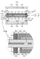
以下、本発明の実施形態について説明する。本発明の実施形態である燃料電池用単体セルの断面図を図1に示す。図1において、単体セル100を構成する多孔シート113の中心領域121(以下、領域1という)には、貫通孔117が多数個形成されている。この領域1を取り巻く周囲には貫通孔117が形成されていない領域2が配設されている。ここに、領域1と領域2とを区画する仕切り線118を仮想的に定義する。この多孔シート113の平面図を図2に示す。
Hereinafter, embodiments of the present invention will be described. A cross-sectional view of a unit cell for a fuel cell according to an embodiment of the present invention is shown in FIG. In FIG. 1, a large number of through
そして、この貫通孔117には、イオン交換樹脂が充填されることで、充填層114が形成されている。また、この多孔シート113の両外面には同一のイオン交換樹脂からなる樹脂層125が連設されることで固体高分子電解質膜111が形成されている。この固体高分子電解質膜111の縦断面図を図4に示す。
The through
また、固体高分子電解質膜111の両外面には、それぞれ触媒層127、128が接合されている。この触媒層127、128は、固体高分子電解質膜111の中心部分に形成されており、その周辺には触媒層127、128の接合されない部分が残されている。
Further, catalyst layers 127 and 128 are bonded to both outer surfaces of the solid
そして、これら固体高分子電解質膜111及び触媒層127、128により、膜触媒層接合体131が構成されており、膜触媒層接合体131の触媒層127、128側の両外面には、それぞれガス拡散層133、134が配設されている。このガス拡散層133、134は、触媒層127、128から出入りする電子を効率よく集電するために触媒層127、128と同等か若しくはそれ以上の大きさを有している。
A membrane
即ち、ガス拡散層133、134は、この触媒層127、128の表面のみならず、側面をも被覆するように配設されており、ガス拡散層133、134は固体高分子電解質膜111と接触面133aで面接触されている。ガス拡散層133、134は、カーボンペーパーやカーボンクロス等で形成されている。また、触媒層127、128の外縁からガス拡散層133、134の外縁までが領域2に位置するように配置されている。ただし、図示は省略するが、ガス拡散層133、134は、触媒層127、128の表面のみに平面状に配設され、側面を被覆しないようにされても良い。
That is, the gas diffusion layers 133 and 134 are disposed so as to cover not only the surfaces of the catalyst layers 127 and 128 but also the side surfaces, and the gas diffusion layers 133 and 134 are in contact with the solid
そして、これら膜触媒層接合体131及びガス拡散層133、134により、膜電極接合体137が構成されており、この膜電極接合体137のガス拡散層133、134側の両外面には、セパレータ141、142との間にガス流路147、148が形成されるようになっている。このとき、セパレータ141、142は、固体高分子電解質膜111全面と同じ大きさを有しており、触媒層127、128と正対する部分には、それぞれ凹状の溝145、146が刻設されている。
The membrane /
そして、この溝145、146は、セパレータ141、142及び膜電極接合体137が締め付けられたときに、ガス流路147、148を形成するようになっている。更に、膜触媒層接合体131のうち触媒層127、128及びガス拡散層133、134が接合されていない部分には、燃料ガスならびに酸化剤ガスが外部に漏れないようにシールするためにガスケット153、154が配置されており、ガス流路147、148を外部に対して密封するようになっている。ガスケット153、154の触媒層27、28側の内縁部300は、領域2に位置するように配置されている。なお、図1中のA−A矢視図を図3に示す。
The
かかる構成において、触媒層127及び触媒層128の大きさは、一般には、製造上多少異なっている。このため、図1中に示す触媒層127と触媒層128の端縁も現実には多少ずれが生じている。また、この触媒層127、128を被覆するガス拡散層133、134の端縁も同様に多少ずれが生じている。そして、この触媒層127の端縁と触媒層128の端縁のうち、より領域1に近い方を触媒層端縁130と定義する(図1の例では、触媒層128の端縁の方が触媒層127の端縁よりも領域1に近いので、触媒層128の端縁を触媒層端縁130とする)。一方、ガス拡散層133の端縁とガス拡散層134の端縁のうち、より領域1から遠い方をガス拡散層端縁140と定義する(図1の例では、ガス拡散層133の端縁の方がガス拡散層134の端縁よりも領域1から遠いので、ガス拡散層133の端縁をガス拡散層端縁140とする)。
In such a configuration, the sizes of the
このとき、仕切り線118と触媒層端縁130との距離は、1〜12mm程度が良く、より好ましくは1〜6mm程度であり、更に好ましくは2〜4mm程度である。1mmより小さいと気体が領域2を迂回して領域1を透過するため、膜の劣化抑制効果が十分に発揮されず、12mmより大きいと有効利用されない触媒層部分が増え発電効率が低下して好ましくない。
At this time, the distance between the
また、ガスケット153、154の内縁部300は、領域2に位置するように配置されるが、領域2のほぼ中央に位置されるのが望ましい。
ガスケット153、154の内縁部300が貫通孔の形成されていない領域2に位置するように配置したので、ガスケット接合時に固体高分子電解質膜111に圧力が強くかかったり、運転中のクリープによって固体高分子電解質膜111が一部損傷を受けてもガスリークの増大が抑制され、局部的な燃焼反応などによる固体高分子電解質膜111の劣化や電極の短絡を防ぐことが可能となる。このことにより、長寿命の燃料電池用の膜電極接合体137を提供することができる。
Further, the
Since the
なお、領域2のガス透過性は、用いるシートの材質と厚み、イオン交換樹脂層の厚み、ガスの種類によって変わるが、領域1のガス透過性の1/2以下であることが好ましく、より好ましくは1/10以下である。領域2のガス透過性が、領域1のガス透過性の1/2より大きいと、領域2におけるガスリーク抑制の効果が十分に発揮されなくなるので好ましくない。
The gas permeability of region 2 varies depending on the material and thickness of the sheet used, the thickness of the ion exchange resin layer, and the type of gas, but is preferably less than or equal to ½ of the gas permeability of
また、多孔シート113の材質としては、実質的にイオン交換基を有しておらず、90℃の熱水に浸漬後の含水率が5%以下のものを用いることが好ましい。5%より大きいと触媒層127、128を接合する際や、燃料電池運転時の押し付け圧力に対してクリープしやすくなり固体高分子電解質膜111が損傷し、また気体透過性も高くなるので好ましくない。
Moreover, as a material of the
多孔シート113の貫通孔117の1個あたりの平均面積は1×10⁻³〜20mm2が好ましく、更には8×10⁻³〜4mm2程度、特に1.5×10⁻²〜1mm2程度であることが好ましい。例えば、貫通孔117の1個あたりの平均面積が小さすぎると、開口率を一定範囲に維持しようとすれば単位面積あたりの貫通孔117の数が非常に多くなるために生産性が低くなったり、イオン交換樹脂の充填が困難になるおそれがある。
The average area per through
一方、貫通孔117の1個あたりの平均面積が大きすぎると、得られる固体高分子電解質膜111を均一に補強することができず、結果としてその強度が不十分となるおそれがある。そのため、貫通孔117の1個あたりの平均面積を1×10⁻³〜20mm2程度とすれば、固体高分子電解質膜111に実用上均一で十分な強度を持たせることができ、更に生産性も高く、十分なイオン伝導性を持たせることができる。
On the other hand, if the average area per through-
また、このような貫通孔117が形成された多孔シート113の中心領域121における開口率は30〜80%であることが好ましく、更には50〜75%、特には62〜70%が好ましい。例えば、開口率が低すぎると、イオン伝導性が妨げられるおそれがあるからである。一方、開口率が高すぎると、得られる固体高分子電解質膜111を十分に補強することができず、その強度が不十分となるおそれがあるからである。
Moreover, it is preferable that the aperture ratio in the center area |
そして、このような貫通孔117の大きさや形状は全て均一とするようにしても良いが、2種以上の大きさや形状を有する孔が混在しても良い。また、貫通孔117の形状は、特に制限されないが、角があるとそれが切りかけとなり補強体としての強度が低下するおそれがあるため、円形あるいは角がない形状であることが好ましい。
In addition, the size and shape of the through
貫通孔117の形成に際しては、多孔シート113を機械的に穴あけ加工する方法や、レーザー光線を用いて多孔シート113を形成する方法等があるが、機械的に穴あけ加工する方法は量産性に優れており好ましい方法である。例えば、機械的に打ち抜く方法では、多孔シート113を数十枚から数千枚重ねて、これらに対し数百から数万の貫通孔117を一度に形成できる抜き型を用いることで、短時間で多数の貫通孔117を加工することが可能となる。
In forming the through
また、ドリル加工も適しており、多孔シート113を数十枚から数千枚重ねて、これらに対し多軸NCドリル機を用いて孔あけすることにより、短時間で多数の貫通孔117を加工することができ、低コストで生産することができる。そして、このような多孔シート113の厚さは、これを有する固体高分子電解質膜111を固体高分子型燃料電池に適用する場合には、3〜50μmであることが好ましく、特に5〜30μmであることが好ましい。
Drilling is also suitable, and dozens or thousands of
例えば、多孔シート113が薄すぎると、得られる固体高分子電解質膜111を十分に補強できないおそれがあり、また領域2で触媒層端部でのガスリーク遮断性を十分に確保できないおそれがあるからである。一方、多孔シート113が厚すぎると、得られる固体高分子電解質膜111も厚くなりすぎてしまい、イオン伝導抵抗が高くなり抵抗損失が大きくなって十分な性能が得られないおそれがあるからである。
For example, if the
また、特に限定されるものではないが、得られる固体高分子電解質膜111を均一に補強できるようにするために、多孔シート113の膜厚は均一であることが望ましい。このような多孔シート113の貫通孔117には、イオン交換樹脂が充填されるようになっており、これにより、多孔シート113に充填層114が形成されるようになっている。
Further, although not particularly limited, it is desirable that the thickness of the
ここで、充填層114を構成するイオン交換樹脂としては、スルホン酸基を有するパーフルオロカーボン重合体からなる陽イオン交換樹脂が好ましいが、陽イオン交換樹脂であれば、炭化水素系重合体や部分フッ素化された炭化水素系重合体からなる陽イオン交換樹脂等も使用できる。また、イオン交換樹脂は単一でも2種以上のイオン交換樹脂を混合したものでも良い。
Here, as the ion exchange resin constituting the packed
なお、この充填層114は、多孔シート113により補強されるため、充填層114自体の強度はあまり高くなくても良い。そのため、充填層114を構成するイオン交換樹脂は、得られる固体高分子電解質膜111の導電性を高めるために、強度が高くなくてもイオン交換容量が高いイオン交換樹脂を使用することが好ましい。
In addition, since this
そして、多孔シート113にイオン交換樹脂を充填する方法としては、特に限定されないが、例えばイオン交換樹脂が分散媒(溶媒)に分散(溶解)した液(以下、イオン交換樹脂含有液という)からキャスト法等により形成したキャスト膜を多孔シート113の両外面に熱圧着する方法や、イオン交換樹脂含有液を多孔シート113の一外面又は両外面に塗工する方法や、イオン交換樹脂含有液に多孔シート113を含浸させた後乾燥する方法等がある。
The method for filling the
更に、このような多孔シート113は、充填層114が形成された状態のままでも良いが、固体高分子電解質膜111の導電性を向上させるために、更に多孔シート113の少なくとも片面好ましくは両面にイオン交換樹脂のみからなる樹脂層125が形成されても良い。
Further, such a
そして、この場合、樹脂層125を構成するイオン交換樹脂は、充填層114を構成するイオン交換樹脂と同じ材料でも良いが、異なる材料でも良い。そして、異なる材料を用いる場合には、充填層114を構成するイオン交換樹脂よりも例えばイオン交換容量が低くても強度の高いイオン交換樹脂を使用することで、樹脂層125自体の強度を高めることができる。
In this case, the ion exchange resin constituting the
なお、樹脂層125は、図4に示すように、多孔シート113の両外面の全領域を覆うように形成されても良い。ただし、これに限られず、図5に示すように、多孔シート113の周辺部分115を一部残して中心領域121を全て覆うように中心領域121の面積より大きく形成されても良い。
Note that the
そして、この樹脂層125の形成に際しては、多孔シート113に充填層114を形成する際の塗工により形成しても良いし、別途樹脂層125を作製しておいてホットプレス等により多孔シート113上に接合しても良い。また、塗工により形成された樹脂層125と、別途作製した樹脂層125との両方で構成されても良い。
In forming the
更に、多孔シート113上にイオン交換樹脂含有液を塗布して樹脂層125を形成しても良いし、また、別途キャスト法等により樹脂からなる層を作製しておき、この層を多孔シート113の両面に配置し、ホットプレスすることにより充填層114と樹脂層125を同時に形成しても良い。また、これらの方法を繰り返し行ったり、組み合わせて行ったりすることで、樹脂層125を形成しても良い。
Furthermore, a
そして、以上のようにして充填層114や樹脂層125が形成された多孔シート113は、図1に示した固体高分子電解質膜111を構成するようになっている。固体高分子電解質膜111は複数枚の多孔シート113を有していても良く、その場合には、それぞれ異なるポリマーからなる多孔シート113を積層させても良い。また、この場合、隣接する多孔シート113間で、樹脂層125が形成されていない面同士が直接接触されるものがあっても良いし、樹脂層125同士が接触されるものがあっても良い。
The
なお、図6〜図8には、本発明の実施形態である燃料電池用単体セルの第2の形態を示す。
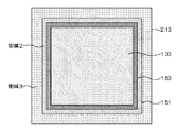
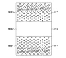
図6の燃料電池用単体セルの断面図において、単体セル200の多孔シート213は、領域2の更に外周部に、複数の貫通孔117が形成された領域3が設けられている。この場合の多孔シート213の平面図を図7に、図6中のB−B矢視図を図8に示す。
6 to 8 show a second form of the unit cell for a fuel cell which is an embodiment of the present invention.
In the cross-sectional view of the unit cell for a fuel cell in FIG. 6, the
ここに、領域2と領域3とを区画する仕切り線151を仮想的に定義する。即ち、領域2は図7に示すように額縁状に形成されている。このように、領域3を設けることにより、膜周辺部においても多孔シート213の貫通孔117を介して両表面のイオン交換樹脂がつながり、多孔シート213とイオン交換樹脂との剥がれを予防することができる。
Here, a
ガスケット153、154の内縁部300が、領域2の幅内の中間部に位置することが望ましい。また、この領域2の幅は2〜24mm程度が良く、より好ましくは3〜12mm程度であり、更に好ましくは4〜8mm程度である。
It is desirable that the
更に、領域1と領域2の境界部、領域2と領域3の境界部は、ともに又はいずれか一方の領域において、図9に示すように領域2に近づくにつれて貫通孔117の1個あたりの平均面積が徐々に小さくされるのが望ましい。このように開口率を徐々に小さくすることにより、領域1と領域2の境界、領域2と領域3の境界に応力が集中することを防ぎことができる。同様の理由から、図10に示すように、貫通孔117の数が徐々に減少されても良い。
Furthermore, the boundary part between the
なお、本発明で用いられる多孔シート材料(構成材料)は、ポリテトラフルオロエチレン、テトラフルオロエチレン−ヘキサフルオロプロピレン共重合体、テトラフルオロエチレン−パーフルオロアルコキシエチレン共重合体、テトラフルオロエチレン−エチレン共重合体、ポリエチレン、ポリプロピレン、ポリエーテルアミド、ポリエーテルイミド、ポリエーテルケトン、ポリエーテルエーテルケトン、ポリスルフォン、ポリエーテルスルフォン、ポリフェニレンスルフィド、ポリフェニレンオキシド、ポリフォスファゼン、ポリアリレート、ポリイミド、ポリイミドアミド、及び、ポリベンズイミダゾールからなる群より選択される少なくとも1種である。 The porous sheet material (constituent material) used in the present invention is polytetrafluoroethylene, tetrafluoroethylene-hexafluoropropylene copolymer, tetrafluoroethylene-perfluoroalkoxyethylene copolymer, tetrafluoroethylene-ethylene copolymer. Polymer, polyethylene, polypropylene, polyetheramide, polyetherimide, polyetherketone, polyetheretherketone, polysulfone, polyethersulfone, polyphenylene sulfide, polyphenylene oxide, polyphosphazene, polyarylate, polyimide, polyimideamide, and , At least one selected from the group consisting of polybenzimidazole.
この多孔シート113、213は材質によっては接着性が小さいため、表面処理されているとイオン交換樹脂との接着性が高くなり好ましい。表面処理の方法は特には限定されないが、化学エッチング処理やコロナ放電処理、プラズマ表面処理などが好適に用いられる。
Since the
[実施例1]
(膜の作製)
厚さ12μm、200mm角のポリフェニレンスルフィドフィルム(商品名:トレリナ3030−12、東レ社製)の主面中央部分に、多軸ドリルによりφ300μmの貫通孔(1個あたりの平均面積が約0.071mm2)を中心間距離が350μmになるように千鳥配列で213280個開口させ、開口率がおよそ67%で150mm角の領域1と、その外側に開口部を有していない領域2を有する多孔シート113を作製した。
[Example 1]
(Membrane preparation)
At the center of the main surface of a polyphenylene sulfide film (trade name: Torelina 3030-12, manufactured by Toray Industries, Inc.) having a thickness of 12 μm and 200 mm square, a φ300 μm through-hole (average area per piece is about 0.071 mm) 2 ) perforated sheet having 21280 apertures in a staggered arrangement so that the center-to-center distance is 350 μm, having an aperture ratio of approximately 67% and a 150 mm
次に、シリコーン系離型剤で表面を処理した厚さ約100μmのポリエチレンテレフタレート製基材(以下、これと同様の基材をPET基材という)の上にCF2=CF2に基づく繰り返し単位とCF2=CF−OCF2CF(CF3)−OCF2CF2SO3Hに基づく繰り返し単位とからなるイオン交換樹脂の分散液(イオン交換容量:1.1ミリ当量/グラム乾燥樹脂、商品名:フレミオン、旭硝子社製、以下、分散液aという)をダイコート法で総厚みが15μmで200mm角になるように塗工した後、90℃で乾燥させた。そして、これらを2枚製作し、分散液aが塗布された側をそれぞれ多孔シート113側に当てて挟み、約150℃で20分間熱プレスし、図2に示す固体高分子電解質膜111を得た。
Next, a repeating unit based on CF 2 = CF 2 on a polyethylene terephthalate base material (hereinafter referred to as a PET base material) having a thickness of about 100 μm whose surface has been treated with a silicone release agent. Of ion exchange resin consisting of repeating units based on CF 2 ═CF—OCF 2 CF (CF 3 ) —OCF 2 CF 2 SO 3 H (ion exchange capacity: 1.1 meq / g dry resin, commercial product Name: Flemion, manufactured by Asahi Glass Co., Ltd., hereinafter referred to as “dispersion a”) was applied by a die coating method to a total thickness of 15 μm and a 200 mm square, and then dried at 90 ° C. Then, two of these are manufactured, and the side on which the dispersion liquid a is applied is respectively sandwiched between the
(含水率の測定)
厚さ12μm、200mm角のポリフェニレンスルフィドフィルム(商品名:トレリナ3030−12、東レ社製)を90℃の熱水に16時間浸漬後、取り出し、フィルム表面の水分を濾紙で拭き取り、重量を測定した。測定後25℃で窒素を16時間流し、乾燥させ乾燥重量を測定した。含水率は0.2%であった。
(Measurement of moisture content)
A 12 μm thick, 200 mm square polyphenylene sulfide film (trade name: Torelina 3030-12, manufactured by Toray Industries, Inc.) was immersed in hot water at 90 ° C. for 16 hours and then taken out. The moisture on the film surface was wiped off with filter paper and the weight was measured. . After the measurement, nitrogen was passed for 16 hours at 25 ° C., and the dry weight was measured. The water content was 0.2%.
(電極の接合)
更に、次のようにして、触媒層127、128を作製する。まず、分散液aと、白金をカーボン上に55質量%担持させた担持触媒とを、エタノールと水の混合分散媒(質量比で1:1)に分散させ、得られた固形分濃度14質量%の触媒分散液を固体高分子電解質膜111の片面の中心部に154mm角に塗工し、白金担持量が約0.4mg/cm2の触媒層128を形成しカソード極とする。
(Electrode bonding)
Further, the catalyst layers 127 and 128 are produced as follows. First, the dispersion a and a supported catalyst in which 55% by mass of platinum was supported on carbon were dispersed in a mixed dispersion medium (1: 1 by mass) of ethanol and water, and the resulting solid content concentration was 14%. % Catalyst dispersion is applied to the central part of one side of the solid
次に、分散液aと、白金とルテニウムの合金をカーボン上に50質量%担持させた担持触媒とを、エタノールと水の混合分散媒(質量比で1:1)に分散させ、得られた固形分濃度14質量%の触媒分散液を固体高分子電解質膜111のもう一方の面の中心部に154mm角に塗工して白金担持量が約0.3mg/cm2の触媒層127を形成してアノード極とし、膜触媒層接合体131を作製する。そして、この膜触媒層接合体131に対して154mm角の触媒層128がその中央部分に配置されるようにして、外形をトムソン型で打ち抜き、165mm角の外形の膜触媒層接合体131を得る。
Next, the dispersion liquid a and a supported catalyst in which an alloy of platinum and ruthenium was supported by 50 mass% on carbon were dispersed in a mixed dispersion medium (mass ratio of 1: 1) of ethanol and water to obtain. A catalyst dispersion liquid with a solid content concentration of 14% by mass is applied to the center of the other surface of the solid
(電池セルへの組立てと評価)
次に、この膜触媒層接合体131の両表面中央にカーボンブラックとポリテトラフルオロエチレン粒子とからなる厚さ約10μmの導電層を厚さ約300μmのカーボンクロス基材上に形成したガス拡散層156mm角をその導電層が膜触媒層接合体131に接するよう配置する。そしてこれを反応ガス供給用のガス流路147、148を備えた一対のセパレータ141、142間ならびにシールする内寸法が158mm角であるフッ素ゴムのガスケット153、154に挟み込んで有効電極面積が225cm2である燃料電池用の単セル100を得る。
(Assembly and evaluation of battery cells)
Next, a gas diffusion layer in which a conductive layer made of carbon black and polytetrafluoroethylene particles having a thickness of about 10 μm is formed on a carbon cloth substrate having a thickness of about 300 μm at the center of both surfaces of the membrane
そして、この単セル100のセル温度を90℃に制御し、アノード極側に水素ガス、カソード極側に空気をそれぞれ供給する。この供給するガスは、水素ガスの利用率を80%、空気の利用率を50%とし、供給するガスの露点がそれぞれ70℃となるように加湿してから燃料電池に供給する。その結果どの条件でも安定して運転させることができる。セル温度90℃で電流密度を0.15A/cm2として連続運転するときの経過時間とセル電圧の関係を図11に示す。
Then, the cell temperature of the
[実施例2]
(膜の作製)
厚さ12μm、200mm角のポリフェニレンスルフィドフィルム(商品名:トレリナ3030−12、東レ社製)の主面中央部分に、多軸ドリルによりφ300μmの貫通孔117(1個あたりの平均面積が約0.071mm2)を中心間距離が350μmになるように千鳥配列で213280個開口させ、開口率がおよそ67%で150mm角の領域1と162mm角より外側に同じく多軸ドリルによりφ300μmの貫通孔117を中心間距離が350μmの千鳥配列で開口させ、開口率がおよそ67%の領域3をつくり、開口を有さない領域2の幅が7mmの多孔シート213を作製する。
[Example 2]
(Membrane preparation)
At the center of the main surface of a polyphenylene sulfide film (trade name: Torelina 3030-12, manufactured by Toray Industries, Inc.) having a thickness of 12 μm and 200 mm square, through-
そして、この多孔シート213に対して実施例1と同様にして、分散液aが塗布されたPET基材を分散液aが塗布された側をそれぞれ多孔シート213側に当てて挟み、約150℃で20分間熱プレスし、図7に示す固体高分子電解質膜211(図2の固体高分子電解質膜111に相当する)を得た。
Then, in the same manner as in Example 1, the
(電極の接合)
更にこの固体高分子電解質膜211に実施例1と同様にしてカソード極とアノード極を形成し、外形をトムソン型で打ち抜き、165mm角の外形の膜触媒層接合体231(図2の膜触媒層接合体131に相当する)を得る。
(Electrode bonding)
Further, a cathode electrode and an anode electrode were formed on the solid
(電池セルへの組立てと評価)
次に、この膜触媒層接合体231に対して実施例1と同様にガス拡散層133、134を配置し、有効電極面積が225cm2である燃料電池用の単セル200を得る。そして、この単セル200をセル温度を90℃に制御し、アノード極側に水素ガス、カソード極側に空気をそれぞれ供給する。この供給するガスは、水素ガスの利用率を80%、空気の利用率を50%とし、供給するガスの露点がそれぞれ70℃となるように加湿してから燃料電池に供給する。その結果どの条件でも安定して運転させることができる。セル温度90℃で電流密度を0.15A/cm2として連続運転するときの経過時間とセル電圧の関係を図11に示す。
(Assembly and evaluation of battery cells)
Next, gas diffusion layers 133 and 134 are disposed on the membrane
[実施例3]
(膜の作製)
厚さ25μmのパーフルオロアルコキシエチレン重合体からなるフィルム(商品名:トヨフロンPFA、東レ社製)の主面中心に、多軸ドリルによりφ300μmの貫通孔117(1個あたりの平均面積が約0.071mm2)を中心間距離が350μmになるように千鳥配列で213280個開口させ、開口率がおよそ67%で150mm角の領域1と162mm角より外側に同じく多軸ドリルによりφ300μmの貫通孔117を中心間距離が350μmの千鳥配列で開口させ、開口率がおよそ67%の領域3をつくり、実施例2と同様に開口を有さない領域2の幅が7mmの多孔シート213を作製する。
[Example 3]
(Membrane preparation)
In the center of the main surface of a film (trade name: Toyoflon PFA, manufactured by Toray Industries, Inc.) made of a perfluoroalkoxyethylene polymer having a thickness of 25 μm, a through
そして、この多孔シート213に対して実施例1と同様にして、分散液aが塗布されたPET基材を分散液aが塗布された側をそれぞれ多孔シート213側に当てて挟み、約150℃で20分間熱プレスし、図7に示す固体高分子電解質膜211を得た。
Then, in the same manner as in Example 1, the
(含水率の測定)
厚さ25μmのパーフルオロアルコキシエチレン重合体からなるフィルム(商品名:トヨフロンPFA、東レ社製)を90℃の熱水に16時間浸漬後、取り出し、フィルム表面の水分を濾紙で拭き取り、重量を測定した。測定後25℃で窒素を16時間流し、乾燥させ乾燥重量を測定した。含水率は0.1%であった。
(Measurement of moisture content)
A film made of a perfluoroalkoxyethylene polymer having a thickness of 25 μm (trade name: Toyoflon PFA, manufactured by Toray Industries, Inc.) is immersed in hot water at 90 ° C. for 16 hours and then taken out. The moisture on the film surface is wiped off with filter paper and the weight is measured. did. After the measurement, nitrogen was passed for 16 hours at 25 ° C., and the dry weight was measured. The water content was 0.1%.
(電極の接合)
更にこの固体高分子電解質膜211に実施例1と同様にしてカソード極とアノード極を形成し、外形をトムソン型で打ち抜き、165mm角の外形の膜触媒層接合体231を得る。
(Electrode bonding)
Further, a cathode electrode and an anode electrode are formed on the solid
(電池セルへの組立てと評価)
次に、この膜触媒層接合体231に対して実施例1と同様にガス拡散層133、134を配置し、有効電極面積が225cm2である燃料電池用の単セル200を得る。そして、この単セル200をセル温度90℃に制御し、アノード極側に水素ガス、カソード極側に空気をそれぞれ供給する。この供給するガスは、水素ガスの利用率を80%、空気の利用率を50%とし、供給するガスの露点がそれぞれ70℃となるように加湿してから燃料電池に供給する。その結果どの条件でも安定して運転させることができる。セル温度90℃で電流密度を0.15A/cm2として連続運転するときの経過時間とセル電圧の関係を図11に示す。
(Assembly and evaluation of battery cells)
Next, gas diffusion layers 133 and 134 are disposed on the membrane
[比較例1]
CF2=CF2に基づく繰り返し単位とCF2=CF−OCF2CF(CF3)−OCF2CF2SO3Hに基づく繰り返し単位とからなる厚さ30μmのイオン交換膜(イオン交換容量:1.1ミリ当量/グラム乾燥樹脂、商品名:フレミオンSH−30、旭硝子社製)を膜として用いた(以下、この膜を膜M1という)。
[Comparative Example 1]
CF 2 = repeating unit CF 2 = CF-OCF 2 CF (CF 3) based on CF 2 -OCF 2 CF 2 SO 3 ion exchange membrane having a thickness of 30μm consisting of repeating units based on H (ion exchange capacity: 1 .1 milliequivalent / gram dry resin, trade name: Flemion SH-30, manufactured by Asahi Glass Co., Ltd.) was used as the membrane (hereinafter this membrane is referred to as membrane M1).
(電極の接合)
そして、この膜M1に対して実施例1と同様にしてカソード極とアノード極を形成し、外形をトムソン型で打ち抜き、165mm角の外形の膜触媒層接合体CCM1を得た。
(Electrode bonding)
Then, a cathode electrode and an anode electrode were formed on the membrane M1 in the same manner as in Example 1, and the outer shape was punched out by a Thomson type to obtain a membrane catalyst layer assembly CCM1 having an outer shape of 165 mm square.
(電池セルへの組立てと評価)
次に、この膜触媒層接合体CCM1に対して実施例1と同様にガス拡散層133、134を配置し、有効電極面積が225cm2である燃料電池用の単セルを得た。そして、この単セルをセル温度90℃に制御し、アノード極側に水素ガス、カソード極側に空気をそれぞれ供給する。この供給するガスは、水素ガスの利用率を80%、空気の利用率を50%とし、供給するガスの露点がそれぞれ70℃となるように加湿してから燃料電池に供給する。その結果どの条件でも安定して運転させることができる。セル温度90℃で電流密度を0.15A/cm2として連続運転するときの経過時間とセル電圧の関係を図11に示す。
(Assembly and evaluation of battery cells)
Next, gas diffusion layers 133 and 134 were disposed on the membrane catalyst layer assembly CCM1 in the same manner as in Example 1 to obtain a single cell for a fuel cell having an effective electrode area of 225 cm 2 . The single cell is controlled at a cell temperature of 90 ° C., and hydrogen gas is supplied to the anode electrode side and air is supplied to the cathode electrode side. The supplied gas has a hydrogen gas utilization rate of 80% and an air utilization rate of 50%, and is supplied to the fuel cell after being humidified so that the dew point of the supplied gas is 70 ° C., respectively. As a result, stable operation can be achieved under any conditions. FIG. 11 shows the relationship between the elapsed time and the cell voltage when continuously operating at a cell temperature of 90 ° C. and a current density of 0.15 A / cm 2 .
このように、シート膜に領域1、2を設けず、無補強でかつイオン交換膜のみから形成した場合には、経過時間が600時間を超えたあたりで、急激にセル電圧が降下することが分かる。
As described above, when the sheet membrane is not provided with the
[比較例2]
厚さ12μm、200mm角のポリフェニレンスルフィドフィルム(商品名:トレリナ3030−12、東レ社製)の主面中心に、多軸ドリルによりφ300μmの貫通孔117(1個あたりの平均面積が約0.071mm2)を中心間距離が350μmになるように千鳥配列で275232個開口させ、開口率がおよそ67%で170mmの領域を有する多孔シートを作製した。そして、この多孔シートに対して実施例1と同様にして、分散液aが塗布されたPET基材を分散液aが塗布された側をそれぞれ多孔シート側に当てて挟み、約150℃で20分間熱プレスし、固体高分子電解質膜を得た。
[Comparative Example 2]
At the center of the main surface of a polyphenylene sulfide film (trade name: Torelina 3030-12, manufactured by Toray Industries, Inc.) with a thickness of 12 μm and 200 mm square, through holes 117 (average area of about 0.071 mm per piece) of φ300 μm by a multi-axis drill 2 ) was opened in a staggered manner so that the center-to-center distance was 350 μm, and a porous sheet having an aperture ratio of about 67% and a region of 170 mm was produced. Then, in the same manner as in Example 1, the porous substrate was sandwiched with the PET substrate coated with the dispersion liquid a with the side coated with the dispersion liquid a against the porous sheet side. The solid polymer electrolyte membrane was obtained by hot pressing for a minute.
(電極の接合)
そして、この固体高分子電解質膜に対して実施例1と同様にしてカソード極とアノード極を形成し、外形をトムソン型で打ち抜き、165mm角の外形の膜触媒層接合体CCM2を得た。
(Electrode bonding)
Then, a cathode electrode and an anode electrode were formed on the solid polymer electrolyte membrane in the same manner as in Example 1, and the outer shape was punched out by a Thomson type to obtain a membrane catalyst layer assembly CCM2 having a 165 mm square shape.
(電池セルへの組立てと評価)
次に、この膜触媒層接合体CCM2に対して実施例1と同様にガス拡散層133、134を配置し、有効電極面積が225cm2である燃料電池用の単セルを得た。そして、この単セルのセル温度を90℃に制御し、アノード極側に水素ガス、カソード極側に空気をそれぞれ供給する。この供給するガスは、水素ガスの利用率を80%、空気の利用率を50%とし、供給するガスの露点がそれぞれ70℃となるように加湿してから燃料電池に供給する。その結果どの条件でも安定して運転させることができる。セル温度90℃で電流密度を0.15A/cm2として連続運転するときの経過時間とセル電圧の関係を図11に示す。
(Assembly and evaluation of battery cells)
Next, gas diffusion layers 133 and 134 were disposed on the membrane-catalyst layer assembly CCM2 in the same manner as in Example 1 to obtain a single cell for a fuel cell having an effective electrode area of 225 cm 2 . Then, the cell temperature of this single cell is controlled to 90 ° C., and hydrogen gas is supplied to the anode electrode side and air is supplied to the cathode electrode side. The supplied gas has a hydrogen gas utilization rate of 80% and an air utilization rate of 50%, and is supplied to the fuel cell after being humidified so that the dew point of the supplied gas is 70 ° C., respectively. As a result, stable operation can be achieved under any conditions. FIG. 11 shows the relationship between the elapsed time and the cell voltage when continuously operating at a cell temperature of 90 ° C. and a current density of 0.15 A / cm 2 .
このように、多孔シートには、領域1のみが形成され、領域2が形成されていない状態なので、図11に示すように、経過時間が1200時間を超えたあたりで、急激にセル電圧が降下する。
As described above, since only the
1、100、200 単体セル
11、111、211 固体高分子電解質膜
11a 固体高分子電解質膜の両外面
113、213 多孔シート
114 充填層
117 貫通孔
118、151 仕切り線
121 中心領域
125 樹脂層
27、28、127、128 触媒層
130 触媒層端縁
31、131、231 膜触媒層接合体
31a 膜触媒層接合体の両外面
33、34、133、134 ガス拡散層
33a、133a 接触面
37、137、237 膜電極接合体
37a 膜触媒層接合体の両外面
140 ガス拡散層端縁
41、42、141、142 セパレータ
45、46、145、146 溝
47、48、147、148 ガス流路
53、54、153、154 ガスケット
300 ガスケットの触媒層側の内縁部
1, 100, 200
Claims (8)
該固体高分子電解質膜の両面に配設される触媒を含む触媒層と該触媒層を支持するガス拡散層とからなり、外周部が前記固体高分子電解質膜の外周部の内側に配置される電極と、
前記固体高分子電解質膜をその両面から隣接して挟み込み内縁部が前記電極の外周部の外側に位置するガスケットとからなる膜電極接合体において、
前記多孔シートは、前記貫通孔を介してプロトン導電性を有する第1の領域と、
前記貫通孔が形成されておらず、前記第1の領域の外周部に位置する第2の領域とを有し、
前記ガスケットの内縁部が前記第2の領域で前記高分子電解質膜と接するように配置されており、
前記貫通孔は、1個あたりの平均面積が1×10⁻³〜20mm2で、前記多孔シートの厚さ方向に対してほぼ平行に形成されており、
前記多孔シートにおける前記第1の領域は、前記貫通孔による開口率が30〜80%であることを特徴とする固体高分子形燃料電池用膜電極接合体。 A solid polymer electrolyte membrane having a porous layer formed of a porous sheet having a plurality of through holes and an ion exchange resin filled in the through holes;
The catalyst layer includes a catalyst layer disposed on both surfaces of the solid polymer electrolyte membrane and a gas diffusion layer that supports the catalyst layer, and the outer peripheral portion is disposed inside the outer peripheral portion of the solid polymer electrolyte membrane. Electrodes,
In a membrane electrode assembly comprising a gasket in which the solid polymer electrolyte membrane is sandwiched adjacent from both sides and an inner edge portion is located outside the outer peripheral portion of the electrode,
The porous sheet has a first region having proton conductivity through the through hole;
The through hole is not formed, and has a second region located on the outer periphery of the first region,
An inner edge of the gasket is disposed in contact with the polymer electrolyte membrane in the second region;
Each of the through holes has an average area of 1 × 10 −3 to 20 mm 2 and is formed substantially parallel to the thickness direction of the porous sheet.
The membrane electrode assembly for a polymer electrolyte fuel cell, wherein the first region in the porous sheet has an aperture ratio of 30 to 80% due to the through holes.
該固体高分子電解質膜の両面に配設される触媒を含む触媒層と該触媒層を支持するガス拡散層とからなり、外周部が前記固体高分子電解質膜の外周部の内側に配置される電極と、
前記固体高分子電解質膜をその両面から隣接して挟み込み内縁部が前記電極の外周部の外側に位置するガスケットとからなる膜電極接合体において、
前記多孔シートは、前記貫通孔を介してプロトン導電性を有する第1の領域と、
前記貫通孔が形成されておらず、前記第1の領域の外周部に位置する第2の領域と、
該第2の領域の更に外周部に前記貫通孔が形成され該貫通孔を介してプロトン導電性を有する第3の領域を有し、
前記ガスケットの内縁部が前記第2の領域で前記高分子電解質膜と接するように配置されており、
前記貫通孔は、1個あたりの平均面積が1×10⁻³〜20mm2で、前記多孔シートの厚さ方向に対してほぼ平行に形成されており、
前記多孔シートにおける前記第1の領域は、前記貫通孔による開口率が30〜80%であることを特徴とする固体高分子形燃料電池用膜電極接合体。 A solid polymer electrolyte membrane having a porous layer formed of a porous sheet having a plurality of through holes and an ion exchange resin filled in the through holes;
The catalyst layer includes a catalyst layer disposed on both surfaces of the solid polymer electrolyte membrane and a gas diffusion layer that supports the catalyst layer, and the outer peripheral portion is disposed inside the outer peripheral portion of the solid polymer electrolyte membrane. Electrodes,
In a membrane electrode assembly comprising a gasket in which the solid polymer electrolyte membrane is sandwiched adjacent from both sides and an inner edge portion is located outside the outer peripheral portion of the electrode,
The porous sheet has a first region having proton conductivity through the through hole;
A second region that is not formed with the through-hole and is located on an outer periphery of the first region;
The through hole is formed in the outer peripheral portion of the second region, and the third region has proton conductivity through the through hole.
An inner edge of the gasket is disposed in contact with the polymer electrolyte membrane in the second region;
Each of the through holes has an average area of 1 × 10 −3 to 20 mm 2 and is formed substantially parallel to the thickness direction of the porous sheet.
The membrane electrode assembly for a polymer electrolyte fuel cell, wherein the first region in the porous sheet has an aperture ratio of 30 to 80% due to the through holes.
Priority Applications (1)
| Application Number | Priority Date | Filing Date | Title |
|---|---|---|---|
| JP2005250376A JP5087216B2 (en) | 2004-08-30 | 2005-08-30 | Membrane electrode assembly for polymer electrolyte fuel cell and polymer electrolyte fuel cell |
Applications Claiming Priority (3)
| Application Number | Priority Date | Filing Date | Title |
|---|---|---|---|
| JP2004250285 | 2004-08-30 | ||
| JP2004250285 | 2004-08-30 | ||
| JP2005250376A JP5087216B2 (en) | 2004-08-30 | 2005-08-30 | Membrane electrode assembly for polymer electrolyte fuel cell and polymer electrolyte fuel cell |
Publications (2)
| Publication Number | Publication Date |
|---|---|
| JP2006100268A true JP2006100268A (en) | 2006-04-13 |
| JP5087216B2 JP5087216B2 (en) | 2012-12-05 |
Family
ID=36239846
Family Applications (1)
| Application Number | Title | Priority Date | Filing Date |
|---|---|---|---|
| JP2005250376A Expired - Fee Related JP5087216B2 (en) | 2004-08-30 | 2005-08-30 | Membrane electrode assembly for polymer electrolyte fuel cell and polymer electrolyte fuel cell |
Country Status (1)
| Country | Link |
|---|---|
| JP (1) | JP5087216B2 (en) |
Cited By (2)
| Publication number | Priority date | Publication date | Assignee | Title |
|---|---|---|---|---|
| KR20150068370A (en) * | 2012-10-09 | 2015-06-19 | 옥시너지 엘티디 | Electrode assembly and method for its preparation |
| CN113745610A (en) * | 2020-05-28 | 2021-12-03 | 丰田自动车株式会社 | Fuel cell unit |
Citations (10)
| Publication number | Priority date | Publication date | Assignee | Title |
|---|---|---|---|---|
| JPH11310649A (en) * | 1998-04-28 | 1999-11-09 | Tokuyama Corp | Cation exchange membrane and its use |
| JP2000215903A (en) * | 1999-01-25 | 2000-08-04 | Toshiba Corp | Solid high-molecular electrolyte type fuel cell |
| WO2000054351A1 (en) * | 1999-03-08 | 2000-09-14 | Center For Advanced Science And Technology Incubation, Ltd. | Electrolytic membrane for fuel cell and its manufacturing method, and fuel cell and its manufacturing method |
| WO2001091213A1 (en) * | 2000-05-24 | 2001-11-29 | Sony Corporation | Electric energy generator and method for manufacturing the same |
| JP2002083612A (en) * | 2000-09-07 | 2002-03-22 | Takehisa Yamaguchi | Electrolyte film and its manufacturing method, and fuel cell and its manufacturing method |
| WO2002059996A1 (en) * | 2001-01-26 | 2002-08-01 | Toray Industries, Inc. | Polymer electrolyte film and method for preparation of the same, and solid polymer type fuel cell using the same |
| JP2002313363A (en) * | 2001-04-13 | 2002-10-25 | Mitsubishi Heavy Ind Ltd | Solid polymer electrolyte film and its manufacturing method |
| JP2003263999A (en) * | 2002-03-07 | 2003-09-19 | Toyota Central Res & Dev Lab Inc | Membrane electrode assembly and fuel cell and electrolytic cell having the same |
| WO2004019439A1 (en) * | 2002-07-25 | 2004-03-04 | Matsushita Electric Industrial Co., Ltd. | Electrolyte membrane, membrane electrode assembly using this and fuel cell |
| WO2004093228A1 (en) * | 2003-04-17 | 2004-10-28 | Asahi Glass Company, Limited | Solid polymer electrolyte membrane, membrane electrode assembly for solid polymer fuel cell, and method for producing solid polymer electrolyte membrane |
-
2005
- 2005-08-30 JP JP2005250376A patent/JP5087216B2/en not_active Expired - Fee Related
Patent Citations (10)
| Publication number | Priority date | Publication date | Assignee | Title |
|---|---|---|---|---|
| JPH11310649A (en) * | 1998-04-28 | 1999-11-09 | Tokuyama Corp | Cation exchange membrane and its use |
| JP2000215903A (en) * | 1999-01-25 | 2000-08-04 | Toshiba Corp | Solid high-molecular electrolyte type fuel cell |
| WO2000054351A1 (en) * | 1999-03-08 | 2000-09-14 | Center For Advanced Science And Technology Incubation, Ltd. | Electrolytic membrane for fuel cell and its manufacturing method, and fuel cell and its manufacturing method |
| WO2001091213A1 (en) * | 2000-05-24 | 2001-11-29 | Sony Corporation | Electric energy generator and method for manufacturing the same |
| JP2002083612A (en) * | 2000-09-07 | 2002-03-22 | Takehisa Yamaguchi | Electrolyte film and its manufacturing method, and fuel cell and its manufacturing method |
| WO2002059996A1 (en) * | 2001-01-26 | 2002-08-01 | Toray Industries, Inc. | Polymer electrolyte film and method for preparation of the same, and solid polymer type fuel cell using the same |
| JP2002313363A (en) * | 2001-04-13 | 2002-10-25 | Mitsubishi Heavy Ind Ltd | Solid polymer electrolyte film and its manufacturing method |
| JP2003263999A (en) * | 2002-03-07 | 2003-09-19 | Toyota Central Res & Dev Lab Inc | Membrane electrode assembly and fuel cell and electrolytic cell having the same |
| WO2004019439A1 (en) * | 2002-07-25 | 2004-03-04 | Matsushita Electric Industrial Co., Ltd. | Electrolyte membrane, membrane electrode assembly using this and fuel cell |
| WO2004093228A1 (en) * | 2003-04-17 | 2004-10-28 | Asahi Glass Company, Limited | Solid polymer electrolyte membrane, membrane electrode assembly for solid polymer fuel cell, and method for producing solid polymer electrolyte membrane |
Cited By (4)
| Publication number | Priority date | Publication date | Assignee | Title |
|---|---|---|---|---|
| KR20150068370A (en) * | 2012-10-09 | 2015-06-19 | 옥시너지 엘티디 | Electrode assembly and method for its preparation |
| KR102126597B1 (en) | 2012-10-09 | 2020-06-25 | 옥시너지 엘티디 | Electrode assembly and method for its preparation |
| CN113745610A (en) * | 2020-05-28 | 2021-12-03 | 丰田自动车株式会社 | Fuel cell unit |
| CN113745610B (en) * | 2020-05-28 | 2024-01-02 | 丰田自动车株式会社 | Fuel cell unit |
Also Published As
| Publication number | Publication date |
|---|---|
| JP5087216B2 (en) | 2012-12-05 |
Similar Documents
| Publication | Publication Date | Title |
|---|---|---|
| US7521144B2 (en) | Membrane-electrode assembly for polymer electrolyte fuel cells, and polymer electrolyte fuel cell | |
| JP4965834B2 (en) | Solid polymer electrolyte membrane electrode assembly and solid polymer fuel cell | |
| US8021796B2 (en) | Catalyst-coated ionomer membrane with protective film layer and membrane-electrode-assembly made thereof | |
| JP4702053B2 (en) | Solid polymer electrolyte membrane, membrane electrode assembly for solid polymer fuel cell, and method for producing solid polymer electrolyte membrane | |
| US9083012B2 (en) | Membrane electrode assembly having an adhesive layer impregnating through an electrocatalyst layer and into a first gas diffusion substrate | |
| US20050142397A1 (en) | Membrane electrode assembly and fuel cell | |
| JP2009505364A (en) | Method for producing catalyst-coated membrane | |
| JP4843985B2 (en) | ELECTROLYTE MEMBRANE-ELECTRODE ASSEMBLY WITH GASKET FOR SOLID POLYMER FUEL CELL AND METHOD FOR PRODUCING THE SAME | |
| JP2008135295A (en) | Gas diffusion layer element for solid polymer fuel cell, solid polymer fuel cell, and its manufacturing method | |
| JP4493954B2 (en) | Polymer electrolyte membrane-electrode assembly and polymer electrolyte fuel cell using the same | |
| JP4965833B2 (en) | Solid polymer electrolyte membrane electrode assembly and solid polymer fuel cell | |
| JP2005302526A (en) | Solid polymer electrolyte membrane and membrane electrode assembly having solid polymer electrolyte membrane | |
| JP2007234359A (en) | Membrane electrode assembly for solid polymer fuel cell | |
| JP5087216B2 (en) | Membrane electrode assembly for polymer electrolyte fuel cell and polymer electrolyte fuel cell | |
| JP4843928B2 (en) | Solid polymer electrolyte membrane, membrane electrode assembly for solid polymer fuel cell, and method for producing solid polymer electrolyte membrane | |
| JP4700140B2 (en) | Polymer electrolyte fuel cell stack | |
| JP5645982B2 (en) | Gas diffusion layer element for polymer electrolyte fuel cell, polymer electrolyte fuel cell and production method thereof | |
| JP6356436B2 (en) | Electrolyte membrane / electrode structure | |
| JPH06333582A (en) | Solid polyelectrolyte fuel cell | |
| JP2002184412A (en) | Gas diffusion layer, electrolyte film/electrode joint using the same and polyelectrolyte fuel cell | |
| JP2003297389A (en) | Polyelectrolyte fuel cell | |
| JP2008053167A (en) | Manufacturing method of fuel cell | |
| JP2008288068A (en) | Fuel cell, anode of fuel cell, and membrane electrode assembly | |
| JP2007165083A (en) | Fuel cell | |
| KR20220130582A (en) | Metallic gas diffusion layer, membrane-electrode assembly and fuel cell |
Legal Events
| Date | Code | Title | Description |
|---|---|---|---|
| A711 | Notification of change in applicant |
Free format text: JAPANESE INTERMEDIATE CODE: A711 Effective date: 20080404 |
|
| A521 | Written amendment |
Free format text: JAPANESE INTERMEDIATE CODE: A821 Effective date: 20080404 |
|
| A621 | Written request for application examination |
Free format text: JAPANESE INTERMEDIATE CODE: A621 Effective date: 20080717 |
|
| A977 | Report on retrieval |
Free format text: JAPANESE INTERMEDIATE CODE: A971007 Effective date: 20110826 |
|
| A131 | Notification of reasons for refusal |
Free format text: JAPANESE INTERMEDIATE CODE: A131 Effective date: 20110830 |
|
| A521 | Written amendment |
Free format text: JAPANESE INTERMEDIATE CODE: A523 Effective date: 20111012 |
|
| A02 | Decision of refusal |
Free format text: JAPANESE INTERMEDIATE CODE: A02 Effective date: 20120417 |
|
| A521 | Written amendment |
Free format text: JAPANESE INTERMEDIATE CODE: A523 Effective date: 20120628 |
|
| A521 | Written amendment |
Free format text: JAPANESE INTERMEDIATE CODE: A821 Effective date: 20120628 |
|
| A911 | Transfer of reconsideration by examiner before appeal (zenchi) |
Free format text: JAPANESE INTERMEDIATE CODE: A911 Effective date: 20120726 |
|
| TRDD | Decision of grant or rejection written | ||
| A01 | Written decision to grant a patent or to grant a registration (utility model) |
Free format text: JAPANESE INTERMEDIATE CODE: A01 Effective date: 20120821 |
|
| A01 | Written decision to grant a patent or to grant a registration (utility model) |
Free format text: JAPANESE INTERMEDIATE CODE: A01 |
|
| A61 | First payment of annual fees (during grant procedure) |
Free format text: JAPANESE INTERMEDIATE CODE: A61 Effective date: 20120910 |
|
| R150 | Certificate of patent or registration of utility model |
Free format text: JAPANESE INTERMEDIATE CODE: R150 |
|
| FPAY | Renewal fee payment (event date is renewal date of database) |
Free format text: PAYMENT UNTIL: 20150914 Year of fee payment: 3 |
|
| R250 | Receipt of annual fees |
Free format text: JAPANESE INTERMEDIATE CODE: R250 |
|
| R250 | Receipt of annual fees |
Free format text: JAPANESE INTERMEDIATE CODE: R250 |
|
| R250 | Receipt of annual fees |
Free format text: JAPANESE INTERMEDIATE CODE: R250 |
|
| LAPS | Cancellation because of no payment of annual fees |