JP2006096009A - Device for manufacturing plural double-faced corrugated fiberboard - Google Patents
Device for manufacturing plural double-faced corrugated fiberboard Download PDFInfo
- Publication number
- JP2006096009A JP2006096009A JP2004288014A JP2004288014A JP2006096009A JP 2006096009 A JP2006096009 A JP 2006096009A JP 2004288014 A JP2004288014 A JP 2004288014A JP 2004288014 A JP2004288014 A JP 2004288014A JP 2006096009 A JP2006096009 A JP 2006096009A
- Authority
- JP
- Japan
- Prior art keywords
- core
- roll
- double
- liner
- corrugated
- Prior art date
- Legal status (The legal status is an assumption and is not a legal conclusion. Google has not performed a legal analysis and makes no representation as to the accuracy of the status listed.)
- Withdrawn
Links
Images


Abstract
Description
本発明は、裏ライナ、段繰られた中芯、中間ライナ、段繰られた中芯、表ライナの5層構造を有する複両面段ボールシートを製造するのに用いて好適の、複両面段ボール製造装置に関するものである。 The present invention is a double-sided corrugated board manufacturing method suitable for use in manufacturing a double-sided corrugated board sheet having a five-layer structure of a back liner, a stepped core, an intermediate liner, a stepped core, and a front liner. It relates to the device.
従来より、図5に示すように、ライナ501,中芯502,中間ライナ503,中芯504,ライナ505を貼り合わせて形成した特殊な段ボールシート506が知られている。この段ボールシート506は、両面段ボールシートの一方の面に片面段ボールシートの中芯側の面(即ち中芯の段頂部)が貼り合わされたような構造をしており、複両面段ボールシートと称される。このような複両面段ボールシート506を製造するための複両面段ボール製造装置は例えば特許文献1及び特許文献2に開示されている。
Conventionally, as shown in FIG. 5, a special
例えば特許文献1記載の複両面段ボール製造装置では、まず、ライナ501と段繰られた中芯502とを貼り合わせて片面段ボールシートを形成するとともに、ライナ505と段繰られた中芯504とを貼り合わせて片面段ボールシートを形成し、その後、これら2つの片面段ボールシートの中芯502と中芯504とを中間ライナ503を介して貼り合わせて複両面段ボールシート506を形成する。
For example, in the double-sided corrugated board manufacturing apparatus described in Patent Document 1, a
また、特許文献2記載の複両面段ボール製造装置では、まず、中間ライナ503と段繰られた中芯502とを貼り合わせて片面段ボールシートを形成し、次に、この片面段ボールシートの中間ライナ503に段繰られた中芯504を貼り合わせ、その後、中芯502にライナ501を貼り合わせるとともに中芯504にライナ505を貼り合わせて複両面段ボールシート506を形成する。
In the double-sided corrugated board manufacturing apparatus described in
複両面段ボールシート506は、中芯502の段頂部と中芯504の段頂部との位置が中間ライナ503の搬送方向において少しでもずれていると強度が弱まってしまうため、特許文献1及び特許文献2に記載の複両面段ボール製造装置では、中芯502の段頂部と中芯504の段頂部とを互いに中間ライナ503の搬送方向における同じ位置で貼り合わせる(同調させる)ようになっている。
ところで、上述した特許文献1記載の複両面段ボール製造装置は、ライナ501と中芯502とからなる片面段ボールシート、及び、中間ライナ503と中芯504とからなる片面段ボールシートを複数の搬送ロールに巻回させながら後工程へ搬送する構成となっているが、これら複数の搬送ロールの中には表面が波形に成形された段付き搬送ロール(中芯を段繰る段ロールと略同様の構造をしているロール)があり、このような段付き搬送ロールの波形表面に中芯502や中芯504を沿わせて片面段ボールシートを巻回させて搬送するようになっている。
By the way, the double-sided corrugated board manufacturing apparatus described in Patent Document 1 described above uses a single-sided corrugated cardboard sheet composed of a
このため、片面段ボールシートの中芯502の段頂部や中芯504の段頂部と段付き搬送ロールとの間に位置ずれが生じていると、片面段ボールシートが段付き搬送ロールを通過する際に中芯502や中芯504の段頂部が段付き搬送ロールの波形表面に沿わず中芯502や中芯504の段頂部が潰れてしまう場合がある。そして、このように中芯502や中芯504の段頂部が潰れた状態で形成された複両面段ボールシート506は強度が弱く、高品質な製品を製造できないという課題がある。
For this reason, when a position shift has occurred between the step top of the
また、特許文献2記載の複両面段ボール製造装置は、中間ライナ503と中芯502とからなる片面段ボールシートに中芯504を貼り合わせる際、片面段ボールシートを上述したような段付き搬送ロール(特許文献2では接合形成タイミングロールと称されている)に巻回させた状態で中芯504を貼り合わせる構成となっているが、このとき、片面段ボールシートの中芯502の段頂部と段付き搬送ロールとの間に位置ずれが生じていると、片面段ボールシートが段付き搬送ロールを通過する際に中芯502の段頂部が段付き搬送ロールの波形表面に沿わず中芯502の段頂部が潰れてしまう場合がある。これにより、特許文献1の技術と同様に、複両面段ボールシート506の強度が弱くなってしまい、高品質な製品を製造することができない。
Further, the double-sided corrugated board manufacturing apparatus described in
本発明は、このような課題に鑑み創案されたもので、中芯の段頂部が潰れないようにするとともに、中芯の段頂部同士を同調させて貼り付けられるようにして、複両面段ボールシートの強度をより向上できるようにした、複両面段ボール製造装置を提供することを目的とする。 The present invention was devised in view of such a problem, and the double-sided corrugated cardboard sheet is formed so that the step top portions of the core are not crushed and the center step tops are attached in synchronization with each other. An object of the present invention is to provide a double-sided cardboard manufacturing apparatus that can further improve the strength of the sheet.
このため、請求項1記載の本発明の複両面段ボール製造装置は、第1のライナと第1の中芯と中間ライナと第2の中芯と第2のライナとをこの順に接合して、5層構造を有する複両面段ボールシートを製造するための、複両面段ボール製造装置であって、互いに噛み合い該第1の中芯を段繰る第1及び第2の段ロールと、互いに噛み合い該第2の中芯を段繰る第3及び第4の段ロールとをそなえ、該第2の段ロールと該第3の段ロールとが互いに波形表面の頂部を同調させて回転し、段繰られて該第2の段ロールに巻回された該第1の中芯と、段繰られて該第3の段ロールに巻回された該第2の中芯との間に該中間ライナを挟んで、該第1の中芯及び該第2の中芯の各段頂部を該中間ライナに押し付けて貼り合わせるように構成されたことを特徴としている。 For this reason, the double-sided corrugated board manufacturing apparatus according to the first aspect of the present invention joins the first liner, the first core, the intermediate liner, the second core, and the second liner in this order, A double-sided corrugated board manufacturing apparatus for producing a double-sided corrugated board sheet having a five-layer structure, the first and second corrugating rolls meshing with each other and stepping the first core, and meshing with each other. 3rd and 4th corrugated rolls that corrugate the core, and the second corrugated roll and the 3rd corrugated roll rotate in synchronism with the top of the corrugated surface, Sandwiching the intermediate liner between the first core wound around the second corrugated roll and the second core wound around the third corrugated roll; The tops of the first core and the second core are pressed against the intermediate liner and bonded together. It is a symptom.
請求項2記載の本発明の複両面段ボール製造装置は、請求項1記載の装置において、上記の第1,第2,第3,及び第4の段ロールが装置上下方向に並んで配置されていることを特徴としている。
請求項3記載の本発明の複両面段ボール製造装置は、請求項1又は2記載の装置において、該第1の中芯と該第2の中芯と該中間ライナとから形成されたシートの該第1の中芯側の面に該第1のライナを押し付けて貼り合わせる第1のガイドロールと、該第2の中芯側の面に該第2のライナを押し付けて貼り合わせる第2のガイドロールとをそなえたことを特徴としている。
According to a second aspect of the present invention, there is provided the double-sided corrugated board manufacturing apparatus according to the first aspect, wherein the first, second, third and fourth corrugated rolls are arranged side by side in the vertical direction of the apparatus. It is characterized by being.
The double-sided corrugated board manufacturing apparatus of the present invention according to claim 3 is the apparatus according to
請求項4記載の本発明の複両面段ボール製造装置は、第1のライナと第1の中芯と中間ライナと第2の中芯と第2のライナとをこの順に接合して、5層構造を有する複両面段ボールシートを製造するための、複両面段ボール製造装置であって、互いに噛み合い該第1の中芯を段繰る第1及び第2の段ロールと、互いに噛み合い該第2の中芯を段繰る第3及び第4の段ロールと、段繰られて該第1の段ロールの表面に巻回された状態の該第1の中芯に該第1のライナを押し付けて貼り合わせる第1の加圧装置と、段繰られて該第3の段ロールの表面に巻回された状態の該第2の中芯に該第2のライナを押し付けて貼り合わせる第2の加圧装置と、該第1のライナが貼り合わされた該第1の中芯と該第2のライナが貼り合わされた該第2の中芯との各段頂部を同調させるとともに間に該中間ライナを挟んで、該第1の中芯及び該第2の中芯の各段頂部を該中間ライナに押し付けて貼り合わせる第1及び第2のガイドロールとをそなえていることを特徴としている。 The double-sided corrugated board manufacturing apparatus of the present invention according to claim 4 has a five-layer structure in which the first liner, the first core, the intermediate liner, the second core, and the second liner are joined in this order. A double-sided corrugated board manufacturing apparatus for producing a double-sided corrugated board sheet having the first and second corrugated rolls that mesh with each other and repeat the first core, and the second core that meshes with each other The first and second liner rolls, and the first liner pressed against and bonded to the first core that is wound around the surface of the first corrugated roll. A first pressure device, and a second pressure device that presses and bonds the second liner to the second core in a state of being wound around the surface of the third corrugated roll. The first core to which the first liner is bonded and the second core to which the second liner is bonded; First and second guide rolls that synchronize the step tops and sandwich the intermediate liner therebetween to press and bond the step tops of the first and second cores to the intermediate liner. It is characterized by having.
請求項5記載の本発明の複両面段ボール製造装置は、請求項4記載の装置において、該第1の加圧装置が、該第1の段ロールに対向して配置された第1の一対の対向ロールと、該第1の一対の対向ロールに巻回され、該第1の段ロールの表面に接触する無端状のベルトとをそなえて構成されているとともに、該第2の加圧装置が、該第3の段ロールに対向して配置された第2の一対の対向ロールと、該第2の一対の対向ロールに巻回され、該第3の段ロールの表面に接触する無端状のベルトとをそなえて構成されていることを特徴としている。 According to a fifth aspect of the present invention, there is provided the double-sided corrugated board manufacturing apparatus according to the fourth aspect of the present invention, wherein the first pressurizing device is arranged to face the first corrugated roll. A counter roll and an endless belt wound around the first pair of counter rolls and in contact with the surface of the first corrugated roll are configured, and the second pressurizing device includes A second pair of opposed rolls disposed opposite to the third corrugated roll, and an endless shape wound around the second pair of opposed rolls and contacting the surface of the third corrugated roll It is characterized by having a belt.
請求項6記載の本発明の複両面段ボール製造装置は、請求項5記載の装置において、該第1の一対の対向ロールのうち一方の回転速度、及び、該第2の一対の対向ロールのうち一方の回転速度を調整する調整装置がそなえられていることを特徴としている。
請求項7記載の本発明の複両面段ボール製造装置は、該第1の加圧装置が、該第1の段ロールに対向して配置され該第1の段ロールに接触する第1の加圧ロールをそなえて構成されているとともに、該第2の加圧装置が、該第3の段ロールに対向して配置され該第3の段ロールに接触する第2の加圧ロールをそなえて構成されていることを特徴としている。
According to a sixth aspect of the present invention, there is provided the double-sided corrugated board manufacturing apparatus according to the fifth aspect, wherein the rotational speed of one of the first pair of opposed rolls and the second pair of opposed rolls are selected. An adjustment device for adjusting one of the rotational speeds is provided.
The double-sided corrugated board manufacturing apparatus according to claim 7, wherein the first pressurizing device is arranged to face the first corrugated roll and is in contact with the first corrugated roll. The second pressurizing device is configured to have a second pressurizing roll that is disposed to face the third corrugated roll and is in contact with the third corrugated roll. It is characterized by being.
請求項8記載の本発明の複両面段ボール製造装置は、請求項1〜7の何れか1項に記載の装置において、該複両面段ボールシートの一面を加圧する第1の加圧手段と加熱する第1の加熱手段とをそなえているとともに、該複両面段ボールシートの他面を加圧する第2の加圧手段と加熱する第2の加熱手段とをそなえていることを特徴としている。
請求項9記載の本発明の複両面段ボール製造装置は、請求項1〜7の何れか1項に記載の装置において、該複両面段ボールシートの一面を加圧する複数の加圧手段と、該複両面段ボールシートの他面を加熱する複数の加熱手段とをそなえていることを特徴としている。
The multi-sided corrugated board manufacturing apparatus of the present invention according to
A multi-sided corrugated board manufacturing apparatus according to a ninth aspect of the present invention is the apparatus according to any one of claims 1 to 7, wherein a plurality of pressurizing means that pressurize one side of the double-sided corrugated cardboard sheet, And a plurality of heating means for heating the other surface of the double-sided cardboard sheet.
本発明の複両面段ボール製造装置によれば、走行中に第1の中芯や第2の中芯の段頂部が潰れてしまうことがなく、第1の中芯の段頂部と第2の中芯の段頂部とを同調させた複両面段ボールシートを製造することが可能になり、複両面段ボールシートの強度を向上させることができる。また、装置構成が簡素であり、装置をコンパクトにすることができる。 According to the double-sided corrugated board manufacturing apparatus of the present invention, the step tops of the first core and the second core are not crushed during traveling, and the first core core top and the second core It becomes possible to manufacture a double-sided cardboard sheet that is synchronized with the step top of the core, and the strength of the double-sided cardboard sheet can be improved. Further, the apparatus configuration is simple, and the apparatus can be made compact.
以下、図面を参照しながら本発明の実施形態について説明する。
(A)第1実施形態
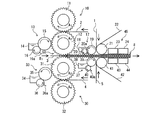
図1及び図2は、本発明の第1実施形態としての複両面段ボール製造装置を説明するための図であって、図1はその側面図、図2はその装置により製造される複両面段ボールシートの側面図である。
Hereinafter, embodiments of the present invention will be described with reference to the drawings.
(A) 1st Embodiment FIG.1 and FIG.2 is a figure for demonstrating the double-sided cardboard manufacturing apparatus as 1st Embodiment of this invention, Comprising: FIG. 1 is the side view, FIG. 2 is the apparatus. It is a side view of the double-sided corrugated board sheet manufactured by this.
図2に示すように、本実施形態にかかる複両面段ボール装置は、裏ライナ(第1のライナ)1、波形に成形された(段繰られた)中芯(第1の中芯)2、中間ライナ3、段繰られた中芯(第2の中芯)4、表ライナ(第2のライナ)5の5層構造を有する複両面段ボールシートを製造するようになっている。具体的には、まず、中間ライナ3の一面に段繰られた中芯2を貼り合わせるとともに、中間ライナ3の他面に段繰られた中芯4を貼り合わせ、その後、中芯2に裏ライナ1を貼り付けるとともに、中芯4に表ライナ5を貼り付けて、複両面段ボールシート8を製造する。
As shown in FIG. 2, the double-sided cardboard apparatus according to the present embodiment includes a back liner (first liner) 1, a corrugated (stepped) core (first core) 2, A double-sided corrugated cardboard sheet having a five-layer structure of an intermediate liner 3, a stepped middle core (second core) 4, and a front liner (second liner) 5 is manufactured. Specifically, first, the
このため、本複両面段ボール製造装置は、図1に示すように、中芯2を段繰る段繰り装置(第1の段繰り装置)10と、段繰り装置10により段繰られた中芯2の一面側の段頂部(又は単に頂部ともいう)に糊を付着させる糊付け装置(第1の糊付け装置)13と、中芯4を段繰る段繰り装置(第2の段繰り装置)30と、段繰り装置30により段繰られた中芯4の一面側の段頂部に糊を付着させる糊付け装置(第2の糊付け装置)33と、糊付け装置13により糊付けされた中芯2を中間ライナ3の一面に貼り合わせると同時に、糊付け装置33により糊付けされた中芯4を中間ライナ3の他面に貼り合わせる中芯貼付け装置50と、中芯貼付け装置50により中間ライナ3に貼り合わせられた中芯2の他面側の段頂部に糊付けする糊付け装置(第3の糊付け装置)17と、中芯貼付け装置50により中間ライナ3に貼り合わせられた中芯4の他面側の段頂部に糊付けする糊付け装置(第4の糊付け装置)37と、中芯2の他面側の段頂部に裏ライナ1を貼り合わせるとともに中芯4の他面側の段頂部に表ライナ5を貼り合わせるダブルフェーサ45とを主に備えて構成されている。
For this reason, as shown in FIG. 1, the present double-sided corrugated board manufacturing apparatus includes a stepping device (first stepping device) 10 for stepping the
段繰り装置10は、上下に互いに対向して配置された一対の上段ロール(第1の段ロール)11及び下段ロール(第2の段ロール)12を備えて構成されている。また、上段ロール11及び下段ロール12は、図示しない駆動装置により直接的又は間接的にそれぞれ逆方向に回転するようになっている。ここでは、上段ロール11は図1中矢印A1方向へ回転し、且つ、下段ロール12は図1中矢印A2方向へ回転するようになっている。
The
段繰り装置10の上段ロール11及び下段ロール12の表面はそれぞれ周方向において波形に形成されており(即ち、図示しないが段山及び段谷が形成されており)、上段ロール11及び下段ロール12が対接するニップ部において、上段ロール11の段山と下段ロール12の段谷とが互いに噛み合うとともに、上段ロール11の段谷と下段ロール12の段山とが互いに噛み合うようになっている。そして、中芯2は、上段ロール11と下段ロール12とのニップ部へ略水平に進入して(挿入されて)波形に段繰られ、その後、下段ロール12の表面に半周巻回されて中芯貼付け装置50に送られる。
The surfaces of the
また、上段ロール11及び下段ロール12の内部には蒸気が封入されており、これにより上段ロール11及び下段ロール12の表面は加熱されている。このように中芯2を加熱することで、中芯2と中間ライナ3とをより確実に貼合できるようになっている。
糊付け装置13は、下段ロール12の中芯2が巻回された領域に近接して設けられている。具体的には、糊付け装置13は、糊を貯めておく糊溜め14と、糊溜め14の糊を下段ロール12に巻回されている中芯2の段頂部(中芯2の一面側の段頂部)に付着させる糊付けロール15と、糊付けロール15表面に付着した糊を必要に応じて掻き取るスクレーパ16aが突設された掻き取りロール16とを備えて構成されている。
Further, steam is sealed inside the
The
一方、段繰り装置30は、段繰り装置10の下方に設けられており、上下に互いに対向して配置された一対の上段ロール(第3の段ロール)31及び下段ロール(第4の段ロール)32を備えて構成されている。即ち、段繰り装置10の上段ロール11及び下段ロール12,段繰り装置30の上段ロール31及び下段ロール32の4つのロールが装置上下方向に並んで配置されている。また、上段ロール31及び下段ロール32は、図示しない駆動装置により直接的又は間接的にそれぞれ逆方向に回転するようになっている。ここでは、上段ロール31は図1中矢印A3方向へ回転し、且つ、下段ロール32は図1中矢印A4方向へ回転するようになっている。なお、段繰り装置10の下段ロール12と段繰り装置30の上段ロール31との回転方向も逆方向となっている。
On the other hand, the
段繰り装置30の上段ロール31及び下段ロール32の表面はそれぞれ周方向において波形に形成されており(即ち、図示しないが段山及び段谷が形成されており)、上段ロール31及び下段ロール32が対接するニップ部において、上段ロール31の段山と下段ロール32の段谷とが互いに噛み合うとともに、上段ロール31の段谷と下段ロール32の段山とが互いに噛み合うようになっている。そして、中芯4は、上段ロール31と下段ロール32とのニップ部へ略水平に進入して(挿入されて)波形に段繰られ、その後、上段ロール31の表面に半周巻回されて中芯貼付け装置50に送られる。
The surfaces of the
また、上段ロール31及び下段ロール32の内部には蒸気が封入されており、これにより上段ロール31及び下段ロール32の表面は加熱されている。このように中芯4を加熱することで、中芯4と中間ライナ3とをより確実に貼合できるようになっている。
糊付け装置33は、上段ロール31の中芯4が巻回された領域に近接して設けられている。具体的には、糊付け装置33は、糊を貯めておく糊溜め34と、糊溜め34の糊を上段ロール31に巻回されている中芯4の段頂部(中芯4の一面側の段頂部)に付着させる糊付けロール35と、糊付けロール35表面に付着した糊を必要に応じて掻き取るスクレーパ36aが突設された掻き取りロール36とを備えて構成されている。
Further, steam is sealed inside the
The gluing
中芯貼付け装置50は、上述した段繰り装置10の下段ロール12と、段繰り装置30の上段ロール31とから構成されている。即ち、段繰り装置10の下段ロール12と段繰り装置30の上段ロール31とが中芯貼付け装置50の構成要素として兼用されている。下段ロール12と上段ロール31とは対向して配置されているが、互いに噛み合って回転するようにはなっていない。つまり、ここでは、下段ロール12表面の頂部と上段ロール31の頂部とが同期して接するように回転するようになっている。そして、中間ライナ3が図1中矢印B1で示すように下段ロール12と上段ロール31との対接部へ略水平に進入すると、中間ライナ3の上面(一面)に中芯2が貼り合わされると同時に、中間ライナ3の下面(他面)に中芯4が貼り合わされる。これにより、中芯2の段頂部と中芯4の段頂部とがずれることなく確実に同調(同期)して中間ライナ3に貼り合わされる。下段ロール12及び上段ロール31の対接部を抜けた中芯2,中間ライナ3,及び中芯4からなる段ボールシート(中間生成物)は略水平に後工程に搬送される。
The
糊付け装置17は、下段ロール12及び上段ロール31の対接部よりもシート搬送方向下流側であってシート搬送路の上方に設けられている。具体的には、糊付け装置17は、糊を貯めておく糊溜め18と、糊溜め18の糊を中芯2の段頂部(中芯2の他面側の段頂部)に付着させる糊付けロール19と、糊付けロール19表面に付着した糊を必要に応じて掻き取るスクレーパ20aが突設された掻き取りロール20とを備えて構成されている。これにより、中芯2の段頂部に糊が付けられるようになっている。
The gluing
また、糊付け装置37は、下段ロール12及び上段ロール31の対接部よりもシート搬送方向下流側であってシート搬送路の下方に設けられている。具体的には、糊付け装置37は、糊を貯めておく糊溜め38と、糊溜め38の糊を中芯4の段頂部(中芯4の他面側の段頂部)に付着させる糊付けロール39と、糊付けロール39表面に付着した糊を必要に応じて掻き取るスクレーパ40aが突設された掻き取りロール40とを備えて構成されている。これにより、中芯4の段頂部に糊が付けられるようになっている。
The gluing
ダブルフェーサ45は、糊付け装置17及び糊付け装置37のシート搬送方向下流側に設けられており、具体的には、シート搬送路の上方にベルト22を介して配置された加圧装置(第1の加圧手段)23及び加圧装置(第2の加圧手段)24と、シート搬送路の下方にベルト42を介して配置された加熱板(第1の加熱手段)43及び加熱板(第2の加熱手段)44とを主に備えて構成されている。なお、ここでは、シート搬送路の上方に加圧装置23,24を配置するとともにシート搬送路の下方に加熱板43,44を配置する構成としているが、シート搬送路の上方に加圧装置(第1の加圧手段)及び加熱板(第1の加熱手段)を1つずつ配置し、シート搬送路の下方にも加圧装置(第2の加圧手段)及び加熱板(第2の加熱手段)を1つずつ配置する構成としてもよい。この場合、例えばシート搬送方向上流側に加圧装置を配置し、下流側に加熱板を配置する。
The
また、ベルト22は、無端状に形成されており、加圧装置23よりもシート搬送方向上流側に設けられたガイドロール21に巻回されているとともに、ベルト42もベルト22と同様に無端状に形成されており、加熱板43よりもシート搬送方向上流側に設けられたガイドロール41に巻回されている。ガイドロール21は中芯2に近接した位置に配置されているとともに、ガイドロール41は中芯4に近接した位置に配置されている。
Further, the
これにより、裏ライナ1がシート搬送路の略垂直上方から送られてきてガイドロール21及びベルト22により中芯2の段頂部に貼り合せられるとともに、表ライナ5がシート搬送路の略垂直下方から送られてきてガイドロール41及びベルト42により中芯4の段頂部に貼り合せられる。そして、加圧装置23,24により加圧された後、加熱板43,44により加熱されることにより、複両面段ボールシート8が製造される。
As a result, the back liner 1 is fed from substantially vertically above the sheet conveying path and is bonded to the step top of the
本発明の第1実施形態としての複両面段ボール製造装置は、上述のごとく構成されているので、段繰り装置10の下段ロール12及び段繰り装置30の上段ロール31の対接部により、中芯2の段頂部と中芯4の段頂部とを確実に同調させることができる。また、従来のように表面が波形に成形されたロール(上段ロールや下段ロールと同じ表面形状をもつロール)に中芯2や中芯4を巻回させて搬送する構成とはなっていないので、通常走行中に中芯2や中芯4の段頂部が潰れてしまうことはない。これにより、中芯2の段頂部と中芯4の段頂部とが同調した複両面段ボールシート8を製造することが可能になり、複両面段ボールシート8の強度をより向上させることができる。
また、装置構成が簡素であり、装置をコンパクトにすることができる。
Since the double-sided corrugated board manufacturing apparatus according to the first embodiment of the present invention is configured as described above, the center core is formed by the contact portions of the
Further, the apparatus configuration is simple, and the apparatus can be made compact.
(B)第2実施形態
図3は、本発明の第2実施形態としての複両面段ボール製造装置を模式的に示す側面図である。なお、第1実施形態で参照した図2も適宜用いて説明する。
図2に示すように、本実施形態にかかる複両面段ボール装置は、第1実施形態と同様に、裏ライナ(第1のライナ)1、波形に成形された(段繰られた)中芯(第1の中芯)2、中間ライナ3、段繰られた中芯(第2の中芯)4、表ライナ(第2のライナ)5の5層構造を有する複両面段ボールシートを製造するようになっている。ただし、本複両面段ボール製造装置では、まず、裏ライナ1に段繰られた中芯2を貼り合わせて片面段ボールシートを形成するとともに、表ライナ5に段繰られた中芯4を貼り合わせて片面段ボールシートを形成し、その後、これら2つの片面段ボールシートの中芯2及び中芯4を中間ライナ3を介して貼り合わせることで、複両面段ボールシート8を製造する。
(B) 2nd Embodiment FIG. 3: is a side view which shows typically the double-sided corrugated board manufacturing apparatus as 2nd Embodiment of this invention. Note that FIG. 2 referred to in the first embodiment will be used as appropriate.
As shown in FIG. 2, the double-sided corrugated cardboard device according to this embodiment includes a back liner (first liner) 1 and a corrugated core that is formed into a corrugated shape (stepped) as in the first embodiment. To produce a double-sided corrugated cardboard sheet having a five-layer structure of a
このため、本複両面段ボール製造装置は、図3に示すように、中芯2を段繰る段繰り装置(第1の段繰り装置)110と、段繰り装置110により段繰られた中芯2の一面側の段頂部(又は単に頂部ともいう)に糊を付着させる糊付け装置(第1の糊付け装置)113と、糊付け装置113により糊付けされた中芯2に裏ライナ1を貼り合わせて片面段ボールシート(第1の片面段ボールシート)6を形成する加圧装置(第1の加圧装置)160と、中芯4を段繰る段繰り装置(第2の段繰り装置)130と、段繰り装置130により段繰られた中芯4の一面側の段頂部に糊を付着させる糊付け装置(第2の糊付け装置)133と、糊付け装置133により糊付けされた中芯4に表ライナ5を貼り合わせて片面段ボールシート(第1の片面段ボールシート)7を形成する加圧装置(第1の加圧装置)170と、片面段ボールシート6の中芯2の他面側の段頂部に糊付けする糊付け装置(第3の糊付け装置)117と、片面段ボールシート7の中芯4の他面側の段頂部に糊付けする糊付け装置(第4の糊付け装置)137と、片面段ボールシート6の中芯2の段頂部と片面段ボールシート7の中芯4の段頂部とを同調させて中間ライナ3を介して貼り合わせるダブルフェーサ145とを主に備えて構成されている。
For this reason, as shown in FIG. 3, the double-sided corrugated board manufacturing apparatus includes a stepping device (first stepping device) 110 for stepping the
段繰り装置110は、上下に互いに対向して配置された一対の上段ロール(第1の段ロール)111及び下段ロール(第2の段ロール)112を備えて構成されている。また、上段ロール111及び下段ロール112は、図示しない駆動装置により直接的又は間接的にそれぞれ逆方向に回転するようになっている。ここでは、上段ロール111は図3中矢印A1方向へ回転し、且つ、下段ロール112は図3中矢印A2方向へ回転するようになっている。
The
段繰り装置110の上段ロール111及び下段ロール112の表面はそれぞれ周方向において波形に形成されており(即ち、図示しないが段山及び段谷が形成されており)、上段ロール111及び下段ロール112が対接するニップ部において、上段ロール111の段山と下段ロール112の段谷とが互いに噛み合うとともに、上段ロール111の段谷と下段ロール112の段山とが互いに噛み合うようになっている。そして、中芯2は、下段ロール112の下方に搬送されてきて下段ロール112に半周巻回された後、上段ロール111と下段ロール112とのニップ部へ進入して(挿入されて)波形に段繰られ、その後、上段ロール111の表面に半周巻回されて加圧装置160とのニップ部に送られる。
The surfaces of the
また、上段ロール111及び下段ロール112の内部には蒸気が封入されており、これにより上段ロール111及び下段ロール112の表面は加熱されている。このように中芯2を加熱することで、中芯2と裏ライナ1とをより確実に貼合できるようになっている。
糊付け装置113は、上段ロール111の中芯2が巻回された領域に近接して設けられている。具体的には、糊付け装置113は、糊を貯めておく糊溜め114と、糊溜め114の糊を上段ロール112に巻回されている中芯2の段頂部(中芯2の一面側の段頂部)に付着させる糊付けロール115と、糊付けロール115表面に付着した糊を必要に応じて掻き取るスクレーパ116aが突設された掻き取りロール116とを備えて構成されている。
Further, steam is sealed inside the
The
加圧装置160は、上段ロール111にそれぞれ対向して設けられたベルトロール161及びストレッチロール162(第1の一対の対向ロール)と、これら2つの対向ロール161,162に巻回された無端状のベルト163とを備えて構成されている。ベルトロール161及びストレッチロール162はともに上段ロール111とは逆方向(図3に示すC1,C2方向)に回転するようになっている。また、ベルト163はベルトロール161及びストレッチロール162とともに図3中矢印D1方向へ回転し、上段ロール111の周方向における所定領域に押し付けられる(巻回される)ようになっている。これにより、裏ライナ1はベルトロール161側から上段ロール111と加圧装置160とのニップ部に進入し、上記の所定領域において中芯2に貼り合わせられて中芯2と裏ライナ1とからなる片面段ボールシート6が形成され、この片面段ボールシート6がストレッチロール162側から出て装置上方へ搬送されるようになっている。
The
一方、段繰り装置130は、段繰り装置110と所定間隔をあけて対向して設けられており、上下に互いに対向して配置された一対の上段ロール(第3の段ロール)131及び下段ロール(第4の段ロール)132を備えて構成されている。即ち、ここでは、段繰り装置110の上段ロール111及び下段ロール112と、段繰り装置130の上段ロール131及び下段ロール132とが図3中左右方向に所定間隔をあけて対向して配置されている。また、上段ロール131及び下段ロール132は、図示しない駆動装置により直接的又は間接的にそれぞれ逆方向に回転するようになっている。ここでは、上段ロール131は図3中矢印A3方向へ回転し、且つ、下段ロール132は図3中矢印A4方向へ回転するようになっている。
On the other hand, the
段繰り装置130の上段ロール131及び下段ロール132の表面はそれぞれ周方向において波形に形成されており(即ち、図示しないが段山及び段谷が形成されており)、上段ロール131及び下段ロール132が対接するニップ部において、上段ロール131の段山と下段ロール132の段谷とが互いに噛み合うとともに、上段ロール131の段谷と下段ロール132の段山とが互いに噛み合うようになっている。そして、中芯4は、下段ロール132の下方に搬送されてきて下段ロール132に半周巻回された後、上段ロール131と下段ロール132とのニップ部へ進入して(挿入されて)波形に段繰られ、その後、上段ロール131の表面に半周巻回されて加圧装置170とのニップ部に送られる。
The surfaces of the
また、上段ロール131及び下段ロール132の内部には蒸気が封入されており、これにより上段ロール131及び下段ロール132の表面は加熱されている。このように中芯4を加熱することで、中芯4と表ライナ5とをより確実に貼合できるようになっている。
糊付け装置133は、上段ロール131の中芯4が巻回された領域に近接して設けられている。具体的には、糊付け装置133は、糊を貯めておく糊溜め134と、糊溜め134の糊を上段ロール131に巻回されている中芯4の段頂部(中芯4の一面側の段頂部)に付着させる糊付けロール135と、糊付けロール135表面に付着した糊を必要に応じて掻き取るスクレーパ136aが突設された掻き取りロール136とを備えて構成されている。
Further, steam is sealed inside the
The
加圧装置170は、上段ロール131にそれぞれ対向して設けられたベルトロール171及びストレッチロール172(第2の一対の対向ロール)と、これら2つの対向ロール171,172に巻回された無端状のベルト173とを備えて構成されている。ベルトロール171及びストレッチロール172はともに上段ロール131とは逆方向(図3に示すC3,C4方向)に回転するようになっている。また、ベルト173はベルトロール171及びストレッチロール172とともに図3中矢印D2方向へ回転し、上段ロール131の周方向における所定領域に押し付けられて(巻回される)ようになっている。これにより、表ライナ5はベルトロール171側から上段ロール131と加圧装置170とのニップ部に進入し、上記の所定領域において中芯4に貼り合わせられて中芯4と表ライナ5とからなる片面段ボールシート7が形成され、この片面段ボールシート7がストレッチロール172側から出て装置上方へ搬送されるようになっている。
The
上記のように形成された片面段ボールシート6及び片面段ボールシート7は、段繰り装置110及び加圧装置160からなるユニットと段繰り装置130及び加圧装置170からなるユニットとの間の空間の上方へ向かって互いに接近するように走行し、その途中で糊付け装置117及び糊付け装置137により糊付けされるようになっている。
糊付け装置117は、段繰り装置110の上段ロール111と加圧装置160とのニップ部よりもシート搬送方向下流側に設けられている。具体的には、糊付け装置117は、糊を貯めておく糊溜め118と、糊溜め118の糊を中芯2の段頂部(中芯2の他面側の段頂部)に付着させる糊付けロール119と、糊付けロール119表面に付着した糊を必要に応じて掻き取るスクレーパ120aが突設された掻き取りロール120とを備えて構成されている。これにより、片面段ボールシート6の中芯2の段頂部に糊が付けられるようになっている。
The single-sided cardboard sheet 6 and the single-sided cardboard sheet 7 formed as described above are located above the space between the unit composed of the
The
また、糊付け装置137は、段繰り装置130の上段ロール131と加圧装置170とのニップ部よりもシート搬送方向下流側に設けられている。具体的には、糊付け装置137は、糊を貯めておく糊溜め138と、糊溜め138の糊を中芯4の段頂部(中芯4の他面側の段頂部)に付着させる糊付けロール139と、糊付けロール139表面に付着した糊を必要に応じて掻き取るスクレーパ140aが突設された掻き取りロール140とを備えて構成されている。これにより、片面段ボールシート7の中芯4の段頂部に糊が付けられるようになっている。
The
ダブルフェーサ145は、糊付け装置117及び糊付け装置137よりもシート搬送方向下流側(装置上方)に設けられており、具体的には、シート搬送路の図3中左側にベルト122を介して配置された加圧装置123,124と、シート搬送路の下方にベルト142を介して配置された加熱板143,144とを主に備えて構成されている。
また、ベルト122は、無端状に形成されており、加圧装置123よりもシート搬送方向上流側(装置下方)に設けられたガイドロール121に巻回されているとともに、ベルト142もベルト122と同様に無端状に形成されており、加熱板143よりもシート搬送方向上流側(装置下方)に設けられたガイドロール141に巻回されている。
The
Further, the
これにより、中間ライナ3が、図3中矢印F1で示すように、段繰り装置110及び加圧装置160からなるユニットと段繰り装置130及び加圧装置170からなるユニットとの間の空間の下方から上方へ搬送されてきて、ガイドロール121及びガイドロール141間に進入し、一面側に片面段ボールシート6の中芯2の段頂部が貼り付けられるとともに、他面側に片面段ボールシート7の中芯4の段頂部が貼り付けられる。そして、加圧装置123,124により加圧された後、加熱板143,144により加熱されることにより、複両面段ボールシート8が製造される。
As a result, as shown by the arrow F 1 in FIG. 3, the intermediate liner 3 has a space between the unit made up of the
また、本複両面段ボール製造装置には、ベルトロール161及びベルトロール171の回転速度を調整する調整装置180が設けられており、この調整装置180により、ベルトロール161及びベルトロール171の回転速度を調整することで片面段ボールシート6及び片面段ボールシート7の速度を調整して、片面段ボールシート6の中芯2の段頂部と片面段ボールシート7の中芯4の段頂部とを同調させて中間ライナ3に貼り合わせることができるようになっている。なお、ここでは、ベルトロール161及びベルトロール171の両方の回転速度を調整するようにしているが、一方の回転速度のみを調整するようにしてもよい。また、ベルトロール161及びベルトロール171の代わりに、上段ロール111及び上段ロール131の一方又は両方の回転速度を調整するようにしてもよい。あるいは、図示はしないが、例えば紙継ぎ装置において予め裏ライナ1及び表ライナ5にかかる張力を調整することにより、片面段ボールシート6の中芯2の段頂部と片面段ボールシート7の中芯4の段頂部とを同調させるようにしてもよい。
Further, the present double-sided corrugated board manufacturing apparatus is provided with an
本発明の第2実施形態としての複両面段ボール製造装置は、上述のごとく構成されているので、中芯2の段頂部と中芯4の段頂部とを同調させることができるとともに、従来のように表面が波形に成形されたロール(上段ロールや下段ロールと同じ表面形状をもつロール)に中芯2や中芯4を巻回させて搬送する構成とはなっていないので、通常走行中に中芯2や中芯4の段頂部が潰れてしまうことがない。これにより、中芯2の段頂部と中芯4の段頂部とが同調した複両面段ボールシート8を製造することが可能になり、複両面段ボールシート8の強度をより向上させることができる。
Since the double-sided corrugated board manufacturing apparatus according to the second embodiment of the present invention is configured as described above, the step top of the
また、ベルト163を段繰り装置110の上段ロール111の所定領域に巻回させて中芯2に裏ライナ1を押し付けるので面で圧力を付与することができる。これと同様に、ベルト173を段繰り装置130の上段ロール131の所定領域に巻回させて中芯4に表ライナ5を押し付けるので面で圧力を付与することができる。これにより、線圧を付与して押し付けたときよりも、装置振動を減少させることができるとともに、プレスマークを減少させて高品質な製品を製造することができる。
さらに、装置構成が簡素であり、装置をコンパクトにすることができる。
Further, since the
Furthermore, the apparatus configuration is simple and the apparatus can be made compact.
(C)第3実施形態
図4は、本発明の第3実施形態としての複両面段ボール製造装置を模式的に示す側面図である。なお、図4において、前述した第2実施形態の複両面段ボール製造装置と同一の部位については同一の符号を用いて示し、その詳細な説明は第2実施形態と同様であるので省略する。
(C) Third Embodiment FIG. 4 is a side view schematically showing a double-sided cardboard manufacturing apparatus as a third embodiment of the present invention. In FIG. 4, the same parts as those in the double-sided corrugated board manufacturing apparatus of the second embodiment described above are denoted by the same reference numerals, and detailed description thereof is omitted because it is the same as that of the second embodiment.
図4に示すように、本実施形態にかかる複両面段ボール製造装置は、上述した第2実施形態とは、加圧装置160及び加圧装置170の構成が異なる。すなわち、本実施形態では、加圧装置160は、段繰り装置110の上段ロール111の上方に対向して配置され上段ロール111に接触して回転しうる加圧ロール(第1の加圧ロール)160aをそなえて構成されているとともに、加圧装置170は、段繰り装置130の上段ロール131の上方に対向して配置され上段ロール131に接触して回転しうる加圧ロール(第2の加圧ロール)170aをそなえて構成されている。また、加圧ロール160aは上段ロール111とは逆方向(図4に示すE1方向)に回転し、加圧ロール170aは上段ロール131とは逆方向(図4に示すE2方向)に回転するようになっている。
As shown in FIG. 4, the double-sided corrugated board manufacturing apparatus according to the present embodiment is different from the second embodiment described above in the configuration of the
また、この場合、調整装置180により、加圧ロール160a及び加圧ロール170aの回転速度が調整されるようになっており、これにより、片面段ボールシート6及び片面段ボールシート7の速度を調整して、片面段ボールシート6の中芯2の段頂部と片面段ボールシート7の中芯4の段頂部とを同調させて中間ライナ3に貼り合わせることができるようになっている。なお、ここでは、加圧ロール160a及び加圧ロール170aの両方の回転速度を調整するようにしているが、一方の回転速度のみを調整するようにしてもよい。また、加圧ロール160a及び加圧ロール170aの代わりに、上段ロール111及び上段ロール131の一方又は両方の回転速度を調整するようにしてもよい。あるいは、図示はしないが、例えば紙継ぎ装置において予め裏ライナ1及び表ライナ5にかかる張力を調整することにより、片面段ボールシート6の中芯2の段頂部と片面段ボールシート7の中芯4の段頂部とを同調させるようにしてもよい。
In this case, the adjusting
このような構成によっても、上述した第2実施形態と同様に、中芯2の段頂部と中芯4の段頂部とを同調させることができるとともに、従来のように表面が波形に成形されたロール(上段ロールや下段ロールと同じ表面形状をもつロール)に中芯2や中芯4を巻回させて搬送する構成とはなっていないので、通常走行中に中芯2や中芯4の段頂部が潰れてしまうことがない。これにより、中芯2の段頂部と中芯4の段頂部とが同調した複両面段ボールシート8を製造することが可能になり、複両面段ボールシート8の強度をより向上させることができる。
Even with such a configuration, the step top of the
(D)その他
以上、本発明の実施形態について説明したが、本発明は上記の実施形態に限定されるものではなく、本発明の趣旨を逸脱しない範囲で種々変形して実施することができる。例えば、上述した実施形態の糊付け装置の構成はこれに限定されない。
また、第1実施形態において、中芯2を上段ロール11に半周巻回させた後、上段ロール11と下段ロール12とのニップ部へ進入させるようにしてもよい。これと同様に、中芯4を下段ロール32に半周巻回させた後、上段ロール31と下段ロール32とのニップ部へ進入させるようにしてもよい。
(D) Others Although the embodiment of the present invention has been described above, the present invention is not limited to the above embodiment, and various modifications can be made without departing from the spirit of the present invention. For example, the configuration of the gluing device of the above-described embodiment is not limited to this.
In the first embodiment, the
さらに、第2,3実施形態において、中芯2を上段ロール111と下段ロール112とのニップ部へ略水平に直接進入させたり、中芯4を上段ロール131と下段ロール132とのニップ部へ略水平に直接進入させたりしてもよい。
Further, in the second and third embodiments, the
1 裏ライナ(第1のライナ)
2 中芯(第1の中芯)
3 中間ライナ
4 中芯(第2の中芯)
5 表ライナ(第2のライナ)
6 片面段ボールシート(第1の片面段ボールシート)
7 片面段ボールシート(第2の片面段ボールシート)
8 複両面段ボールシート
10,30,110,130 段繰り装置
11,31,111,131 上段ロール
12,32,112,132 下段ロール
13,17,33,37,113,117,133,137 糊付け装置
14,18,34,38,114,118,134,138 糊溜め
15,19,35,39,115,119,135,139 糊付けロール
16,20,36,40,116,120,136,140 掻き取りロール
21,41,121,141 ガイドロール
22,42,122,142 ベルト
23,24,123,124 加圧装置
43,44,143,144 加熱板
45,145 ダブルフェーサ
50 中芯貼付け装置
160,170 加圧装置
160a,170a 加圧ロール
161,171 ベルトロール
162,172 ストレッチロール
180 調整装置
1 Back liner (first liner)
2 center core (first core)
3 Intermediate liner 4 Center core (second core)
5 Front liner (second liner)
6 single-sided cardboard sheet (first single-sided cardboard sheet)
7 single-sided cardboard sheet (second single-sided cardboard sheet)
8 Double-sided
Claims (9)
互いに噛み合い該第1の中芯を段繰る第1及び第2の段ロールと、
互いに噛み合い該第2の中芯を段繰る第3及び第4の段ロールとをそなえ、
該第2の段ロールと該第3の段ロールとが互いに波形表面の頂部を同調させて回転し、段繰られて該第2の段ロールに巻回された該第1の中芯と、段繰られて該第3の段ロールに巻回された該第2の中芯との間に該中間ライナを挟んで、該第1の中芯及び該第2の中芯の各段頂部を該中間ライナに押し付けて貼り合わせるように構成された
ことを特徴とする、複両面段ボール製造装置。 A double-sided cardboard for producing a double-sided cardboard sheet having a five-layer structure by joining a first liner, a first core, an intermediate liner, a second core, and a second liner in this order. Manufacturing equipment,
First and second corrugating rolls that mesh with each other and roll the first core;
Comprising third and fourth corrugating rolls that mesh with each other and roll the second core;
The second corrugated roll and the third corrugated roll rotate in synchronism with the top of the corrugated surface, and the first core wound and wound around the second corrugated roll; The intermediate liner is sandwiched between the second core and the second core wound around the third corrugated roll, and the top portions of the first core and the second core are A double-sided corrugated board manufacturing apparatus characterized by being configured to be pressed against and bonded to the intermediate liner.
ことを特徴とする、請求項1記載の複両面段ボール製造装置。 2. The double-sided corrugated board manufacturing apparatus according to claim 1, wherein the first, second, third and fourth corrugated rolls are arranged side by side in the vertical direction of the apparatus.
ことを特徴とする、請求項1又は2記載の複両面段ボール製造装置。 A first guide roll that presses and bonds the first liner to a surface on the first core side of a sheet formed from the first core, the second core, and the intermediate liner; The double-sided corrugated board manufacturing apparatus according to claim 1 or 2, further comprising a second guide roll that presses and bonds the second liner to a surface on the second core side.
互いに噛み合い該第1の中芯を段繰る第1及び第2の段ロールと、
互いに噛み合い該第2の中芯を段繰る第3及び第4の段ロールと、
段繰られて該第1の段ロールの表面に巻回された状態の該第1の中芯に該第1のライナを押し付けて貼り合わせる第1の加圧装置と、
段繰られて該第3の段ロールの表面に巻回された状態の該第2の中芯に該第2のライナを押し付けて貼り合わせる第2の加圧装置と、
該第1のライナが貼り合わされた該第1の中芯と該第2のライナが貼り合わされた該第2の中芯との各段頂部を同調させるとともに間に該中間ライナを挟んで、該第1の中芯及び該第2の中芯の各段頂部を該中間ライナに押し付けて貼り合わせる第1及び第2のガイドロールとをそなえている
ことを特徴とする、複両面段ボール製造装置。 A double-sided cardboard for producing a double-sided cardboard sheet having a five-layer structure by joining a first liner, a first core, an intermediate liner, a second core, and a second liner in this order. Manufacturing equipment,
First and second corrugating rolls that mesh with each other and roll the first core;
Third and fourth corrugating rolls that mesh with each other and roll the second core;
A first pressure device that presses and bonds the first liner to the first core in a state of being wound around the surface of the first corrugated roll;
A second pressure device that presses and bonds the second liner to the second core in a state of being wound around the surface of the third corrugated roll;
Synchronizing the tops of the first core to which the first liner is bonded and the second core to which the second liner is bonded, and sandwiching the intermediate liner therebetween, An apparatus for producing double-sided corrugated cardboard, comprising: first and second guide rolls that press and bond each of the first core and the top of the second core to the intermediate liner.
該第1の段ロールに対向して配置された第1の一対の対向ロールと、
該第1の一対の対向ロールに巻回され、該第1の段ロールの表面に接触する無端状のベルトとをそなえて構成されているとともに、
該第2の加圧装置が、
該第3の段ロールに対向して配置された第2の一対の対向ロールと、
該第2の一対の対向ロールに巻回され、該第3の段ロールの表面に接触する無端状のベルトとをそなえて構成されている
ことを特徴とする、請求項4記載の複両面段ボール製造装置。 The first pressurizing device comprises:
A first pair of opposed rolls disposed to face the first corrugated roll;
The endless belt is wound around the first pair of opposed rolls and is in contact with the surface of the first corrugated roll.
The second pressurizing device comprises:
A second pair of opposing rolls disposed opposite the third corrugated roll;
The double-sided corrugated cardboard according to claim 4, further comprising an endless belt wound around the second pair of opposed rolls and contacting the surface of the third corrugated roll. Manufacturing equipment.
ことを特徴とする、請求項5記載の複両面段ボール製造装置。 6. An adjusting device is provided for adjusting one rotational speed of the first pair of opposed rolls and one rotational speed of the second pair of opposed rolls. The double-sided cardboard manufacturing apparatus described.
該第2の加圧装置が、該第3の段ロールに対向して配置され該第3の段ロールに接触する第2の加圧ロールをそなえて構成されている
ことを特徴とする、請求項4記載の複両面段ボール製造装置。 The first pressure device is configured to include a first pressure roll disposed opposite to the first corrugated roll and in contact with the first corrugated roll,
The second pressurizing device includes a second pressurizing roll that is disposed to face the third corrugated roll and is in contact with the third corrugated roll. Item 5. The double-sided cardboard manufacturing apparatus according to Item 4.
該複両面段ボールシートの他面を加圧する第2の加圧手段と加熱する第2の加熱手段とをそなえている
ことを特徴とする、請求項1〜7の何れか1項に記載の複両面段ボール製造装置。 A first pressing means for pressing one side of the double-sided cardboard sheet and a first heating means for heating;
The double-sided cardboard sheet according to any one of claims 1 to 7, further comprising a second pressure unit that pressurizes the other surface of the double-sided cardboard sheet and a second heating unit that heats the double-sided cardboard sheet. Double-sided cardboard manufacturing equipment.
該複両面段ボールシートの他面を加熱する複数の加熱手段とをそなえている
ことを特徴とする、請求項1〜7の何れか1項に記載の複両面段ボール製造装置。 A plurality of pressing means for pressing one surface of the double-sided cardboard sheet;
The double-sided cardboard manufacturing apparatus according to any one of claims 1 to 7, further comprising a plurality of heating means for heating the other surface of the double-sided cardboard sheet.
Priority Applications (1)
| Application Number | Priority Date | Filing Date | Title |
|---|---|---|---|
| JP2004288014A JP2006096009A (en) | 2004-09-30 | 2004-09-30 | Device for manufacturing plural double-faced corrugated fiberboard |
Applications Claiming Priority (1)
| Application Number | Priority Date | Filing Date | Title |
|---|---|---|---|
| JP2004288014A JP2006096009A (en) | 2004-09-30 | 2004-09-30 | Device for manufacturing plural double-faced corrugated fiberboard |
Publications (1)
| Publication Number | Publication Date |
|---|---|
| JP2006096009A true JP2006096009A (en) | 2006-04-13 |
Family
ID=36236279
Family Applications (1)
| Application Number | Title | Priority Date | Filing Date |
|---|---|---|---|
| JP2004288014A Withdrawn JP2006096009A (en) | 2004-09-30 | 2004-09-30 | Device for manufacturing plural double-faced corrugated fiberboard |
Country Status (1)
| Country | Link |
|---|---|
| JP (1) | JP2006096009A (en) |
Cited By (4)
| Publication number | Priority date | Publication date | Assignee | Title |
|---|---|---|---|---|
| SG161155A1 (en) * | 2008-11-03 | 2010-05-27 | Master Pack Sdn Bhd | Quadruple-wall corrugated paperboard and method of manufacture |
| JP2013049275A (en) * | 2012-10-11 | 2013-03-14 | Toppan Printing Co Ltd | Method and apparatus for manufacturing corrugated cardboard |
| JP2013538134A (en) * | 2010-07-07 | 2013-10-10 | ビージェイツー,エルエルシー | Apparatus and method for making corrugated products |
| US8652613B2 (en) | 2010-02-09 | 2014-02-18 | Master-Pack Sdn. Bhn. | Quadruple-wall corrugated paperboard and method of manufacture |
-
2004
- 2004-09-30 JP JP2004288014A patent/JP2006096009A/en not_active Withdrawn
Cited By (7)
| Publication number | Priority date | Publication date | Assignee | Title |
|---|---|---|---|---|
| SG161155A1 (en) * | 2008-11-03 | 2010-05-27 | Master Pack Sdn Bhd | Quadruple-wall corrugated paperboard and method of manufacture |
| US8652613B2 (en) | 2010-02-09 | 2014-02-18 | Master-Pack Sdn. Bhn. | Quadruple-wall corrugated paperboard and method of manufacture |
| JP2013538134A (en) * | 2010-07-07 | 2013-10-10 | ビージェイツー,エルエルシー | Apparatus and method for making corrugated products |
| JP2016164001A (en) * | 2010-07-07 | 2016-09-08 | ビージェイツー,エルエルシー | Device and method for manufacturing waveform processing product |
| US10035299B2 (en) | 2010-07-07 | 2018-07-31 | Bj2, Llc | Apparatus and method for making a corrugated product |
| KR101901562B1 (en) * | 2010-07-07 | 2018-09-27 | 비제이투, 엘엘씨 | Apparatus and method for making a corrugated product |
| JP2013049275A (en) * | 2012-10-11 | 2013-03-14 | Toppan Printing Co Ltd | Method and apparatus for manufacturing corrugated cardboard |
Similar Documents
| Publication | Publication Date | Title |
|---|---|---|
| JPH01196334A (en) | Method and device for manufacturing corrugated board product | |
| KR20150027220A (en) | Improvements in and relating to paperboard manufacture | |
| JPH04221626A (en) | Manufacturing machine for single-faced corrugated board | |
| US20120193026A1 (en) | Device for producing corrugated cardboard and related method | |
| JPH1058563A (en) | Device for manufacturing corrugated board sheet | |
| AU697768B1 (en) | Single-faced corrugated fiberboard sheet manufacturing apparatus | |
| CA1304663C (en) | Manufacturing corrugated board | |
| JP2006096009A (en) | Device for manufacturing plural double-faced corrugated fiberboard | |
| JP6077535B2 (en) | Paper web material manufacturing apparatus and manufacturing method | |
| JP2003291230A (en) | Apparatus for laminating double-faced corrugated cardboard sheet | |
| JP5199586B2 (en) | Heating control method for steam heating corrugated roll of corrugated board manufacturing apparatus | |
| JP3626474B2 (en) | Corrugated paper | |
| JP3477331B2 (en) | Laminated sheet material manufacturing system with warpage prevention device | |
| JP2017030327A (en) | Double corrugated cardboard sheet and method of manufacturing the same | |
| JPH07285186A (en) | Single facer | |
| JP2000062054A (en) | Manufacturing machine of double wall corrugated fiberboard | |
| JP2004168026A (en) | Corrugating medium for corrugated cardboard, corrugated cardboard sheet, and devices for producing the corrugating medium and the corrugated cardboard sheet | |
| JP2009196332A (en) | Single facer and method of forming corrugating medium | |
| JPH11147268A (en) | Single-faced corrugated cardboard producing apparatus | |
| JPS6024582Y2 (en) | Corrugated cardboard manufacturing equipment | |
| JP4405985B2 (en) | Manufacturing method of polyimide double-sided metal foil laminate | |
| JP2006035643A (en) | Corrugated paper and manufacturing method of corrugated paper | |
| JP2003334873A (en) | Slip sheet device for wales and course composite double- faced corrugated cardboard | |
| JPH047942Y2 (en) | ||
| TW201404584A (en) | Improvements in and relating to paperboard manufacture |
Legal Events
| Date | Code | Title | Description |
|---|---|---|---|
| A300 | Withdrawal of application because of no request for examination |
Free format text: JAPANESE INTERMEDIATE CODE: A300 Effective date: 20071204 |