JP2006095628A - Twist drill - Google Patents
Twist drill Download PDFInfo
- Publication number
- JP2006095628A JP2006095628A JP2004283251A JP2004283251A JP2006095628A JP 2006095628 A JP2006095628 A JP 2006095628A JP 2004283251 A JP2004283251 A JP 2004283251A JP 2004283251 A JP2004283251 A JP 2004283251A JP 2006095628 A JP2006095628 A JP 2006095628A
- Authority
- JP
- Japan
- Prior art keywords
- cutting edge
- drill
- tool
- chip discharge
- cutting
- Prior art date
- Legal status (The legal status is an assumption and is not a legal conclusion. Google has not performed a legal analysis and makes no representation as to the accuracy of the status listed.)
- Pending
Links
Images

Abstract
Description
本願発明は、ツイストドリルにおいて切削中の工具挙動が安定性するドリルに関する。 The present invention relates to a drill having stable tool behavior during cutting in a twist drill.
ドリルで穴加工を行う場合、刃先で生成された切り屑がドリル溝面と加工壁面に囲まれた空間を通り排出されるので切り屑の処理性が問題になる。また、工具剛性の弱さや、切刃のドリル中心からの距離による切削速度の変化、特に中心部では切削速度が0で押しつぶし加工になるために大きな切削抵抗が発生し、切削中の工具挙動が不安定となる。従来の直線状の切れ刃は切刃側溝底に内接する略円弧の曲率が大きいため切り屑を処理性の良い形状にカールさせる効果に乏しく、切り屑処理性の付与だけでは切削中の工具挙動を安定させるには十分とはいえない。更に、切刃側のみにマージンを設けた場合は工具挙動を安定させることが不十分であった。このような例として、特許文献1、2がある。
When drilling with a drill, chips generated at the cutting edge are discharged through the space surrounded by the drill groove surface and the processing wall surface, so chip disposal becomes a problem. Also, changes in cutting speed due to weak tool rigidity and the distance of the cutting edge from the drill center, especially at the center, the cutting speed is 0 and the crushing process causes a large cutting resistance. It becomes unstable. The conventional linear cutting edge has a large curvature of a substantially arc inscribed in the groove bottom groove, so the effect of curling the chip into a shape with good processability is poor. It is not enough to stabilize. Furthermore, when a margin is provided only on the cutting edge side, it is insufficient to stabilize the tool behavior. As such examples, there are
本願発明は、切削中の工具挙動を安定させるため、凹状切刃とすることで直線状切刃と比較し、切刃に切り屑の処理性を付与するとともに切り屑排出溝の面積を大きくし、更に、ヒール側にマージンを設けることで切削中の工具挙動を安定させることで、このような問題を解決した工具を提供する。 In order to stabilize the tool behavior during cutting, the present invention provides a cutting edge to the cutting edge and increases the area of the chip discharge groove as compared with a linear cutting edge by using a concave cutting edge. Furthermore, by providing a margin on the heel side, the tool behavior during cutting is stabilized, thereby providing a tool that solves such a problem.
本願発明は、軸線回りに回転される工具本体の先端部外周に、一対の切屑排出溝が上記軸線を挟んで互いに反対側に設けられるとともに、これらの切屑排出溝の回転方向を向く壁面の先端には切刃が設けられてなる穴明け工具であって、心厚をW、軸直角断面における切刃側溝底に内接する略円弧の曲率をR1とするとき、R1=(1.3〜2.0)Wの範囲で構成される凹状切刃を有し、該穴明け工具の軸直角断面視でランド部と切り屑排出溝のつながるヒール側にもう一対のマージンを設けたことを特長とするドリルであり、切れ刃を凹状とすることで切刃に切り屑処理性のよい形状にカールさせる効果を付与し、切り屑排出溝の面積を大きくし切り屑排出性を向上した。 According to the present invention, a pair of chip discharge grooves are provided on the outer periphery of the tip of the tool body rotated about an axis on opposite sides of the axis, and the tips of the wall surfaces facing the rotation direction of these chip discharge grooves Is a drilling tool provided with a cutting edge, where R1 = (1.3-2), where W is the thickness of the core, and R1 is the curvature of a substantially arc inscribed in the cutting edge side groove bottom in the cross section perpendicular to the axis. 0.0) W has a concave cutting edge configured in the range of W, and another pair of margins is provided on the heel side where the land portion and the chip discharge groove are connected in a cross-sectional view perpendicular to the axis of the drilling tool, The drill has a concave cutting edge, which gives the cutting blade the effect of curling it into a shape with good chip disposability, increasing the area of the chip discharge groove and improving the chip discharge.
本願発明により、切り屑の処理性が改善され、ヒール側マージンのガイドにより、切削中の工具挙動が安定し、穴加工の安定性を高めたドリルを提供することができた。 According to the present invention, it is possible to provide a drill in which the chip processing property is improved and the tool behavior during cutting is stabilized by the guide on the heel side margin, and the stability of drilling is enhanced.
ドリルで穴加工を行う場合、切り屑処理性の問題、剛性の弱さ、中心部での切削速度が0となるため押しつぶしの加工となり大きな切削抵抗が発生し、切削中の工具挙動が不安定となる。本願発明では、ドリル先端視において切刃形状を凹状として、切刃側溝底に内接する略円弧の曲率を小さくして切り屑の処理性を付与し、切り屑排出溝の面積を大きくするとともに、軸直角断面視でランド部と切削排出溝のつながるヒール側にもう一対のマージンを設け穴壁とのガイド部を設けた。R1がWの1.3倍より小さい場合、切り屑排出溝容積を十分に確保することができないため切刃側の溝底部で切り屑が詰まる傾向となり排出性が阻害される。R1がWの2.0倍より大きい場合切り屑をカールさせる効果に乏しくなり切り屑のカール半径が大きくなり溝内に切り屑が詰まる傾向となるため、R1=(1.3〜2.0)Wの範囲とした。
軸直角断面視でランド部と切削排出溝のつながるヒール側にもう一対のマージンを設けマージン巾を規定することで、穴壁で工具を支えるガイド部を増やして穴壁でドリルを支持することで切削抵抗の増加を防ぎ、切削中の工具挙動を安定させることができた。
ヒール側のマージンを設ける位置は、切刃コーナーよりヒール側に向かって75°より切刃コーナーに近い位置や、105°より遠い位置ではガイドの効果が小さくなるため75°〜105°の範囲とした。
ヒール側のマージン巾はドリル直径の3.0%より狭い場合十分なガイド効果を得ることができず、6.5%より広い場合穴壁との接触面積が増大し抵抗が大きくなりドリルの挙動が不安定となるため、3.0%〜6.5%の範囲とした。
該ドリルにクーラントホールを設けてクーラントとして油性切削油、水溶性切削油、ミスト及びエアー等を送ることにより、切削によって生ずる熱の冷却と、潤滑性を高め切屑の排出をよりスムーズに行うことが出来る。
ハイス基材或いは超硬基材の表面に硬質皮膜及び潤滑性膜を、スパッタリング法、プラズマ化学蒸着法、イオン誘導型アーク放電式イオンプレーティング法の何れかもしくはその組合せにより被覆することで、切削寿命、切削作業速度の向上は図れるが、コーティングを施さないものにおいても切削寿命、切削作業速度の低下以外は、切削性能は変わらないものである。
When drilling with a drill, there is a problem with chip disposal, weak rigidity, and the cutting speed at the center is 0, which results in crushing and large cutting resistance, resulting in unstable tool behavior during cutting. It becomes. In the present invention, the cutting edge shape is concave in the drill tip view, the curvature of the substantially arc inscribed in the cutting edge side groove bottom is reduced to give chip processing performance, and the area of the chip discharge groove is increased, Another pair of margins were provided on the heel side where the land portion and the cutting discharge groove were connected in a cross-sectional view perpendicular to the axis, and a guide portion with the hole wall was provided. When R1 is smaller than 1.3 times W, the chip discharge groove volume cannot be secured sufficiently, and the chip tends to be clogged at the groove bottom on the cutting edge side, and the discharge performance is hindered. When R1 is larger than 2.0 times W, the effect of curling the chips becomes poor, the curl radius of the chips becomes large, and the chips tend to be clogged in the groove. Therefore, R1 = (1.3 to 2.0 ) W range.
By providing another pair of margins on the heel side where the land and cutting discharge groove are connected in a cross-sectional view perpendicular to the axis and defining the margin width, the guide wall supporting the tool on the hole wall is increased and the drill is supported on the hole wall. The increase in cutting resistance was prevented, and the tool behavior during cutting was stabilized.
The position where the margin on the heel side is provided is in the range of 75 ° to 105 ° because the effect of the guide is reduced at a position closer to the cutting edge corner than 75 ° from the cutting edge corner toward the heel side, or at a position farther than 105 °. did.
If the margin width on the heel side is narrower than 3.0% of the drill diameter, a sufficient guide effect cannot be obtained. If the margin width is larger than 6.5%, the contact area with the hole wall increases and the resistance increases and the behavior of the drill increases. Is unstable, so the range was 3.0% to 6.5%.
By providing a coolant hole in the drill and sending oil-based cutting oil, water-soluble cutting oil, mist, air, etc. as coolant, it is possible to cool the heat generated by cutting and improve lubricity and discharge chips more smoothly. I can do it.
By coating the surface of a high-speed substrate or carbide substrate with a hard film and a lubricating film by sputtering method, plasma chemical vapor deposition method, ion induction type arc discharge ion plating method or a combination thereof, cutting is performed. Although the life and cutting work speed can be improved, the cutting performance is not changed except for the reduction of the cutting life and cutting work speed even when the coating is not applied.
(実施例1)
超硬ドリルの形状を、ドリル径=6.0mm、溝長=45mm、全長=100mm、捩れ角=30°、ヒール側マージンの位置を90°、クーラントホール付き、を用いて、切刃側溝底に内接する略円弧の曲率R1を、比較例1、1.2W、本発明例2、同1.3W、本発明例3、同1.6W、本発明例4、同2.0W、比較例5、同2.1W、の5試料コーティング超硬ドリルを製作した。コーティングはTiAlNをイオン誘導型アーク放電式イオンプレーティング法とスパッタリング法を組み合わせて施した。
上記各3本を、切削速度=100m/min、1回転送り=0.15mm/rev、被削材は一般の機械部品等に使用される一般鋼や合金鋼等のうちS50C(220〜280HB)、クーラントホールを通して水溶性切削液を供給、穴深さ18mmの貫通穴を加工する条件で、BT40番の縦型マシニングセンターで10穴の加工を行い、切削状況を確認した。結果、機械主軸負荷が比較例1はR1が小さいため切り屑が詰まる傾向に成り5〜15%、本発明例1は4〜6%、本発明例2は1〜2%、本発明例3は3〜5%、比較例2はR1が大きいため切り屑をカールさせる効果が小さく処理性が悪いため切り屑が詰まる傾向になり5〜12%の変動幅となった。
Example 1
Carbide drill shape, drill diameter = 6.0mm, groove length = 45mm, total length = 100mm, twist angle = 30 °, heel side margin position 90 °, with coolant hole, cutting edge side groove bottom The curvature R1 of the substantially arc inscribed in the following is Comparative Example 1, 1.2W, Invention Example 2, 1.3W, Invention Example 3, 1.6W, Invention Example 4, 2.0W, Comparative Example 5 and 2.1 W, 5 sample coated carbide drills were manufactured. The coating was performed by combining TiAlN with an ion induction arc discharge ion plating method and a sputtering method.
Three of each of the above, cutting speed = 100 m / min, 1 rotation feed = 0.15 mm / rev, work material is S50C (220 to 280HB) among general steel and alloy steel used for general machine parts and the like Under the conditions of supplying a water-soluble cutting fluid through the coolant hole and machining a through hole with a hole depth of 18 mm, 10 holes were machined in a vertical machining center of BT40, and the cutting situation was confirmed. As a result, the mechanical spindle load in Comparative Example 1 tends to be clogged because R1 is small, 5 to 15%, Invention Example 1 is 4 to 6%, Invention Example 2 is 1 to 2%, Invention Example 3 3 to 5%, and Comparative Example 2 has a large R1, so the effect of curling the chips is small and the processability is poor, so the chips tend to become clogged, and the fluctuation range is 5 to 12%.
(実施例2)
本発明例3の形状でさらに、マージンの位置を、工具中心を通り両切刃コーナーを結んだ直線に対し、切刃コーナーよりヒール側に向かって、比較例6、72°、本発明例7、75°、本発明例8、80°、本発明例9、90°、本発明例10、100°、本発明例11、105°、比較例12、107°の位置に設けたものと、比較例13として切刃側のみにマージンを設けたものに、スパッタリング法によりTiAlNコーティングを施したクーラントホール付き超硬ドリルを製作した。上記各試料3本を、被削材をSCM440(HB280〜330)、その他の切削諸元は実施例1と同じ諸元で穴加工を行い、500穴加工時の刃先を確認した。その結果、比較例6は3本中2本に微小なチッピング、本発明例7〜11は正常摩耗、比較例12は3本中1本に微小なチッピング、比較例13は3本中2本に微小なチッピングを観察した。更に、ドリル表面を観察したところ、コーティング表面が平滑で切り屑処理性が良好であり、併せて切り屑が金属光沢を有し、焼け色がなかった。
(Example 2)
In the shape of Example 3 of the present invention, the margin position is set to Comparative Example 6, 72 ° from the edge of the cutting edge toward the heel side with respect to the straight line passing through the center of the tool and connecting the cutting edge corners, and Example 7 of the invention. , 75 °, Invention Example 8, 80 °, Invention Example 9, 90 °, Invention Example 10, 100 °, Invention Example 11, 105 °, Comparative Example 12, 107 °, As a comparative example 13, a carbide drill with a coolant hole in which a margin was provided only on the cutting edge side and TiAlN coating was applied by a sputtering method was manufactured. The above three samples were subjected to hole machining with SCM440 (HB280-330) as the work material and the same other specifications as in Example 1, and the cutting edge at the time of 500 hole machining was confirmed. As a result, Comparative Example 6 has a minute chipping in two of three, Invention Examples 7 to 11 have normal wear, Comparative Example 12 has a minute chipping in one of three, and Comparative Example 13 has two of three. Minute chipping was observed. Furthermore, when the drill surface was observed, the coating surface was smooth and the chip disposal was good, and the chips had a metallic luster and there was no burnt color.
(実施例3)
本発明例3及び9の形状で、マージンの巾を工具直径の、比較例14、2.7%、本発明例15、3.0%、本発明例16、4.0%、本発明例17、6.0%、本発明例18、6.5%、比較例19、6.8%とし、プラズマ化学蒸着法によりTiAlNコーティングを施した超硬ドリルを製作した。上記各試料3本を、被削材をSS400(HB180〜220)、その他の切削諸元は実施例1と同じ諸元で穴加工を行い、1000穴加工時の刃先を観察した。その結果、比較例14は3本中1本に微小なチッピングを、本発明例15〜18は正常摩耗、比較例19は3本中1本に微小なチッピングが観察された。
(Example 3)
Comparative Examples 14, 2.7%, Invention Examples 15, 3.0%, Invention Examples 16, 4.0%, Invention Examples with the shapes of Invention Examples 3 and 9 and the margin width of the tool diameter. Carbide drills with TiAlN coating were produced by plasma chemical vapor deposition using 17, 6.0%, Invention Examples 18, 6.5%, and Comparative Examples 19, 6.8%. For each of the three samples, the work material was SS400 (HB180-220), the other cutting parameters were drilled with the same specifications as in Example 1, and the edge of the 1000 holes was observed. As a result, in Comparative Example 14, minute chipping was observed in one of the three samples, Normal Wear was observed in Invention Examples 15 to 18, and Minute Chipping was observed in one in three samples of Comparative Example 19.
1:心厚に相当する略円弧
2:刃側溝底
3:刃側溝底に内接する略円弧
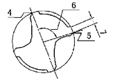
4:軸心を通り両切刃コーナーを結ぶ線
5:工具軸心とヒール側マージンを結ぶ線
6:ヒール側マージンの位置を示す角度
7:ヒール側のマージン巾
R1:切刃側溝底に内接する略円弧の半径
W:ドリル心厚
1: substantially arc corresponding to core thickness 2: blade-side groove bottom 3: generally arc inscribed in the blade-side groove bottom 4: line connecting both cutting edge corners through the axis 5: line connecting the tool axis and the heel side margin 6 : Angle indicating the position of the heel side margin 7: Margin width on the heel side R1: Radius of a substantially arc inscribed in the bottom of the groove on the cutting edge side W: Thickness of the drill core
Claims (5)
5. The drill according to claim 1, wherein the drill is coated with a hard film and / or a lubricating film.
Priority Applications (1)
| Application Number | Priority Date | Filing Date | Title |
|---|---|---|---|
| JP2004283251A JP2006095628A (en) | 2004-09-29 | 2004-09-29 | Twist drill |
Applications Claiming Priority (1)
| Application Number | Priority Date | Filing Date | Title |
|---|---|---|---|
| JP2004283251A JP2006095628A (en) | 2004-09-29 | 2004-09-29 | Twist drill |
Publications (1)
| Publication Number | Publication Date |
|---|---|
| JP2006095628A true JP2006095628A (en) | 2006-04-13 |
Family
ID=36235931
Family Applications (1)
| Application Number | Title | Priority Date | Filing Date |
|---|---|---|---|
| JP2004283251A Pending JP2006095628A (en) | 2004-09-29 | 2004-09-29 | Twist drill |
Country Status (1)
| Country | Link |
|---|---|
| JP (1) | JP2006095628A (en) |
Cited By (2)
| Publication number | Priority date | Publication date | Assignee | Title |
|---|---|---|---|---|
| CN103381495A (en) * | 2012-05-03 | 2013-11-06 | 李仕清 | Combination cutting drill tool bit |
| CN103381497A (en) * | 2012-05-03 | 2013-11-06 | 李仕清 | Centering spiral cutter for combined positioning and combined cutting |
-
2004
- 2004-09-29 JP JP2004283251A patent/JP2006095628A/en active Pending
Cited By (2)
| Publication number | Priority date | Publication date | Assignee | Title |
|---|---|---|---|---|
| CN103381495A (en) * | 2012-05-03 | 2013-11-06 | 李仕清 | Combination cutting drill tool bit |
| CN103381497A (en) * | 2012-05-03 | 2013-11-06 | 李仕清 | Centering spiral cutter for combined positioning and combined cutting |
Similar Documents
| Publication | Publication Date | Title |
|---|---|---|
| EP3444059B1 (en) | Small-diameter drill bit | |
| KR890000210B1 (en) | Cemented carbide drill bit | |
| US20080152438A1 (en) | Ballnose end mill | |
| EP3682993B1 (en) | Small-diameter drill and small-diameter drill manufacturing method | |
| JP2011073129A (en) | Boring drill | |
| JP2006281407A (en) | Machining drill for nonferrous metal | |
| JP2012030306A (en) | Drill and drilling method using the same | |
| US10821526B2 (en) | Rotary tool and method for manufacturing machined product | |
| JP5549080B2 (en) | drill | |
| JP3337804B2 (en) | End mill | |
| JP2010094766A (en) | Boring tool | |
| JP2006095628A (en) | Twist drill | |
| KR101000863B1 (en) | Twist dril | |
| JP2007290105A (en) | End mill | |
| JP2007229900A (en) | Drill | |
| JP2006212725A (en) | Drill for high efficiency machining of aluminum | |
| JP2003039218A (en) | Drill for deep hole | |
| JP2005205526A (en) | Deep hole boring tool | |
| JP7386339B2 (en) | Manufacturing method for drills and cutting products | |
| JP2002066823A (en) | Twist drill | |
| JP2005288669A (en) | Three-groove drill with oil hole | |
| JP2001328015A (en) | Twist drill | |
| JP2002066822A (en) | Twist drill | |
| JP2001170810A (en) | Twist drill | |
| JP2006224213A (en) | Twist drill |
Legal Events
| Date | Code | Title | Description |
|---|---|---|---|
| A977 | Report on retrieval |
Free format text: JAPANESE INTERMEDIATE CODE: A971007 Effective date: 20070827 |
|
| A131 | Notification of reasons for refusal |
Effective date: 20070830 Free format text: JAPANESE INTERMEDIATE CODE: A131 |
|
| A521 | Written amendment |
Free format text: JAPANESE INTERMEDIATE CODE: A523 Effective date: 20071003 |
|
| A02 | Decision of refusal |
Free format text: JAPANESE INTERMEDIATE CODE: A02 Effective date: 20080331 |
|
| A521 | Written amendment |
Effective date: 20080428 Free format text: JAPANESE INTERMEDIATE CODE: A523 |
|
| A911 | Transfer of reconsideration by examiner before appeal (zenchi) |
Effective date: 20080603 Free format text: JAPANESE INTERMEDIATE CODE: A911 |
|
| A912 | Removal of reconsideration by examiner before appeal (zenchi) |
Effective date: 20080919 Free format text: JAPANESE INTERMEDIATE CODE: A912 |
|
| A521 | Written amendment |
Free format text: JAPANESE INTERMEDIATE CODE: A523 Effective date: 20090522 |
|
| A521 | Written amendment |
Effective date: 20090918 Free format text: JAPANESE INTERMEDIATE CODE: A523 |