JP2006088887A - Pneumatic booster - Google Patents
Pneumatic booster Download PDFInfo
- Publication number
- JP2006088887A JP2006088887A JP2004277083A JP2004277083A JP2006088887A JP 2006088887 A JP2006088887 A JP 2006088887A JP 2004277083 A JP2004277083 A JP 2004277083A JP 2004277083 A JP2004277083 A JP 2004277083A JP 2006088887 A JP2006088887 A JP 2006088887A
- Authority
- JP
- Japan
- Prior art keywords
- valve body
- negative pressure
- valve
- poppet
- pressure chamber
- Prior art date
- Legal status (The legal status is an assumption and is not a legal conclusion. Google has not performed a legal analysis and makes no representation as to the accuracy of the status listed.)
- Pending
Links
Images


Abstract
Description
本発明は、車両のブレーキ系統に用いられる気圧式倍力装置に関する。 The present invention relates to a pneumatic booster used in a vehicle brake system.
気圧式倍力装置の一例として、図4に示すようなものがある(特許文献1参照)。図4に示す気圧式倍力装置1は、シェル本体2内を定圧室3と変圧室4とに区画するパワーピストン5と、パワーピストン5に連結したバルブボデー6の筒状部39内に配置され入力ロッド7に連結されたプランジャ8に連動して作動する弁機構9と、を備えている。筒状部39は、シェル本体2を挿通してその後方へ延ばされている。
An example of a pneumatic booster is shown in FIG. 4 (see Patent Document 1). The pneumatic booster 1 shown in FIG. 4 is arranged in a
弁機構9は、大気弁10及び真空弁11を含み、かつ大気弁10及び真空弁11のそれぞれ一部を構成するポペット弁体12を有している。大気弁10は、変圧室4と大気との連通・遮断を行い、真空弁11は、定圧室3と変圧室4との連通・遮断を行うようにしている。ポペット弁体12は、バルブボデー6に固定される略筒状のポペット弁体基端部12aと、ポペット弁体基端部12aに連接される略筒状のベロー部12bと、ベロー部12bの先端側に連結されて後述する大気用弁座20及び負圧用弁座23に離着座する環状の弁体離着座部12cと、を備えている。そして、ベロー部12bの先端側は、弁体離着座部12cの外径側部分に連結されている。
The
また、筒状部39の内部空間(筒状部空間)37における大気弁39の後方領域(以下、筒状部空間後方領域という。)37aは、筒状部39の開口部を介して大気に連通している。
入力ロッド7とバルブボデー6との間にはバルブスプリング15が介在され、入力ロッド7とポペット弁体12の先端部との間にはポペットスプリング16が介在されている。
In addition, a rear region (hereinafter referred to as a tubular portion space rear region) 37 a of the
A
また、バルブスプリング15は、バルブボデー6に対して入力ロッド7を基端側(図4右側)に押し付けるようにしている。ポペットスプリング16は、ポペット弁体12の先端部をプランジャ8(ひいては大気用弁座20)に押し付けるようにしている。真空弁11は、その中心軸を大気弁10の中心軸と同一にして配置され(すなわち、大気弁10と同軸上に配置され)、かつ大気弁10の外側に配置されている(すなわち、真空弁11は、大気弁10に比して径が大きくなっている)。
The
そして、この気圧式倍力装置1は、入力ロッド7に連接されたブレーキペダル(図示省略)が踏込まれると、バルブスプリング15のばね力等に抗して入力ロッド7が前進し、この入力ロッド7の前進により大気弁10が開弁して筒状部空間後方領域37aと変圧室4とが連通し、変圧室4に大気を導入する。この変圧室4への大気導入により定圧室3と変圧室4との間に圧力差を発生させ、この圧力差によってパワーピストン5に生じた推力をリアクションディスク21を介して出力ロッド22に作用させるとともに、出力ロッド22からリアクションディスク21に作用する反力の一部を入力ロッド7に伝達するようにしている。
そして、入力ロッド7の前進停止やパワーピストン5(バルブボデー6)の前進に伴い、バルブボデー6が入力ロッド7に対して相対的に所定量前進することにより、大気弁10が閉弁し、バランス状態となる。
In the pneumatic booster 1, when a brake pedal (not shown) connected to the
As the
上述したブレーキペダルに対する踏力が解放されると、入力ロッド7がバルブスプリング15のばね力によって後退すると共に、プランジャ8も後退する。これにより、ポペット弁体12がプランジャ8に押されてバルブボデー6の内側に設けられた真空弁11の弁座(以下、負圧用弁座という。)23が開き、変圧室4内に負圧通路24及び大気通路25を経て負圧が導入され、上述した圧力差が解消される。その後は、定圧室3内の復帰ばね26のばね力によりバルブボデー6が後退し、バルブボデー6に形成した半径方向孔27aに挿入されたストップキー27がリヤシェル28内の段差面29に当接する原位置にパワーピストン5が復帰し、これと同時にプランジャ8も原位置に復帰して、前記真空弁11も閉じる。
When the pedaling force on the brake pedal is released, the
前記負圧通路24は、一端側が定圧室3に連通し他端側が筒状部39の内周面に開口してバルブボデ6ーに形成されている。負圧通路24の他端側の開口部(以下、負圧通路開口部という。)24aは、ポペット弁体12の外周側に臨んで配置されている。負圧通路開口部24aのリアクションディスク21側方向の縁部が真空弁11の負圧用弁座23とされており、負圧用弁座23に対して弁体離着座部12cの外周側部分が離着座するようになっている。そして、筒状部39及びポペット弁体12により形成される空間(以下、ポペット弁体外周側空間という。)70は、弁体離着座部12cが負圧用弁座23に着座した状態で負圧通路24に連通している。
The
上述したように入力ロッド7の前進により大気弁10を開作動する際には、バルブスプリング15のセット荷重(ばね力)等で定まり大気弁10を開く時に必要な力(以下、無効入力という。)以上の力が入力ロッド7に加わることにより、大気弁10の開弁が果たされる。また、バルブスプリング15及びポペットスプリング16は、そのセット荷重(ばね力)が、負圧状態の定圧室3又は負圧が導入される変圧室4の内圧と大気との圧力差に抗するように設定されるようになっている。
ところで、近時、気圧式倍力装置では、これと共に用いられるマスタシリンダのロングストローク化に合わせて、ロングストローク化を図ることが望まれている。そして、気圧式倍力装置についてロングストローク化を図ると、マスタシリンダに対するストローク及びペダル操作量の関係を良好な状態に維持する上でペダル比を下げる(低ペダル比化を図る)必要がある。 By the way, recently, in a pneumatic booster, it is desired to achieve a longer stroke in accordance with a longer stroke of a master cylinder used therewith. When a long stroke is achieved for the pneumatic booster, it is necessary to lower the pedal ratio (to reduce the pedal ratio) in order to maintain a good relationship between the stroke with respect to the master cylinder and the pedal operation amount.
しかしながら、低ペダル比化を図ると、従来構造の気圧式倍力装置では初期ペダル踏力の増加(ひいては無効入力の増加)を招き、その分、ペダル操作性が悪化し不便となる。そして、このように悪化するペダル操作性の改善のために、無効入力の低減を図ることが考えられる。しかし、無効入力は、その大部分が、上述したように負圧状態の定圧室又は負圧が導入される変圧室の内圧と大気との圧力差に抗するように設定されるバルブスプリング及びポペットスプリングのセット荷重(ばね力)であり、その低減を適切に図ることは容易ではなかった。
このため、低ペダル比化すなわちロングストローク化を適切に果たすことができないというのが実情であった。
However, when the pedal ratio is reduced, the pressure booster having the conventional structure increases the initial pedal effort (and consequently increases the invalid input), and the pedal operability is deteriorated accordingly, which is inconvenient. In order to improve the pedal operability that deteriorates in this way, it is conceivable to reduce the invalid input. However, most of the invalid inputs are valve springs and poppets that are set to resist the pressure difference between the internal pressure of the constant pressure chamber in the negative pressure state or the variable pressure chamber into which the negative pressure is introduced as described above and the atmosphere. It is the set load (spring force) of the spring, and it was not easy to reduce it appropriately.
For this reason, the actual situation is that a low pedal ratio, that is, a long stroke cannot be properly achieved.
本発明は、上記事情に鑑みてなされたものであり、ロングストローク化の達成をペダル踏力の増加を招くことなく図ることができる気圧式倍力装置を提供することを目的とする。 The present invention has been made in view of the above circumstances, and an object of the present invention is to provide a pneumatic booster that can achieve a long stroke without causing an increase in pedal effort.
請求項1記載の発明は、シェル本体内をパワーピストンにより定圧室と変圧室とに区画し、前記パワーピストンに連結したバルブボデーの筒状部を前記シェル本体を挿通してその後方へ延ばし、前記バルブボデー内に、入力ロッドに連結されたプランジャに連動する弁機構を配設し、前記バルブボデーに、一端側が前記定圧室に連通し他端側が前記筒状部の内周面に負圧通路開口部として開口する負圧通路を設け、前記入力ロッドが前進することに伴い前記弁機構が作動し前記筒状部の開口部を通して前記変圧室に大気を導入して前記定圧室と前記変圧室との間に圧力差を発生させ、この圧力差によって前記パワーピストンを推進する気圧式倍力装置であって、前記負圧通路開口部は、前記入力ロッドの基端側に向けて開口し、前記弁機構は、前記プランジャの後端に形成された環状の大気用弁座と、前記負圧通路開口部の周状縁部に形成された負圧用弁座と、前記大気用弁座及び前記負圧用弁座に離着座可能に配設されたポペット弁体と、を備え、前記ポペット弁体は、前記負圧用弁座に対する離着座により前記負圧通路開口部を開閉し、前記負圧通路開口部に対向する前記ポペット弁体の背面領域における前記筒状部及び前記ポペット弁体により囲まれるポペット弁体背面側空間は、前記変圧室に連通していることを特徴とする。 The invention according to claim 1 divides the inside of the shell body into a constant pressure chamber and a variable pressure chamber by a power piston, and extends the tubular portion of the valve body connected to the power piston to the rear thereof through the shell body, A valve mechanism linked to a plunger connected to an input rod is disposed in the valve body, and one end side of the valve body communicates with the constant pressure chamber, and the other end side has a negative pressure on the inner peripheral surface of the cylindrical portion. A negative pressure passage that opens as a passage opening is provided, and the valve mechanism is operated as the input rod moves forward, and the atmosphere is introduced into the variable pressure chamber through the opening of the cylindrical portion, thereby the constant pressure chamber and the variable pressure chamber. A pressure booster that generates a pressure difference with the chamber and propels the power piston by this pressure difference, wherein the negative pressure passage opening opens toward the proximal end of the input rod. The valve mechanism is An annular atmospheric valve seat formed at the rear end of the plunger, a negative pressure valve seat formed at a peripheral edge of the negative pressure passage opening, the atmospheric valve seat and the negative pressure valve seat A poppet valve body disposed so as to be separable, and the poppet valve body opens and closes the negative pressure passage opening by facing the negative pressure valve seat and faces the negative pressure passage opening. The poppet valve body back side space surrounded by the tubular portion and the poppet valve body in the back region of the poppet valve body communicates with the variable pressure chamber.
請求項2記載の発明は、請求項1記載の気圧式倍力装置において、前記ポペット弁体は、前記バルブボデーの筒状部に、該筒状部の内部に設けられる筒体を介して固定される略筒状のポペット弁体基端部と、ポペット弁体基端部に連接される略筒状のベロー部と、該ベロー部の先端側に連結されて前記大気用弁座及び前記負圧用弁座に離着座する環状の弁体離着座部と、該弁体離着座部を前記大気用弁座及び負圧用弁座に着座する方向に押付けるポペットスプリングと、を備え、前記ベロー部の先端側の前記弁体離着座部に対する連結は、前記弁体離着座部の内径側部分で行われていること特徴とする。
請求項3記載の発明は、請求項1又は2記載の気圧式倍力装置において、前記ポペットスプリングは、前記弁体離着座部と前記筒状部との間に介在することを特徴とする。
According to a second aspect of the present invention, in the pneumatic booster according to the first aspect, the poppet valve body is fixed to the tubular portion of the valve body via a tubular body provided inside the tubular portion. A substantially cylindrical poppet valve body base end portion, a substantially cylindrical bellows portion connected to the poppet valve body base end portion, and connected to a distal end side of the bellows portion to connect the atmospheric valve seat and the negative valve seat An annular valve body seat for seating on and off from the pressure valve seat; and a poppet spring that presses the valve body seat on the air valve seat and the negative pressure valve seat in the direction of seating. The connection of the front end side to the valve body seating part is performed at the inner diameter side portion of the valve body seating part.
According to a third aspect of the present invention, in the pneumatic booster according to the first or second aspect, the poppet spring is interposed between the valve body seating portion and the cylindrical portion.
請求項1記載の発明によれば、倍力作用の開始に際し、負圧通路は負圧状態とされていてかつポペット弁体背面側空間と遮断されており、入力ロッドの前進により大気弁が開弁すると、変圧室に大気が導入されて定圧室と変圧室との間に圧力差が生じてパワーピストンが推進する一方、ポペット弁体背面側空間に大気が導入され、これに伴いポペット弁体は負圧通路側、すなわち負圧用弁座を閉弁する方向に押えられる。このため、大気弁を開弁した際に、真空弁を閉弁状態に維持するために必要とされるばね力を、その分、小さくでき、ひいては無効入力を小さくできる。そして、このように無効入力を小さくできることから、ロングストローク化に付随して必要とされる低ペダル比化を行っても、ペダル踏力を増加させなくて済むことになる。換言すれば、ペダル踏力を増加させずにロングストローク化(ひいてはこれに伴う低ペダル比化)を図ることができるようになる。 According to the first aspect of the invention, when the boosting action is started, the negative pressure passage is in a negative pressure state and is blocked from the space behind the poppet valve body, and the atmospheric valve is opened by the advancement of the input rod. When the valve is operated, the atmosphere is introduced into the variable pressure chamber and a pressure difference is generated between the constant pressure chamber and the variable pressure chamber, and the power piston is propelled. On the other hand, the air is introduced into the space behind the poppet valve body. Is pressed in the direction of closing the negative pressure passage side, that is, the negative pressure valve seat. For this reason, when the atmospheric valve is opened, the spring force required to maintain the vacuum valve in the closed state can be reduced correspondingly, and the invalid input can be reduced accordingly. Since the invalid input can be reduced in this way, it is not necessary to increase the pedal effort even when the pedal ratio is reduced as required along with the longer stroke. In other words, it is possible to achieve a long stroke (and consequently a low pedal ratio) without increasing the pedal effort.
請求項2記載の発明によれば、ベロー部の先端側の弁体離着座部に対する連結は、弁体離着座部の内径側部分で行われているので、ポペット弁体背面側空間を広く取ることができ、ポペット弁体背面側空間にポペットスプリングを配置するスペースを確保することができる。
請求項3記載の発明によれば、ポペットスプリングは、弁体離着座部と筒状体との間に介在されており、ポペットスプリングのばね力は、負圧用弁座に対して押し付け力として働き、確実なシール性を有することになる。また、大気が変圧室に導入される時、ポペットスプリングを通らないので、空気連通音を低減することができる。
According to the second aspect of the present invention, since the connection to the valve body seating portion on the tip side of the bellows portion is performed at the inner diameter side portion of the valve body seating portion, the space on the back surface of the poppet valve body is widened. It is possible to secure a space for disposing the poppet spring in the space behind the poppet valve body.
According to the third aspect of the present invention, the poppet spring is interposed between the valve body separating seat and the tubular body, and the spring force of the poppet spring acts as a pressing force against the negative pressure valve seat. It will have a reliable sealing property. In addition, since the poppet spring does not pass through when the atmosphere is introduced into the variable pressure chamber, air communication noise can be reduced.
以下、本発明の第1実施の形態に係る気圧式倍力装置1Aを図1及び図2に基づいて説明する。
図1及び図2において、気圧式倍力装置1Aは、フロントシェル30とリヤシェル28とからなるシェル本体2を備えると共に、このシェル本体2内に、この内部を定圧室3と変圧室4とに区画するパワーピストン5を配設している。パワーピストン5は、ダイアフラム35に保持されており、その中心部には、軸孔36及び筒状部空間37を形成したバルブボデー6が設けられている。
Hereinafter, a
1 and 2, the pneumatic booster 1 </ b> A includes a
バルブボデー6は、軸孔36及び筒状部空間37の一部が形成された大径の本体部(以下、バルブボデー本体部という。)38と、筒状部空間37の大部分が形成された小径の筒状部39とを連接してなっており、その筒状部39が、リヤシェル28の後部の小径筒部40を気密的にかつ摺動自在に挿通してその後方まで延ばされている。筒状部39は、その開口部(以下、筒状部開口部という。)39a側の筒状部先端側部分39Aと、筒状部先端側部分39Aの筒状部開口部39aと反対側の筒状部基端側部分39Bと、からなっている。筒状部基端側部分39Bは、バルブボデー本体部38に連接されている。また、筒状部基端側部分39Bは、筒状部先端側部分39Aに比して厚さ寸法が大きくされている。
The
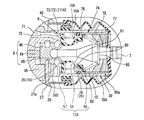
バルブボデー6には、一端側が定圧室3に連通し他端側が筒状部39の内周面に開口する負圧通路71(定圧通路)を設けられている。負圧通路71の他端側の開口部(以下、負圧通路開口部という。)72は、筒状部基端側部分39Bから筒状部先端側部分39Aに向けて略筒状に突出し、入力ロッド7の基端側に(図2右方向に、図3紙面手前に)向けて開口し、ポペット弁体12Aの弁体離着座部57に臨んで配置されている。負圧通路71は、図3に示すように2本形成されており、これに対応して負圧通路開口部72も2つ設けられている。負圧通路開口部72のリング状の縁部が負圧用弁座73を形成しており、弁体離着座部57が離着座し得るようになっている。換言すれば弁体離着座部57は、負圧用弁座73に対する離着座により負圧通路開口部72を開閉するようになっている。
そして、この場合、負圧通路開口部72に対向する弁体離着座部57(ポペット弁体12A)の背面領域における筒状部39、筒状部内筒体74及びポペット弁体12Aにより囲まれる空間(以下、ポペット弁体背面側空間という。)70Aは、大気通路25を通して変圧室4に連通している一方、弁体離着座部57が負圧用弁座73に着座した状態で負圧通路71との連通が遮断されることになる。
The
In this case, the space surrounded by the
筒状部先端側部分39Aには、前記筒状部内筒体74が嵌合されている。筒状部内筒体74は、筒体本体75と、筒体本体75の一端側に連接し筒体本体75に比して厚さ寸法が大きい筒体肉厚部76と、筒体本体75の他端側に径方向外方に突出形成され、筒状部開口部39aに当接してバルブボデー6に対する位置決めに用いられる筒体第1フランジ77と、から大略構成されている。
筒体肉厚部76の外周側にはOリング78を収納してこれを固定する環状溝79が形成されている。
筒体肉厚部76の前方側(図2左方向)には、径方向内方に突出する筒体第2フランジ80が形成されており、筒体肉厚部76の内周側に嵌合されるポペット弁体12Aのポペット弁体基端部55をシールすると共に、ポペット弁体12Aの抜け止めを行うようにしている。
The tubular portion
An
A cylindrical
筒体第2フランジ80には、前方(図2左方向)に突出する環状突起81が形成されており、ポペットスプリング16Aの一端部を係止するようにしている。
また、筒状部39内には、ポペット弁体12Aのポペット弁体基端部55を内周側から押えられるようにポペットリテーナ82が配置されている。ポペットリテーナ82は、ポペット弁体基端部55を上記筒体肉厚部76に固定すると共に、バルブスプリング15を係止するようにしている。
The cylindrical
Further, a
また、バルブボデー6は、定圧室3内に配設した復帰ばね26により、常時はリヤ側(図1右側)へ付勢され、本気圧式倍力装置1Aの非作動時には、半径方向孔27aに挿入したストップキー27をリヤシェル28の小径筒部40の内側の段差面29に当接させる原位置に位置決めされるようになっている。
定圧室3内には、フロントシェル30に設けた通気口41を通じて、例えばエンジン負圧が導入されるようになっており、この負圧は、図示しないブレーキペダルから延ばした入力ロッド7と連動する弁機構9の作動により、負圧通路71と大気通路25とを経て変圧室4にも供給されるようになっている。
The
For example, engine negative pressure is introduced into the
一方、筒状部39の筒状部開口部39a側に配置した筒状部内筒体74内には消音用フィルタ42及び防塵用フィルタ43が配置され、各フィルタ42,43とを通して大気が筒状部空間37に導入されるようになっている。この大気は、弁機構9の作動により大気通路25を経て変圧室4に供給されるようになっている。ここで、消音用フィルタ42及び防塵用フィルタ43は、リング状をなしており、入力ロッド7はこれらフィルタ42、43の内径部を挿通して延ばされている。また、これらフィルタ42、43は、リヤシェル28の小径筒部40に口縁部が嵌着され、バルブボデー6の筒状部39及び筒状部内筒体74を覆う有底筒状のダストブーツ44により抜止めされている。
On the other hand, a
前記弁機構9は、バルブボデー本体部38に形成された軸孔36内に摺動可能に嵌挿されたプランジャ8を備えている。図2に示すように、このプランジャ8の後端部(以下、プランジャ入力ロッド連結部という。)45及び後述するプランジャ本体部48に形成した穴部(符号省略)には、消音用フィルタ42と防塵用フィルタ43とを挿通して延ばした入力ロッド7の先端部(符号省略)が挿入されて連結されている。入力ロッド7は、ブレーキペダルの踏込みに応じて、図1の左方向へ前進し、これと一体にプランジャ8も前進する。
The
プランジャ8は、プランジャ入力ロッド連結部45に、これに比して大径のプランジャ本体部48が連接され、このプランジャ本体部48の前側にはプランジャ入力ロッド連結部45に比して小径の軸部(以下、プランジャ軸部という。)49が延設されている。プランジャ軸部49は、軸孔36に挿通され、その先端面部がリアクションディスク21に当接可能に配置されている。
The
弁機構9は、図2に示すように、プランジャ8の後端(プランジャ入力ロッド連結部45)に形成された環状の大気用弁座20と、前記負圧用弁座73と、前記両弁座20、23に離着座可能に筒状部39内(筒状部空間37)に配設されたポペット弁体12Aと、筒体肉厚部76に一端が係止され、常時はポペット弁体12A(弁体離着座部57)を両弁座20、23に着座する方向に押付けるポペットスプリング16Aとを備えている。ポペットスプリング16Aは、図2にも示されるようにポペット弁体12Aの背面側(ポペット弁体背面側空間70A)に配置されている。
As shown in FIG. 2, the
ポペット弁体12Aは、バルブボデー6に上記筒状部内筒体74を介して固定される略筒状の前記ポペット弁体基端部55と、ポペット弁体基端部55の内周端側に基端側が連接される略筒状のベロー部56と、ベロー部56の先端側に設けられる略環状の前記弁体離着座部57と、から大略構成されている。ベロー部56は、先端側から基端側に向けて緩やかに拡径しており、ポペット弁体背面側空間70Aと筒状部空間37との間に配置されるようになっている。また、ポペット弁体基端部55は、上述したように筒体肉厚部76に固定されるので、従来よりも筒状部39の内周側で固定されるようになっている。本実施の形態では、ポペット弁体基端部55、ベロー部56及び弁体離着座部57は、同一の可撓性材料で一体に構成されている。
The
弁機構9は、大気用弁座20とこれに当接するポペット弁体12Aの弁体離着座部57の前面側(図2左側)における内周側部分(符号省略)とで大気弁10を構成し、負圧用弁座73とこれに当接するポペット弁体12Aの弁体離着座部57の前面側(図2左側)における外周側部分(符号省略)とで真空弁11Aを構成し、前記変圧室4には、これら大気弁10または真空弁11Aの開弁に応じて大気または負圧が選択的に供給されるようになる。
大気弁10は、上述したように構成されて変圧室4と大気との連通・遮断を行い、真空弁11Aは、上述したように構成されて定圧室3と変圧室4との連通・遮断を行うようにしている。
The
The
ここで、弁機構9を構成するポペット弁体12Aは、入力ロッド7をリヤ側へ付勢するバルブスプリング15の一端を受けるポペットリテーナ82によりバルブボデー6に対して固定されている。このバルブスプリング15の他端は入力ロッド7に一体に設けたつば部66に係止されており、これにより入力ロッド7は、常時はリヤ側への戻り方向へ付勢され、この動きにプランジャ8も連動する。プランジャ8は、バルブボデー6の半径方向孔27aに挿入されたストップキー27によりバルブボデー6に対する相対移動範囲が規制されており、本気圧式倍力装置1Aの非作動時には、図1に示すように、ストップキー27によりプランジャ8の戻り端が規制され、ポペット弁体12Aは、大気用弁座20及び負圧用弁座73に当接する閉弁状態を維持するようになる。
Here, the
一方、バルブボデー6の前端側には、リアクションディスク21と出力ロッド22の基端カップ部68とが配置されており、プランジャ8のプランジャ軸部49の先端がリアクションディスク21の背面に対してわずかの間隙を開けるように位置決めされている。出力ロッド22の先端部は、定圧室3を通し、かつフロントシェル30を挿通して、図示を略すマスタシリンダ内のピストンが作動連結されるようになっている。なお、出力ロッド22の基端カップ部68とリアクションディスク21とは、復帰ばね26によりバルブボデー6の前端に押圧固定されたリテーナ69により抜止めされている。
On the other hand, the
以下、本気圧式倍力装置1Aの作用を説明する。
本気圧式倍力装置1Aは、そのリヤシェル28の後面に突設した複数のスタッドボルト80を利用して図示しない車体に取付けられる一方で、そのフロントシェル30の前面に突設したスタッドボルト81を利用して、図示を略すマスタシリンダが本気圧式倍力装置1Aに結合される。
Hereinafter, the operation of the
The
そして、この取付状態でブレーキペダル(図示せず)が踏込まれると、入力ロッド7が前進してプランジャ8が前進し、プランジャ8の後端の大気用弁座20がポペット弁体12Aから離間して大気弁10が開く。これにより、消音用フィルタ42及び防塵用フィルタ43を通してバルブボデー6内に大気が流入し、この大気は、さらに大気弁10から大気通路25を経て変圧室4に導入される。この結果、負圧が導入されている定圧室3と大気が導入された変圧室4との間に圧力差が発生し、この圧力差によりバルブボデー6を含むパワーピストン5が推進し、その推力がバルブボデー6から出力ロッド22を経てマスタシリンダ側へ出力される。一方、前記出力による反力の一部が、出力ロッド22からリアクションディスク21及びプランジャ8を経て入力ロッド7に伝達され、これにより入力の増大に応じて出力が上昇する倍力作用が行われる。
When a brake pedal (not shown) is depressed in this attached state, the
そして、この倍力作用の開始に際しては、大気弁10が開弁した際には、負圧状態とされている負圧通路71はポペット弁体背面側空間70Aと遮断されている一方、ポペット弁体背面側空間70Aには大気が導入される。そして、負圧通路71及びポペット弁体背面側空間70Aによる差圧により、弁体離着座部57は負圧通路71側、すなわち負圧用弁座73を閉弁する方向の圧力を受ける。この結果、大気弁10を開弁した際に、真空弁11Aを閉弁させるために必要とされるばね力を小さくでき、ひいては無効入力を小さくできる。
そして、このように無効入力を小さくできることから、ロングストローク化に付随して必要とされる低ペダル比化を行っても、ペダル踏力を増加させなくて済むことになる。換言すれば、ペダル踏力を増加させずにロングストローク化(ひいてはこれに伴う低ペダル比化)を図ることができるようになる。
At the start of this boosting action, when the
Since the invalid input can be reduced in this way, it is not necessary to increase the pedal effort even when the pedal ratio is reduced as required along with the longer stroke. In other words, it is possible to achieve a longer stroke (and consequently a lower pedal ratio) without increasing the pedal effort.
また、ベロー部56の先端側が、弁体離着座部57の内径側部分に連結されているので、ポペット弁体背面側空間70Aを広く取ることができ、ポペットスプリング16Aをポペット弁体背面側空間70Aに配置するスペースを確保することができる。また、ベロー部56の有効半径を従来よりも小さくできるので、ベロー部56に作用する差圧の面積が小さくなる。その分、差圧力が小さくなるためバルブスプリング力を小さくでき、結果的に無効入力を小さくすることができる。本実施の形態では、このように広くされたポペット弁体背面側空間70Aにポペットスプリング16Aを配置し、ポペットスプリング16Aを筒体肉厚部76及び弁体離着座部57間に介在させている。このため、ポペットスプリング16Aのばね力は、真空弁11Aに対し、確実に押し付け力として働きシール性を確実にできる。また、大気が、変圧室4に導入される時、ポペットスプリング16Aを通らないので、空気連通音低減の効果がある。
Moreover, since the front end side of the
また、上記実施の形態においては、1つのパワーピストン5を備えた、いわゆるシングル型として気圧式倍力装置1Aを構成したが、本発明は、2つのパワーピストンを備えたタンデム型として構成してもよいことはもちろんである。
Moreover, in the said embodiment, although the
1A…気圧式倍力装置、2…シェル本体、3…定圧室、4…変圧室、5…パワーピストン、6…バルブボデー、7…入力ロッド、8…プランジャ、9…弁機構、10…大気弁、11A…真空弁、12A…ポペット弁体、15…バルブスプリング、16A…ポペットスプリング、20…大気用弁座、21…リアクションディスク、39…筒状部、56…ベロー部、57…弁体離着座部、70A…ポペット弁体背面側空間、71…負圧通路、72…負圧通路開口部、73…負圧用弁座。
DESCRIPTION OF
Claims (3)
前記負圧通路開口部は、前記入力ロッドの基端側に向けて開口し、
前記弁機構は、前記プランジャの後端に形成された環状の大気用弁座と、前記負圧通路開口部の周状縁部に形成された負圧用弁座と、前記大気用弁座及び前記負圧用弁座に離着座可能に配設されたポペット弁体と、を備え、
前記ポペット弁体は、前記負圧用弁座に対する離着座により前記負圧通路開口部を開閉し、
前記負圧通路開口部に対向する前記ポペット弁体の背面領域における前記筒状部及び前記ポペット弁体により囲まれるポペット弁体背面側空間は、前記変圧室に連通していることを特徴とする気圧式倍力装置。 The inside of the shell body is divided into a constant pressure chamber and a variable pressure chamber by a power piston. A valve mechanism that is linked to a plunger connected to the valve body, and a negative pressure that opens to the valve body as a negative pressure passage opening at one end side communicating with the constant pressure chamber and at the other end side to the inner peripheral surface of the cylindrical portion. As the input rod moves forward, the valve mechanism is actuated to introduce the atmosphere into the variable pressure chamber through the opening of the cylindrical portion, thereby creating a pressure difference between the constant pressure chamber and the variable pressure chamber. A pneumatic booster that generates and propels the power piston by this pressure difference,
The negative pressure passage opening opens toward the base end side of the input rod,
The valve mechanism includes an annular atmospheric valve seat formed at a rear end of the plunger, a negative pressure valve seat formed at a circumferential edge of the negative pressure passage opening, the atmospheric valve seat, and the A poppet valve body disposed on the negative pressure valve seat so as to be separable; and
The poppet valve body opens and closes the negative pressure passage opening by means of a release seat with respect to the negative pressure valve seat,
The space on the back side of the poppet valve body surrounded by the tubular portion and the poppet valve body in the back region of the poppet valve body facing the negative pressure passage opening portion is in communication with the variable pressure chamber. Pneumatic booster.
3. The pneumatic booster according to claim 1, wherein the poppet spring is interposed between the valve body attaching / detaching seat portion and the cylindrical portion.
Priority Applications (2)
| Application Number | Priority Date | Filing Date | Title |
|---|---|---|---|
| JP2004277083A JP2006088887A (en) | 2004-09-24 | 2004-09-24 | Pneumatic booster |
| CNB2005101068500A CN100526134C (en) | 2004-09-24 | 2005-09-26 | Pneumatic booster |
Applications Claiming Priority (1)
| Application Number | Priority Date | Filing Date | Title |
|---|---|---|---|
| JP2004277083A JP2006088887A (en) | 2004-09-24 | 2004-09-24 | Pneumatic booster |
Publications (2)
| Publication Number | Publication Date |
|---|---|
| JP2006088887A true JP2006088887A (en) | 2006-04-06 |
| JP2006088887A5 JP2006088887A5 (en) | 2007-08-16 |
Family
ID=36230266
Family Applications (1)
| Application Number | Title | Priority Date | Filing Date |
|---|---|---|---|
| JP2004277083A Pending JP2006088887A (en) | 2004-09-24 | 2004-09-24 | Pneumatic booster |
Country Status (2)
| Country | Link |
|---|---|
| JP (1) | JP2006088887A (en) |
| CN (1) | CN100526134C (en) |
Cited By (1)
| Publication number | Priority date | Publication date | Assignee | Title |
|---|---|---|---|---|
| JP2019217898A (en) * | 2018-06-19 | 2019-12-26 | ボッシュ株式会社 | Negative pressure type brake booster |
Citations (7)
| Publication number | Priority date | Publication date | Assignee | Title |
|---|---|---|---|---|
| JPS6280150A (en) * | 1985-09-30 | 1987-04-13 | ベンデイクス・フランス | Brake booster |
| JPH05178202A (en) * | 1991-12-27 | 1993-07-20 | Tokico Ltd | Pneumatic booster |
| JPH08500307A (en) * | 1992-08-22 | 1996-01-16 | アイティーティー・オートモーティブ・ヨーロップ・ゲーエムベーハー | Negative pressure braking force booster for automobiles |
| JPH10508265A (en) * | 1994-09-08 | 1998-08-18 | アライドシグナル ウーロープ セルビス テクニック | Pneumatic booster with reduced load and hysteresis |
| JPH11507888A (en) * | 1995-06-08 | 1999-07-13 | ボッシュ システム ド フラナージュ | Booster device with simplified compensation volume |
| JP2002187540A (en) * | 2000-12-20 | 2002-07-02 | Nissin Kogyo Co Ltd | Negative pressure booster |
| JP2003191834A (en) * | 2001-12-27 | 2003-07-09 | Bosch Automotive Systems Corp | Negative pressure booster |
-
2004
- 2004-09-24 JP JP2004277083A patent/JP2006088887A/en active Pending
-
2005
- 2005-09-26 CN CNB2005101068500A patent/CN100526134C/en not_active Expired - Fee Related
Patent Citations (7)
| Publication number | Priority date | Publication date | Assignee | Title |
|---|---|---|---|---|
| JPS6280150A (en) * | 1985-09-30 | 1987-04-13 | ベンデイクス・フランス | Brake booster |
| JPH05178202A (en) * | 1991-12-27 | 1993-07-20 | Tokico Ltd | Pneumatic booster |
| JPH08500307A (en) * | 1992-08-22 | 1996-01-16 | アイティーティー・オートモーティブ・ヨーロップ・ゲーエムベーハー | Negative pressure braking force booster for automobiles |
| JPH10508265A (en) * | 1994-09-08 | 1998-08-18 | アライドシグナル ウーロープ セルビス テクニック | Pneumatic booster with reduced load and hysteresis |
| JPH11507888A (en) * | 1995-06-08 | 1999-07-13 | ボッシュ システム ド フラナージュ | Booster device with simplified compensation volume |
| JP2002187540A (en) * | 2000-12-20 | 2002-07-02 | Nissin Kogyo Co Ltd | Negative pressure booster |
| JP2003191834A (en) * | 2001-12-27 | 2003-07-09 | Bosch Automotive Systems Corp | Negative pressure booster |
Cited By (2)
| Publication number | Priority date | Publication date | Assignee | Title |
|---|---|---|---|---|
| JP2019217898A (en) * | 2018-06-19 | 2019-12-26 | ボッシュ株式会社 | Negative pressure type brake booster |
| JP7038609B2 (en) | 2018-06-19 | 2022-03-18 | ボッシュ株式会社 | Negative pressure type brake booster |
Also Published As
| Publication number | Publication date |
|---|---|
| CN1751926A (en) | 2006-03-29 |
| CN100526134C (en) | 2009-08-12 |
Similar Documents
| Publication | Publication Date | Title |
|---|---|---|
| JPH03128756A (en) | Valve assembly body to control air pressure brake booster | |
| JP2006088887A (en) | Pneumatic booster | |
| JP5617815B2 (en) | Negative pressure booster | |
| US4524584A (en) | Brake booster | |
| US6446537B1 (en) | Vacuum brake booster | |
| JP4608573B2 (en) | Negative pressure booster | |
| JPH1111294A (en) | Pneumatic booster | |
| JP3107886B2 (en) | Pneumatic booster | |
| JP4512032B2 (en) | Negative pressure booster | |
| JPH1044973A (en) | Booster | |
| JP5078796B2 (en) | Negative pressure booster | |
| JP6737205B2 (en) | Brake booster | |
| WO2017130464A1 (en) | Negative-pressure type booster device | |
| JP3661714B2 (en) | Automatic brake booster | |
| JPH0412851Y2 (en) | ||
| JP2006069263A (en) | Pneumatic booster | |
| JPH1086812A (en) | Negative pressure type booster | |
| JP2004058861A (en) | Pneumatic booster | |
| JP2004058959A (en) | Pneumatic booster | |
| JPH0347014Y2 (en) | ||
| JP4380389B2 (en) | Negative pressure booster | |
| JP3358642B2 (en) | Booster | |
| JPH07137626A (en) | Atmospheric pressure type booster | |
| JPH1059164A (en) | Booster | |
| JP2536598Y2 (en) | Pneumatic booster |
Legal Events
| Date | Code | Title | Description |
|---|---|---|---|
| A521 | Written amendment |
Free format text: JAPANESE INTERMEDIATE CODE: A523 Effective date: 20070629 |
|
| A621 | Written request for application examination |
Free format text: JAPANESE INTERMEDIATE CODE: A621 Effective date: 20070629 |
|
| A711 | Notification of change in applicant |
Free format text: JAPANESE INTERMEDIATE CODE: A712 Effective date: 20090902 |
|
| RD03 | Notification of appointment of power of attorney |
Free format text: JAPANESE INTERMEDIATE CODE: A7423 Effective date: 20090902 |
|
| A521 | Written amendment |
Free format text: JAPANESE INTERMEDIATE CODE: A523 Effective date: 20090904 |
|
| A977 | Report on retrieval |
Free format text: JAPANESE INTERMEDIATE CODE: A971007 Effective date: 20090925 |
|
| A131 | Notification of reasons for refusal |
Free format text: JAPANESE INTERMEDIATE CODE: A131 Effective date: 20091007 |
|
| A521 | Written amendment |
Free format text: JAPANESE INTERMEDIATE CODE: A523 Effective date: 20091207 |
|
| A131 | Notification of reasons for refusal |
Free format text: JAPANESE INTERMEDIATE CODE: A131 Effective date: 20100106 |
|
| A521 | Written amendment |
Free format text: JAPANESE INTERMEDIATE CODE: A523 Effective date: 20100308 |
|
| A02 | Decision of refusal |
Free format text: JAPANESE INTERMEDIATE CODE: A02 Effective date: 20100421 |