JP2006084263A - Gas leak inspection device - Google Patents
Gas leak inspection device Download PDFInfo
- Publication number
- JP2006084263A JP2006084263A JP2004267997A JP2004267997A JP2006084263A JP 2006084263 A JP2006084263 A JP 2006084263A JP 2004267997 A JP2004267997 A JP 2004267997A JP 2004267997 A JP2004267997 A JP 2004267997A JP 2006084263 A JP2006084263 A JP 2006084263A
- Authority
- JP
- Japan
- Prior art keywords
- gas
- inspection
- leak
- flow meter
- flow rate
- Prior art date
- Legal status (The legal status is an assumption and is not a legal conclusion. Google has not performed a legal analysis and makes no representation as to the accuracy of the status listed.)
- Granted
Links
- 238000007689 inspection Methods 0.000 title claims abstract description 51
- 239000007789 gas Substances 0.000 description 91
- 238000005259 measurement Methods 0.000 description 17
- 238000010586 diagram Methods 0.000 description 6
- 239000001307 helium Substances 0.000 description 5
- 229910052734 helium Inorganic materials 0.000 description 5
- SWQJXJOGLNCZEY-UHFFFAOYSA-N helium atom Chemical compound [He] SWQJXJOGLNCZEY-UHFFFAOYSA-N 0.000 description 5
- 238000012360 testing method Methods 0.000 description 5
- XLYOFNOQVPJJNP-UHFFFAOYSA-N water Substances O XLYOFNOQVPJJNP-UHFFFAOYSA-N 0.000 description 4
- 230000007423 decrease Effects 0.000 description 2
- 238000000034 method Methods 0.000 description 2
- 230000002159 abnormal effect Effects 0.000 description 1
- 230000005856 abnormality Effects 0.000 description 1
- 238000006243 chemical reaction Methods 0.000 description 1
- 230000003247 decreasing effect Effects 0.000 description 1
- 238000001514 detection method Methods 0.000 description 1
- 238000012423 maintenance Methods 0.000 description 1
- 230000000737 periodic effect Effects 0.000 description 1
- 238000007789 sealing Methods 0.000 description 1
Images


Abstract
Description
本発明は、配管工事等の完成検査時に、完成した配管(付属部品一式すべて含めて)や気密容器に漏れが有るか無いかを、定量的に検査するリーク検査装置に関する。 The present invention relates to a leak inspection apparatus for quantitatively inspecting whether or not there is a leak in a completed pipe (including all accessories) and an airtight container at the time of completion inspection such as piping work.
通常ガス配管を行った場合、完成時の引き渡し時に、配管の気密検査が行われる。配管全体で漏れがないことを確認したのち、気密検査成績書等を提出する。しかし、この検査成績書も指定検査圧力で漏れはありませんといった程度のものであり、指定検査圧力で何cc/min(またはg/sec等)以下の気密性能を有する等と定量的に行われるものではない。 When performing normal gas piping, airtight inspection of the piping is performed at the time of delivery at the time of completion. After confirming that there are no leaks in the entire pipe, submit an airtight inspection report. However, this inspection report is of such a level that there is no leakage at the specified inspection pressure, and it is quantitatively performed as having a hermetic performance of several cc / min (or g / sec, etc.) at the specified inspection pressure. is not.
通常簡単に気密検査をする場合、石鹸水等をかけて泡がでないことを確認し漏れがないことを確認している。また、指定検査圧力で配管にガスを封入し、封止してある程度の時間(数時間から十数時間程度かかる)をおいて、圧力の低下しないことを確認して検査している。しかし、前者の場合は配管が長距離の場合は、非常に大変な作業となり、検査漏れになる場合がある。また、後者の場合圧力をかけて封止しても、一日のうちでは朝夕と日中での気温差や、短時間での気温の変動等があると、温度によるガスの体積変化は非常に大きくなるため、圧力が封止時の初期値と同一になるとは限らず、場合によっては高くなる場合もある。 Usually, when performing an air tightness check, it is confirmed that there are no bubbles by applying soapy water, etc., and there is no leakage. In addition, gas is sealed in piping at a specified inspection pressure, and after a certain amount of time (several hours to several tens of hours) is sealed, it is inspected after confirming that the pressure does not drop. However, in the former case, if the piping is long distance, it is a very difficult work, which may result in an inspection failure. In the latter case, even if pressure is applied and sealed, if there is a difference in temperature between morning and evening in the day, or a change in temperature in a short time, the volume change of the gas due to temperature will be extremely high. Therefore, the pressure is not always the same as the initial value at the time of sealing, and may be increased in some cases.
従来のように、石鹸水をかけて試験したりする場合に、配管が必ずしもいつも検査しやすい位置にあるとは限らず、狭い場所や、手の届かない所、曲がりくねった場所、または配管の裏表で全周に亘って試験しなければならず、実施しにくい場合もある。そして、それを全長に亘って試験しなければならない場合は、非常に大変な作業となる。
特に、リークが危険を招く場合は、より高感度なリーク試験装置として、ヘリウムガスを使用した、ヘリウムリークディテクタ等の高価な装置も市販されている。これは大気中に無いヘリウムガスを使用して、加圧してリーク試験を行い、リークがあればその部分に漏れたヘリウムが存在するため、検出器が反応する様になっているものである。これも石鹸水の泡を目で見る代わりに、ヘリウムガスをディテクタで検出するものである。つまり漏れている部分からでてくるガスが有るか無いかを調べる方法であり、原理的には石鹸水と同じ方法となる。従って、前記と同様に、検査部全体をくまなく検査しなければならず、検査に大変な作業を要する。
When testing with soapy water as in the past, piping is not always in a position that is easy to inspect. In this case, the test must be performed over the entire circumference, which may be difficult to implement. And if it has to be tested over its entire length, it is a very difficult task.
In particular, when a leak causes danger, an expensive apparatus such as a helium leak detector using helium gas is also commercially available as a more sensitive leak test apparatus. In this case, a helium gas not in the atmosphere is used for pressurization and a leak test is performed. If there is a leak, the leaked helium is present in that portion, so that the detector reacts. This also detects helium gas with a detector instead of seeing soapy water bubbles. In other words, it is a method for examining whether or not there is gas coming out from the leaking portion, and in principle it is the same method as soapy water. Therefore, as described above, the entire inspection section must be inspected thoroughly, and inspection requires a great deal of work.
本発明の目的は、上記の問題点に鑑み、気密検査時における被検査対象物のガスリークを簡便な手段で求めることを可能にしたガスリーク検査装置を提供することにある。 In view of the above-described problems, an object of the present invention is to provide a gas leak inspection apparatus capable of obtaining a gas leak of an object to be inspected at an airtight inspection by a simple means.
本発明は、上記の問題を解決するために、下記の手段を採用した。
第1の手段は、配管や気密容器等からなる被検査対象物と、該被検査対象物に一定量のガスを供給するガス定量供給装置と、前記被検査対象物内のガス圧力を制御するガス圧力制御装置と、前記被検査対象物から排出されるガス量を計測する流量計とから構成され、前記被検査対象物におけるあるガス圧力に対する前記流量計におけるガス流量を計測するとともに、前記被検査対象物における他のあるガス圧力に対する前記流量計におけるガス流量とを計測し、前記計測されたガス圧力の差に対する前記ガス流量計の差との比から、気密検査時における被検査対象物のガスリーク量を求めることを特徴とするガスリーク検査装置である。
The present invention employs the following means in order to solve the above problems.
The first means controls an object to be inspected consisting of a pipe, an airtight container, etc., a gas fixed amount supply device for supplying a certain amount of gas to the object to be inspected, and a gas pressure in the object to be inspected. A gas pressure control device; and a flow meter that measures the amount of gas discharged from the object to be inspected, and measures the gas flow rate in the flow meter with respect to a certain gas pressure in the object to be inspected. The gas flow rate in the flow meter with respect to some other gas pressure in the inspection object is measured, and from the ratio of the difference in the gas flow meter with respect to the difference in the measured gas pressure, the inspection object at the time of the airtight inspection A gas leak inspection apparatus characterized by obtaining a gas leak amount.
請求項1に記載の発明によれば、一カ所から一度に被検査対象物である全ラインが測定できる利点が有り、その測定デ−タも流量値(質量流量換算)であるため定量的な表現となる。
また、測定が簡単で全体を一度に検査できるので、被検査対象物としてラインの定期的な保守等にも使用でき、異常が早期に発見でき、ラインを予め何カ所かに分けられるようにバルブを付けて配管を区切るようにすれば、部分毎にチェックができ、異常箇所も迅速に発見できる。
According to the first aspect of the present invention, there is an advantage that all lines that are the objects to be inspected can be measured from one place at a time, and since the measurement data is also a flow rate value (mass flow rate conversion), it is quantitative. It becomes an expression.
In addition, since the measurement is simple and the whole can be inspected at once, it can also be used for periodic maintenance of the line as the object to be inspected, so that abnormalities can be detected early, and the line can be divided into several places in advance. If the pipes are separated by attaching, the check can be made for each part, and the abnormal part can be found quickly.
本発明の実施形態を図1乃至図6を用いて説明する。
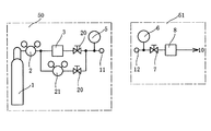
図1は、本実施形態の発明に係るガスリーク検査装置の構成を示す図。図2はガスリーク検査装置に適用される被検査対象物の構成の一例を示す図ある。
これらの図において、入口ガス定量供給装置50は、ガスボンベ1、減圧弁2、質量流量型流量制御装置3、圧力計5、ガス供給口11によって構成され、出口ガス流量計測装置51はガス導入口12、圧力計6、加圧制御装置7、質量流量型流量計8、排気ライン10によって構成される。また、被検査対象物54は被検査対象物本体、バルブ61、圧力計62等で構成される。
これらの図に示すように、図1に示すガスリーク検査装置の入口ガス定量供給装置50のガス供給接続口11は、図2に示す被検査対象物54である被測定対象ラインガス入口25に接続されてガスが供給され、被検査対象物54の被測定対象ラインガス出口26は、図1に示す流量測定装置接続口12に接続され、出口ガス流量計測装置51の質量流量型流量計8を通過したガス量を測定することによってガスリークが測定される。
ここで、 入口ガス定量供給装置50は、図2に示す被検査対象物54に測定中常に一定値のガスを安定供給するのみであり、出口ガス流量計測装置51に設けた加圧装置7を使用して、被検査対象物54である被検査対象ライン(被検査配管)の内圧を変え、印加圧力値(圧力計6)に対するそのときの質量流量型流量計8のガス流量を測定する。
An embodiment of the present invention will be described with reference to FIGS.
FIG. 1 is a diagram showing a configuration of a gas leak inspection apparatus according to the invention of this embodiment. FIG. 2 is a diagram illustrating an example of a configuration of an inspection target applied to the gas leak inspection apparatus.
In these drawings, an inlet gas fixed
As shown in these drawings, the gas
Here, the inlet gas fixed
このように、本実施形態のガスリーク検査装置においては、被検査対象物54からのガスリーク量が印加ガス圧力に比例して大きくなる現象に着目したものであり、出口ガス流量計測装置51側に加圧用の加圧制御装置7を設け、これによって圧力を2点以上変化させる。ガスリークが有る場合はその出口側の質量流量型流量計8のガス流量値に変化を生ずる。このように、入口側の流量は一定を保つているだけで出口側の流量の変化のみを測定してガスリークを検査することが可能となる。この原理を応用し出口側の一台の質量流量型流量計のみで、圧力に対する流量値の変化を測定し、その変化の傾きから安定して、高い精度でリークするガスを定量的に求めることができる。
この場合、質量流量型流量計8のカタログ値の精度としての相対精度(±0.2%)の範囲で測定できるので非常に高精度な測定を可能とする。絶対精度(±2%)を利用して測定する場合の10倍の精度を達成できる。
As described above, in the gas leak inspection apparatus according to the present embodiment, attention is paid to the phenomenon that the amount of gas leak from the
In this case, since the measurement can be performed within the range of the relative accuracy (± 0.2%) as the accuracy of the catalog value of the mass flow
図3は、被検査対象物54にリークのない場合の測定例を示す図であり、横軸は図1に示す出口ガス流量計測装置51の圧力計6によって計測された圧力値、縦軸は図1に示す出口ガス流量計測装置51の質量流量型流量計8によって計測されたガス流量値である。
同図に示すように、被検査対象物54にリークのない場合は、加圧制御装置7を使用して加圧した状態でも、質量流量型流量計8に減少を生じないのでガス圧力に対して流量の測定値が一定値であることを示す。
FIG. 3 is a diagram showing a measurement example in the case where there is no leak in the
As shown in the figure, when there is no leak in the inspected
図4は被検査対象物54に多少リークのある場合の測定例を示す図であり、出口ガス流量計測装置51の加圧制御装置7の圧力を上昇していくと、質量流量型流量計8の流量の測定値が減少してゆく。この例から解るように圧力を上昇させて流量値が減少するか否かを検出することにより、リークが有るか無いか検出できる。より高気密の検査をする場合は流量計のレンジが小さいものを使用すればその機器の検出限界(再現性の範囲)まで使用できる。
FIG. 4 is a diagram showing a measurement example in the case where there is a slight leak in the
このように、本発明のガスリーク検査装置は、ガス被検査対象物54における圧力計6において計測されたあるガス圧力に対する質量流量型流量計8において計測されたガス流量と、被検査対象物54における圧力計6において計測された他のあるガス圧力に対する質量流量型流量計8において計測されたガス流量とを求め、前記検出された両ガス圧力の差に対する両ガス流量との差との比(勾配)を求め、この比(勾配)から被検査対象物のガスリーク量を定量的に求めるものである。
As described above, the gas leak inspection apparatus of the present invention is configured so that the gas flow rate measured by the mass flow
図5は、図1に示したガスリーク検査装置の入口ガス定量供給装置50と異なる入口ガス定量供給装置50の構成を示す図であり、質量流量型流量制御装置3と直列に切換バルブ20を設けるともに、質量流量型流量制御装置3と切換バルブ20との直列体と並列に補助回路用減圧弁21と切換バルブ20との直列体を接続したものであり、補助回路用減圧弁21を用いることによって、測定圧近傍まで、ガスを別回路から供給し、待ち時間を短縮し、能率向上を図ろうとするものである。
このように構成することにより、配管容量の大きい場合に、微少リーク量の範囲で計測したい場合、供給流量を増加し、定常状態に達するまでの時間を短くして、計測時間の短縮化を図ることができる。
FIG. 5 is a diagram showing a configuration of an inlet gas
By configuring in this way, when the pipe capacity is large, if you want to measure in the range of minute leak amount, increase the supply flow rate, shorten the time to reach steady state, and shorten the measurement time be able to.
図6は、図1に示したガスリーク検査装置の入口ガス定量供給装置50及び出口ガス流量計測装置51と異なる入口ガス定量供給装置50及び出口ガス流量計測装置51の構成を示す図であり、入口ガス定量供給装置50において、質量流量型流量制御装置3と直列に切換バルブ20を設け、さらに質量流量型流量制御装置3と切換バルブ20との直列体と並列に質量流量型流量制御装置4と切換バルブ20との直列体を接続し、出口ガス流量計測装置51において、切換バルブ20と直列に質量流量型流量計8を設け、さらに切換バルブ20と質量流量型流量計8の直列体と並列に切換バルブ20と質量流量型流量計9との直列体を接続したものである。
FIG. 6 is a diagram showing the configuration of an inlet gas fixed
このように構成することにより、大〜小流量をより容易に測定することが可能となり、流量計を複数(2台以上)用いて、リーク量が大きい場合から小さい場合まで種々の状況に対応出来る使いやすい構造とすることができる。
最初の段階では大きなリークも予想され、その場合は大きな流量計を使用して測定し、後に小流量レンジに切り換えて、微少量の検査へと段階的に実施できる構造としたものである。異なるレンジのものを揃えて、だんだん小さくしてゆくことによって、一台の装置で広範囲に対応することができると同時に、より容易に使用することができる。
By configuring in this way, it becomes possible to easily measure a large to small flow rate, and a plurality of flow meters (two or more) can be used to cope with various situations from a large leak amount to a small leak amount. Easy to use structure.
In the first stage, a large leak is also expected. In such a case, the measurement is performed using a large flow meter, and the structure is such that a small flow rate range can be measured later and a small amount of inspection can be carried out step by step. By arranging different ranges and making them smaller, it is possible to handle a wide range with a single device, and at the same time, it can be used more easily.
1 ガスボンベ
2 減圧弁
3,4 質量流量型流量制御装置
5,6 圧力計
7 加圧制御装置
8,9 質量流量型流量計
10 排気
11 ガス供給接続口
12 流量測定装置接続口
20 切換バルブ
21 補助回路用減圧弁
25 被測定対象ラインガス入口
26 被測定対象ラインガス出口
50 入口ガス定量供給装置
51 出口ガス流量計測装置
54 被検査対象物(通過型)
61 バルブ
62 圧力計
1 Gas cylinder
2 Reducing
5,6 Pressure gauge
7 Pressure controller
8,9 Mass flow type flow meter
10 exhaust
11 Gas supply connection port
12 Flowmeter connection port
20
61
Claims (1)
An object to be inspected consisting of piping, an airtight container, etc., a gas metering supply device for supplying a certain amount of gas to the object to be inspected, a gas pressure control device for controlling the gas pressure in the object to be inspected, A flow meter for measuring the amount of gas discharged from the object to be inspected, and measuring a gas flow rate in the flow meter for a certain gas pressure in the object to be inspected, and other in the object to be inspected Measuring a gas flow rate in the flow meter for a certain gas pressure, and obtaining a gas leak amount of an object to be inspected during an airtight inspection from a ratio of the difference in the gas flow meter to a difference in the measured gas pressure Characteristic gas leak inspection device.
Priority Applications (1)
| Application Number | Priority Date | Filing Date | Title |
|---|---|---|---|
| JP2004267997A JP4281001B2 (en) | 2004-09-15 | 2004-09-15 | Gas leak inspection device |
Applications Claiming Priority (1)
| Application Number | Priority Date | Filing Date | Title |
|---|---|---|---|
| JP2004267997A JP4281001B2 (en) | 2004-09-15 | 2004-09-15 | Gas leak inspection device |
Publications (2)
| Publication Number | Publication Date |
|---|---|
| JP2006084263A true JP2006084263A (en) | 2006-03-30 |
| JP4281001B2 JP4281001B2 (en) | 2009-06-17 |
Family
ID=36162896
Family Applications (1)
| Application Number | Title | Priority Date | Filing Date |
|---|---|---|---|
| JP2004267997A Active JP4281001B2 (en) | 2004-09-15 | 2004-09-15 | Gas leak inspection device |
Country Status (1)
| Country | Link |
|---|---|
| JP (1) | JP4281001B2 (en) |
Cited By (3)
| Publication number | Priority date | Publication date | Assignee | Title |
|---|---|---|---|---|
| CN102928181A (en) * | 2012-10-31 | 2013-02-13 | 中国石油化工股份有限公司 | Simulation system for inner leak detection of hydrocarbon valve |
| US10656050B2 (en) | 2015-01-09 | 2020-05-19 | Avl Test Systems, Inc. | System and method for detecting a leak in an exhaust gas sampling apparatus |
| US10852211B2 (en) * | 2018-04-24 | 2020-12-01 | Korea Institute Of Energy Research | Apparatus and method for gas leakage measurement in a high pressure reactor |
-
2004
- 2004-09-15 JP JP2004267997A patent/JP4281001B2/en active Active
Cited By (3)
| Publication number | Priority date | Publication date | Assignee | Title |
|---|---|---|---|---|
| CN102928181A (en) * | 2012-10-31 | 2013-02-13 | 中国石油化工股份有限公司 | Simulation system for inner leak detection of hydrocarbon valve |
| US10656050B2 (en) | 2015-01-09 | 2020-05-19 | Avl Test Systems, Inc. | System and method for detecting a leak in an exhaust gas sampling apparatus |
| US10852211B2 (en) * | 2018-04-24 | 2020-12-01 | Korea Institute Of Energy Research | Apparatus and method for gas leakage measurement in a high pressure reactor |
Also Published As
| Publication number | Publication date |
|---|---|
| JP4281001B2 (en) | 2009-06-17 |
Similar Documents
| Publication | Publication Date | Title |
|---|---|---|
| JP4684135B2 (en) | Leakage inspection method and leak inspection apparatus for piping | |
| JP6636044B2 (en) | Leak inspection apparatus and method | |
| CN107941307B (en) | Propellant flow field calibration system and method for conventional large-scale liquid engine | |
| US9429493B2 (en) | Manifold assembly for a portable leak tester | |
| CN103822765A (en) | Device for detecting air leakage rate of large-scale ventilating device | |
| JP5620184B2 (en) | Leak inspection apparatus and leak inspection method | |
| JP2010054512A (en) | Process connection adapter for meter calibration system | |
| JP5049199B2 (en) | External pressure detection type leak inspection device and leak inspection method using the same | |
| US10317307B2 (en) | Large volume test apparatuses and methods for detection of small defects | |
| JP2009092585A (en) | Leak detector | |
| KR101129659B1 (en) | Flowmeter check apparatus having portable checking device for flowmeter and method to check flow measurement system using the same | |
| JP2006275906A (en) | Leakage inspection method and system | |
| JP4281001B2 (en) | Gas leak inspection device | |
| CN108088883A (en) | For checking the detection device of gas induction element | |
| JPH10185749A (en) | Method and apparatus for leak inspection | |
| CN203772508U (en) | Large-scale ventilating device air leakage rate detector | |
| KR102008889B1 (en) | Gas Meter Performance Tester | |
| KR101909903B1 (en) | System for testing airtightness of gasket | |
| CN104502039A (en) | Gas tightness detecting method for fuel gas meter | |
| JP2001066216A (en) | Instrument and method for measuring quantity of leakage from gasket | |
| JPH1137883A (en) | Method for measuring leak amount | |
| JP5739212B2 (en) | Piping airtightness inspection method and piping airtightness inspection device | |
| CN209446237U (en) | The water plate tightness test system of dish-washing machine | |
| CN114076660B (en) | Pipeline leakage point positioning detection device and method for closed space | |
| KR20180057391A (en) | Continuous pressure leak test device module |
Legal Events
| Date | Code | Title | Description |
|---|---|---|---|
| A621 | Written request for application examination |
Free format text: JAPANESE INTERMEDIATE CODE: A621 Effective date: 20070129 |
|
| A977 | Report on retrieval |
Free format text: JAPANESE INTERMEDIATE CODE: A971007 Effective date: 20081113 |
|
| A131 | Notification of reasons for refusal |
Free format text: JAPANESE INTERMEDIATE CODE: A131 Effective date: 20081118 |
|
| A521 | Request for written amendment filed |
Free format text: JAPANESE INTERMEDIATE CODE: A523 Effective date: 20081218 |
|
| TRDD | Decision of grant or rejection written | ||
| A01 | Written decision to grant a patent or to grant a registration (utility model) |
Free format text: JAPANESE INTERMEDIATE CODE: A01 Effective date: 20090303 |
|
| A01 | Written decision to grant a patent or to grant a registration (utility model) |
Free format text: JAPANESE INTERMEDIATE CODE: A01 |
|
| A61 | First payment of annual fees (during grant procedure) |
Free format text: JAPANESE INTERMEDIATE CODE: A61 Effective date: 20090304 |
|
| R150 | Certificate of patent or registration of utility model |
Ref document number: 4281001 Country of ref document: JP Free format text: JAPANESE INTERMEDIATE CODE: R150 Free format text: JAPANESE INTERMEDIATE CODE: R150 |
|
| FPAY | Renewal fee payment (event date is renewal date of database) |
Free format text: PAYMENT UNTIL: 20120327 Year of fee payment: 3 |
|
| FPAY | Renewal fee payment (event date is renewal date of database) |
Free format text: PAYMENT UNTIL: 20120327 Year of fee payment: 3 |
|
| FPAY | Renewal fee payment (event date is renewal date of database) |
Free format text: PAYMENT UNTIL: 20120327 Year of fee payment: 3 |
|
| FPAY | Renewal fee payment (event date is renewal date of database) |
Free format text: PAYMENT UNTIL: 20130327 Year of fee payment: 4 |
|
| R250 | Receipt of annual fees |
Free format text: JAPANESE INTERMEDIATE CODE: R250 |
|
| FPAY | Renewal fee payment (event date is renewal date of database) |
Free format text: PAYMENT UNTIL: 20130327 Year of fee payment: 4 |
|
| FPAY | Renewal fee payment (event date is renewal date of database) |
Free format text: PAYMENT UNTIL: 20130327 Year of fee payment: 4 |
|
| FPAY | Renewal fee payment (event date is renewal date of database) |
Free format text: PAYMENT UNTIL: 20140327 Year of fee payment: 5 |
|
| R250 | Receipt of annual fees |
Free format text: JAPANESE INTERMEDIATE CODE: R250 |
|
| FPAY | Renewal fee payment (event date is renewal date of database) |
Free format text: PAYMENT UNTIL: 20140327 Year of fee payment: 5 |
|
| R250 | Receipt of annual fees |
Free format text: JAPANESE INTERMEDIATE CODE: R250 |
|
| S111 | Request for change of ownership or part of ownership |
Free format text: JAPANESE INTERMEDIATE CODE: R313113 |
|
| R360 | Written notification for declining of transfer of rights |
Free format text: JAPANESE INTERMEDIATE CODE: R360 |
|
| R360 | Written notification for declining of transfer of rights |
Free format text: JAPANESE INTERMEDIATE CODE: R360 |
|
| R371 | Transfer withdrawn |
Free format text: JAPANESE INTERMEDIATE CODE: R371 |
|
| S111 | Request for change of ownership or part of ownership |
Free format text: JAPANESE INTERMEDIATE CODE: R313113 |
|
| R350 | Written notification of registration of transfer |
Free format text: JAPANESE INTERMEDIATE CODE: R350 |
|
| R250 | Receipt of annual fees |
Free format text: JAPANESE INTERMEDIATE CODE: R250 |
|
| R250 | Receipt of annual fees |
Free format text: JAPANESE INTERMEDIATE CODE: R250 |
|
| R250 | Receipt of annual fees |
Free format text: JAPANESE INTERMEDIATE CODE: R250 |
|
| R250 | Receipt of annual fees |
Free format text: JAPANESE INTERMEDIATE CODE: R250 |
|
| R250 | Receipt of annual fees |
Free format text: JAPANESE INTERMEDIATE CODE: R250 |
|
| R250 | Receipt of annual fees |
Free format text: JAPANESE INTERMEDIATE CODE: R250 |
|
| R250 | Receipt of annual fees |
Free format text: JAPANESE INTERMEDIATE CODE: R250 |
|
| R250 | Receipt of annual fees |
Free format text: JAPANESE INTERMEDIATE CODE: R250 |
|
| R250 | Receipt of annual fees |
Free format text: JAPANESE INTERMEDIATE CODE: R250 |
|
| R250 | Receipt of annual fees |
Free format text: JAPANESE INTERMEDIATE CODE: R250 |