JP2006081925A - Hand-drying apparatus - Google Patents
Hand-drying apparatus Download PDFInfo
- Publication number
- JP2006081925A JP2006081925A JP2005327826A JP2005327826A JP2006081925A JP 2006081925 A JP2006081925 A JP 2006081925A JP 2005327826 A JP2005327826 A JP 2005327826A JP 2005327826 A JP2005327826 A JP 2005327826A JP 2006081925 A JP2006081925 A JP 2006081925A
- Authority
- JP
- Japan
- Prior art keywords
- air
- fan motor
- housing
- palm
- hand
- Prior art date
- Legal status (The legal status is an assumption and is not a legal conclusion. Google has not performed a legal analysis and makes no representation as to the accuracy of the status listed.)
- Granted
Links
Images


Abstract
Description
本発明は、手乾燥装置に係り、特に、洗浄後の濡れた手を所定位置に配置すると、手の甲側及び掌側に自動的に風を送って乾燥させる手乾燥装置に関する。 The present invention relates to a hand drying device, and more particularly to a hand drying device that automatically sends wind to the back side and palm side of the hand when the wet hand after washing is placed at a predetermined position.
従来から、洗浄後の濡れた手を所定位置に配置すると、手の甲側及び掌側に自動的に風を送って乾燥させる手乾燥装置の代表的なものとしては、例えば、特許文献1に記載されたタイプのものが知られている。
この従来の手乾燥装置においては、手乾燥装置の全体を構成するハウジング内の下部に、鉛直方向に延びる回転軸を有する2台のファンモータがほぼ真横に並べて配置されており、ハウジングの上部には、濡れた手が上方から挿入されて配置される手挿入配置スペースが形成されている。
Conventionally, a typical example of a hand drying device that automatically sends wind to the back side and palm side of the hand when the wet hand after washing is placed at a predetermined position is described in
In this conventional hand drying apparatus, two fan motors having a rotating shaft extending in the vertical direction are arranged substantially side by side at the lower part in the housing constituting the whole hand drying apparatus, A hand insertion arrangement space is formed in which wet hands are inserted and arranged from above.
また、ハウジングの上部の手挿入配置スペースに面している部分には、手挿入配置スペース内の所定位置に配置した手の甲側及び掌側のそれぞれに向けて風が吹き出される甲側用吹出ノズルと掌側用吹出ノズルがそれぞれ設けられている。
各吹出ノズルは、別々の吹出ダクトを経て各ファンモータと連通している。手挿入配置スペース内に手を配置すると、センサがそれを検知して各ファンモータが作動するようになっている。ファンモータが作動すると、ファンモータの背面下方にある空気取入口から吸気ダクトを経て各ファンモータの吸込口に空気が吸込まれ、各ファンモータから独立に各吹出ノズルに送られた風が、手の甲側及び掌側のそれぞれに向けて吹き出されるようになっている。
In addition, in the portion facing the hand insertion arrangement space at the upper part of the housing, the upper side blowing nozzle for blowing wind toward the back side and palm side of the hand arranged at a predetermined position in the hand insertion arrangement space And a palm-side blowing nozzle.
Each blowing nozzle communicates with each fan motor via a separate blowing duct. When a hand is placed in the manual insertion space, the sensor detects this and each fan motor is activated. When the fan motor is activated, air is sucked into the suction port of each fan motor from the air intake port below the back of the fan motor through the intake duct, and the wind sent from each fan motor to each blowing nozzle independently It blows out toward each of the side and the palm side.
このような従来の手乾燥装置では、各ファンモータの出力を調整して、手の甲側及び掌側に供給する風量の比率を変えることができるため、手の甲側及び掌側のそれぞれにおいて効率的な乾燥が行われる。 In such a conventional hand drying device, the output of each fan motor can be adjusted to change the ratio of the air volume supplied to the back side and palm side of the hand. Is done.
しかしながら、従来の手乾燥装置においては、一般的に手の甲側と掌側で同一の風量で乾燥させた場合、掌側の方が乾燥しにくいことが知られており、掌側に供給する風量が手の甲側に供給する風量に比べて大きくなるように、掌側用のファンモータの回転を甲側用のファンモータの回転に比べて高速に設定したりしている。
さらに、従来の手乾燥装置では、ファンモータの背面下方にある空気取入口から各ファンモータの吸込口までの吸気ダクトの距離が共に等しいため、特に、より高速に回転している掌側用のファンモータで発生した大きな騒音の方が空気取入口等から漏出するという問題がある。
However, in the conventional hand drying device, it is generally known that when the back side and the palm side of the hand are dried with the same air volume, the palm side is less likely to dry. The rotation of the fan motor for the palm side is set at a higher speed than the rotation of the fan motor for the back side so that the amount of air supplied to the back side of the hand becomes larger.
Furthermore, in the conventional hand dryer, since the distance of the intake duct from the air intake port below the back of the fan motor to the intake port of each fan motor is equal, especially for the palm side rotating at a higher speed. There is a problem that the loud noise generated by the fan motor leaks out of the air intake.
また、従来の手乾燥装置においては、各ファンモータから甲側用吹出ノズル及び掌側用吹出ノズルまでの各吹出ダクトについては、同様な形態となっているため、高回転に設定した方のファンモータにおける風量が大きい吹出ダクトでは風路抵抗が大きくなり、ファンモータの所要動力が大きくなるという問題がある。 Further, in the conventional hand drying apparatus, each blowing duct from each fan motor to the upper side blowing nozzle and the palm side blowing nozzle has the same form, so the fan set to high rotation is used. A blowout duct having a large air volume in the motor has a problem that the air path resistance increases and the required power of the fan motor increases.
そこで、本発明は、上述した従来技術の問題を解決するためになされたものであり、所定位置に配置された洗浄後の濡れた手に風を送るためのファンモータにおける所要動力を低減させると共に、運転時の低騒音化を実現する手乾燥装置を提供することを目的としている。 Accordingly, the present invention has been made to solve the above-described problems of the prior art, and reduces the required power in a fan motor for sending wind to a wet hand after cleaning arranged at a predetermined position. An object of the present invention is to provide a hand-drying device that achieves low noise during operation.
上記の目的を達成するために、本発明は、使用者の手の甲と掌の両側に空気を吹き付けて乾燥させる手乾燥装置であって、使用者の手が挿入される手乾燥部となる上方に開口した開口凹部をその上端部に形成したハウジングと、ハウジングの下方部分に設けられた空気取入口と、開口凹部を形成するハウジングの甲側内壁面に設けられ手乾燥部に空気を吹出す第1空気吹出部と、開口凹部を形成するハウジングの掌側内壁面に設けられ手乾燥部に空気を吹き出す第2空気吹出部と、ハウジング内に設けられ、このハウジングの前後方向で水平方向に延びる第1駆動軸、この第1駆動軸の後方側に位置し空気を吸い込む第1空気吸込口、第1駆動軸の前方側に位置し空気を吹出す第1空気吹出口を備えた第1ファンモータ手段と、ハウジング内に設けられ、このハウジングの前後方向で水平方向に延びる第2駆動軸、この第2駆動軸の後方側に位置し空気を吸い込む第2空気吸込口、第2駆動軸の前方側に位置し空気を吹出す第2空気吹出口を備えた第2ファンモータ手段と、空気取入口から第1ファンモータ手段の第1空気吸込口まで延びる第1吸気ダクトと、空気取入口から第2ファンモータ手段の第2空気吸込口まで延びる第2吸気ダクトと、第1ファンモータ手段の第1空気吹出口から第1空気吹出部まで延びる第1吹出ダクトと、第2ファンモータ手段の第2空気吹出口から第2空気吹出部まで延びる第2吹出ダクトと、を有し、第1吸気ダクトは、空気取入口から第1ファンモータ手段の第1空気吸込口までハウジングの後方側内壁面に沿って延び、第2吸気ダクトは、空気取入口から第2ファンモータ手段の第2空気吸込口までハウジングの後方側内壁面に沿って延び、第1吹出ダクトは、第1ファンモータ手段の第1空気吹出口からハウジングの後方側内壁面に向って斜め上方に延び、さらに、開口凹部の甲側内壁面の裏面に沿って第1空気吹出部まで延び、第2吹出ダクトは、第2ファンモータ手段の第2空気吹出口からハウジングの前方側内壁面及び開口凹部の掌側内壁面の裏面に沿って第2空気吹出部まで延び、第2空気吹出部は、第2空気吹出口のほぼ真上に位置していることを特徴としている。 In order to achieve the above object, the present invention is a hand drying device that blows air on both sides of the back and palm of a user to dry the hand, and is provided above a hand drying unit into which the user's hand is inserted. A housing in which an open recess is formed at the upper end, an air intake port provided in a lower portion of the housing, and a first air blower that blows air to a hand drying unit provided on the inner wall of the upper side of the housing that forms the open recess. 1 air blowing portion, a second air blowing portion that is provided on the palm side inner wall surface of the housing forming the opening recess and blows air to the hand drying portion, and is provided in the housing and extends in the horizontal direction in the front-rear direction of the housing. A first fan having a first drive shaft, a first air suction port that is located on the rear side of the first drive shaft and sucks air, and a first air outlet that is located on the front side of the first drive shaft and blows out air Motor means and in the housing A second drive shaft that extends horizontally in the front-rear direction of the housing, a second air suction port that is located on the rear side of the second drive shaft and sucks air, and is located on the front side of the second drive shaft. A second fan motor means having a second air outlet for blowing out, a first intake duct extending from the air intake port to the first air intake port of the first fan motor means, and the second fan motor means from the air intake port. From the second air intake duct extending to the second air inlet, the first air outlet duct extending from the first air outlet of the first fan motor means to the first air outlet, and the second air outlet of the second fan motor means A second air outlet duct extending to the second air outlet, the first air intake duct extending along the rear inner wall surface of the housing from the air intake port to the first air inlet port of the first fan motor means, The second intake duct is The first air duct extends from the air inlet to the second air suction port of the second fan motor means along the rear inner wall surface of the housing, and the first blow-out duct extends from the first air outlet of the first fan motor means to the rear side of the housing. It extends obliquely upward toward the wall surface, further extends along the back surface of the inner wall surface on the back side of the opening recess to the first air blowing portion, and the second blowing duct extends from the second air blowing port of the second fan motor means to the housing. The front side inner wall surface and the back side of the palm-side inner wall surface of the opening recess extend to the second air blowing portion, and the second air blowing portion is positioned almost directly above the second air blowing port. It is said.
このように構成された本発明においては、ハウジングの手乾燥部内に手を配置すると、第1及び第2ファンモータ手段が作動する。つぎに、空気取入口から第1及び第2吸気ダクトへ空気が取り込まれ、これらの空気は、第1及び第2吸気ダクトから第1及び第2ファンモータ手段の第1及び第2空気吸込口にそれぞれ吸込まれる。さらに、空気は、第1及び第2ファンモータ手段の第1及び第2空気吹出口から第1及び第2吹出ダクトにそれぞれ吹き出され、最終的には、第1及び第2空気吹出部から手乾燥部の内方へ吹き出される。 In the present invention configured as described above, the first and second fan motor means operate when a hand is placed in the hand drying section of the housing. Next, air is taken into the first and second intake ducts from the air intake, and these air are supplied from the first and second intake ducts to the first and second air intake ports of the first and second fan motor means. Each is inhaled. Further, air is blown out from the first and second air outlets of the first and second fan motor means to the first and second outlet ducts, respectively, and finally from the first and second air outlets. It blows out inward of the drying section.
本発明によれば、第2ファンモータ手段が第1ファンモータ手段の上方に配置されているため、第2ファンモータ手段における所要動力を低減させると共に、手乾燥装置の運転時における低騒音化を実現することができる。
本発明によれば、第1吸気ダクトが、空気取入口から第1ファンモータ手段の第1空気吸込口までハウジングの後方側内壁面に沿って延び、第2吸気ダクトが、空気取入口から第2ファンモータ手段の第2空気吸込口までハウジングの後方側内壁面に沿って延びるので、第1及び第2ファンモータ手段の作動音が空気取入口から漏れにくくなり、手乾燥装置の運転時における低騒音化を実現することができる。
According to the present invention, since the second fan motor means is disposed above the first fan motor means, the required power in the second fan motor means is reduced and the noise during operation of the hand dryer is reduced. Can be realized.
According to the present invention, the first air intake duct extends from the air intake port to the first air intake port of the first fan motor means along the rear inner wall surface of the housing, and the second air intake duct extends from the air intake port to the first air intake port. Since the two fan motor means extend along the rear inner wall surface of the housing to the second air suction port, the operating sound of the first and second fan motor means is less likely to leak from the air intake, and the hand dryer is in operation. Low noise can be achieved.
本発明によれば、第1吹出ダクトが、第1ファンモータ手段の第1空気吹出口からハウジングの後方側内壁面に向って斜め上方に延び、さらに、開口凹部の甲側内壁面の裏面に沿って第1空気吹出部まで延び、第2吹出ダクトが、第2ファンモータ手段の第2空気吹出口からハウジングの前方側内壁面及び開口凹部の掌側内壁面の裏面に沿って第2空気吹出部まで延びているので、第2吹出ダクト内の風路抵抗の増加を抑制し、第2ファンモータにおける所要動力の増大を低減させることができる。
本発明によれば、第2空気吹出部が、第2空気吹出口のほぼ真上に位置しているので、ことが好ましい。これにより、第2吹出ダクトの風路抵抗が小さくなるように設定することができ、第2ファンモータ手段における所要動力の増大を低減させることができる。
According to the present invention, the first outlet duct extends obliquely upward from the first air outlet of the first fan motor means toward the rear side inner wall surface of the housing, and further on the back surface of the inner side wall surface of the opening recess. The second air duct extends from the second air outlet of the second fan motor means to the front inner wall surface of the housing and the back surface of the palm inner wall surface of the opening recess. Since it extends to the blowing portion, it is possible to suppress an increase in air path resistance in the second blowing duct and to reduce an increase in required power in the second fan motor.
According to this invention, since the 2nd air blowing part is located substantially right above the 2nd air blowing outlet, it is preferable. Thereby, it can set so that the air path resistance of a 2nd blowing duct may become small, and the increase in the required power in a 2nd fan motor means can be reduced.
本発明の手乾燥装置によれば、所定位置に配置された洗浄後の濡れた手に風を送るためのファンモータにおける所要動力を低減させると共に運転時の低騒音化を実現することができる。 According to the hand drying device of the present invention, it is possible to reduce the required power in the fan motor for sending air to the wet hands after washing disposed at a predetermined position and to reduce noise during operation.
以下、添付図面を参照して本発明の手乾燥装置の実施形態について説明する。
図1は、本発明の一実施形態による手乾燥装置を示す正面図であり、図2は、本発明の一実施形態による手乾燥装置を示す背面図である。
また、図3は、本発明の一実施形態による手乾燥装置を示す平面図であり、図4は、本発明の一実施形態による手乾燥装置を示す底面図である。
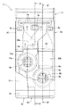
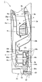
さらに、図5は、本発明の一実施形態による手乾燥装置を示す左側面図であり、図6は、図1に示す本発明の一実施形態による手乾燥装置のA−A断面図であり、図7は、図1に示す本発明の一実施形態による手乾燥装置のB−B断面図である。
なお、図1、図2、図6及び図7では、手乾燥装置内部の空気の流れを矢印で示している。
Hereinafter, an embodiment of a hand dryer according to the present invention will be described with reference to the accompanying drawings.
FIG. 1 is a front view showing a hand dryer according to an embodiment of the present invention, and FIG. 2 is a rear view showing the hand dryer according to an embodiment of the present invention.
FIG. 3 is a plan view showing a hand dryer according to an embodiment of the present invention, and FIG. 4 is a bottom view showing the hand dryer according to an embodiment of the present invention.
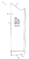
5 is a left side view showing a hand drying device according to an embodiment of the present invention, and FIG. 6 is a cross-sectional view of the hand drying device according to the embodiment of the present invention shown in FIG. FIG. 7 is a cross-sectional view of the hand dryer according to the embodiment of the present invention shown in FIG.
In FIG. 1, FIG. 2, FIG. 6 and FIG. 7, the flow of air inside the hand dryer is indicated by arrows.
図1〜図7に示すように、本実施形態の手乾燥装置1は、手乾燥装置本体を取り囲むハウジング2を備えている。このハウジング2の上部には、ハウジング2の上方からその内部へ並べた両手を挿入することができるように、上端が開口した上端開口凹部4が設けられている。
この上端開口凹部4は、そこに手を配置して風を当てて乾燥させる部分(手乾燥部)である。通常、掌をハウジング2の正面2a側に向け、手の甲をハウジング2の背面2b側に向けた姿勢で、手をハウジング2の上方から上端開口凹部(手乾燥部)4内へ挿入するようになっている。
As shown in FIGS. 1-7, the
This upper-end opening recessed part 4 is a part (hand drying part) which arrange | positions a hand there and applies wind and dries. Usually, the hand is inserted into the upper end opening recess (hand drying portion) 4 from above the
なお、以下、説明の便宜上、本実施形態の手乾燥装置1を構成する部分(要素)において、手乾燥部4内に配置した手の掌側を乾燥させるための関連要素の各名称には「掌側」と付し、手の甲側を乾燥させるための関連部分の各名称には「甲側」と付することにする。
また、本実施形態の手乾燥装置1では、手をハウジング2の上方から上端開口凹部(手乾燥部)4内へ挿入し、上端開口凹部(手乾燥部)4の掌側内壁面4a及び甲側内壁面4bにそれぞれ設けられたセンサ3a,3bが手を検知すると、両内壁面4a,4bにそれぞれ設けられた複数の掌側用ノズル6a及び甲側用ノズル6bから、手の掌側及び甲側にそれぞれ温風が吹き付けられるようになっている。
Hereinafter, for convenience of explanation, in the part (element) constituting the
Further, in the
さらに、図3に示すように、ハウジング2の各寸法については、成人の両手を並べて上端開口凹部(手乾燥部)4内へ挿入した際に、掌と手の甲が、上端開口凹部(手乾燥部)4の掌側内壁面4a及び甲側内壁面4bのそれぞれと接触しないように寸法決めされている。
例えば、ハウジング2の横幅wについては、好ましくは200mm〜350mmであり、最も好ましくは300mmである。
また、ハウジングの奥行d1は、好ましくは120mm〜250mmであり、最も好ましくは180mm〜200mmである。
Further, as shown in FIG. 3, for each dimension of the
For example, the lateral width w of the
The depth d1 of the housing is preferably 120 mm to 250 mm, and most preferably 180 mm to 200 mm.
さらに、掌側用ノズル6aと甲側用ノズル6bとの距離d2については、好ましくは70mm〜100mmであり、最も好ましくは85mmである。なお、成人男性の手の幅は、平均的には約80mmであって、これ以上の間隔であれば手の向きを変える際にも壁面に接触しないで済む。
また、ハウジング2の高さは、好ましくは450mm〜700mmであり、最も好ましくは680mmである。
Furthermore, the distance d2 between the palm-
The height of the
さらに、ハウジング2の両側面2c,2dには、風抜き手段であるルーバー5が設けられ(図5参照)、手乾燥部4内に配置された手にノズル6a,6bから温風が吹きつけられた際にハウジング2の側面2c,2dの方向に飛散した水滴が、このルーバー5により遮断され、風のみがルーバー5を抜けるようになっている。
Furthermore,
また、ハウジング2内には、掌側用及び甲側用ノズル6a,6bのそれぞれに送風するための掌側用及び甲側用ファンモータユニット8a,8bが互いに隣接して設けられている。
各ファンモータユニット8a,8bは、その回転駆動軸10a,10bがハウジング2の正面2a及び又は背面2bに対して垂直な方向に延びるように配置されている(図6及び図7参照)。
Also, in the
Each
なお、掌側用及び甲側用ファンモータユニット8a,8bとも同一の最大出力を有する同一形態のものであり、両者とも所望に回転駆動軸10a,10bの回転数を変えることができるようになっている。手乾燥装置1の使用時には、掌側用回転駆動軸10aが甲側用回転駆動軸10bよりも高速に回転するように各ファンモータユニット8a,8bを設定し、掌側に供給する風量が手の甲側に供給する風量に比べて大きくするのが好ましい。
また、甲側用ファンモータユニット8bは、ハウジング2の底部に隣接して配置され、掌側用ファンモータユニット8aは、その掌側用回転駆動軸10aが甲側用回転駆動軸10bに対して前方斜め上方に位置するように、甲側用ファンモータユニット8bの前方斜め上方に隣接して配置されている(図1、図6及び図7参照)。
Note that the palm-side and upper-side
Further, the upper
さらに、各ファンモータユニット8a,8bの各ケーシング12a,12bの後端部には、掌側用及び甲側用空気吸込口14a,14bがそれぞれ設けられている。
一方、各ファンモータユニット8a,8bの上方に突出する各吹出ダクト15a,15bの下流端には、掌側用及び甲側用空気吹出口16a,16bがそれぞれ形成されている。この各吹出口16a,16bには、掌側用及び甲側用フィンヒータ18a,18bがそれぞれ設けられ、各フィンヒータ18a,18bにより、各吹出口16a,16bから吹き出される空気が温められるようになっている。
Further, palm-side and upper-
On the other hand, palm-side and upper-
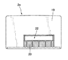
また、ハウジング2の底部2eには水受けトレー19が設けられており、手乾燥部4内において両端がなで肩形状の底面4cに落ちて両側に掃けた水が、ハウジング2の両側端にある排水溝(図示せず)を伝って水受けトレー19内に落ちるようになっている。
さらに、水受けトレー19の背面側には、フィルタ20を備えた空気取入口22が設けられ、この空気取入口22には、掌側用及び甲側用吸気ダクト24a,24bがそれぞれ接続されている。各吸気ダクト24a,24bは、それらの上流端26a,26bが空気取入口22のフィルタ20の上に配置され、各上流端26a,26bと各吸込口14a,14bを連通させるように、各上流端26a,26bからハウジング2の背面2b(ハウジングの背面側内壁面)に沿って上方にほぼ真っ直ぐ延びている(図2、図6及び図7参照)。
手乾燥装置1の作動中、ハウジング2の外部の空気は、空気取入口22からフィルタ20を介して、各吸気ダクト24a,24bに別々に吸込まれるようになっている。
Further, a
Further, an
During the operation of the
さらに、各吸気ダクト24a,24bは、その上端部が各ファンモータユニット8a,8bの上端部の高さとほぼ等しく、各ファンモータユニット8a,8bの背面全体を覆うように形成されている。
また、上述したように、掌側用ファンモータユニット8aを甲側用ファンモータユニット8bの前方斜め上方に隣接して配置したことに伴って、掌側用空気吸込口14aも甲側用空気吸込口14bに対して前方斜め上方に位置するため、掌側用吸気ダクト24aの上流端26aから掌側用空気吸込口14aまでの掌側用吸気ダクト24aの経路は、甲側用吸気ダクト24bの上流端26bから甲側用空気吸込口14bまでの甲側用吸気ダクト24bの経路よりも長くなっている。
Further, the
In addition, as described above, the palm-side
さらに、掌側用空気吸込口14aが甲側用空気吸込口14bよりも前方に位置するため、掌側用吸気ダクト24a内のスペースについては、その奥行き寸法が甲側用吸気ダクト24bの奥行き寸法よりも大きくなるように確保されており、掌側用吸気ダクト24aの平均断面積が甲側用吸気ダクト24bの平均断面積よりも大きく設定されている。
Further, since the palm-side
さらに、掌側用吸気ダクト24a及び甲側用吸気ダクト24b内の各上部において、各ファンモータユニット8a,8bの各吸込口14a,14bに隣接して掌側用吸音材28a及び甲側用吸音材28bがそれぞれ配置されており、各吸音材28a,28bにより、各ファンモータユニット8a,8bの作動中に各吸込口14a,14bから漏出した音がそれぞれ吸収されるようになっている。
さらに、各吸気ダクト24a,24b(吸音材28a,28b)の上端部の高さ位置は、上述した各ファンモータユニット8a,8bの各吹出口16a,16bの高さ位置ともほぼ等しくなっており、掌側用空気吹出口16aは甲側用空気吹出口16bよりも高い位置に位置している(図6及び図7参照)。
Further, at each upper part in the palm
Furthermore, the height position of the upper end of each
さらに、掌側用空気吹出口16aには掌側用吹出ダクト30aが接続されており、この掌側用吹出ダクト30aは、ハウジング2の正面2a(ハウジング2の正面側内壁面)に隣接して吹出口16aから、このハウジング2の正面側内壁面に沿って上方に延びるように形成されている。
また、掌側用吹出ダクト30a内の背面は、上述した上端開口凹部(手乾燥部)4の掌側内壁面4aの裏面を形成しており、ダクト30a内の上部の背面側には、複数の掌側用ノズル6aが掌側用空気吹出口16aのほぼ真上に位置するように配置されている(図1及び図6参照)。
Further, a palm
Moreover, the back surface in the palm
さらに、甲側用空気吹出口16bには、掌側用空気吹出口16aと同様に、甲側用吹出ダクト30bが接続されている。この甲側用吹出ダクト30bは、甲側用空気吹出口16bから、上端開口凹部(手乾燥部)4の甲側内壁面4bに配置されている複数の甲側用ノズル6bへと開口凹部4の甲側内壁面4bの裏面に沿って延びるように形成されている。
より詳細には、甲側用吹出ダクト30bは、甲側用空気吹出口16bからほぼ真上に、掌側用ファンモータユニット8aの掌側用空気吸込口14aの高さ位置ぐらいまで延びた後、そこからハウジング2の背面2bにかけて斜め上方に、ほぼ上端開口凹部(手乾燥部)4の底面4cの高さ位置ぐらいまで延びるように形成されている(図7参照)。その後、吹出ダクト30bは、甲側用吹出ダクト30b内の正面が上端開口凹部(手乾燥部)4の甲側内壁面4bを形成するように上方に延びており、ダクト30b内の上部の正面側には、複数の甲側用ノズル6bが配置されている。
Further, the upper
More specifically, after the upper side
また、甲側用空気吹出口16bから甲側用ノズル6bまでの甲側用吹出ダクト30bの経路は、掌側用空気吹出口16aから掌側用ノズル6aまでの掌側用吹出ダクト30aの経路よりも長くなっている。
なお、本実施形態においては、フィンヒータ18a,18bは必ずしも必要はなく、設置状況等により、任意に設定可能である。
Further, the path of the upper
In the present embodiment, the
つぎに、上述した本発明の一実施形態による手乾燥装置1の作用(動作)について説明する。
使用者が手乾燥装置1のハウジング2の手乾燥部4に上方から手を挿入すると、センサ3a,3bが手を検知し、掌側用ファンモータユニット8a及び甲側用ファンモータユニット8bが作動する。このとき、掌側用ファンモータユニット8aの回転駆動軸10aが甲側用ファンモータユニット8bの回転駆動軸10bよりも高速に回転している。
これらのファンモータユニット8a,8bの作動により、ハウジング2の空気取入口22からフィルタ20を介して掌側用吸気ダクト24a及び甲側用吸気ダクト24bのそれぞれに空気が取り込まれる。
これらの各吸気ダクト24a,24bに取り込まれた空気は、掌側用空気吸込口14a及び甲側用空気吸込口14bから各ファンモータユニット8a,8bの内部にそれぞれ吸込まれる。
Next, the operation (operation) of the
When the user inserts a hand into the hand drying section 4 of the
By the operation of these
The air taken into the
そして空気は、各ファンモータユニット8a,8bの各吹出口16a,16bで各フィンヒータ18a,18bにより温められて、各吹出ダクト30a,30bに吹き出される。各吹出ダクト30a,30b内の空気は各ノズル6a,6bへ送られ、掌側用ノズル6a及び甲側用ノズル6bから、手乾燥部4内の掌及び手の甲にそれぞれ温風が吹き付けられる。この際、掌側用ノズル6aから手の掌側に吹きつけられる風量は、甲側用ノズルから手の甲側に吹きつけられる風量よりも大きくなる。
And air is warmed by each
なお、本実施形態の手乾燥装置1においては、一例として、掌側用ノズル6aと甲側用ノズル6bとの距離を85mmに設定した場合、掌側用ノズル6aにおける風速は約100m/sであり、甲側用ノズル6bにおける風速は約90m/sであり、乾燥時間(両ファンモータユニット8a,8bの運転時間)は約5秒となる迅速な乾燥運転を実現することができた。
また、これらの風速を発生させるために、直径130mmのファンモータを内蔵するファンモータユニット(最大外形約160mm)を2個用いたが、各ファンモータユニットをずらして並べたのでスリム化でき、ハウジングの厚みも含めて、ハウジングの外形幅を300mmにすることができた。
In the
Moreover, in order to generate these wind speeds, two fan motor units (maximum outer diameter of about 160 mm) with a built-in fan motor with a diameter of 130 mm were used. Including the thickness of the housing, the outer width of the housing could be 300 mm.
上述した本発明の一実施形態による手乾燥装置1においては、掌側用ファンモータユニット8aを甲側用ファンモータユニット8bの前方斜め上方に隣接して配置したことにより、掌側用ファンモータユニット8aと甲側用ファンモータユニット8bを互いに真横に並置させた場合よりもハウジング2の横幅wを小さく設定することができる。この結果、各ファンモータユニット8a,8bの動力を維持しつつ手乾燥装置1の全体をスリム化することができる。
In the
また、本実施形態による手乾燥装置1によれば、掌側用ファンモータユニット8aを甲側用ファンモータユニット8bの前方斜め上方に隣接して配置したことにより、掌側用吸気ダクト24aの上流端26aから掌側用空気吸込口14aまでの掌側用吸気ダクト24aの経路は、甲側用吸気ダクト24bの上流端26bから甲側用空気吸込口14bまでの甲側用吸気ダクト24bの経路よりも長くなっている。この結果、掌側用吸気ダクト24aの経路と甲側用吸気ダクト24bの経路が等しい場合に比べて、掌側用ファンモータユニット8aで生ずる作動音が掌側用空気吸込口14aから掌側用吸気ダクト24aを経て空気取入口22より漏れにくくなる。したがって、手乾燥装置1の全体の運転音を約63dbまで低減させることができる。
Further, according to the
さらに、本実施形態による手乾燥装置1によれば、掌側用ファンモータユニット8aを甲側用ファンモータユニット8bの前方斜め上方に隣接して配置したことにより、掌側用空気吹出口16aを掌側用ノズル6aに近づけて、掌側用吹出ダクト30a内の経路を短く設定している。この結果、掌側用ノズル6aへの風量を大きくする際にも掌側用吹出ダクト30a内の風路抵抗の増加を抑制し、掌側用ファンモータユニット8aの所要動力の増大を低減することができる。また、掌側用ファンモータユニット8aで生ずる作動音を抑制することができる。
Furthermore, according to the
また、本実施形態による手乾燥装置1によれば、掌側用ファンモータユニット8aを甲側用ファンモータユニット8bよりも前方に配置したことにより、掌側用吸気ダクト24aの奥行き寸法が甲側用吸気ダクト24bの奥行き寸法よりも大きくなるように確保されており、掌側用吸気ダクト24aの平均断面積が甲側用吸気ダクト24bの平均断面積よりも大きく設定されている。この結果、掌側用ノズル6aへの風量を大きくする際にも掌側用吸気ダクト24a内の風路抵抗の増加を抑制し、掌側用ファンモータユニット8aの所要動力の増大を低減することができる。また、掌側用ファンモータユニット8aで生ずる作動音を抑制することができる。
Further, according to the
さらに、本実施形態による手乾燥装置1によれば、掌側用ファンモータユニット8aを甲側用ファンモータユニット8bよりも前方に配置したことにより、掌側用ノズル6aが掌側用空気吹出口16aのほぼ真上に位置するため、掌側用吹出ダクト30aの経路を短くして風路抵抗が小さくなるように掌側用吹出ダクト30aを形成することができる。
また、本実施形態による手乾燥装置1によれば、ハウジング2の両側面2c,2dには、風抜き手段であるルーバー5が設けられているため、このルーバー5により、ハウジング2の側面2c,2dの方向に飛散した水滴が遮断されると共に、手乾燥部4内の不快な風の吹き返しを低減させることができる。
Furthermore, according to the
Further, according to the
1 手乾燥装置
2 ハウジング
3a,3b センサ
4 開口凹部(手乾燥部)
5 ルーバー
6a 掌側用ノズル
6b 甲側用ノズル
8a 掌側用ファンモータユニット
8b 甲側用ファンモータユニット
10a 掌側用ファンモータユニットの回転駆動軸
10b 甲側用ファンモータユニットの回転駆動軸
12a 掌側用ファンモータユニットのケーシング
12b 甲側用ファンモータユニットのケーシング
14a 掌側用空気吸込口
14b 甲側用空気吸込口
15a 掌側用ファンモータユニットの吹出ダクト
15b 甲側用ファンモータユニットの吹出ダクト
16a 掌側用空気吹出口
16b 甲側用空気吹出口
18a 掌側用フィンヒータ
18b 甲側用フィンヒータ
19 水受けトレー
20 フィルタ
22 空気取入口
24a 掌側用吸気ダクト
24b 甲側用吸気ダクト
26a 掌側用吸気ダクトの上流端
26b 甲側用吸気ダクトの上流端
28a 掌側用吸音材
28b 甲側用吸音材
30a 掌側用吹出ダクト
30b 甲側用吹出ダクト
DESCRIPTION OF
5
Claims (1)
使用者の手が挿入される手乾燥部となる上方に開口した開口凹部をその上端部に形成したハウジングと、
上記ハウジングの下方部分に設けられた空気取入口と、
上記開口凹部を形成するハウジングの甲側内壁面に設けられ上記手乾燥部に空気を吹出す第1空気吹出部と、
上記開口凹部を形成するハウジングの掌側内壁面に設けられ上記手乾燥部に空気を吹き出す第2空気吹出部と、
上記ハウジング内に設けられ、このハウジングの前後方向で水平方向に延びる第1駆動軸、この第1駆動軸の後方側に位置し空気を吸い込む第1空気吸込口、上記第1駆動軸の前方側に位置し空気を吹出す第1空気吹出口を備えた第1ファンモータ手段と、
上記ハウジング内に設けられ、このハウジングの前後方向で水平方向に延びる第2駆動軸、この第2駆動軸の後方側に位置し空気を吸い込む第2空気吸込口、上記第2駆動軸の前方側に位置し空気を吹出す第2空気吹出口を備えた第2ファンモータ手段と、
上記空気取入口から上記第1ファンモータ手段の上記第1空気吸込口まで延びる第1吸気ダクトと、
上記空気取入口から上記第2ファンモータ手段の上記第2空気吸込口まで延びる第2吸気ダクトと、
上記第1ファンモータ手段の上記第1空気吹出口から上記第1空気吹出部まで延びる第1吹出ダクトと、
上記第2ファンモータ手段の上記第2空気吹出口から上記第2空気吹出部まで延びる第2吹出ダクトと、を有し、
上記第1吸気ダクトは、上記空気取入口から上記第1ファンモータ手段の上記第1空気吸込口まで上記ハウジングの後方側内壁面に沿って延び、
上記第2吸気ダクトは、上記空気取入口から上記第2ファンモータ手段の上記第2空気吸込口まで上記ハウジングの後方側内壁面に沿って延び、
上記第1吹出ダクトは、上記第1ファンモータ手段の上記第1空気吹出口から上記ハウジングの後方側内壁面に向って斜め上方に延び、さらに、上記開口凹部の甲側内壁面の裏面に沿って上記第1空気吹出部まで延び、
上記第2吹出ダクトは、上記第2ファンモータ手段の上記第2空気吹出口から上記ハウジングの前方側内壁面及び上記開口凹部の掌側内壁面の裏面に沿って上記第2空気吹出部まで延び、
上記第2空気吹出部は、上記第2空気吹出口のほぼ真上に位置していることを特徴とする手乾燥装置。 A hand drying device that blows air on both the back of the user's hand and the palm to dry it,
A housing in which an upper opening is formed at the upper end of an opening recess that is opened upward to be a hand drying unit into which a user's hand is inserted;
An air intake provided in a lower portion of the housing;
A first air blowing portion provided on the inner wall surface on the back side of the housing forming the opening recess, and for blowing air to the hand drying portion;
A second air blowing part that is provided on the palm-side inner wall surface of the housing forming the opening recess and blows air to the hand drying part;
A first drive shaft provided in the housing and extending in the horizontal direction in the front-rear direction of the housing, a first air suction port that is located on the rear side of the first drive shaft and sucks air, and on the front side of the first drive shaft 1st fan motor means provided with the 1st air blower outlet which is located in and which blows off air,
A second drive shaft provided in the housing and extending horizontally in the front-rear direction of the housing, a second air intake port located on the rear side of the second drive shaft and sucking air, and on the front side of the second drive shaft A second fan motor means provided with a second air outlet for blowing air,
A first air intake duct extending from the air intake to the first air inlet of the first fan motor means;
A second air intake duct extending from the air intake to the second air intake port of the second fan motor means;
A first outlet duct extending from the first air outlet of the first fan motor means to the first air outlet;
A second air duct extending from the second air outlet of the second fan motor means to the second air outlet,
The first intake duct extends from the air intake port to the first air intake port of the first fan motor means along the rear inner wall surface of the housing,
The second intake duct extends from the air intake port to the second air intake port of the second fan motor means along the rear inner wall surface of the housing,
The first blow-out duct extends obliquely upward from the first air outlet of the first fan motor means toward the rear inner wall surface of the housing, and further along the back surface of the upper inner wall surface of the opening recess. Extending to the first air outlet,
The second outlet duct extends from the second air outlet of the second fan motor means to the second air outlet along the front inner wall surface of the housing and the back surface of the palm side inner wall surface of the opening recess. ,
The hand drying device, wherein the second air blowing portion is located substantially directly above the second air blowing port.
Priority Applications (1)
| Application Number | Priority Date | Filing Date | Title |
|---|---|---|---|
| JP2005327826A JP3962842B2 (en) | 2005-11-11 | 2005-11-11 | Hand dryer |
Applications Claiming Priority (1)
| Application Number | Priority Date | Filing Date | Title |
|---|---|---|---|
| JP2005327826A JP3962842B2 (en) | 2005-11-11 | 2005-11-11 | Hand dryer |
Related Parent Applications (1)
| Application Number | Title | Priority Date | Filing Date |
|---|---|---|---|
| JP2004265459A Division JP3791010B2 (en) | 2004-09-13 | 2004-09-13 | Hand dryer |
Publications (2)
| Publication Number | Publication Date |
|---|---|
| JP2006081925A true JP2006081925A (en) | 2006-03-30 |
| JP3962842B2 JP3962842B2 (en) | 2007-08-22 |
Family
ID=36160858
Family Applications (1)
| Application Number | Title | Priority Date | Filing Date |
|---|---|---|---|
| JP2005327826A Expired - Fee Related JP3962842B2 (en) | 2005-11-11 | 2005-11-11 | Hand dryer |
Country Status (1)
| Country | Link |
|---|---|
| JP (1) | JP3962842B2 (en) |
Cited By (9)
| Publication number | Priority date | Publication date | Assignee | Title |
|---|---|---|---|---|
| WO2012023294A1 (en) * | 2010-08-18 | 2012-02-23 | 三菱電機株式会社 | Hand dryer |
| US8950019B2 (en) | 2007-09-20 | 2015-02-10 | Bradley Fixtures Corporation | Lavatory system |
| US8997271B2 (en) | 2009-10-07 | 2015-04-07 | Bradley Corporation | Lavatory system with hand dryer |
| US9267736B2 (en) | 2011-04-18 | 2016-02-23 | Bradley Fixtures Corporation | Hand dryer with point of ingress dependent air delay and filter sensor |
| US9758953B2 (en) | 2012-03-21 | 2017-09-12 | Bradley Fixtures Corporation | Basin and hand drying system |
| US10041236B2 (en) | 2016-06-08 | 2018-08-07 | Bradley Corporation | Multi-function fixture for a lavatory system |
| US10100501B2 (en) | 2012-08-24 | 2018-10-16 | Bradley Fixtures Corporation | Multi-purpose hand washing station |
| US11015329B2 (en) | 2016-06-08 | 2021-05-25 | Bradley Corporation | Lavatory drain system |
| WO2022180694A1 (en) * | 2021-02-24 | 2022-09-01 | 三菱電機株式会社 | Hand drying device |
-
2005
- 2005-11-11 JP JP2005327826A patent/JP3962842B2/en not_active Expired - Fee Related
Cited By (18)
| Publication number | Priority date | Publication date | Assignee | Title |
|---|---|---|---|---|
| US8950019B2 (en) | 2007-09-20 | 2015-02-10 | Bradley Fixtures Corporation | Lavatory system |
| US8997271B2 (en) | 2009-10-07 | 2015-04-07 | Bradley Corporation | Lavatory system with hand dryer |
| US9282856B2 (en) | 2010-08-18 | 2016-03-15 | Mitsubishi Electric Corporation | Hand dryer |
| GB2502852B (en) * | 2010-08-18 | 2016-11-02 | Mitsubishi Electric Corp | Hand dryer |
| GB2502852A (en) * | 2010-08-18 | 2013-12-11 | Mitsubishi Electric Corp | Hand dryer |
| KR20130040248A (en) * | 2010-08-18 | 2013-04-23 | 미쓰비시덴키 가부시키가이샤 | Hand dryer |
| KR101589799B1 (en) | 2010-08-18 | 2016-01-28 | 미쓰비시덴키 가부시키가이샤 | Hand dryer |
| US10085601B2 (en) | 2010-08-18 | 2018-10-02 | Mitsubishi Electric Corporation | Hand dryer |
| WO2012023294A1 (en) * | 2010-08-18 | 2012-02-23 | 三菱電機株式会社 | Hand dryer |
| JP5528558B2 (en) * | 2010-08-18 | 2014-06-25 | 三菱電機株式会社 | Hand dryer |
| US9441885B2 (en) | 2011-04-18 | 2016-09-13 | Bradley Fixtures Corporation | Lavatory with dual plenum hand dryer |
| US9267736B2 (en) | 2011-04-18 | 2016-02-23 | Bradley Fixtures Corporation | Hand dryer with point of ingress dependent air delay and filter sensor |
| US9758953B2 (en) | 2012-03-21 | 2017-09-12 | Bradley Fixtures Corporation | Basin and hand drying system |
| US10100501B2 (en) | 2012-08-24 | 2018-10-16 | Bradley Fixtures Corporation | Multi-purpose hand washing station |
| US10041236B2 (en) | 2016-06-08 | 2018-08-07 | Bradley Corporation | Multi-function fixture for a lavatory system |
| US11015329B2 (en) | 2016-06-08 | 2021-05-25 | Bradley Corporation | Lavatory drain system |
| WO2022180694A1 (en) * | 2021-02-24 | 2022-09-01 | 三菱電機株式会社 | Hand drying device |
| JP7378661B2 (en) | 2021-02-24 | 2023-11-13 | 三菱電機株式会社 | hand dryer |
Also Published As
| Publication number | Publication date |
|---|---|
| JP3962842B2 (en) | 2007-08-22 |
Similar Documents
| Publication | Publication Date | Title |
|---|---|---|
| JP3962842B2 (en) | Hand dryer | |
| JP4292587B1 (en) | Bathroom Dryer | |
| JP3898697B2 (en) | Microwave oven combined with hood | |
| JP5836380B2 (en) | Hand dryer | |
| JP3760469B1 (en) | Hand dryer | |
| JP3791010B2 (en) | Hand dryer | |
| JP5909633B2 (en) | Hand dryer | |
| JP5093763B2 (en) | Hand dryer | |
| JPH0662979A (en) | Hand dryer | |
| JP3852616B2 (en) | Hand dryer | |
| JP3627159B2 (en) | Bathroom ventilation dryer | |
| KR101483527B1 (en) | Toilet bidet | |
| JP3985757B2 (en) | Hand dryer | |
| JP2003180555A (en) | Hand dryer | |
| JP4003612B2 (en) | Bathroom ventilator | |
| JP4771099B2 (en) | Bathroom Dryer | |
| JP2011017485A (en) | Bathroom drying machine | |
| JP3791009B2 (en) | Hand dryer | |
| JP5804446B2 (en) | Hand dryer | |
| JP2011072510A (en) | Hand dryer | |
| JP3807085B2 (en) | Gas clothes dryer | |
| JP4293271B2 (en) | Hand dryer | |
| JP6691664B2 (en) | Bathroom ventilation dryer | |
| JP2013096068A (en) | Sanitary washing device | |
| JP4771098B2 (en) | Bathroom Dryer |
Legal Events
| Date | Code | Title | Description |
|---|---|---|---|
| A131 | Notification of reasons for refusal |
Free format text: JAPANESE INTERMEDIATE CODE: A132 Effective date: 20070129 |
|
| A521 | Written amendment |
Free format text: JAPANESE INTERMEDIATE CODE: A523 Effective date: 20070329 |
|
| TRDD | Decision of grant or rejection written | ||
| A01 | Written decision to grant a patent or to grant a registration (utility model) |
Free format text: JAPANESE INTERMEDIATE CODE: A01 Effective date: 20070423 |
|
| A61 | First payment of annual fees (during grant procedure) |
Free format text: JAPANESE INTERMEDIATE CODE: A61 Effective date: 20070506 |
|
| R150 | Certificate of patent or registration of utility model |
Free format text: JAPANESE INTERMEDIATE CODE: R150 |
|
| FPAY | Renewal fee payment (event date is renewal date of database) |
Free format text: PAYMENT UNTIL: 20110601 Year of fee payment: 4 |
|
| FPAY | Renewal fee payment (event date is renewal date of database) |
Free format text: PAYMENT UNTIL: 20130601 Year of fee payment: 6 |
|
| FPAY | Renewal fee payment (event date is renewal date of database) |
Free format text: PAYMENT UNTIL: 20140601 Year of fee payment: 7 |
|
| LAPS | Cancellation because of no payment of annual fees |