JP2006080902A - Image processing system, image processor, control method, program and storage medium - Google Patents
Image processing system, image processor, control method, program and storage medium Download PDFInfo
- Publication number
- JP2006080902A JP2006080902A JP2004262796A JP2004262796A JP2006080902A JP 2006080902 A JP2006080902 A JP 2006080902A JP 2004262796 A JP2004262796 A JP 2004262796A JP 2004262796 A JP2004262796 A JP 2004262796A JP 2006080902 A JP2006080902 A JP 2006080902A
- Authority
- JP
- Japan
- Prior art keywords
- image data
- management table
- image processing
- processing apparatus
- transmission source
- Prior art date
- Legal status (The legal status is an assumption and is not a legal conclusion. Google has not performed a legal analysis and makes no representation as to the accuracy of the status listed.)
- Granted
Links
Images


Classifications
-
- H—ELECTRICITY
- H04—ELECTRIC COMMUNICATION TECHNIQUE
- H04N—PICTORIAL COMMUNICATION, e.g. TELEVISION
- H04N1/00—Scanning, transmission or reproduction of documents or the like, e.g. facsimile transmission; Details thereof
- H04N1/32—Circuits or arrangements for control or supervision between transmitter and receiver or between image input and image output device, e.g. between a still-image camera and its memory or between a still-image camera and a printer device
- H04N1/32502—Circuits or arrangements for control or supervision between transmitter and receiver or between image input and image output device, e.g. between a still-image camera and its memory or between a still-image camera and a printer device in systems having a plurality of input or output devices
-
- H—ELECTRICITY
- H04—ELECTRIC COMMUNICATION TECHNIQUE
- H04N—PICTORIAL COMMUNICATION, e.g. TELEVISION
- H04N1/00—Scanning, transmission or reproduction of documents or the like, e.g. facsimile transmission; Details thereof
- H04N1/00127—Connection or combination of a still picture apparatus with another apparatus, e.g. for storage, processing or transmission of still picture signals or of information associated with a still picture
- H04N1/00347—Connection or combination of a still picture apparatus with another apparatus, e.g. for storage, processing or transmission of still picture signals or of information associated with a still picture with another still picture apparatus, e.g. hybrid still picture apparatus
-
- H—ELECTRICITY
- H04—ELECTRIC COMMUNICATION TECHNIQUE
- H04N—PICTORIAL COMMUNICATION, e.g. TELEVISION
- H04N2201/00—Indexing scheme relating to scanning, transmission or reproduction of documents or the like, and to details thereof
- H04N2201/0008—Connection or combination of a still picture apparatus with another apparatus
- H04N2201/0034—Details of the connection, e.g. connector, interface
- H04N2201/0037—Topological details of the connection
- H04N2201/0039—Connection via a network
-
- H—ELECTRICITY
- H04—ELECTRIC COMMUNICATION TECHNIQUE
- H04N—PICTORIAL COMMUNICATION, e.g. TELEVISION
- H04N2201/00—Indexing scheme relating to scanning, transmission or reproduction of documents or the like, and to details thereof
- H04N2201/0077—Types of the still picture apparatus
- H04N2201/0084—Digital still camera
-
- H—ELECTRICITY
- H04—ELECTRIC COMMUNICATION TECHNIQUE
- H04N—PICTORIAL COMMUNICATION, e.g. TELEVISION
- H04N2201/00—Indexing scheme relating to scanning, transmission or reproduction of documents or the like, and to details thereof
- H04N2201/0077—Types of the still picture apparatus
- H04N2201/0087—Image storage device
-
- H—ELECTRICITY
- H04—ELECTRIC COMMUNICATION TECHNIQUE
- H04N—PICTORIAL COMMUNICATION, e.g. TELEVISION
- H04N2201/00—Indexing scheme relating to scanning, transmission or reproduction of documents or the like, and to details thereof
- H04N2201/0077—Types of the still picture apparatus
- H04N2201/0094—Multifunctional device, i.e. a device capable of all of reading, reproducing, copying, facsimile transception, file transception
Abstract
Description
本発明は、画像データを格納可能なデジタル複合機等の画像処理装置をネットワーク等を介して複数接続すると共に、画像処理装置間で画像データを送受信する場合に適用可能な画像処理システム、画像処理装置、制御方法、プログラム、及び記憶媒体に関する。 The present invention relates to an image processing system and image processing that can be applied to a case where a plurality of image processing apparatuses such as digital multifunction peripherals capable of storing image data are connected via a network or the like and image data is transmitted and received between the image processing apparatuses. The present invention relates to an apparatus, a control method, a program, and a storage medium.
近年、コンピュータ等の情報処理装置の機能の向上や、ハードディスク等のメモリの大容量化に伴い、紙文書の電子化に対するニーズが高まっている。これは、紙文書から読み取った情報を電子化してメモリに蓄積しておけば、紙文書の閲覧/検索/加工を高速且つ容易に行うことができるからである。 In recent years, with the improvement of functions of information processing apparatuses such as computers and the increase in the capacity of memories such as hard disks, there is an increasing need for digitization of paper documents. This is because if the information read from the paper document is digitized and stored in the memory, the paper document can be browsed / searched / processed at high speed and easily.
従来、スキャナ部、プリンタ部、ネットワーク通信部等を備えたデジタル複合機では、スキャナ部により原稿から読み取った画像データを、デジタル複合機内のハードディスク等のメモリに格納することができる。格納された画像データは、プリンタ部により印刷出力したり、ネットワーク通信部によりネットワークを介して外部のコンピュータに転送したりすることができる。 2. Description of the Related Art Conventionally, in a digital multi-function peripheral equipped with a scanner unit, a printer unit, a network communication unit, and the like, image data read from an original by the scanner unit can be stored in a memory such as a hard disk in the digital multi-function peripheral. The stored image data can be printed out by the printer unit or transferred to an external computer via the network by the network communication unit.
また、デジタル複合機においては、ハードディスク等のメモリに格納された複数の画像データを選択し、選択した複数の画像データを1つの文書(画像データ)として結合し、メモリに保存し直す機能なども提供されている。 Also, in the digital multi-function peripheral, there is a function of selecting a plurality of image data stored in a memory such as a hard disk, combining the selected plurality of image data as one document (image data), and saving the data back in the memory. Is provided.
また、文書情報と画像情報を結合して印刷出力する結合プリントに関して、複数の文書情報と、単数または複数の画像情報とを編集して1単位の編集文書として出力する方法として、次のような技術が提案されている。 In addition, regarding a combined print in which document information and image information are combined and printed out, a method for editing a plurality of document information and one or a plurality of image information and outputting them as one unit of edited document is as follows. Technology has been proposed.
即ち、ディスプレイ上で複数の文書情報を頁単位で表示し、その文書情報の頁単位に対してスキャナで原稿から読み取った画像情報を挿入する個所を指定し、文書情報と画像情報を出力(印刷出力またはファクシミリ送信出力)する際に、両者を編集して出力する方法が提案されている(特許文献1参照)。これにより、文書情報と画像情報が混在した混在情報を印刷出力する場合でも、データ量の大きい画像データを扱いながら、出力装置側のメモリ使用容量を最小限に抑えることができる。
しかしながら、上記従来例(特開平9-319885号公報)では、文書情報と画像情報を1単位の編集文書として出力する方法として、格納された文書情報にスキャナで原稿から読み取った画像情報を挿入して出力(印刷出力またはファクシミリ送信出力)するケースにしか適用できないという問題点があった。また、複数のスキャナを使用して大量の原稿の画像情報を電子化処理する場合には、上記従来例は適用することはできないという問題点があった。 However, in the above conventional example (Japanese Patent Laid-Open No. 9-319885), as a method for outputting document information and image information as one unit of edited document, image information read from a document by a scanner is inserted into stored document information. Therefore, there is a problem that it can be applied only to the case of printing (printing output or facsimile transmission output). In addition, when the image information of a large amount of originals is digitized using a plurality of scanners, there is a problem that the above conventional example cannot be applied.
本発明の目的は、大量の原稿を複数の画像処理装置を使用して読み取り、大量の原稿から読み取った画像を1つの電子データとして生成する電子化処理を容易に且つ高速に行うことを可能とした画像処理システム、画像処理装置、制御方法、プログラム、及び記憶媒体を提供することにある。 It is an object of the present invention to easily and rapidly perform digitization processing for reading a large amount of originals using a plurality of image processing apparatuses and generating an image read from a large amount of originals as one electronic data. An image processing system, an image processing apparatus, a control method, a program, and a storage medium are provided.
上述の目的を達成するために、本発明の画像処理システムは、画像データを送信する送信元の画像処理装置と、送信元の画像処理装置から画像データを取得して画像データの結合を行う結合先の画像処理装置とを通信可能に接続した画像処理システムであって、送信元の画像処理装置は、前記結合先の画像処理装置の画像データを管理する結合先管理テーブルを取得する第1の取得手段と、前記送信元の画像処理装置の画像データと前記結合先の画像処理装置の画像データとの結合を指定する指定手段と、前記送信元の画像データを管理する送信元管理テーブルを作成する第1の作成手段と、前記結合先管理テーブルに前記送信元管理テーブルを付加した更新管理テーブルを作成する第2の作成手段と、前記送信元の画像データと前記更新管理テーブルを前記結合先の画像処理装置に転送する転送手段と、を備え、結合先の画像処理装置は、前記結合先管理テーブルを前記送信元の画像処理装置に送付する送付手段と、前記送信元の画像データと、前記更新管理テーブルを取得する第2の取得手段と、前記更新管理テーブルに基づいて、前記結合先の画像データと前記送信元の画像データとを結合する結合手段と、を備えることを特徴とする。 In order to achieve the above object, an image processing system according to the present invention includes a transmission source image processing apparatus that transmits image data, and a combination that acquires image data from the transmission source image processing apparatus and combines the image data. An image processing system that is communicably connected to a previous image processing apparatus, wherein the transmission source image processing apparatus obtains a combination destination management table that manages image data of the combination destination image processing apparatus. An acquisition unit, a designation unit for designating the combination of the image data of the transmission source image processing apparatus and the image data of the combination destination image processing apparatus, and a transmission source management table for managing the transmission source image data are created. First creation means for creating, an update management table in which the transmission source management table is added to the join destination management table, image data of the transmission source, and the update tube Transfer means for transferring the table to the image processing apparatus of the combination destination, the image processing apparatus of the combination destination includes sending means for sending the combination destination management table to the image processing apparatus of the transmission source, and the transmission source Image data, second acquisition means for acquiring the update management table, and combining means for combining the image data of the combination destination and the image data of the transmission source based on the update management table. It is characterized by that.
上述の目的を達成するために、本発明の画像処理装置は、画像データの送信、取得および結合を行うことのできる画像処理装置であって、送信元の画像データの入力をする画像データ入力手段と、結合先の画像データと送信元の画像データとを結合する際に、前記結合先の画像データを管理する結合先管理テーブルを送信元の画像処理装置に送付する送付手段と、前記結合先管理テーブルを取得する第1の取得手段と、前記送信元の画像データと前記結合先の画像データとの結合を指定する指定手段と、前記送信元の画像データを管理する送信元管理テーブルを作成する第1の作成手段と、前記結合先管理テーブルに前記送信元管理テーブルを付加した更新管理テーブルを作成する第2の作成手段と、前記送信元の画像データと前記更新管理テーブルを結合先の画像処理装置に転送する転送手段と、前記送信元の画像データと前記更新管理テーブルを取得する第2の取得手段と、前記更新管理テーブルに基づいて、前記結合先の画像データと前記送信元の画像データとを結合する結合手段と、を備えることを特徴とする。 In order to achieve the above object, an image processing apparatus according to the present invention is an image processing apparatus capable of transmitting, acquiring and combining image data, and is an image data input means for inputting image data of a transmission source. A combination destination management table for managing the combination destination image data when combining the combination destination image data and the transmission source image data, and a combination destination A first acquisition unit that acquires a management table, a specifying unit that specifies a combination of the transmission source image data and the combination destination image data, and a transmission source management table that manages the transmission source image data are created. First creating means, second creating means for creating an update management table in which the transmission source management table is added to the combination destination management table, image data of the transmission source, and the update management A transfer means for transferring a table to a destination image processing apparatus, a second acquisition means for acquiring the source image data and the update management table, and the destination image data based on the update management table. And combining means for combining the image data of the transmission source.
上述の目的を達成するために、本発明の画像処理装置は、画像データの結合を行う結合先の画像処理装置に画像データを送信する送信元の画像処理装置であって、画像データの入力をする画像データ入力手段と、前記結合先の画像処理装置の画像データを管理する結合先管理テーブルを取得する取得手段と、前記画像データ入力手段により入力された画像データと前記結合先の画像データとの結合を指定する指定手段と、前記画像データ入力手段により入力された画像データを管理する送信元管理テーブルを作成する第1の作成手段と、前記結合先管理テーブルに前記送信元管理テーブルを付加した更新管理テーブルを作成する第2の作成手段と、前記画像データ入力手段により入力された画像データと前記更新管理テーブルを前記結合先の画像処理装置に転送する転送手段と、を備えることを特徴とする。 In order to achieve the above object, an image processing apparatus according to the present invention is a transmission source image processing apparatus that transmits image data to a combination destination image processing apparatus that combines image data. Image data input means, acquisition means for acquiring a join destination management table for managing image data of the image processing apparatus to be joined, image data input by the image data input means, and image data to be joined Specifying means for specifying the combination of the image data, first creating means for creating a transmission source management table for managing the image data input by the image data input means, and adding the transmission source management table to the combination destination management table A second creation unit for creating the update management table, the image data input by the image data input unit, and the update management table at the combination destination Characterized in that it comprises a transfer means for transferring the image processing device.
上述の目的を達成するために、本発明の画像処理装置は、送信元の画像処理装置から画像データを取得して画像データの結合を行う結合先の画像処理装置であって、前記結合先の画像処理装置の画像データと前記送信元の画像処理装置の画像データとを結合する際に、前記結合先の画像処理装置の画像データを管理する結合先管理テーブルを前記送信元の画像処理装置に送付する送付手段と、前記送信元の画像処理装置の画像データを管理する送信元管理テーブルに前記結合先管理テーブルが付加された更新管理テーブルと、前記送信元の画像処理装置の画像データとを取得する取得手段と、前記更新管理テーブルに基づいて、前記結合先の画像処理装置の画像データと前記送信元の画像処理装置の画像データとを結合する結合手段と、を備えることを特徴とする。 In order to achieve the above object, an image processing apparatus of the present invention is an image processing apparatus that is a combination destination that acquires image data from a transmission source image processing apparatus and combines the image data. When combining the image data of the image processing apparatus and the image data of the transmission source image processing apparatus, a combination destination management table for managing the image data of the combination destination image processing apparatus is stored in the transmission source image processing apparatus. A sending means for sending, an update management table in which the combination destination management table is added to a transmission source management table for managing image data of the transmission source image processing apparatus, and image data of the transmission source image processing apparatus. Acquisition means for acquiring, and combining means for combining the image data of the image processing apparatus to be combined with the image data of the image processing apparatus of the transmission source based on the update management table. And wherein the Rukoto.
本発明によれば、送信元の画像処理装置では、画像データ結合を指定し、送信元管理テーブルを作成し、結合先管理テーブルに送信元管理テーブルを付加した更新管理テーブルを作成し、画像データと更新管理テーブルを結合先の画像処理装置に転送する。結合先の画像処理装置は、更新管理テーブルを基に、画像データ結合を行う。これにより、大量の原稿を複数の画像処理装置を使用して読み取り、大量の原稿から読み取った画像を1つの電子データとして生成する画像データ結合処理(電子化処理)を容易に行うことができる。 According to the present invention, the transmission source image processing apparatus designates image data combination, creates a transmission source management table, creates an update management table with the transmission source management table added to the combination destination management table, and generates image data. And the update management table are transferred to the image processing apparatus of the combination destination. The image processing apparatus that is the combination destination performs image data combination based on the update management table. Accordingly, it is possible to easily perform image data combining processing (digitization processing) that reads a large amount of originals using a plurality of image processing apparatuses and generates an image read from a large amount of originals as one electronic data.
また、本発明によれば、送信元の画像処理装置から結合先の画像処理装置に対する画像データ結合中に、他の送信元の画像処理装置から結合先の画像処理装置に対する画像データ結合を行う場合、他の送信元の画像処理装置の画像データを結合先の画像処理装置の画像データの先頭或いは末尾に付加する指定を行う。これにより、例えば2台の画像処理装置が画像データ結合処理中であっても、他の画像処理装置を使用した画像データ結合処理を開始することができ、しかも文書の結合位置が容易に把握でき、より高速に電子化処理を進めることができる。 Further, according to the present invention, when image data is combined from another transmission source image processing apparatus to a combination destination image processing apparatus during image data combination from the transmission source image processing apparatus to the combination destination image processing apparatus. Then, the designation is made to add the image data of the other image processing apparatus of the transmission source to the head or the end of the image data of the image processing apparatus of the combination destination. As a result, for example, even when two image processing devices are in the process of combining image data, image data combining processing using another image processing device can be started, and the combined position of documents can be easily grasped. , The electronic processing can be advanced at a higher speed.
以下、本発明の実施の形態を図面に基づき説明する。 Hereinafter, embodiments of the present invention will be described with reference to the drawings.
[第1の実施の形態]
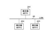
図2は、本発明の第1の実施の形態に係る画像処理装置としてのデジタル複合機をネットワークを介して複数台接続した画像処理システムの構成例を示す概略図である。
[First Embodiment]
FIG. 2 is a schematic diagram showing a configuration example of an image processing system in which a plurality of digital multifunction peripherals as image processing apparatuses according to the first embodiment of the present invention are connected via a network.
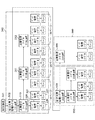
図2において、画像処理システムは、例えば3台のデジタル複合機201(MFP(Multi Function Peripheral)1)、デジタル複合機202(MFP2)、デジタル複合機203(MFP3)から構成されている。デジタル複合機201〜203は、ネットワーク・インタフェースを備えており、ネットワークとしてのLAN(Local Area Network)40を介して接続されると共にLAN40を介してデータの送受信を行う。本実施の形態では、ネットワークを有線LANとした場合を例に挙げているが、無線LANであってもよい。
In FIG. 2, the image processing system includes, for example, three digital multifunction peripherals 201 (MFP (Multi Function Peripheral) 1), a digital multifunction peripheral 202 (MFP 2), and a digital multifunction peripheral 203 (MFP 3). The
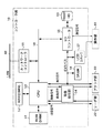
図3は、デジタル複合機201〜203の構成例を示すブロック図である。
FIG. 3 is a block diagram illustrating a configuration example of the
図3において、デジタル複合機201〜203は、それぞれ、デジタル複合機全体の制御を司るコントローラ部10、原稿から画像を読み取る画像入力部であるリーダ部20、用紙に画像を形成する画像出力部であるプリンタ部30の3つのユニットから大略構成されている。更に、コントローラ部10は、ROM(DIMM(Dual Inline Memory Module))51、RAM(DIMM)52、CPU53、画像処理部54、I/Oコントローラ55、SRAM(Static RAM)56、LCD(Liquid Crystal Display)コントローラ57、システムバス58、ネットワークコントローラ59、ハードディスクドライブ(以下HDと略称)60を備えている。
3, each of the
コントローラ部10は、リーダ部20及びプリンタ部30と接続し、一方ではLAN40と接続することで、画像データやデバイス情報の入出力を行う。コントローラ部10において、CPU53は、デジタル複合機全体を制御するものであり、画像処理ブロックを内蔵するコントローラICとして構成されている。また、CPU53は、後述する結合文書管理機能と文書格納管理機能を備えており、制御プログラムに基づいて、図1、図17〜図22のフローチャートに示す処理を実行する。RAM52は、CPU53が動作するためのシステムワークメモリであり、画像データを一時記憶するための画像メモリでもある。ROM51は、ブートROMであり、システムのブートプログラムが格納されている。
The
システムバス58は、PCI(Peripheral Component Interconnect)バス等として構成されており、通信データ、画像データ等の送受信を高速に行うことができる。CPU53は、システムバス58を介してI/Oコントローラ55とネットワークコントローラ59に接続されている。I/Oコントローラ55は、各種のI/Oデバイスを制御する。CPU53は、I/Oコントローラ55を介してHD60にアクセスしたり、画像処理部54にデータを設定したり、LCDコントローラ57により操作部61にデータを表示したりする。ネットワークコントローラ59は、LAN40上の外部装置(他のデジタル複合機やコンピュータ)との間の通信制御を行う。
The
SRAM56は、電池によりバックアップされたメモリであり、デジタル複合機に関する各種の設定が記憶される。LCDコントローラ57は、操作部61に対する表示制御を行う。HD60は、システムソフトウェア、画像データ、システム管理データ、ボックス管理データなどを格納している。操作部61は、ユーザがデジタル複合機の各種設定を行うためのユニットであり、スタートキー等の各種操作キーと、後述の各種画面を表示する表示部とを備えている。CPU53と操作部61との間の通信はI/Oコントローラ55を介して行い、操作部61に表示するデータはCPU53がLCDコントローラ57に対して設定し、LCDコントローラ57が表示データを操作部61に転送する構成となっている。
The SRAM 56 is a memory backed up by a battery, and stores various settings related to the digital multifunction peripheral. The
画像処理部54は、画像データの縮小/拡大/輝度−濃度変換などの各種の画像処理を行うブロックであり、リーダ部20からの入力画像データに対する画像処理部分と、プリンタ部30への出力画像データに対する画像処理部分とから構成されている。リーダ部20により原稿から読み取られた画像データは画像処理部54を介してCPU53に入力され、RAM52に一時的に格納される。CPU53内部には画像データの圧縮処理/伸張処理/回転処理を行うブロックが装備されており、RAM52に格納された画像データにアクセスしてこれら各種の処理を行うことができる。
The image processing unit 54 is a block that performs various types of image processing such as image data reduction / enlargement / brightness-density conversion, and an image processing unit for input image data from the
画像データはCPU53で圧縮処理された後、HD60に転送され、格納される。HD60に格納された画像データはCPU53により読み出すことが可能である。画像データはCPU53で伸張処理された後、プリンタ部30で用紙に画像形成されたり、ネットワークを介してLAN40上の外部装置(他のデジタル複合機やコンピュータ)に送信したりすることができる。
The image data is compressed by the
デジタル複合機は、ネットワークコントローラ59を介してLAN40に接続された他のデジタル複合機やコンピュータと通信することができる。コンピュータからデジタル複合機に送信されたプリントデータは、ネットワークコントローラ59を介してCPU53に入力される。CPU53内のラスタイメージプロセッサ(RIP(Raster Image Processor))が、受信したプリントデータのPDL(Page Description Language)コードをビットマップイメージに展開する。展開された画像データはプリンタ部30に転送されることで、用紙に画像形成が行われる。
The digital multi-function peripheral can communicate with other digital multi-function peripherals and computers connected to the
リーダ部20は、原稿台(不図示)上に載置された原稿または原稿自動給送装置により給送された原稿に光を照射し、原稿からの反射光を光学系(ミラー/レンズ)を介して撮像素子に結像させ、撮像素子により光学像を電気信号に光電変換することで、原稿の画像読み取りを行う画像入力部である。リーダ部20で原稿から読み取った画像データは画像処理部54に送出され、コントローラ部10に送出される。
The
プリンタ部30は、画像データを基に用紙上に画像を形成する画像出力部である。プリンタ部30の画像形成方式としては、感光体ドラムや感光体ベルトを介して用紙上に画像を転写する電子写真方式や、微小ノズルアレイからインクを吐出して用紙上に直接画像を印字するインクジェット方式等などがあるが、本実施の形態では画像形成方式はいずれであっても構わない。プリンタ部30の画像形成動作の起動は、コントローラ部10からの指示によって開始する。プリンタ部30は、異なる用紙サイズまたは用紙向きを選択できるように複数の給紙段を備えると共に、それに対応した用紙カセットを備えており、画像形成された用紙は排紙トレイ上に排出される構成となっている。
The
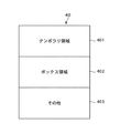
図4は、デジタル複合機201〜203のHD60の記憶領域の構成例を示す図である。
FIG. 4 is a diagram illustrating a configuration example of the storage area of the
図4において、HD60の記憶領域は、使用用途に応じて、テンポラリ領域401と、ボックス領域402と、その他の領域403とに分割されている。テンポラリ領域401は、画像データの出力順序を変えたり、原稿画像を複数部複写する複数部出力においても1回の画像読み取りで行うことができるようにするために、リーダ部20から出力される画像データを一時的に記憶する記憶領域である。
In FIG. 4, the storage area of the
ボックス領域402は、長期的に画像データを格納するための記憶領域である。ボックス領域402を、使用するユーザ毎や部署毎に小さなボックス領域に分割することも可能である。また、ボックス領域402に対し、ボックス名称やパスワードを設定することができる。ユーザはボックスを指定することで画像データをボックス領域402に格納でき、ボックス領域402に格納された画像データを選択して出力したりすることができる。その他の領域403には、デジタル複合機の制御プログラム等が格納されており、電源起動時にRAM52に転送されて制御プログラムが実行される。
The
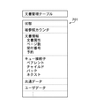
図5は、HD60のボックス領域402内の文書管理構成を示すブロック図である。
FIG. 5 is a block diagram showing a document management configuration in the
図5において、上記図4のボックス領域402に格納された画像データは、ピラミッド上に管理される。画像データ(ページ)530は、1ページの画像データを示し、ページ管理テーブル520により管理される。更に、ページ管理テーブル520は、文書管理テーブル510により管理され、文書管理テーブル510は、結合文書管理テーブル502により管理される構成になっている。
In FIG. 5, the image data stored in the
ボックス領域501は、上記図4のボックス領域402をアクセスした場合のアクセス先を示す。ボックス領域501には、結合文書111.pdf、結合文書222.pdf、結合文書333.pdfの3つの文書が格納されており、結合文書管理テーブル(111.pdf)502、結合文書管理テーブル(222.pdf)503、結合文書管理テーブル(333.pdf)504の3つの文書管理テーブルが格納されていることを示している。図中、540、550、560は、ボックス領域501における格納領域である。
A
結合文書とは、複数の文書が結合したものであり、結合文書111.pdfは、文書111a.pdf、文書111b.pdf、文書111c.pdfの3つの文書から構成され、結合文書テーブル(111.pdf)502は、文書管理テーブル(111a.pdf)510、文書管理テーブル(111b.pdf)511、文書管理テーブル(111c.pdf)512の3つの文書管理テーブルから構成されていることを示している。 A combined document is a combination of a plurality of documents. pdf is the document 111a. pdf, document 111b. pdf, document 111c. The combined document table (111.pdf) 502 includes a document management table (111a.pdf) 510, a document management table (111b.pdf) 511, and a document management table (111c.pdf) 512. It shows that it is composed of three document management tables.
文書111a.pdfは、10ページの画像データ530、531・・・から構成されていることを示している。文書111b.pdfは、20ページの画像データから構成されていることを示している。文書111c.pdfは、30ページの画像データから構成されていることを示している。画像データ530、531は、格納された画像データの1ページを示している。ページ管理テーブル520、521は、画像データ530、531をそれぞれ管理するデータが格納されたテーブルである。
The document 111a.pdf indicates that it is composed of 10 pages of
図6は、結合文書管理テーブルの構成例を示す図である。 FIG. 6 is a diagram illustrating a configuration example of the combined document management table.
図6において、結合文書管理テーブル601は、複数の文書コントロールブロック(「状態」、「被参照カウンタ」・・・)の配列で構成される。文書がコントローラ部10のCPU53の結合文書管理機能で使用されている場合は、対応する文書コントロールブロックの「状態」メンバーが「使用中」になる。
In FIG. 6, the combined document management table 601 is composed of an array of a plurality of document control blocks (“status”, “referenced counter”...). When the document is used in the combined document management function of the
「被参照カウンタ」は、同一文書を複数のジョブで共有するための仕組みを実現するものの1つであり、CPU53の結合文書管理機能により同一文書に対して複数の送信ジョブやプリントジョブが投入された場合の同一文書の参照数を管理するために用いる。文書の消去がCPU53の結合文書管理機能に対して指示された場合、該当文書の「被参照カウンタ」が「−1」された結果「0」になった時点で文書が消去され、「状態」メンバーが「未使用」に変更される。
The “referenced counter” is one that realizes a mechanism for sharing the same document by a plurality of jobs, and a plurality of transmission jobs and print jobs are input to the same document by the combined document management function of the
「文書属性」は、文書に白黒2値画像或いはカラー画像が含まれるか否かを示すものである。「文書数」は、結合された文書の数を示すものである。「受付番号」は、文書が生成されたときの管理通し番号であり、ユーザが自分で生成した文書の識別を行うために用いる。例えば、当該文書に対して送信ジョブやプリントジョブを実行した場合に、ジョブにどの文書が含まれるかをユーザが識別できるようにジョブリストに表示したりする。 “Document attribute” indicates whether the document includes a monochrome binary image or a color image. “Number of documents” indicates the number of combined documents. The “reception number” is a management serial number when a document is generated, and is used for identifying a document generated by the user himself / herself. For example, when a transmission job or print job is executed for the document, the document is displayed in a job list so that the user can identify which document is included in the job.
「キュー接続子」は、関連キューデータの格納先のIDを保持するものである。図5に示した結合文書管理テーブル502を例に挙げると、ペアレントキューはボックス領域501の管理データを示し、チャイルドキューは文書管理テーブル510を示す。また、ネクストキューは結合文書管理テーブル503を示し、バックキューは存在しないことになる。
The “queue connector” holds the ID of the storage destination of the related queue data. Taking the combined document management table 502 shown in FIG. 5 as an example, the parent queue shows the management data of the
図7は、文書管理テーブルの構成例を示す図である。 FIG. 7 is a diagram illustrating a configuration example of the document management table.
図7において、文書管理テーブル701は、結合文書管理テーブル601とほぼ同様の構成を有する。文書管理テーブル701では、結合文書管理テーブル601における文書数の代わりにページ数が設定される。図5に示した504のように、結合文書が存在しない場合には結合文書管理テーブル601に代わって、文書管理テーブル701が参照される。 In FIG. 7, the document management table 701 has almost the same configuration as the combined document management table 601. In the document management table 701, the number of pages is set instead of the number of documents in the combined document management table 601. As shown in 504 in FIG. 5, when there is no combined document, the document management table 701 is referred to instead of the combined document management table 601.
図8は、結合文書管理テーブル用共通データと文書管理テーブル用共通データの構成例を示す図である。 FIG. 8 is a diagram showing a configuration example of the combined document management table common data and the document management table common data.
図8において、結合文書管理テーブル用共通データ・文書管理テーブル用共通データ801における「文書作成者」は、文書が生成された際の情報を管理するためのデータ領域である。「部門コード」は、ユーザがデジタル複合機を操作する場合に入力するユーザが所属する部門コードであり、デジタル複合機の使用状況を部門管理するためのデータ領域である。部門コードは、例えば、部門毎のプリント枚数や通信ジョブを管理するために用いる。また、部門コードは、コントローラ部10のCPU53の文書格納管理機能が管理する文書の文書リスト上にある文書がどの部門で生成されたものであるかを識別するために用いる。
In FIG. 8, “document creator” in the combined document management table common data / document management table
「コンポーネント」は、デジタル複合機内のどの機能部位(コンポーネント)で文書を生成したかを識別するためのデータ領域である。例えば、原稿読み取り文書ならば「SCAN」が「コンポーネント」にセットされ、プリント受信した文書ならば「PRINT」が「コンポーネント」にセットされる。「発信人名称」は、例えば、原稿読み取り時に発信人名称を設定したときにその発信人名称がセットされる。「文書名」は、例えば、ファクシミリによるデータ受信時に遠隔のファクシミリ装置から受信した文書名である。「文書日付」は、文書の生成日付日時秒を示す。 The “component” is a data area for identifying which functional part (component) in the digital multi-function peripheral has generated the document. For example, “SCAN” is set in “component” for a document reading document, and “PRINT” is set in “component” for a document received by printing. The “sender name” is set, for example, when the sender name is set when the document is read. The “document name” is, for example, a document name received from a remote facsimile apparatus when receiving data by facsimile. “Document date” indicates the document generation date and time second.
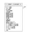
図9は、ページ管理テーブルの構成例を示す図である。 FIG. 9 is a diagram illustrating a configuration example of the page management table.
図9において、ページ管理テーブル901は、文書格納管理手段が管理する画像1枚毎のページ情報を管理するテーブルであり、複数のページコントロールブロックの配列で構成されている。画像データがCPU53の文書格納管理機能によりHD60に格納されている場合は、対応するページコントロールブロックの「状態」メンバーが「使用中」となる。
In FIG. 9, a page management table 901 is a table for managing page information for each image managed by the document storage management means, and is composed of an array of a plurality of page control blocks. When the image data is stored in the
「ページ情報」は、画像(イメージ)属性を管理する管理データ群である。「ファイルID」は、HD60に格納される画像ファイルを特定するためのファイルIDがセットされるものであり、同一原稿に対して管理される画像枚数分の領域が確保されている。「共通データ」は、画像(イメージ)属性を管理するための管理データ領域である。
“Page information” is a management data group for managing image (image) attributes. The “file ID” is set with a file ID for specifying an image file stored in the
図10は、ページ管理テーブル用共通データの構成例を示す図である。 FIG. 10 is a diagram illustrating a configuration example of the common data for the page management table.
図10において、ページ管理テーブル用共通データ1001は、同一原稿に対して管理される画像枚数分の領域が確保されている。「カラー属性」は、画像のカラー情報を示すものであり、画像が白黒であればB/Wが設定され、画像がカラーであればRGB(赤、緑、青)やCMYK(シアン、マゼンタ、イエロー、ブラック)が設定される。「ACS結果」は、オートカラー選択の結果を示すものであり、オートカラー選択の結果に応じてB/W或いはカラーなどが設定される。「Bit/Pixel情報」は、1画素あたりのビット数(階調)を示す。
In FIG. 10, the page management table
「天地情報」は、画像の天地を示す。「解像度」、「画素数」には、それぞれのページの主走査/副走査の解像度、画素数がセットされる。「余白量」は、用紙に対して画像を形成した際の余白量を示す。「圧縮方式」は、RAW/JPEG(Joint Photographic Experts Group)/JBIG(Joint Bi-level Image Experts Group)などの圧縮方式を示す。「画像種別」は、原稿の読み取り時のモードを示し、文字モード、写真モードなどが設定される。その他のデータに関しては、上記と同様に、リーダ部20によって原稿から読み取られた画像データに応じて該当するデータがそれぞれセットされる。
“Top and bottom information” indicates the top and bottom of the image. In “Resolution” and “Number of pixels”, the main scanning / sub-scanning resolution and the number of pixels of each page are set. The “margin amount” indicates the margin amount when an image is formed on a sheet. The “compression method” indicates a compression method such as RAW / JPEG (Joint Photographic Experts Group) / JBIG (Joint Bi-level Image Experts Group). “Image type” indicates a mode at the time of reading a document, and a character mode, a photo mode, and the like are set. As for other data, corresponding data is set in accordance with the image data read from the original by the
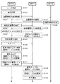
次に、上記構成を有する本実施の形態の画像処理システムのデジタル複合機における画像データ(文書)の結合について、図1及び図11乃至図15を参照しながら詳細に説明する。 Next, the combination of image data (documents) in the digital multi-function peripheral of the image processing system according to the present embodiment having the above-described configuration will be described in detail with reference to FIGS. 1 and 11 to 15.
図11は、画像データ(文書)の結合のイメージを示す図である。 FIG. 11 is a diagram showing an image of combining image data (documents).
図11において、例えば、デジタル複合機(MFP1)のHD60のボックス領域には文書Aが格納されているものとする。デジタル複合機(MFP2)のリーダ部20により文書Bを読み取らせ、文書Bから読み取った画像データをデジタル複合機(MFP1)に送信し、デジタル複合機(MFP1)で文書Aの画像データと文書Bの画像データを結合することで1つの文書として生成するものである。
In FIG. 11, for example, it is assumed that document A is stored in the box area of the
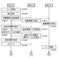
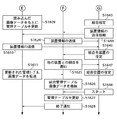
図1は、デジタル複合機の画像データ結合処理を示すフローチャートである。 FIG. 1 is a flowchart showing image data combination processing of the digital multi-function peripheral.
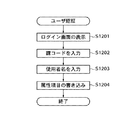
図1において、MFP2はMFP2を使用するユーザの認証を行う(ステップS101)。ユーザ認証については図12のフローチャートに詳細を示す。MFP2はLCDコントローラ57によりログイン初期画面を操作部61に表示する(ステップS1201)。ユーザはログイン初期画面上で所属する課を示す課コードを入力する(ステップS1202)。課コードは必要に応じてMFP使用料金の集計及び課金に使用される。
In FIG. 1, the
続いて、ユーザはログイン初期画面上で使用者名を入力する(ステップS1203)。使用者名が文書情報と共にHD60に格納されるので、格納された文書情報を検索することが容易になる。上記入力によりユーザから得られる内容に応じて確定した属性項目は、HD60の所定領域に書き込まれる(ステップS1204)。
Subsequently, the user inputs the user name on the login initial screen (step S1203). Since the user name is stored in the
図1に戻り、ユーザがMFP2の操作部61により原稿の読取画像データの結合指定を行うと(ステップS102)、MFP2はネットワークコントローラ59によりLAN40上に接続されている他のMFPを検索し、他のMFPに対して装置情報の送信依頼を行う(ステップS103)。他のMFP(本実施の形態では、MFP1、MFP3)は装置情報の送信依頼に応じて、それぞれ装置情報をMFP2に送信する(ステップS121、ステップS141)。
Returning to FIG. 1, when the user designates the combination of the read image data of the original using the operation unit 61 of the MFP 2 (step S <b> 102), the
ユーザはMFP2の操作部61により、他のMFP(MFP1、MFP3)から入手した装置情報を基に、結合先装置(画像データ結合を行う対象の装置)の指定を行う(ステップS105)。本実施の形態では、ユーザが結合先装置としてMFP1を指定するものとする。このとき、MFP2はネットワークコントローラ59によりMFP1に対して結合先装置の指定を行ったことを通知し、MFP1はHD60のボックス領域に格納している画像データの情報として結合文書管理テーブルをMFP2に転送する(ステップS122)。尚、結合文書管理テーブルがない場合には文書管理テーブルを転送する。具体的には、図5の結合管理テーブル502、503、或いは文書管理テーブル504などを転送する。
Based on the device information obtained from the other MFPs (
尚、結合文書管理テーブルの転送に関しては、例えば、ユーザ認証の結果に応じて課コードが一致する場合やユーザが一致する場合などに転送を許可し、それ以外の場合は転送を許可しないといった転送制限を行うようにすれば、セキュリティレベルを向上させることができる。 Regarding transfer of the combined document management table, for example, transfer is permitted when the section code matches or the user matches according to the result of the user authentication, and transfer is not permitted otherwise. If the restriction is made, the security level can be improved.
次に、MFP2はMFP1から入手した結合文書管理テーブルを基に、LCDコントローラ57により文書情報を操作部61に表示し、結合させる文書情報をユーザに選択させる(ステップS106)。MFP2はユーザにより選択された文書情報をMFP1に送付する。
Next, the
MFP1はMFP2で選択された文書情報に応じて、文書データとしてページ管理テーブルをMFP2に転送する(ステップS123)。例えば、図5の結合文書テーブル(111.pdf)502が選択された場合には、文書管理テーブル510、511、512がMFP2に転送される。結合文書でない場合には、文書管理テーブルがMFP2に既に送付されているので、このステップS123は省略される。
The
次に、ユーザはMFP2の操作部61により文書の結合位置を指定し(ステップS107)、原稿をリーダ部20の原稿台にセットし操作部61のスタートキー(不図示)を押下して原稿の読み取りを開始する(ステップS108)。これにより、原稿の読取画像データが順次、MFP2のHD60に格納され、同時に文書データの管理テーブルが作成される(ステップS109)。また、原稿の読み取り開始は、文書の結合先のMFP1にも通知される。ステップS109で作成される管理テーブルは、文書管理テーブルとページ管理テーブルになる。
Next, the user designates a document combining position using the operation unit 61 of the MFP 2 (step S107), sets the document on the document table of the
次に、MFP2はMFP1より入手した文書管理テーブル510〜512と、ステップS109で新たに作成した文書管理テーブルと、指定された結合位置に応じて、結合文書管理テーブル、文書管理テーブルを更新する(ステップS110)。例えば、111c.pdfファイルの後にMFP2で原稿から読み取った画像データが結合される場合には、文書管理テーブル510と511は変更なく、111c.pdfファイル用の文書管理テーブル512のネクストキューに新たな文書管理テーブルの値が設定され、新たな文書管理テーブルのバックキューのアドレスに111c.pdfファイル用の文書管理テーブル512の値が設定される。また、結合文書が増えたため、結合文書管理テーブル502の文書数が書き換えられる。
Next, the
次に、MFP2はMFP1より入手し上記ステップS110で更新された結合文書管理テーブルと文書管理テーブルを、MFP1に転送する。また、MFP2はMFP2で新規に作成された文書管理テーブルとページ管理テーブルとページデータを、MFP1に転送する(ステップS111)。
Next, the
MFP1はMFP2から受信したデータをRAM52に一旦格納し(ステップS124)、結合文書管理テーブル、文書管理テーブルを更新し(ステップS125)、新規結合文書の文書管理テーブル、ページ管理テーブル、ページデータをHD60のボックス領域に格納する。MFP1は格納処理が終了すると、処理の終了をMFP2に通知することにより、一連の処理が終了する(ステップS126)。
The
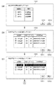
図13(a)は、結合先装置指定画面の表示例、図13(b)と(c)は、結合ファイル指定画面の表示例を示す図である。 FIG. 13A shows a display example of the combined device designation screen, and FIGS. 13B and 13C show display examples of the combined file designation screen.
図13において、(a)は、図1のステップS105の「結合先装置の指定」に対応して操作部61に表示される結合先装置指定画面1301を示すものであり、本画像処理システムのデジタル複合機(MFP1、MFP2、MFP3)が表示されている。結合先装置指定画面1301上で、結合先装置の指定を行うことができる。ユーザは表示されたメッセージに従い、例えばMFP1を選択してOKキー1311を押下する。尚、1312は戻るキーである。
13A shows a join destination
(b)、(c)は、それぞれ図1のステップS106の「結合先ファイルの選択」に対応して操作部61に表示される結合先ファイル指定画面1302、1303を示すものであり、MFP1のボックス領域に格納されたファイルが表示されている。結合先ファイル指定画面1302、1303上で、結合先ファイルの指定を行うことができる。ユーザは表示されたメッセージに従い、例えばファイル111.pdfを選択してOKキー1311を押下する。
(B) and (c) respectively show the combination destination
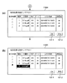
図14(a)と(b)は、結合位置指定画面の表示例を示す図である。 FIGS. 14A and 14B are diagrams showing display examples of the coupling position designation screen.
図14において、(a)、(b)は、それぞれ図1のステップS107の「結合位置の指定」に対応して操作部61に表示される結合位置指定画面1304、1305を示すものであり、結合された文書を構成する各文書が表示されている。結合位置指定画面1304、1305上で、各文書のどの部分に原稿から新たに読み取る画像データを結合させるかを指示することができる。ユーザは表示されたメッセージに従い、結合位置を指定した後、OKキー1311を押下し、操作部61のスタートキー(不図示)を押下して処理を開始させる。
14, (a) and (b) respectively show coupling position designation screens 1304 and 1305 displayed on the operation unit 61 in correspondence with “designation of coupling position” in step S107 of FIG. Each document constituting the merged document is displayed. On the combination position designation screens 1304 and 1305, it can be instructed to which part of each document the image data to be newly read from the original is combined. In accordance with the displayed message, the user designates the coupling position, and then presses the
即ち、本実施の形態では、操作部61の結合位置指定画面1304、1305上で、画像データ送信元のデジタル複合機で文書から読み取った画像データを、画像データ結合先のデジタル複合機の文書の画像データの任意ページに付加する指定を行うことが可能である。 That is, in the present embodiment, the image data read from the document by the digital multifunction peripheral of the image data transmission source on the combination position designation screens 1304 and 1305 of the operation unit 61 is changed to the document of the digital multifunction peripheral of the image data combination destination. It is possible to specify to add to an arbitrary page of image data.
図15は、画像データ(文書)結合処理後のHD60のボックス領域内の文書管理構成を示すブロック図である。
FIG. 15 is a block diagram showing a document management configuration in the box area of the
図15において、上記図1で説明した画像データ結合処理の結果、540'に示すように、図5のボックス領域内の文書管理構成に対して、540'内の2点鎖線で囲んだ570内の文書管理テーブル、各ページ管理テーブル、各ページが追加され、文書管理テーブル512に対してのリンクが形成されている。 In FIG. 15, as a result of the image data combining process described with reference to FIG. 1, as shown by 540 ′, the document management configuration in the box area of FIG. Document management table, each page management table, and each page are added, and a link to the document management table 512 is formed.
以上説明したように、本実施の形態によれば、結合先のMFPは、結合先のMFPの画像データを管理する管理テーブルを送信元のMFPに送付する。送信元のMFPでは、画像データ結合位置を指定し、送信元のMFPの画像データを管理する管理テーブルを作成し、結合先の管理テーブルに送信元の管理テーブルを付加した管理テーブルを作成し、送信元のMFPの画像データと管理テーブルを結合先のMFPに転送する。結合先のMFPは、管理テーブルと結合位置を基に、送信元のMFPの画像データと結合先のMFPの画像データを結合する。 As described above, according to the present embodiment, the combination destination MFP sends the management table for managing the image data of the combination destination MFP to the transmission source MFP. In the transmission source MFP, an image data combination position is designated, a management table for managing the image data of the transmission source MFP is created, a management table in which the transmission source management table is added to the combination destination management table is created, The image data of the transmission source MFP and the management table are transferred to the combination destination MFP. The combination destination MFP combines the image data of the transmission source MFP and the image data of the combination destination MFP based on the management table and the combination position.
これにより、大量の原稿を複数のMFPを使用して読み取り、大量の原稿から読み取った画像を1つの電子データとして生成する画像データ結合処理(電子化処理)を容易に且つ高速に行うことができる。 Accordingly, it is possible to easily and quickly perform image data combining processing (digitization processing) for reading a large amount of originals using a plurality of MFPs and generating an image read from the large amount of originals as one electronic data. .
[第2の実施の形態]
本発明の第2の実施の形態は、上述した第1の実施の形態に対して、下記の点において相違する。本実施の形態のその他の要素は、上述した第1の実施の形態(図2、図3)の対応するものと同一なので、説明を省略する。
[Second Embodiment]
The second embodiment of the present invention is different from the first embodiment described above in the following points. The other elements of the present embodiment are the same as the corresponding ones of the first embodiment (FIGS. 2 and 3) described above, and a description thereof will be omitted.
上述した第1の実施の形態では、2台のデジタル複合機(MFP)を使用した場合の画像データ結合について説明した。これに対し、本実施の形態では、3台のデジタル複合機(MFP)を使用した場合の画像データ結合について説明する。 In the above-described first embodiment, image data combination when two digital multifunction peripherals (MFPs) are used has been described. In contrast, in the present embodiment, image data combination when three digital multifunction peripherals (MFPs) are used will be described.
図16は、本実施の形態に係る3台のデジタル複合機(MFP1、MFP2、MFP3)を使用した場合の画像データ結合のイメージを示す図である。 FIG. 16 is a diagram showing an image data combination image when three digital multifunction peripherals (MFP1, MFP2, MFP3) according to the present embodiment are used.
図16において、MFP1のボックス領域に格納された文書Aの画像データに対して、MFP2を使用して文書Bから画像データを読み取り、文書Bの画像データを結合させる。更に、MFP1のボックス領域に格納された文書Aの画像データに対して、MFP3を使用して文書Cから画像データを読み取り、文書Cの画像データを結合させる。これにより、MFP1のボックス領域に文書A、文書B、文書Cの各画像データが結合され、1つの文書として生成される。
In FIG. 16, the image data of document A stored in the box area of
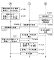
具体的に、図17、図18、図19のフローチャートを用いて画像データ結合の詳細を説明する。 Specifically, details of image data combination will be described with reference to the flowcharts of FIGS. 17, 18, and 19.
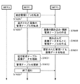
図17、図18は、画像データ結合処理を示すフローチャートである。 17 and 18 are flowcharts showing the image data combining process.
図17、図18において、MFP2のステップS1601〜ステップS1609に示す処理は、図1のMFP2のステップS101〜ステップS110に示す処理と同様である。また、MFP1のステップS1621〜ステップS1623、MFP3のステップS1641に示す処理も、図1のMFP1のステップS121〜ステップS123、MFP3のステップS141に示す処理と同様である。上記ステップの処理によりMFP1のボックス領域に格納された画像データに対して画像データ結合を行うため、MFP2を使用して原稿の読み取りを開始し、画像データの格納を開始する。
17 and 18, the processing shown in steps S1601 to S1609 of the
また、MFP3を使用して原稿の読み取りを開始し、MFP1のボックス領域に格納された画像データに対して更に画像データ結合を行う。これに先立ち、MFP3はMFP3を使用するユーザの認証をステップS1601と同様に行う(ステップS1642)。ユーザがMFP3の操作部61により原稿の読取画像データの結合指定を行うと(ステップS1643)、MFP3はネットワークコントローラ59によりLAN40上に接続されている他のMFPを検索し、他のMFPに対して装置情報の送信依頼を行う(ステップS1644)。他のMFP(MFP2、MFP1)は装置情報の送信依頼に応じて、それぞれ装置情報をMFP3に送信する(ステップS1610、ステップS1624)。
Also, reading of a document is started using the
ユーザはMFP3の操作部61により、他のMFP(MFP2、MFP1)から入手した装置情報に基づき結合先装置(画像データ結合を行う対象の装置)の指定を行う(ステップS1645)。本実施の形態では、ユーザが結合先装置としてMFP1を指定するものとする。このとき、MFP1はMFP2との画像データ結合処理中であるため、MFP3からの画像データ結合先として指定されたMFP1は、他の装置との競合が発生していることをMFP3に通知する(ステップS1625)。
The user uses the operation unit 61 of the
他方、MFP2は原稿からの画像の読み取り及び画像データの格納が終了した後、管理テーブルを更新し、管理テーブルを画像データと共にMFP1に転送する(ステップS1611)。MFP1は上記図1で説明した手順と同様に、結合管理管理テーブル、管理テーブル、画像データをHD60のボックス領域に格納し(ステップS1626)、管理テーブルを更新する(ステップS1627)。MFP1は格納処理が終了すると、処理の終了をMFP2に通知する(ステップS1628)。
On the other hand, after reading the image from the document and storing the image data, the
図19は、画像データ結合処理を示すフローチャートである。 FIG. 19 is a flowchart showing the image data combining process.
図19において、MFP3のステップS1646〜ステップS1651に示す処理は、図1のMFP2のステップS106〜ステップS111に示す処理と同様であり、MFP1のステップS1629〜ステップS1633に示す処理は、図1のMFP1のステップS122〜ステップS126に示す処理と同様である。
19, the processes shown in steps S1646 to S1651 of the
MFP1とMFP2による画像データ結合が完了すると、MFP1は画像データ結合要求のあったMFP3に対して、MFP1の結合管理テーブルを転送する(ステップS1629)。結合管理テーブルを入手したMFP3のユーザは操作部61により結合先ファイルの選択を行い(ステップS1646)、MFP1は選択された画像データの管理テーブルをMFP3に転送する(ステップS1630)。MFP1から選択された画像データの管理テーブルを入手すると、ユーザはMFP3の操作部61により管理テーブルから画像データの結合位置を指定し(ステップS1647)、操作部61のスタートキーを押下し(ステップS1648)、原稿画像の読み取りを開始する(ステップS1649)。
When the image data combination by the
MFP3は原稿から読み取った画像データ、MFP1から入手した結合管理テーブル、管理テーブルを更新し(ステップS1650)、更新された管理テーブル、画像データをMFP1に転送する(ステップS1651)。MFP1は結合管理テーブル、画像データをHD60のボックス領域に格納し(ステップS1631)、管理テーブルを更新する(ステップS1632)。MFP1は格納処理が終了すると、処理の終了をMFP3に通知する(ステップS1633)。
The
尚、本実施の形態では、3台のデジタル複合機を使用して画像データ結合を行った場合を例に挙げたが、より多数台のデジタル複合機を使用して画像データ結合を行う場合にも適用することができる。 In this embodiment, the case where image data combination is performed using three digital multifunction peripherals has been described as an example. However, when image data combination is performed using a larger number of digital multifunction peripherals. Can also be applied.
以上説明したように、本実施の形態によれば、上述した第1の実施の形態と同様に、大量の原稿を複数のMFPを使用して読み取り、大量の原稿から読み取った画像を1つの電子データとして生成する画像データ結合処理(電子化処理)を容易に且つ高速に行うことができる。 As described above, according to the present embodiment, as in the first embodiment described above, a large number of originals are read using a plurality of MFPs, and an image read from a large number of originals is converted into one electronic document. Image data combining processing (digitization processing) generated as data can be performed easily and at high speed.
特に、本実施の形態では、大量の原稿を3台のMFPを使用して読み取り、大量の原稿から読み取った画像を1つの電子データとして生成する電子化処理を行う際に、3つの画像ファイルをそれぞれ生成するのではなく、1つの画像ファイルとして生成することが可能となる。 In particular, in the present embodiment, when performing a digitization process for reading a large amount of originals using three MFPs and generating an image read from the large amount of originals as one electronic data, Instead of generating each, it is possible to generate as one image file.
[第3の実施の形態]
本発明の第3の実施の形態は、上述した第2の実施の形態に対して、下記の点において相違する。本実施の形態のその他の要素は、上述した第1の実施の形態(図2、図3)の対応するものと同一なので、説明を省略する。
[Third Embodiment]
The third embodiment of the present invention is different from the above-described second embodiment in the following points. The other elements of the present embodiment are the same as the corresponding ones of the first embodiment (FIGS. 2 and 3) described above, and a description thereof will be omitted.
上述した第2の実施の形態では、3台のデジタル複合機を使用して画像データ結合を行った場合について説明したが、MFP1とMFP2による画像データ結合が終了するまで、MFP3による原稿画像の読み取りが開始されなかった。これに対し、本実施の形態では、原稿画像の読み取り処理までの開始時間の削減を図るようにする例について説明する。
In the above-described second embodiment, the case where image data combination is performed using three digital multifunction peripherals has been described. However, reading of an original image by
具体的に、図20、図21、図22のフローチャートを用いて画像データ結合の詳細を説明する。 Specifically, the details of the image data combination will be described with reference to the flowcharts of FIGS. 20, 21, and 22.
図20、図21は、本実施の形態に係る画像データ結合処理を示すフローチャートである。 20 and 21 are flowcharts showing the image data combining process according to the present embodiment.
図20、図21において、図17、図18と相違する点は、MFP3でステップS1647、ステップS1648に示す処理のタイミングを変更した点である。MFP1はMFP2との画像データ結合処理中であるため、MFP3からの画像データ結合先として指定されたMFP1は、他の装置との競合が発生していることをMFP3に通知する(ステップS1625)。
20 and 21 are different from FIGS. 17 and 18 in that the processing timings shown in steps S1647 and S1648 in the
このとき、MFP3からの画像データ結合を行うにあたり、文書と文書との間に新規画像データを結合するケースはあまりなく、新規画像データを文書の先頭に挿入する或いは文書の末尾に付け加えるというケースがほとんどである。また、MFP1において、MFP2からの画像データを結合中であるので、該画像データ結合の終了後にMFP3からの所望の結合先ファイルが変更されている可能性がある。もし文書の順番を間違って格納したとしても、結合管理テーブルにより各文書が管理されているため、後から文書の入れ替えが可能である。
At this time, when combining image data from the
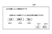
ユーザはMFP3の操作部61の図23に示す結合位置指定画面2301上で、表示されたメッセージに従い画像データ結合位置について文書の先頭或いは文書の末尾(最後)という指定を行う(ステップS1647)。結合位置指定画面2301の先頭キー2321或いは最後キー2323を押下してOKキー2311を押下することにより、画像データ結合位置を指定することができる。これにより、MFP1がMFP2との間で画像データ結合処理中でも、MFP3を使用しての画像データ結合処理を開始することが可能となる。
The user designates the start position of the document or the end (end) of the document for the image data combination position on the combination
他方、結合位置指定画面2301の画像中キー2322を押下した場合には、MFP3はMFP1とMFP2の画像データ結合処理が終了するまで待つことになる。この場合、以降の処理は、上述した第2の実施の形態と同様になる。
On the other hand, when the middle image key 2322 on the combination
ユーザは上記ステップS1647で画像データ結合位置を例えば文書の末尾(最後)に指定し、原稿をMFP3の原稿台にセットして操作部61のスタートキー(不図示)を押下することにより、原稿画像の読み取りを開始させる(ステップS1648)。
In step S1647, the user designates the image data combination position, for example, at the end (last) of the document, sets the document on the document table of the
図22は、画像データ結合処理を示すフローチャートである。 FIG. 22 is a flowchart showing the image data combining process.
図22において、MFP3は原稿から画像の読み取り、読み取った画像データの格納、結合文書管理テーブル、文書管理テーブルの作成を行う(ステップS1649)。他方、MFP1とMFP2による画像データ結合が完了すると、MFP1は結合管理テーブルと管理テーブルをMFP3に転送する(ステップS1629、ステップS1630)。この後の処理は、第2の実施の形態と同様であり、説明を省略する。
In FIG. 22, the
以上説明したように、本実施の形態によれば、大量の原稿を3台のMFPを使用して読み取り、大量の原稿から読み取った画像を1つの電子データとして生成する電子化処理を行う際に、2台のMFPが画像データ結合処理中の場合、他のMFPの画像データを結合先のMFPの画像データの先頭或いは末尾に付加する指定を行う。 As described above, according to the present embodiment, a large number of originals are read using three MFPs, and an electronic process for generating an image read from a large number of originals as one electronic data is performed. When two MFPs are in the process of combining image data, designation is made to add the image data of another MFP to the head or the end of the image data of the MFP as the combining destination.
これにより、2台のMFPが画像データ結合処理中でも、他のMFPを使用した画像データ結合処理を開始することができるので、より高速に電子化処理を進めることができる。 As a result, even when two MFPs are in the image data combination process, the image data combination process using another MFP can be started, so that the digitization process can proceed at a higher speed.
[他の実施の形態]
上記第1乃至第3の実施の形態では、図2に示す画像処理システムにおいて図1等のフローチャートに示す処理を例に挙げたが、本発明は上記のものに限定されるものではなく、本発明の要旨を逸脱しない範囲で種々変更可能であることは言うまでもない。例えば、画像処理システムの構成としては、図2の構成以外に、任意台数のデジタル複合機とスキャナをネットワーク接続する構成や、任意台数のデジタル複合機とスキャナとプリンタをネットワーク接続する構成や、任意台数のデジタル複合機/スキャナとコンピュータをネットワーク接続する構成などが考えられる。また、文書結合管理テーブル、文書管理テーブル、ページ管理テーブルの構成も、画像処理システムの利用形態に応じて各管理テーブル内の項目を適宜、追加/削除/変更することが可能である。
[Other embodiments]
In the first to third embodiments, the processing shown in the flowchart of FIG. 1 and the like is given as an example in the image processing system shown in FIG. 2, but the present invention is not limited to the above, It goes without saying that various changes can be made without departing from the scope of the invention. For example, as the configuration of the image processing system, in addition to the configuration of FIG. 2, a configuration in which an arbitrary number of digital multi-function peripherals and scanners are connected to a network, a configuration in which an arbitrary number of digital multi-function peripherals, scanners, and printers are connected to a network, A configuration in which a number of digital multifunction peripherals / scanners and computers are connected via a network is conceivable. The configuration of the document combination management table, the document management table, and the page management table can also be added / deleted / changed as appropriate in the items in each management table according to the usage form of the image processing system.
上記第1乃至第3の実施の形態では、複数のデジタル複合機を使用した際の画像データ結合を例に挙げたが、本発明はこれに限定されるものではなく、単一のデジタル複合機を複数回使用した際の画像データ結合にも適用することができる。複数のデジタル複合機を使用するか単一のデジタル複合機を複数回使用するかの選択は、操作部61から選択するようにすればよい。 In the first to third embodiments, image data combination when a plurality of digital multifunction peripherals are used has been described as an example. However, the present invention is not limited to this, and a single digital multifunction peripheral is used. Can also be applied to image data combination when used in multiple times. The selection of whether to use a plurality of digital multifunction peripherals or a single digital multifunction peripheral multiple times may be selected from the operation unit 61.
本発明は、上述した実施の形態の機能を実現するソフトウェアのプログラム(図1、図17〜図22のフローチャート)をコンピュータ又はCPUに供給し、そのコンピュータ又はCPUが該供給されたプログラムを読出して実行することによって、達成することができる。 The present invention supplies a software program (flowcharts in FIGS. 1 and 17 to 22) for realizing the functions of the above-described embodiments to a computer or CPU, and the computer or CPU reads the supplied program. This can be accomplished by doing.
この場合、上記プログラムは、該プログラムを記録した記憶媒体から直接供給されるか、又はインターネット、商用ネットワーク、若しくはローカルエリアネットワーク等に接続される不図示の他のコンピュータやデータベース等からダウンロードすることにより供給される。 In this case, the program is directly supplied from a storage medium storing the program, or downloaded from another computer or database (not shown) connected to the Internet, a commercial network, a local area network, or the like. Supplied.
上記プログラムの形態は、オブジェクトコード、インタプリタにより実行されるプログラムコード、OS(オペレーティングシステム)に供給されるスクリプトデータ等の形態から成ってもよい。 The form of the program may be in the form of object code, program code executed by an interpreter, script data supplied to an OS (operating system), and the like.
また、本発明は、上述した実施の形態の機能を実現するソフトウェアのプログラムを記憶した記憶媒体をコンピュータ又はCPUに供給し、そのコンピュータ又はCPUが記憶媒体に記憶されたプログラムを読出して実行することによっても、達成することができる。 The present invention also supplies a computer or CPU with a storage medium storing a software program that implements the functions of the above-described embodiments, and the computer or CPU reads and executes the program stored in the storage medium. Can also be achieved.
この場合、記憶媒体から読出されたプログラムコード自体が上述した各実施の形態の機能を実現すると共に、そのプログラムコードを記憶した記憶媒体は本発明を構成する。 In this case, the program code itself read from the storage medium realizes the functions of the above-described embodiments, and the storage medium storing the program code constitutes the present invention.
プログラムコードを記憶する記憶媒体としては、例えば、ROM、RAM、NV−RAM、フロッピー(登録商標)ディスク、ハードディスク、光ディスク(登録商標)、光磁気ディスク、CD−ROM、MO、CD−R、CD−RW、DVD−ROM、DVD−RAM、DVD−RW、DVD+RW、磁気テープ、不揮発性のメモリカード等がある。 As a storage medium for storing the program code, for example, ROM, RAM, NV-RAM, floppy (registered trademark) disk, hard disk, optical disk (registered trademark), magneto-optical disk, CD-ROM, MO, CD-R, CD -RW, DVD-ROM, DVD-RAM, DVD-RW, DVD + RW, magnetic tape, nonvolatile memory card, etc.
上述した実施の形態の機能は、コンピュータから読出されたプログラムコードを実行することによるばかりでなく、コンピュータ上で稼動するOS等がプログラムコードの指示に基づいて実際の処理の一部又は全部を行うことによっても実現することができる。 The function of the above-described embodiment is not only by executing the program code read from the computer, but the OS or the like running on the computer performs part or all of the actual processing based on the instruction of the program code. Can also be realized.
更に、本発明は、前述した実施の形態を実現するソフトウェアのプログラムがネットワーク上のデータベース又はホームページから通信プログラムによリーダウンロードされ、このプログラムを読出して実行することによって達成することができる。 Furthermore, the present invention can be achieved by downloading a software program for realizing the above-described embodiment from a database on a network or a homepage by a communication program, and reading and executing this program.
上記プログラムは、クライアントコンピュータのブラウザを用いてインターネットのホームページに接続し、該ホームページからコンピュータプログラム自体、又は自動インストール機能を含む圧縮ファイルをハードディスク等の記憶媒体にダウンロードすることによっても供給することができる。 The above program can also be supplied by connecting to a homepage on the Internet using a browser of a client computer and downloading the computer program itself or a compressed file including an automatic installation function from the homepage to a storage medium such as a hard disk. .
また、上記プログラムは、プログラムコードを暗号化した上で格納したCD−ROM等の記憶媒体をユーザに配布し、所定の条件をクリアしたユーザに対し、インターネットを介してホームページから暗号化を解く鍵情報をダウンロードさせ、その鍵情報を使用することにより暗号化されたプログラムコードを実行してコンピュータにインストールさせることによっても供給することができる。 The above program distributes a storage medium such as a CD-ROM stored after encrypting the program code to the user, and provides a key for decrypting the encryption from the homepage via the Internet to the user who has cleared a predetermined condition. It can also be provided by downloading the information and using the key information to execute the encrypted program code and install it on the computer.
上述した実施の形態の機能は、プログラムコードを複数のファイルに分割し、夫々のファイルを異なるホームページからダウンロードすることによっても実現することができる。即ち、本発明の機能処理をコンピュータで実現させるためのプログラムファイルを複数のユーザに対してダウンロードさせるWWWサーバも、本発明を構成する。 The functions of the embodiments described above can also be realized by dividing the program code into a plurality of files and downloading each file from a different home page. That is, a WWW server that allows a plurality of users to download a program file for realizing the functional processing of the present invention on a computer also constitutes the present invention.
また、上述した実施の形態の機能は、記憶媒体から読出されたプログラムが、コンピュータに挿入された機能拡張ボード又はコンピュータに接続された機能拡張ユニットに備えられたメモリに書込まれた後、そのプログラムの指示に基づき、その機能拡張ボード又は機能拡張ユニットに備えられたCPU又はMPU等が実際の処理の一部又は全部を実行することによっても実現することができる。 Further, the functions of the above-described embodiment are obtained by writing a program read from a storage medium into a function expansion board inserted in a computer or a memory provided in a function expansion unit connected to the computer, and It can also be realized by the CPU or MPU provided in the function expansion board or function expansion unit executing part or all of the actual processing based on the instructions of the program.
10 コントローラ部
20 リーダ部
30 プリンタ部
40 LAN
53 CPU(第1の取得手段、第2の取得手段、指定手段、第1の作成手段、第2の作成手段、転送手段、送付手段、結合手段)
59 ネットワークコントローラ(送付手段、転送手段)
60 HD
61 操作部(指定手段、選択手段)
201〜203 デジタル複合機(画像処理装置、複合装置)
10
53 CPU (first acquisition means, second acquisition means, designation means, first creation means, second creation means, transfer means, sending means, combining means)
59 Network controller (sending means, transferring means)
60 HD
61 Operation part (designation means, selection means)
201-203 Digital MFP (image processing device, MFP)
Claims (16)
送信元の画像処理装置は、
前記結合先の画像処理装置の画像データを管理する結合先管理テーブルを取得する第1の取得手段と、
前記送信元の画像処理装置の画像データと前記結合先の画像処理装置の画像データとの結合を指定する指定手段と、
前記送信元の画像データを管理する送信元管理テーブルを作成する第1の作成手段と、
前記結合先管理テーブルに前記送信元管理テーブルを付加した更新管理テーブルを作成する第2の作成手段と、
前記送信元の画像データと前記更新管理テーブルを前記結合先の画像処理装置に転送する転送手段と、
を備え、
結合先の画像処理装置は、
前記結合先管理テーブルを前記送信元の画像処理装置に送付する送付手段と、
前記送信元の画像データと、前記更新管理テーブルを取得する第2の取得手段と、
前記更新管理テーブルに基づいて、前記結合先の画像データと前記送信元の画像データとを結合する結合手段と、
を備えることを特徴とする画像処理システム。 An image processing system in which a transmission source image processing apparatus that transmits image data and a combination destination image processing apparatus that acquires image data from the transmission source image processing apparatus and combines the image data are communicably connected. And
The source image processing device is
First acquisition means for acquiring a combining destination management table for managing image data of the combining destination image processing apparatus;
Designating means for designating the combination of the image data of the transmission source image processing apparatus and the image data of the combination destination image processing apparatus;
First creation means for creating a transmission source management table for managing the transmission source image data;
Second creation means for creating an update management table in which the transmission source management table is added to the combination destination management table;
Transfer means for transferring the image data of the transmission source and the update management table to the image processing apparatus of the combination destination;
With
The image processing apparatus of the combination destination
Sending means for sending the combination destination management table to the image processing apparatus of the transmission source;
Second acquisition means for acquiring the image data of the transmission source and the update management table;
Based on the update management table, combining means for combining the image data of the combining destination and the image data of the transmission source;
An image processing system comprising:
送信元の画像データの入力をする画像データ入力手段と、
結合先の画像データと送信元の画像データとを結合する際に、前記結合先の画像データを管理する結合先管理テーブルを送信元の画像処理装置に送付する送付手段と、
前記結合先管理テーブルを取得する第1の取得手段と、
前記送信元の画像データと前記結合先の画像データとの結合を指定する指定手段と、
前記送信元の画像データを管理する送信元管理テーブルを作成する第1の作成手段と、
前記結合先管理テーブルに前記送信元管理テーブルを付加した更新管理テーブルを作成する第2の作成手段と、
前記送信元の画像データと前記更新管理テーブルを結合先の画像処理装置に転送する転送手段と、
前記送信元の画像データと前記更新管理テーブルを取得する第2の取得手段と、
前記更新管理テーブルに基づいて、前記結合先の画像データと前記送信元の画像データとを結合する結合手段と、
を備えることを特徴とする画像処理装置。 An image processing apparatus capable of transmitting, acquiring and combining image data,
Image data input means for inputting the source image data;
A sending means for sending a joining destination management table for managing the joining destination image data to the sending image processing apparatus when joining the joining destination image data and the sending source image data;
First acquisition means for acquiring the combination destination management table;
Designating means for designating the combination of the image data of the transmission source and the image data of the combination destination;
First creation means for creating a transmission source management table for managing the transmission source image data;
Second creation means for creating an update management table in which the transmission source management table is added to the combination destination management table;
Transfer means for transferring the image data of the transmission source and the update management table to an image processing apparatus of a combination destination;
Second acquisition means for acquiring the transmission source image data and the update management table;
Based on the update management table, combining means for combining the image data of the combining destination and the image data of the transmission source;
An image processing apparatus comprising:
画像データの入力をする画像データ入力手段と、
前記結合先の画像処理装置の画像データを管理する結合先管理テーブルを取得する取得手段と、
前記画像データ入力手段により入力された画像データと前記結合先の画像データとの結合を指定する指定手段と、
前記画像データ入力手段により入力された画像データを管理する送信元管理テーブルを作成する第1の作成手段と、
前記結合先管理テーブルに前記送信元管理テーブルを付加した更新管理テーブルを作成する第2の作成手段と、
前記画像データ入力手段により入力された画像データと前記更新管理テーブルを前記結合先の画像処理装置に転送する転送手段と、
を備えることを特徴とする画像処理装置。 An image processing apparatus as a transmission source that transmits image data to an image processing apparatus as a combining destination that combines image data,
Image data input means for inputting image data;
An acquisition unit for acquiring a combination management table for managing image data of the image processing apparatus of the combination destination;
Designating means for designating the combination of the image data input by the image data input means and the image data to be combined;
First creation means for creating a transmission source management table for managing image data input by the image data input means;
Second creation means for creating an update management table in which the transmission source management table is added to the combination destination management table;
Transfer means for transferring the image data input by the image data input means and the update management table to the image processing apparatus to be combined;
An image processing apparatus comprising:
前記結合先の画像処理装置の画像データと前記送信元の画像処理装置の画像データとを結合する際に、前記結合先の画像処理装置の画像データを管理する結合先管理テーブルを前記送信元の画像処理装置に送付する送付手段と、
前記送信元の画像処理装置の画像データを管理する送信元管理テーブルに前記結合先管理テーブルが付加された更新管理テーブルと、前記送信元の画像処理装置の画像データとを取得する取得手段と、
前記更新管理テーブルに基づいて、前記結合先の画像処理装置の画像データと前記送信元の画像処理装置の画像データとを結合する結合手段と、
を備えることを特徴とする画像処理装置。 A combined image processing apparatus that acquires image data from a transmission source image processing apparatus and combines image data,
When combining the image data of the destination image processing apparatus and the image data of the source image processing apparatus, a destination management table for managing the image data of the destination image processing apparatus is stored in the source Sending means for sending to the image processing apparatus;
An update management table in which the combination destination management table is added to a transmission source management table that manages image data of the transmission source image processing apparatus; and an acquisition unit that acquires image data of the transmission source image processing apparatus;
Based on the update management table, combining means for combining the image data of the image processing apparatus of the combination destination and the image data of the image processing apparatus of the transmission source;
An image processing apparatus comprising:
送信元の画像データの入力をする画像データ入力工程と、
結合先の画像データと送信元の画像データとを結合する際に、前記結合先の画像データを管理する結合先管理テーブルを送信元の画像処理装置に送付する送付工程と、
前記結合先管理テーブルを取得する第1の取得工程と、
前記送信元の画像データと前記結合先の画像データとの結合を指定する指定工程と、
前記送信元の画像データを管理する送信元管理テーブルを作成する第1の作成工程と、
前記結合先管理テーブルに前記送信元管理テーブルを付加した更新管理テーブルを作成する第2の作成工程と、
前記送信元の画像データと前記更新管理テーブルを結合先の画像処理装置に転送する転送工程と、
前記送信元の画像データと前記更新管理テーブルを取得する第2の取得工程と、
前記更新管理テーブルに基づいて、前記結合先の画像データと前記送信元の画像データとを結合する結合工程と、
を有することを特徴とする画像処理装置の制御方法。 A method for controlling an image processing apparatus capable of transmitting, acquiring and combining image data,
An image data input process for inputting image data of a transmission source;
A sending step of sending a joining destination management table for managing the joining destination image data to the sending image processing apparatus when joining the joining destination image data and the sending source image data;
A first acquisition step of acquiring the combination destination management table;
A designation step for designating the combination of the image data of the transmission source and the image data of the combination destination;
A first creation step of creating a transmission source management table for managing the transmission source image data;
A second creation step of creating an update management table in which the transmission source management table is added to the combination destination management table;
A transfer step of transferring the image data of the transmission source and the update management table to an image processing apparatus of a combination destination;
A second acquisition step of acquiring the image data of the transmission source and the update management table;
Based on the update management table, a combining step of combining the image data of the combining destination and the image data of the transmission source;
A control method for an image processing apparatus, comprising:
画像データの入力をする画像データ入力工程と、
前記結合先の画像処理装置の画像データを管理する結合先管理テーブルを取得する取得工程と、
前記画像データ入力工程により入力された画像データと前記結合先の画像データとの結合を指定する指定工程と、
前記画像データ入力工程により入力された画像データを管理する送信元管理テーブルを作成する第1の作成工程と、
前記結合先管理テーブルに前記送信元管理テーブルを付加した更新管理テーブルを作成する第2の作成工程と、
前記画像データ入力工程により入力された画像データと前記更新管理テーブルを前記結合先の画像処理装置に転送する転送工程と、
を有することを特徴とする画像処理装置の制御方法。 A control method of a transmission source image processing apparatus that transmits image data to a combination destination image processing apparatus that combines image data,
An image data input process for inputting image data;
An acquisition step of acquiring a combination destination management table for managing image data of the image processing apparatus of the combination destination;
A designation step for designating the combination of the image data input by the image data input step and the image data of the combination destination;
A first creation step of creating a transmission source management table for managing the image data input by the image data input step;
A second creation step of creating an update management table in which the transmission source management table is added to the combination destination management table;
A transfer step of transferring the image data input in the image data input step and the update management table to the image processing apparatus of the combination destination;
A control method for an image processing apparatus, comprising:
前記結合先の画像処理装置の画像データと前記送信元の画像処理装置の画像データとを結合する際に、前記結合先の画像処理装置の画像データを管理する結合先管理テーブルを前記送信元の画像処理装置に送付する送付工程と、
前記送信元の画像処理装置の画像データを管理する送信元管理テーブルに前記結合先管理テーブルが付加された更新管理テーブルと、前記送信元の画像処理装置の画像データとを取得する取得工程と、
前記更新管理テーブルに基づいて、前記結合先の画像処理装置の画像データと前記送信元の画像処理装置の画像データとを結合する結合工程と、
を有することを特徴とする画像処理装置の制御方法。 A method of controlling a destination image processing apparatus that acquires image data from a source image processing apparatus and combines the image data,
When combining the image data of the destination image processing apparatus and the image data of the source image processing apparatus, a destination management table for managing the image data of the destination image processing apparatus is stored in the source A sending process for sending to the image processing apparatus;
An update management table in which the combination destination management table is added to a transmission source management table for managing image data of the transmission source image processing apparatus; and an acquisition step of acquiring image data of the transmission source image processing apparatus;
Based on the update management table, a combining step of combining the image data of the image processing apparatus of the combining destination and the image data of the image processing apparatus of the transmission source;
A control method for an image processing apparatus, comprising:
Priority Applications (3)
| Application Number | Priority Date | Filing Date | Title |
|---|---|---|---|
| JP2004262796A JP4164483B2 (en) | 2004-09-09 | 2004-09-09 | Image processing system, image processing apparatus, control method, program, and storage medium |
| US11/222,150 US7602516B2 (en) | 2004-09-09 | 2005-09-08 | Image processing system, apparatus, method, and storage medium storing a computer program, for combining image data using multiple devices |
| US12/543,314 US8390854B2 (en) | 2004-09-09 | 2009-08-18 | Image processing system, apparatus, control method thereof, and storage medium storing a computer program, that generate position information for designating a page of one image data into which another image data is inserted |
Applications Claiming Priority (1)
| Application Number | Priority Date | Filing Date | Title |
|---|---|---|---|
| JP2004262796A JP4164483B2 (en) | 2004-09-09 | 2004-09-09 | Image processing system, image processing apparatus, control method, program, and storage medium |
Publications (2)
| Publication Number | Publication Date |
|---|---|
| JP2006080902A true JP2006080902A (en) | 2006-03-23 |
| JP4164483B2 JP4164483B2 (en) | 2008-10-15 |
Family
ID=35995869
Family Applications (1)
| Application Number | Title | Priority Date | Filing Date |
|---|---|---|---|
| JP2004262796A Expired - Fee Related JP4164483B2 (en) | 2004-09-09 | 2004-09-09 | Image processing system, image processing apparatus, control method, program, and storage medium |
Country Status (2)
| Country | Link |
|---|---|
| US (2) | US7602516B2 (en) |
| JP (1) | JP4164483B2 (en) |
Cited By (3)
| Publication number | Priority date | Publication date | Assignee | Title |
|---|---|---|---|---|
| JP2010004531A (en) * | 2008-06-20 | 2010-01-07 | Sharp Corp | Multifunctional peripheral print container modification |
| US20110299141A1 (en) * | 2010-06-07 | 2011-12-08 | Canon Kabushiki Kaisha | Information processing apparatus that performs process according to process definition, control method therefor, image processing apparatus, control method therefor, and recording medium storing control program therefor |
| JP7400571B2 (en) | 2020-03-19 | 2023-12-19 | 株式会社リコー | Image forming device, data output method, data integration method and program |
Families Citing this family (11)
| Publication number | Priority date | Publication date | Assignee | Title |
|---|---|---|---|---|
| JP4164483B2 (en) * | 2004-09-09 | 2008-10-15 | キヤノン株式会社 | Image processing system, image processing apparatus, control method, program, and storage medium |
| US10339208B2 (en) * | 2006-06-12 | 2019-07-02 | Brief-Lynx, Inc. | Electronic documentation |
| JP2008110523A (en) * | 2006-10-30 | 2008-05-15 | Brother Ind Ltd | Image recorder |
| US8213037B2 (en) * | 2007-12-20 | 2012-07-03 | Sharp Laboratories Of America, Inc. | Multifunctional peripheral print container modification |
| JP5495542B2 (en) * | 2008-12-11 | 2014-05-21 | キヤノン株式会社 | Image processing system, image processing apparatus, and image processing method |
| JP4883115B2 (en) * | 2009-03-23 | 2012-02-22 | コニカミノルタビジネステクノロジーズ株式会社 | Image processing apparatus, image processing apparatus control method, and image processing apparatus control program |
| US8531690B2 (en) * | 2010-01-12 | 2013-09-10 | Toshiba Tec Kabushiki Kaisha | Linkage system of plural multi function peripherals |
| JP2012227883A (en) * | 2011-04-22 | 2012-11-15 | Canon Inc | User management information control in image forming apparatus |
| JP5866972B2 (en) * | 2011-10-27 | 2016-02-24 | 富士ゼロックス株式会社 | Image forming system, image forming apparatus, and program |
| KR20150137350A (en) | 2014-05-29 | 2015-12-09 | 삼성전자주식회사 | Image forming apparatus and method of scanning thereof |
| JP6693167B2 (en) * | 2016-02-25 | 2020-05-13 | コニカミノルタ株式会社 | Information terminal, image processing system, and program |
Family Cites Families (13)
| Publication number | Priority date | Publication date | Assignee | Title |
|---|---|---|---|---|
| JPS62221047A (en) | 1986-03-20 | 1987-09-29 | Sanyo Electric Co Ltd | Registering method for plural pages of information file device |
| US5426594A (en) * | 1993-04-02 | 1995-06-20 | Motorola, Inc. | Electronic greeting card store and communication system |
| JPH09319885A (en) | 1996-05-28 | 1997-12-12 | Sanyo Electric Co Ltd | Method and device for information processing |
| JP4745478B2 (en) * | 1999-01-29 | 2011-08-10 | キヤノン株式会社 | Network print system, information processing apparatus and control method therefor |
| US7012706B1 (en) * | 2000-10-10 | 2006-03-14 | Nexpress Digital Llc | System and method for interfacing with multiple production scanners |
| US7277958B2 (en) * | 2001-03-12 | 2007-10-02 | Edgestream, Inc. | Re-assembly of streaming files from separate connections |
| JP4320977B2 (en) * | 2001-06-05 | 2009-08-26 | コニカミノルタビジネステクノロジーズ株式会社 | Image reading apparatus, image transmission method, image transmission program, computer-readable recording medium recording image transmission program, image management apparatus, image management method, image management program, and computer-readable recording medium recording image management program |
| JP4147795B2 (en) * | 2002-03-25 | 2008-09-10 | ソニー株式会社 | Information image utilization system, information image management apparatus, information image management method, program, and recording medium |
| JP4029656B2 (en) * | 2002-04-26 | 2008-01-09 | コニカミノルタビジネステクノロジーズ株式会社 | Print program and print server |
| US20040165205A1 (en) * | 2003-02-20 | 2004-08-26 | Toshiba Tec Kabushiki Kaisha | Image processing apparatus |
| US7330281B2 (en) * | 2003-08-25 | 2008-02-12 | Sharp Laboratories Of America, Inc. | Systems and methods for providing imaging job control |
| US20050134903A1 (en) * | 2003-12-02 | 2005-06-23 | Murata Kikai Kabushiki Kaisha | Communication device and data conversion device |
| JP4164483B2 (en) * | 2004-09-09 | 2008-10-15 | キヤノン株式会社 | Image processing system, image processing apparatus, control method, program, and storage medium |
-
2004
- 2004-09-09 JP JP2004262796A patent/JP4164483B2/en not_active Expired - Fee Related
-
2005
- 2005-09-08 US US11/222,150 patent/US7602516B2/en not_active Expired - Fee Related
-
2009
- 2009-08-18 US US12/543,314 patent/US8390854B2/en not_active Expired - Fee Related
Cited By (5)
| Publication number | Priority date | Publication date | Assignee | Title |
|---|---|---|---|---|
| JP2010004531A (en) * | 2008-06-20 | 2010-01-07 | Sharp Corp | Multifunctional peripheral print container modification |
| US20110299141A1 (en) * | 2010-06-07 | 2011-12-08 | Canon Kabushiki Kaisha | Information processing apparatus that performs process according to process definition, control method therefor, image processing apparatus, control method therefor, and recording medium storing control program therefor |
| JP2011259068A (en) * | 2010-06-07 | 2011-12-22 | Canon Inc | Information processing device and control method thereof, image processing device and control method thereof, and program |
| US8681391B2 (en) | 2010-06-07 | 2014-03-25 | Canon Kabushiki Kaisha | Information processing apparatus that performs process according to process definition, control method therefor, image processing apparatus, control method therefor, and recording medium storing control program therefor |
| JP7400571B2 (en) | 2020-03-19 | 2023-12-19 | 株式会社リコー | Image forming device, data output method, data integration method and program |
Also Published As
| Publication number | Publication date |
|---|---|
| US20060050310A1 (en) | 2006-03-09 |
| JP4164483B2 (en) | 2008-10-15 |
| US8390854B2 (en) | 2013-03-05 |
| US20090303543A1 (en) | 2009-12-10 |
| US7602516B2 (en) | 2009-10-13 |
Similar Documents
| Publication | Publication Date | Title |
|---|---|---|
| US7602516B2 (en) | Image processing system, apparatus, method, and storage medium storing a computer program, for combining image data using multiple devices | |
| US7124212B2 (en) | Data processing apparatus connected to a network connectable a plurality of devices | |
| US8259345B2 (en) | Image processing apparatus, control method of image processing apparatus, program, and storage medium | |
| US8335011B2 (en) | Printing control apparatus having a plurality of box areas and printing control method | |
| US7796284B2 (en) | Image processing system, image processing apparatus, and control method and program therefor | |
| US20040227968A1 (en) | Image forming apparatus and image processing apparatus | |
| JP4125208B2 (en) | Image processing apparatus and image processing method | |
| US8520240B2 (en) | Work flow execution system and work flow execution method | |
| US8190560B2 (en) | Workflow execution system, workflow execution apparatus, and control method for them | |
| US20100141980A1 (en) | Work flow system, image processing apparatus, and control method for image processing apparatus | |
| JP2004086765A (en) | Image processing system and authentication method thereof | |
| US8384920B2 (en) | Image processing apparatus and method, and program for implementing the method | |
| JP2006323456A (en) | Image-processing device, image-processing system, data-processing method, storage medium storing computer-readable program, and program | |
| JP4991449B2 (en) | Image processing apparatus, image processing apparatus control method, and computer program | |
| JP5387130B2 (en) | Print control system, image forming apparatus, information processing apparatus for management, processing method thereof, and program | |
| JP6081164B2 (en) | Reading system, reading management apparatus, reading method, reading management method, and program | |
| JP4914477B2 (en) | Image processing device | |
| JP2013119164A (en) | Printing controller, printing control system, printing control method, program, and storage medium | |
| JP2008136120A (en) | Image processor and image processing program | |
| JP2007221455A (en) | Image formation system | |
| JP3869956B2 (en) | Printing apparatus, printing system, image reading apparatus, and printing method | |
| JP2004032054A (en) | Image input/output device | |
| JP3845064B2 (en) | Image forming apparatus, thumbnail output method, and thumbnail output system | |
| JP2006338387A (en) | Data generation device, communication system and data communication method | |
| JP2004104183A (en) | Image processor |
Legal Events
| Date | Code | Title | Description |
|---|---|---|---|
| RD03 | Notification of appointment of power of attorney |
Free format text: JAPANESE INTERMEDIATE CODE: A7423 Effective date: 20060419 |
|
| RD05 | Notification of revocation of power of attorney |
Free format text: JAPANESE INTERMEDIATE CODE: A7425 Effective date: 20070626 |
|
| A131 | Notification of reasons for refusal |
Free format text: JAPANESE INTERMEDIATE CODE: A131 Effective date: 20080129 |
|
| A521 | Written amendment |
Free format text: JAPANESE INTERMEDIATE CODE: A523 Effective date: 20080325 |
|
| A131 | Notification of reasons for refusal |
Free format text: JAPANESE INTERMEDIATE CODE: A131 Effective date: 20080422 |
|
| A521 | Written amendment |
Free format text: JAPANESE INTERMEDIATE CODE: A523 Effective date: 20080620 |
|
| TRDD | Decision of grant or rejection written | ||
| A01 | Written decision to grant a patent or to grant a registration (utility model) |
Free format text: JAPANESE INTERMEDIATE CODE: A01 Effective date: 20080715 |
|
| A01 | Written decision to grant a patent or to grant a registration (utility model) |
Free format text: JAPANESE INTERMEDIATE CODE: A01 |
|
| A61 | First payment of annual fees (during grant procedure) |
Free format text: JAPANESE INTERMEDIATE CODE: A61 Effective date: 20080728 |
|
| FPAY | Renewal fee payment (event date is renewal date of database) |
Free format text: PAYMENT UNTIL: 20110801 Year of fee payment: 3 |
|
| R150 | Certificate of patent or registration of utility model |
Free format text: JAPANESE INTERMEDIATE CODE: R150 |
|
| FPAY | Renewal fee payment (event date is renewal date of database) |
Free format text: PAYMENT UNTIL: 20120801 Year of fee payment: 4 |
|
| FPAY | Renewal fee payment (event date is renewal date of database) |
Free format text: PAYMENT UNTIL: 20120801 Year of fee payment: 4 |
|
| FPAY | Renewal fee payment (event date is renewal date of database) |
Free format text: PAYMENT UNTIL: 20130801 Year of fee payment: 5 |
|
| LAPS | Cancellation because of no payment of annual fees |