JP4029656B2 - Print program and print server - Google Patents
Print program and print server Download PDFInfo
- Publication number
- JP4029656B2 JP4029656B2 JP2002126899A JP2002126899A JP4029656B2 JP 4029656 B2 JP4029656 B2 JP 4029656B2 JP 2002126899 A JP2002126899 A JP 2002126899A JP 2002126899 A JP2002126899 A JP 2002126899A JP 4029656 B2 JP4029656 B2 JP 4029656B2
- Authority
- JP
- Japan
- Prior art keywords
- data
- data transfer
- image forming
- page
- Prior art date
- Legal status (The legal status is an assumption and is not a legal conclusion. Google has not performed a legal analysis and makes no representation as to the accuracy of the status listed.)
- Expired - Fee Related
Links
Images


Classifications
-
- G—PHYSICS
- G06—COMPUTING; CALCULATING OR COUNTING
- G06F—ELECTRIC DIGITAL DATA PROCESSING
- G06F3/00—Input arrangements for transferring data to be processed into a form capable of being handled by the computer; Output arrangements for transferring data from processing unit to output unit, e.g. interface arrangements
- G06F3/12—Digital output to print unit, e.g. line printer, chain printer
- G06F3/1201—Dedicated interfaces to print systems
- G06F3/1278—Dedicated interfaces to print systems specifically adapted to adopt a particular infrastructure
- G06F3/1285—Remote printer device, e.g. being remote from client or server
- G06F3/1288—Remote printer device, e.g. being remote from client or server in client-server-printer device configuration
-
- G—PHYSICS
- G06—COMPUTING; CALCULATING OR COUNTING
- G06F—ELECTRIC DIGITAL DATA PROCESSING
- G06F3/00—Input arrangements for transferring data to be processed into a form capable of being handled by the computer; Output arrangements for transferring data from processing unit to output unit, e.g. interface arrangements
- G06F3/12—Digital output to print unit, e.g. line printer, chain printer
- G06F3/1201—Dedicated interfaces to print systems
- G06F3/1202—Dedicated interfaces to print systems specifically adapted to achieve a particular effect
- G06F3/1203—Improving or facilitating administration, e.g. print management
- G06F3/1205—Improving or facilitating administration, e.g. print management resulting in increased flexibility in print job configuration, e.g. job settings, print requirements, job tickets
-
- G—PHYSICS
- G06—COMPUTING; CALCULATING OR COUNTING
- G06F—ELECTRIC DIGITAL DATA PROCESSING
- G06F3/00—Input arrangements for transferring data to be processed into a form capable of being handled by the computer; Output arrangements for transferring data from processing unit to output unit, e.g. interface arrangements
- G06F3/12—Digital output to print unit, e.g. line printer, chain printer
- G06F3/1201—Dedicated interfaces to print systems
- G06F3/1202—Dedicated interfaces to print systems specifically adapted to achieve a particular effect
- G06F3/1203—Improving or facilitating administration, e.g. print management
- G06F3/1208—Improving or facilitating administration, e.g. print management resulting in improved quality of the output result, e.g. print layout, colours, workflows, print preview
-
- G—PHYSICS
- G06—COMPUTING; CALCULATING OR COUNTING
- G06F—ELECTRIC DIGITAL DATA PROCESSING
- G06F3/00—Input arrangements for transferring data to be processed into a form capable of being handled by the computer; Output arrangements for transferring data from processing unit to output unit, e.g. interface arrangements
- G06F3/12—Digital output to print unit, e.g. line printer, chain printer
- G06F3/1201—Dedicated interfaces to print systems
- G06F3/1223—Dedicated interfaces to print systems specifically adapted to use a particular technique
- G06F3/1237—Print job management
- G06F3/126—Job scheduling, e.g. queuing, determine appropriate device
Landscapes
- Engineering & Computer Science (AREA)
- Theoretical Computer Science (AREA)
- Human Computer Interaction (AREA)
- Physics & Mathematics (AREA)
- General Engineering & Computer Science (AREA)
- General Physics & Mathematics (AREA)
- Quality & Reliability (AREA)
- Accessory Devices And Overall Control Thereof (AREA)
Description
【0001】
【発明の属する技術分野】
本発明は、プリントサーバおよびプリント方法に関し、特にプリントの効率を上げるために複数台の画像形成装置を用いてプリントを行うプリントプログラムおよびプリントサーバに関する。
【0002】
【従来の技術】
フレキシブルディスクなどの記録媒体やネットワークを介して、顧客からプリントデータを受け取り、それをプリンタなどの画像形成装置で用紙に出力して、顧客に提供するオフィス業務補助サービス店舗が存在する。このような店舗において大量の用紙を出力する場合、プリンタを複数台用いて並行してプリントアウトすることで作業時間の短縮を図ることができる。このように複数のプリンタで並行してプリントを行うことを分散プリント(Cluster Printing)と呼ぶ。分散プリントにおいては、複数台のプリンタを管理するプリントサーバが用いられる。たとえばプリントサーバに4台プリンタを接続して、分散プリントシステムを構築した場合を想定する。たとえば、この分散プリントシステムが1000ページのプリントを行うジョブを受け付けたとき、1〜250ページ、251〜500ページ、501〜750ページ、および751〜1000ページにジョブが分割され、4台のプリンタで並行して250ページずつプリントされる。これにより、プリント完了までの時間は1台のプリンタで処理を行うときの1/4になる。
【0003】
【発明が解決しようとする課題】
ところで、分散プリントシステムで用いられるプリンタにプリントデータを記憶するための十分なメモリが搭載されていない場合、プリントサーバは、プリンタのプリント速度に合わせてプリントデータを転送する必要がある。
【0004】
しかしながら、上述の分散プリントシステムでは、トータルとしてのプリント速度は接続されたプリンタの台数に比例して高くなるため、プリントサーバからのデータ転送速度もプリンタの台数に応じて高い速度が必要となる。ここで、複数のプリンタ群を構成することによりプリント速度が高くなると、結果として、プリンタへのデータ転送速度がプリンタのプリント速度よりも低くなるおそれがある(本明細書において、データ転送速度の単位として、プリント速度(1分間に処理できる画像データのページ数)の単位と同じPPM(page per minute)を使用する)。
【0005】
また、プリントサーバの画像記憶装置であるハードディスクの読出速度には上限があるため、プリントサーバからのデータ転送速度(PPM)は、データサイズの大きい画像データ(1ページ分)ほど低く、データサイズの小さい画像データ(1ページ分)ほど高くなる。ここで、画像データのデータサイズが大きい場合、プリントサーバからのデータ転送速度(PPM)が低くなり、結果として、プリンタへのデータ転送速度がプリンタのプリント速度よりも低くなるおそれがある。
【0006】
このように、画像データのデータサイズが大きく、データ転送先のプリンタの台数が多いほど、プリンタへのデータ転送速度がプリンタのプリント速度よりも低くなる可能性が高くなる。この結果、1ページのプリント中に、1ページ分の画像データ転送が完了できず、プリント画像に欠損が生じるおそれがあるという問題があった。
【0007】
本発明は、かかる課題を解決するためになされたものであり、本発明の目的は、複数の画像形成装置で画像を形成するときに画像欠損が生じることを防止できるプリントプログラムおよびプリントサーバを提供することである。
【0008】
【課題を解決するための手段】
本発明の目的は、下記する手段により達成される。
【0009】
(1)複数の画像形成装置にデータを転送してプリントさせるためのプリントプログラムであって、プリント対象のページのデータサイズ、およびプリントサーバ内に設けられデータの蓄積および転送が可能なデータ転送装置のデータ転送能力に基づいて、当該ページのデータ転送速度を演算する演算手順と、前記演算手順において演算されたデータ転送速度と所定台数の画像形成装置におけるプリント速度とを比較し、所定台数の画像形成装置ヘデータを転送したときにプリント画像に欠損が生じるか否かを判定する判定手順と、前記判定手順において画像欠損が生じると判定されたページのデータを、他のデータ転送装置に転送して当該他のデータ転送装置から画像形成装置ヘ転送させる制御を行う制御手順と、をコンピュータに実行させるためのプリントプログラム。
【0010】
(2)前記制御手順において、前記データ転送装置からのデータ転送先である画像形成装置の台数を減少させ、画像欠損が生じると判定されたページのデータを、前記他のデータ転送装置から前記台数の減少により空いた画像形成装置へ転送させる制御を行うことを特徴とする上記(1)に記載のプリントプログラム。
【0011】
(3)前記他のデータ転送装置は、前記複数の画像形成装置および当該プリントサーバと通信可能な他のプリントサーバ内に設けられていることを特徴とする上記(1)または(2)に記載のプリントプログラム。
【0012】
(4)前記他のデータ転送装置は、当該プリントサーバ内に設けられていることを特徴とする上記(1)または(2)に記載のプリントプログラム。
【0013】
(5)複数の画像形成装置にデータを転送することが可能なプリントサーバであって、プリント対象のページのデータサイズ、およびプリントサーバ内に設けられデータの蓄積および転送が可能なデータ転送装置のデータ転送能力に基づいて、当該ページのデータ転送速度を演算する演算手段と、前記演算手段により演算されたデータ転送速度と所定台数の画像形成装置におけるプリント速度とを比較し、所定台数の画像形成装置ヘデータを転送したときにプリント画像に欠損が生じるか否かを判定する判定手段と、前記判定手段により画像欠損が生じると判定されたページのデータを、他のデータ転送装置に転送して当該他のデータ転送装置から画像形成装置ヘ転送させる制御を行う制御手段と、を有することを特徴とするプリントサーバ。
【0014】
【発明の実施の形態】
以下、図面を参照して、本発明の実施の形態を説明する。
【0015】
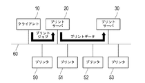
図1は、本発明の第1実施形態にかかるプリントサーバを用いたプリントシステムの全体構成図である。
【0016】
図1に示すように、プリントシステムは、クライアント10と、プリントサーバ20、30と、複数台のプリンタ50〜53とを備え、これらはネットワーク60を介して相互に通信可能に接続されている。ネットワーク60は、イーサネット(登録商標)、トークンリング、FDDI等の規格によりコンピュータやネットワーク機器同士を接続したLANや、LAN同士を専用線で接続したWAN等からなる。
【0017】
クライアント10で作成されたプリントジョブ(各種アプリケーションソフトウェアで作成されたドキュメントデータ、定型業務システムからの帳票データ、あるいは画像処理ソフトウェアなどにより作成された画像データなどの各種データに基づいてプリンタドライバにより作成される)は、プリントサーバ20に送られる。プリントサーバ20は、クライアント10から送られてきたプリントジョブをプリンタ50〜53が画像形成するための画像データ(ビットマップデータ)に変換する。
【0018】
本実施形態において、プリントサーバ20とプリンタ50〜53とは、ネットワーク60を介して接続されているが、本発明は必ずしもこれに限定されるものではなく、ネットワーク60を介することなくたとえばIEEE1394などの規格に従ったインタフェースを介して接続されていてもよい。
【0019】
また、ネットワーク60に接続される機器の種類および台数は、図1に示す例に限定されない。本実施形態において、たとえばプリンタを4台接続しているが、4台に限らず何台接続してもよい。また、プリンタの代わりに、ファクシミリ装置、コピー機、およびそれらの複合機(MFP)などの画像形成装置を用いてもよい。
【0020】
次に、上記各機器の構成について説明するが、各機器で同様の機能を有する部分については、説明の重複を避けるため初回のみその説明を行い、2回目以降はその説明を省略する。
【0021】
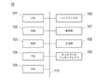
図2は、クライアント10の概略構成を示すブロック図である。クライアント10は、一般的なパーソナルコンピュータである。
【0022】
図2に示すように、クライアント10は、クライアント10全体の制御を行うCPU(Central Processing Unit:中央処理装置)101、各種プログラムやデータを格納するためのROM(Read only Memory)102、作業領域として一時的にプログラムやデータを記憶するためのRAM(Random Access Memory)103、図示しないフレキシブルディスクを読み取るためのフレキシブルディスクドライブ(FDD)104、図示しないCD−ROMを読み取るためのコンパクトディスクドライブ(CDD)105、CPUが実行するプログラムやデータを記憶するためのハードディスク106、各種情報の表示のための液晶ディスプレイなどの表示部107、各種指示の入力のためのキーボードやマウスなどからなる入力部108、および、ネットワーク60に接続するためのLANカードなどのネットワークインタフェース109を含み、これらは信号をやり取りするためのバス110を介して相互に接続されている。
【0023】
ハードディスク106は、プリンタの制御を行うプリンタドライバや、データ送受信用のアプリケーションを記憶することができる。ここで、ハードディスク106にインストールされるプリンタドライバは、プリンタを制御するためのソフトウェアであり、アプリケーションから受け取った文宇や画像のデータをプリンタが解釈することのできるPDL(Page Description Language:ページ記述言語)に変換し、プリントジョブを作成するものである。また、プリンタドライバには、複数ページを縮小して1枚の用紙に印刷する割り付け機能や、プリンタの状態を監視して用紙切れやトナー切れを警告する機能などが備わっている。
【0024】
図3および図4は、それぞれプリントサーバ20、30の概略構成を示すブロック図である。プリントサーバ20、30はプリンタ用のサーバコンピュータである。以下、プリントサーバ20の構成について説明し、プリントサーバ30は、プリントサーバ20と同様の構成であるため説明を省略する。
【0025】
プリントサーバ20は、CPU201、ROM202、RAM203、FDD204、CDD205、ハードディスク206、表示部207、入力部208、ネットワークインタフェース209、および、通信部210を含み、これらは信号をやり取りするためのバス211を介して相互に接続されている。
【0026】
ハードディスク206は、データ送受信用のアプリケーションを記憶することができる。また、ハードディスク206には、外部のクライアント10から受信したプリントジョブにおけるPDLなどで記述されたプリント制御データを解釈し、内部処理可能な形式のデータである中間レコードに変換するプログラムと、作成した中間レコードに基づき画像データを生成するプログラムとが記憶されており、これらプログラムを実行することによりプリントジョブから画像データを生成することができる。
【0027】
通信部210は、たとえばIEEE1394シリアルバスのインタフェースとその制御部分とから構成される。この通信部210は、IEEE1394シリアルバスを介して、各種データを送受信することができる。
【0028】
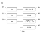
図5は、プリンタ50の概略構成を示すブロック図である。
【0029】
プリンタ50は、プリントサーバ20または30からの指示に基づき、プリントサーバで生成された画像データを用紙上にプリントするものである。以下、プリンタ50の構成について説明し、プリンタ51〜53は、プリンタ50と同様の構成であるため説明を省略する。
【0030】
プリンタ50は、CPU501、ROM502、RAM503、操作パネル部504、印刷部505、ネットワークインタフェース506、および、通信部507を含み、これらは信号をやり取りするためのバス508を介して相互に接続されている。
【0031】
操作パネル部504は、各種情報の表示および各種指示の入力に使用される。印刷部505は、画像データをレーザビーム方式により用紙などの記録材上にプリントする。
【0032】
なお、クライアント10、プリントサーバ20、30、プリンタ50〜53は、上述の構成要素以外の構成要素を含んでいてもよく、あるいは、上述の構成要素のうちの一部が含まれていなくてもよい。
【0033】
次に、図6〜図11を参照して、プリントサーバ20で行われる処理について説明する。図6〜図8は、プリントサーバ20で行われる処理を説明するためのフローチャート、図9〜図11は、プリントジョブまたはプリントデータの流れを模式的に示す図である。なお、図6〜図8のフローチャートにより示されるアルゴリズムは、ハードディスク206などの記憶装置にプログラムとして記憶されており、CPU201により実行される。
【0034】
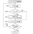
まず、クライアント10により作成されたプリントジョブを受信したか否かを判断する(S101)。プリントジョブを受信していない場合(S101:NO)、受信するまで待機する。プリントジョブを受信した場合(S101:YES、図9参照)、プリントジョブを一旦ハードディスク206に蓄積する(S102)。なお、ステップS102は、プリントスプーラと称されるプリントジョブ要求管理モジュールによって実行される。次いで、プリント実行可能となったプリントジョブをラスタライズする(S103)。具体的には、プリントジョブを、プリンタ50〜53でプリント可能なビットマップ形式の画像データ(以下、「プリントデータ」という)に変換する。
【0035】
続いて、ラスタライズされて得られたプリントデータの各ページのデータサイズに基づき、各ページをプリンタへ転送することが可能なデータ転送速度(ハードディスクからの読出速度)を算出し、図12に示すようなジョブヘッダテーブルを作成する(S104)。図12のジョブヘッダテーブルには、たとえば1000ページの画像を含むプリントジョブに関する情報が記録されており、ここにおいて、各ページに対して、データサイズ(バイト)およびデータ転送速度(PPM)が記録されている。なお、ジョブヘッダテーブルを作成のために必要な情報であるハードディスクからデータを転送するときのビットレートは、たとえば専用アプリケーションを用いて得ることができる。
【0036】
ステップS105では、ジョブヘッダテーブルの内容に基づいて、プリントデータの格納処理が行われる。すなわち、プリントデータをページごとに解析し、プリント時に画像欠損が発生すると判断されなかった場合、当該ページのプリントデータを自機のハードディスク206に格納する。一方、プリント時に画像欠損が発生すると判断された場合、当該ページのプリントデータを他のプリントサーバ30に転送してそのハードディスク306に格納させる(図9参照)。
【0037】
次に、図7を参照して、ステップS105のプリントデータの格納処理について詳細に説明する。
【0038】
まず、プリントサーバ20に接続されており、プリント可能なプリンタ全体(プリンタ群)のプリント速度を取得する(S201)。具体的には、各プリンタのステータス情報を取得し、ステータス情報に基づいてプリント可能であるか否かを判断し、プリント可能であるプリンタのプリント性能(プリント速度を含む)をステータス情報から取得する。たとえば、4台のプリンタ50〜53がプリント可能であり、それぞれが1分間に40枚のプリントが可能な場合(40PPM)、このシステムにおけるプリント速度は、40PPM×4=160PPMとなる。
【0039】
続いて、ステップS104で作成されたジョブヘッダテーブルの解析を行う(S202)。すなわち、ジョブヘッダテーブルの内容に基づいて、プリント速度と処理しようとするページのデータ転送速度との比較を行う。比較を行った結果、注目ページがプリント不可のページであるか否かが判断される(S203)。すなわち、そのページのプリント時に画像欠損が発生するか否かが判断される。ここで、一般的には、データ転送速度がプリント速度よりも低い場合に、注目ページがプリント不可のページであると判断されるが、本発明はかかる判断方法に限定されるものではない。データ転送速度のプリント速度に対する割合が所定の閾値以下の場合に、注目ページがプリント不可のページであると判断されてもよい。
【0040】
たとえば、図12のジョブヘッダテーブルに示されるように、プリントデータのたとえば2ページ目は、そのデータサイズが大きく119PPMの速度でしか送ることができない。この場合、データ転送速度がプリント速度(160PPM)よりも低くなるため、プリント時に画像欠損を生じてしまう。
【0041】
プリント速度と注目ページのデータ転送速度とを比較した結果、注目ページがプリント不可ページでない場合、すなわち、プリント時に画像欠損が発生しないと判断された場合(S203:NO)、自機であるプリントサーバ20のハードディスク206に当該ページを格納する(S205)。一方、注目ページがプリント不可ページであると判断された場合、すなわち、プリント時に画像欠損が発生すると判断された場合(S203:YES)、他のプリントサーバ30のハードディスク306に当該ページを転送して格納する(S204)。
【0042】
次に、プリントジョブの送信時に指定された出力用のプリンタをページごとに示す出力プリンタ情報を、ジョブヘッダテーブルに追加する(S206)。
【0043】
そして、プリントデータの全ページについてステップS202〜S207の処理が終了したか否かが判断される(S207)。全ページの処理が終了していない場合(S207:NO)、ステップS202〜S207の処理を繰り返す。一方、全ページの処理が終了した場合(S207:YES)、ステップS106に進む。
【0044】
図6に示すフローチャートの説明に戻り、ステップS106では、プリントデータの送信処理および他のプリントサーバとの通信処理が行われる。
【0045】
次に、図8を参照して、ステップS106の処理について詳細に説明する。
【0046】
ステップS105でプリントデータを他のプリントサーバ30に転送した場合、ステップS301では、プリントサーバ30に対して、プリント開始準備の通知を送信する。プリントサーバ30にプリント開始準備の通知を送信するのは、プリントサーバ30を占有するためである。これにより、他のジョブがプリントサーバ30で実行されてしまって目的とするプリントデータを同期して出力できなくなることが防止される。
【0047】
そして、ジョブヘッダテーブルの解析を行う(S302)。解析の結果、処理しようとするページがプリント不可のページであるか否かが判断される(S303)。これらの解析(S302)および判断(S303)の内容は、図7のステップS202およびS203と同様であるため、説明を省略する。
【0048】
処理しようとするページがプリント不可のページではないと判断された場合、すなわち、プリント時に画像欠損が発生しないと判断された場合(S303:NO)、当該プリントサーバ20からプリントデータを送信する(S307)。ここで、プリントデータは、プリントジョブの送信時に指定されたプリンタ50〜53に対して、所定ページ数ずつ分割されて並行して送信され(図10参照)、それぞれのプリンタでプリントが実行される。
【0049】
一方、処理しようとするページがプリント不可のページであると判断された場合、すなわち、プリント時に画像欠損が発生すると判断された場合(S303:YES)、当該ページをプリントする予定のプリンタ(たとえばプリンタ53)に対して、プリントデータの送信を終了する(S304)。そして、プリント不可のページのプリントデータを転送した他のプリントサーバ30に対して、プリント開始命令を送信する(S305)。なお、ステップS304およびS305において、プリント不可のページをプリントする予定のプリンタ53に出力するプリントサーバを、プリントサーバ20から他のプリントサーバ30に切り替える処理を行っている間も、他のプリンタ50〜52に対して並行してプリントデータが送信され、それぞれのプリンタでプリントする処理を継続している。
【0050】
その後、プリントサーバ30がプリンタ53にプリントデータを送信してプリントさせる作業が終了したことを通知するためのプリント終了通知を、プリントサーバ30から受信するまで待機する(S306:NO)。なお、この待機中も、他のプリンタ50〜52に対して並行してプリントデータが送信され、それぞれのプリンタでプリントする処理を継続している(図11参照)。
【0051】
プリントサーバ30からプリント終了通知を受信すると(S306:YES)、プリンタ53に関する残りのプリントデータが存在する場合、プリントデータのプリンタ53への送信を再開する(S307)。また、他のプリンタ50〜52に関しても残りのプリントデータが存在する場合、プリントデータのプリンタ50〜52への送信を並行して行う。このとき、プリントデータの流れは、図10に示す状態に戻る。
【0052】
そして、プリントジョブに関する全プリントデータがプリンタへ送信されてプリントが終了したか否かが判断される(S308)。全プリントデータのプリントが終了していない場合(S308:NO)、ステップS302〜S308の処理を繰り返す。一方、全プリントデータのプリントが終了した場合(S308:YES)、他のプリントサーバ30に対して、ステップS101で受信したプリントジョブの実行が終了したことを通知するためのジョブ終了通知を送信し、所定のプリントジョブ終了処理を行う(S309)。
【0053】
次に、図13を参照して、プリントサーバ30で行われる処理について説明する。なお、図13のフローチャートにより示されるアルゴリズムは、ハードディスク306などの記憶装置にプログラムとして記憶されており、CPU301により実行される。
【0054】
以下の説明においては、プリントサーバ20でプリント不可ページであると判断されたページからなるプリントデータが、あらかじめプリントサーバ20から受信され、受信したプリントデータがハードディスク306に格納されている場合について説明する。
【0055】
まず、プリントサーバ20からプリント開始準備通知を受信するまで待機する(S401:NO)。プリントサーバ30は、プリント開始準備通知を受信すると(S401:YES)、プリント開始準備通知と関係のない他のジョブを開始しないように、プリントサーバ30自身を占有する処理を行う(S402)。具体的には、プリントサーバ30を占有するようにステータス情報を変更する。なお、プリントサーバ30は、占有処理を行うことなく、他のジョブを受け付けることも可能である。この場合、本実施形態にかかるジョブによりプリントされた用紙と他のジョブによりプリントされた用紙とが混じることがないように、プリンタにおける両者の用紙の排紙場所を別々に設定することが望ましい。
【0056】
続いて、プリントサーバ20からプリント開始命令を受信するまで待機する(S403:NO)。プリントサーバ30は、プリント開始命令を受信すると(S403:YES)、あらかじめプリントサーバ20から受信されハードディスク306に格納されているプリントデータを、プリンタ53に送信する(S404、図11参照)。プリントサーバ30からプリントデータが送信されるプリンタ53は、ステップS304においてプリントサーバ20からのプリントデータの送信が終了させられたプリンタ、すなわち、プリントサーバ20からのデータ転送先であるプリンタの台数の減少により空いたプリンタである。このとき、プリンタ53は、受信したプリントデータを用紙上にプリントする。
【0057】
そして、プリンタ53に送信したプリントデータのプリントが終了したか否かが判断される(S405)。プリントが終了していない場合(S405:NO)、ステップS404に戻って、ステップS404およびS405の処理を繰り返すことにより、プリンタ53に対してプリントデータの送信を継続する。一方、プリントが終了した場合(S405:YES)、プリントサーバ20に対して、プリントサーバ20から受信したプリントデータをプリンタ53に送信してプリントさせる作業が終了したことを通知するためのプリント終了通知を送信する(S406)。
【0058】
その後、プリントジョブの実行が終了したことを通知するためのジョブ終了通知を、プリントサーバ20から受信するまで待機する(S407:NO)。
【0059】
プリントサーバ30からジョブ終了通知を受信すると(S407:YES)、プリントサーバ30は、他のジョブに備えるために、プリントサーバ30自身を開放する処理を行う(S408)。
【0060】
このように第1実施形態によれば、プリント時に画像欠損が発生すると判断されたページを、他のプリントサーバを介してプリンタに送信させることができる。したがって、必要なデータ転送速度が確保され、プリント速度がデータ転送速度を上回ることを防止するので、プリント時の画像欠損をなくすことができる。しかも、プリントシステム全体で見ればプリントを行うプリンタの台数を減らす必要がないので、プリント作業を効率よく行うことができる。
【0061】
図14は、本発明の第2実施形態にかかるプリントサーバを用いたプリントシステムの全体構成図である。以下、第1実施形態と相違する点を中心に第2実施形態を説明し、共通する点については適宜説明を省略する。
【0062】
図14に示すように、プリントシステムは、クライアント10と、プリントサーバ40と、複数台のプリンタ50〜53とを備え、これらはネットワーク60を介して相互に通信可能に接続されている。本実施形態のプリントシステムでは、1台のプリントサーバ40が用いられる。
【0063】
図15は、プリントサーバ40の概略構成を示すブロック図である。プリントサーバ40は、CPU401、ROM402、RAM403、FDD404、CDD405、第1のハードディスク406a、第2のハードディスク406b、表示部407、入力部408、ネットワークインタフェース409、および、通信部410を含み、これらは信号をやり取りするためのバス411を介して相互に接続されている。
【0064】
このように、本実施形態のプリントサーバ40は、通常使用される第1のハードディスク406aと、第1のハードディスク406aと別個の第2のハードディスク406bとを有している。第2のハードディスク406bは、第1のハードディスク406aよりもデータを高速に読み出し可能であることが望ましく、これにより、プリントデータの送信がより効率よく行われる。
【0065】
次に、図16〜図21を参照して、プリントサーバ40で行われる処理について説明する。図16〜図18は、プリントサーバ40で行われる処理を説明するためのフローチャート、図19〜図21は、プリントジョブまたはプリントデータの流れを模式的に示す図である。なお、図16〜図18のフローチャートにより示されるアルゴリズムは、第1のハードディスク406aなどの記憶装置にプログラムとして記憶されており、CPU401により実行される。
【0066】
クライアント10により作成されたプリントジョブをプリントサーバ40が受信することにより(図19参照)、プリントサーバ40における処理が開始される。図16におけるステップS501〜S504は、図6におけるステップS101〜S104とそれぞれ同様である。
【0067】
ステップS505では、ジョブヘッダテーブルの内容に基づいて、プリントデータの格納処理が行われる。
【0068】
図17に示すように、プリントデータの格納処理では、プリント速度と注目ページのデータ転送速度とを比較した結果、注目ページがプリント不可ページでない場合、すなわち、プリント時に画像欠損が発生しないと判断された場合(S603:NO)、第1のハードディスク406aに当該ページを格納する(S605)。一方、注目ページがプリント不可ページであると判断された場合、すなわち、プリント時に画像欠損が発生すると判断された場合(S603:YES)、第2のハードディスク406bに当該ページを格納する(S604)。なお、図17におけるステップS601〜S603、S606、およびS607は、図7におけるS201〜S203、S206、およびS207とそれぞれ同様である。
【0069】
図16に示すフローチャートの説明に戻り、ステップS506では、第1のハードディスク406aまたは第2のハードディスク406bに格納されたプリントデータの送信処理が行われる。
【0070】
次に、図18を参照して、ステップS506の処理について詳細に説明する。
【0071】
まず、ジョブヘッダテーブルの解析を行う(S701)。解析の結果、処理しようとするページがプリント不可のページであるか否かが判断される(S702)。これらの解析(S701)および判断(S702)のの内容は、図7のステップS202およびS203と同様である。
【0072】
処理しようとするページがプリント不可のページではないと判断された場合、すなわち、プリント時に画像欠損が発生しないと判断された場合(S702:NO)、第1のハードディスク406aから当該ページを読み出して、プリンタに送信する(S704)。本実施形態では、後述するステップS703の切替処理が行われない限り、通常使用される第1のハードディスク406aが、プリントデータの読み出し用ハードディスクとして設定される。ここで、プリントデータは、プリントジョブの送信時に指定されたプリンタ50〜53に対して、所定ページ数ずつ分割されて並行して送信され(図20参照)、それぞれのプリンタでプリントが実行される。
【0073】
一方、処理しようとするページがプリント不可のページであると判断された場合、すなわち、プリント時に画像欠損が発生すると判断された場合(S702:YES)、プリントデータの読み出し用ハードディスクが第2のハードディスク406bに切り替えられ(S703)、第2のハードディスク406bから当該ページを読み出して、たとえばプリンタ53に送信する(S704)。このとき、プリンタ53は、受信したプリントデータを用紙上にプリントする。第2のハードディスク406bから読み出されるページのプリントデータが送信されるプリンタ53は、当該ページの直前のページのプリントデータが送信されたプリンタ、すなわち、プリントデータの読み出し用ハードディスクが切り替えられた結果、第1のハードディスク406aからのデータ転送先であるプリンタの台数の減少により空いたプリンタである。なお、第2のハードディスク406bから読み出されたプリントデータをプリンタ53に送信している間も、第1のハードディスク406aからから読み出されたプリントデータが他のプリンタ50〜52に対して並行して送信され、それぞれのプリンタでプリントする処理を継続している(図21参照)。
【0074】
そして、プリントジョブに関する全プリントデータのプリンタへの送信が終了したか否かが判断される(S705)。全プリントデータの送信が終了していない場合(S705:NO)、ステップS701〜S705の処理を繰り返す。
【0075】
このように第2実施形態によれば、プリント時に画像欠損が発生すると判断されたページを、高速にデータの読み出しが可能な第2のハードディスク406bから読み出してプリンタに送信させることができる。したがって、必要なデータ転送速度が確保され、プリント速度がデータ転送速度を上回ることを防止するので、プリント時の画像欠損をなくすことができる。しかも、プリントシステム全体で見ればプリントを行うプリンタの台数を減らす必要がないので、プリント作業を効率よく行うことができる。
【0076】
本発明は、上記した実施形態のみに限定されるものではなく、特許請求の範囲内において、種々改変することができる。
【0077】
たとえば、上記した実施形態では、画像欠損が生じると判定されたページのプリントデータを、他のプリントサーバ30や第2のハードディスク406bに転送してそこからプリンタヘ転送させる制御について説明したが、かかる制御を行ってもなお画像欠損が生じるおそれがある場合には、プリントシステム全体におけるプリントを実行するプリンタの台数を減らす制御を追加してもよい。この場合、プリントシステム全体におけるプリント速度が若干低下するが、画像欠損の発生をより確実に防止することができる。
【0078】
また、上記した第2実施形態では、プリントデータの格納処理が全ページについて終了した後に、プリントデータのプリンタへの送信処理が行われる場合について説明したが、プリントデータをページごとに解析してハードディスクに格納しながら、ハードディスクからプリントデータを読み出してプリンタへ送信することも可能である。
【0079】
本発明によるプリントサーバにおける図6〜8、13、16〜18の処理を行う各手段、およびプリント方法は、専用のハードウエア回路、またはプログラムされたコンピュータのいずれによっても実現することが可能である。上記プログラムは、例えばフレキシブルディスクやCD−ROMなどのコンピュータ読み取り可能な記録媒体によって提供されてもよいし、インターネット等のネットワークを介してオンラインで提供されてもよい。この場合、コンピュータ読取可能な記録媒体に記録されたプログラムは、通常、ハードディスク等の記憶装置に転送されて記憶される。また、上記プログラムは、単独のアプリケーションソフトとして提供されてもよいし、装置の一機能としてその装置のソフトウェアに組み込まれてもよい。
【0080】
なお、上述した本発明の実施形態には、特許請求の範囲の請求項1〜5に記載した発明以外にも、以下の付記1〜5に示すような発明が含まれる。
【0081】
[付記1] 前記データ転送装置は、第1のハードディスクであり、前記他のデータ転送装置は、前記第1のハードディスクと別個の第2のハードディスクであることを特徴とする請求項1〜4のいずれか1つに記載のプリントプログラム。
【0082】
[付記2] 前記第2のハードディスクは、前記第1のハードディスクよりも高速にデータの読み出しが可能であることを特徴とする付記1に記載のプリントプログラム。
【0083】
[付記3] 前記判定手順において画像欠損が生じると判定されたページのデータを、他のデータ転送装置に転送して当該他のデータ転送装置から画像形成装置ヘ転送させた場合、いずれかの画像形成装置でプリント画像に欠損が生じるか否かを判定する第2の判定手順をさらにコンピュータに実行させ、
前記制御手順において、前記第2の判定手順において画像欠損が生じると判定された場合、データ転送先である画像形成装置の台数を減少させる制御を行うことを特徴とする請求項1〜4、付記1、2のいずれか1つに記載のプリントプログラム。
【0084】
[付記4] 複数の画像形成装置にデータを転送してプリントさせるためのプリント方法であって、
プリント対象のページのデータサイズ、およびプリントサーバ内に設けられデータの蓄積および転送が可能なデータ転送装置のデータ転送能力に基づいて、当該ページのデータ転送速度を演算する演算ステップと、
前記演算ステップにおいて演算されたデータ転送速度と所定台数の画像形成装置におけるプリント速度とを比較し、所定台数の画像形成装置ヘデータを転送したときにプリント画像に欠損が生じるか否かを判定する判定ステップと、
前記判定ステップにおいて画像欠損が生じると判定されたページのデータを、他のデータ転送装置に転送して当該他のデータ転送装置から画像形成装置ヘ転送させる制御を行う制御ステップと、
を有することを特徴とするプリント方法。
【0085】
[付記5] 請求項1に記載のプリントプログラムを記録したコンピュータ読み取り可能な記録媒体。
【0086】
【発明の効果】
以上説明したように、本発明によれば、プリント時に画像欠損が発生すると判断されたページを、他のデータ転送装置を介してプリンタに送信させることができる。したがって、必要なデータ転送速度が確保され、プリント速度がデータ転送速度を上回ることを防止するので、プリント時の画像欠損をなくすことができる。しかも、プリントシステム全体で見ればプリントを行う画像形成装置の台数を減らす必要がないので、プリント作業を効率よく行うことができる。
【図面の簡単な説明】
【図1】 本発明の第1実施形態にかかるプリントサーバを用いたプリントシステムの全体構成図である。
【図2】 クライアントの概略構成を示すブロック図である。
【図3】 プリントサーバの概略構成を示すブロック図である。
【図4】 他のプリントサーバの概略構成を示すブロック図である。
【図5】 プリンタの概略構成を示すブロック図である。
【図6】 プリントサーバで行われる処理を説明するためのフローチャートである。
【図7】 プリントデータの格納処理を説明するためのフローチャートである。
【図8】 プリントデータの送信処理および他のプリントサーバとの通信処理を説明するためのフローチャートである。
【図9】 プリントジョブおよびプリントデータの流れを模式的に示す図である。
【図10】 プリントデータの流れを模式的に示す図である。
【図11】 プリントデータの流れを模式的に示す図である。
【図12】 ジョブヘッダテーブルの一例を示す図である。
【図13】 他のプリントサーバで行われる処理を説明するためのフローチャートである。
【図14】 本発明の第2実施形態にかかるプリントサーバを用いたプリントシステムの全体構成図である。
【図15】 第2実施形態のプリントサーバの概略構成を示すブロック図である。
【図16】 第2実施形態のプリントサーバで行われる処理を説明するためのフローチャートである。
【図17】 プリントデータの格納処理を説明するためのフローチャートである。
【図18】 プリントデータの送信処理を説明するためのフローチャートである。
【図19】 プリントジョブの流れを模式的に示す図である。
【図20】 プリントデータの流れを模式的に示す図である。
【図21】 プリントデータの流れを模式的に示す図である。
【符号の説明】
10…クライアント、
20…プリントサーバ、
201…CPU、
202…ROM、
203…RAM、
204…FDD、
205…CDD、
206…ハードディスク、
207…表示部、
208…入力部、
209…ネットワークインタフェース、
210…通信部、
211…バス、
30…他のプリントサーバ、
306…ハードディスク、
40…プリントサーバ、
406a…第1のハードディスク、
406b…第2のハードディスク、
50〜53…プリンタ、
60…ネットワーク。[0001]
BACKGROUND OF THE INVENTION
The present invention relates to a print server and a printing method, and more particularly to a print program and a print server that perform printing using a plurality of image forming apparatuses in order to increase printing efficiency.
[0002]
[Prior art]
There is an office service assistance service store that receives print data from a customer via a recording medium such as a flexible disk or a network, outputs the print data to a sheet by an image forming apparatus such as a printer, and provides it to the customer. When a large amount of paper is output in such a store, the work time can be shortened by printing out in parallel using a plurality of printers. Printing in parallel with a plurality of printers in this way is called distributed printing (Cluster Printing). In distributed printing, a print server that manages a plurality of printers is used. For example, assume that a distributed printing system is constructed by connecting four printers to a print server. For example, when this distributed printing system accepts a job for printing 1000 pages, the job is divided into 1 to 250 pages, 251 to 500 pages, 501 to 750 pages, and 751 to 1000 pages. In parallel, 250 pages are printed. As a result, the time until printing is completed is ¼ that when processing is performed by one printer.
[0003]
[Problems to be solved by the invention]
If the printer used in the distributed printing system is not equipped with a sufficient memory for storing print data, the print server needs to transfer the print data in accordance with the print speed of the printer.
[0004]
However, in the above-described distributed printing system, the total printing speed increases in proportion to the number of connected printers, so the data transfer speed from the print server also needs to be high according to the number of printers. Here, if the print speed is increased by configuring a plurality of printer groups, the data transfer speed to the printer may be lower than the printer print speed as a result (in this specification, the unit of the data transfer speed). The same PPM (page per minute) is used as the unit of print speed (the number of pages of image data that can be processed per minute).
[0005]
In addition, since there is an upper limit on the reading speed of the hard disk, which is an image storage device of the print server, the data transfer speed (PPM) from the print server is lower as image data (one page) with a larger data size is smaller. The smaller the image data (for one page), the higher. Here, when the data size of the image data is large, the data transfer speed (PPM) from the print server is low, and as a result, the data transfer speed to the printer may be lower than the print speed of the printer.
[0006]
Thus, the larger the data size of the image data and the greater the number of data transfer destination printers, the higher the possibility that the data transfer speed to the printer will be lower than the printer print speed. As a result, there is a problem that image data transfer for one page cannot be completed during printing of one page, and there is a possibility that the printed image may be lost.
[0007]
SUMMARY An advantage of some aspects of the invention is that it provides a print program and a print server that can prevent image loss when an image is formed by a plurality of image forming apparatuses. It is to be.
[0008]
[Means for Solving the Problems]
The object of the present invention is achieved by the following means.
[0009]
(1) A print program for transferring data to a plurality of image forming apparatuses for printing, the data size of a page to be printed, and a data transfer apparatus provided in a print server and capable of storing and transferring data The calculation procedure for calculating the data transfer speed of the page based on the data transfer capability of the page is compared with the data transfer speed calculated in the calculation procedure and the print speed in the predetermined number of image forming apparatuses. A determination procedure for determining whether or not a defect occurs in a print image when data is transferred to the forming apparatus, and transferring data of a page determined to have an image defect in the determination procedure to another data transfer apparatus A control procedure for performing control to transfer data from the other data transfer device to the image forming device. Because print program.
[0010]
(2) In the control procedure, the number of image forming apparatuses that are data transfer destinations from the data transfer apparatus is decreased, and the page data determined to cause image loss is transferred from the other data transfer apparatus to the number of the data. The print program according to (1), wherein control is performed to transfer the image data to an image forming apparatus that is free due to a decrease in image data.
[0011]
(3) In the above (1) or (2), the other data transfer device is provided in the plurality of image forming apparatuses and another print server capable of communicating with the print server. Print program.
[0012]
(4) The print program according to (1) or (2), wherein the other data transfer device is provided in the print server.
[0013]
(5) A print server capable of transferring data to a plurality of image forming apparatuses, the data size of a page to be printed, and a data transfer apparatus provided in the print server and capable of storing and transferring data Based on the data transfer capability, the calculation means for calculating the data transfer speed of the page, the data transfer speed calculated by the calculation means and the print speed in the predetermined number of image forming apparatuses are compared, and the predetermined number of image formation Determining means for determining whether or not a defect occurs in the print image when the data is transferred to the apparatus, and transferring the page data determined by the determining means to cause the image defect to another data transfer apparatus And a control means for performing control for transferring data from another data transfer apparatus to the image forming apparatus.
[0014]
DETAILED DESCRIPTION OF THE INVENTION
Embodiments of the present invention will be described below with reference to the drawings.
[0015]
FIG. 1 is an overall configuration diagram of a print system using a print server according to the first embodiment of the present invention.
[0016]
As shown in FIG. 1, the print system includes a
[0017]
Print jobs created by the client 10 (created by the printer driver based on various data such as document data created by various application software, form data from routine business systems, or image data created by image processing software, etc. Is sent to the
[0018]
In the present embodiment, the
[0019]
Further, the types and the number of devices connected to the
[0020]
Next, the configuration of each device will be described, but portions having similar functions in each device will be described only for the first time in order to avoid duplication of description, and description thereof will be omitted from the second time onward.
[0021]
FIG. 2 is a block diagram illustrating a schematic configuration of the
[0022]
As shown in FIG. 2, the
[0023]
The
[0024]
3 and 4 are block diagrams showing schematic configurations of the
[0025]
The
[0026]
The
[0027]
The
[0028]
FIG. 5 is a block diagram illustrating a schematic configuration of the
[0029]
The
[0030]
The
[0031]
The
[0032]
The
[0033]
Next, processing performed in the
[0034]
First, it is determined whether or not a print job created by the
[0035]
Subsequently, based on the data size of each page of the print data obtained by rasterization, a data transfer speed (reading speed from the hard disk) capable of transferring each page to the printer is calculated, as shown in FIG. A new job header table is created (S104). In the job header table of FIG. 12, information relating to a print job including, for example, an image of 1000 pages is recorded. Here, the data size (bytes) and the data transfer rate (PPM) are recorded for each page. ing. The bit rate for transferring data from the hard disk, which is information necessary for creating the job header table, can be obtained by using a dedicated application, for example.
[0036]
In step S105, print data storage processing is performed based on the contents of the job header table. That is, the print data is analyzed for each page, and if it is not determined that an image loss occurs during printing, the print data of the page is stored in the
[0037]
Next, the print data storing process in step S105 will be described in detail with reference to FIG.
[0038]
First, the print speed of the entire printer (printer group) connected to the
[0039]
Subsequently, the job header table created in step S104 is analyzed (S202). That is, the print speed is compared with the data transfer speed of the page to be processed based on the contents of the job header table. As a result of the comparison, it is determined whether or not the page of interest is a page that cannot be printed (S203). That is, it is determined whether or not an image defect occurs when the page is printed. Here, generally, when the data transfer speed is lower than the print speed, it is determined that the page of interest is a non-printable page. However, the present invention is not limited to such a determination method. When the ratio of the data transfer speed to the print speed is equal to or less than a predetermined threshold value, it may be determined that the page of interest is a non-printable page.
[0040]
For example, as shown in the job header table of FIG. 12, the second page of print data, for example, has a large data size and can only be sent at a speed of 119 PPM. In this case, since the data transfer speed is lower than the print speed (160 PPM), image loss occurs during printing.
[0041]
As a result of comparing the print speed with the data transfer speed of the page of interest, if it is determined that the page of interest is not a non-printable page, that is, it is determined that no image loss occurs during printing (S203: NO), the print server as its own device The page is stored in the 20 hard disk 206 (S205). On the other hand, when it is determined that the page of interest is a non-printable page, that is, when it is determined that an image loss occurs during printing (S203: YES), the page is transferred to the
[0042]
Next, output printer information indicating, for each page, the output printer designated when the print job is transmitted is added to the job header table (S206).
[0043]
Then, it is determined whether or not the processing of steps S202 to S207 has been completed for all pages of the print data (S207). If all the pages have not been processed (S207: NO), the processes in steps S202 to S207 are repeated. On the other hand, if all pages have been processed (S207: YES), the process proceeds to step S106.
[0044]
Returning to the description of the flowchart shown in FIG. 6, in step S106, print data transmission processing and communication processing with another print server are performed.
[0045]
Next, the process of step S106 will be described in detail with reference to FIG.
[0046]
When the print data is transferred to another
[0047]
Then, the job header table is analyzed (S302). As a result of the analysis, it is determined whether or not the page to be processed is a non-printable page (S303). The contents of the analysis (S302) and determination (S303) are the same as those in steps S202 and S203 in FIG.
[0048]
When it is determined that the page to be processed is not a non-printable page, that is, when it is determined that no image loss occurs during printing (S303: NO), print data is transmitted from the print server 20 (S307). ). Here, the print data is divided by a predetermined number of pages and transmitted in parallel to the
[0049]
On the other hand, when it is determined that the page to be processed is a non-printable page, that is, when it is determined that an image loss occurs during printing (S303: YES), a printer (for example, a printer) scheduled to print the page 53), the transmission of the print data is terminated (S304). Then, a print start command is transmitted to the
[0050]
After that, the
[0051]
When a print end notification is received from the print server 30 (S306: YES), if there is remaining print data related to the
[0052]
Then, it is determined whether all print data relating to the print job has been transmitted to the printer and printing has ended (S308). If printing of all print data has not been completed (S308: NO), the processing in steps S302 to S308 is repeated. On the other hand, when printing of all print data is completed (S308: YES), a job completion notification for notifying that the execution of the print job received in step S101 is completed is transmitted to the
[0053]
Next, processing performed in the
[0054]
In the following description, a case will be described in which print data composed of pages determined to be non-printable pages by the
[0055]
First, it waits until a print start preparation notification is received from the print server 20 (S401: NO). When the
[0056]
Then, it waits until a print start command is received from the print server 20 (S403: NO). When the
[0057]
Then, it is determined whether printing of the print data transmitted to the
[0058]
Thereafter, it waits until it receives from the print server 20 a job end notification for notifying that the execution of the print job has ended (S407: NO).
[0059]
When a job end notification is received from the print server 30 (S407: YES), the
[0060]
As described above, according to the first embodiment, a page determined to have an image loss during printing can be transmitted to the printer via another print server. Therefore, the necessary data transfer speed is ensured and the print speed is prevented from exceeding the data transfer speed, so that image loss during printing can be eliminated. In addition, since it is not necessary to reduce the number of printers that perform printing as viewed in the entire printing system, printing can be performed efficiently.
[0061]
FIG. 14 is an overall configuration diagram of a print system using a print server according to the second embodiment of the present invention. Hereinafter, the second embodiment will be described with a focus on differences from the first embodiment, and description of common points will be omitted as appropriate.
[0062]
As shown in FIG. 14, the print system includes a
[0063]
FIG. 15 is a block diagram illustrating a schematic configuration of the
[0064]
As described above, the
[0065]
Next, processing performed by the
[0066]
When the
[0067]
In step S505, print data storage processing is performed based on the contents of the job header table.
[0068]
As shown in FIG. 17, in the print data storage process, as a result of comparing the print speed with the data transfer speed of the page of interest, it is determined that the page of interest is not a non-printable page, that is, no image loss occurs during printing. If this happens (S603: NO), the page is stored in the first
[0069]
Returning to the description of the flowchart shown in FIG. 16, in step S506, transmission processing of print data stored in the first
[0070]
Next, the process of step S506 will be described in detail with reference to FIG.
[0071]
First, the job header table is analyzed (S701). As a result of the analysis, it is determined whether or not the page to be processed is a non-printable page (S702). The contents of these analysis (S701) and determination (S702) are the same as steps S202 and S203 in FIG.
[0072]
When it is determined that the page to be processed is not a non-printable page, that is, when it is determined that no image loss occurs during printing (S702: NO), the page is read from the first
[0073]
On the other hand, if it is determined that the page to be processed is a non-printable page, that is, if it is determined that an image loss occurs during printing (S702: YES), the print data reading hard disk is the second hard disk. The page is switched to 406b (S703), and the page is read from the second
[0074]
Then, it is determined whether transmission of all print data relating to the print job to the printer has been completed (S705). If transmission of all print data has not been completed (S705: NO), the processing of steps S701 to S705 is repeated.
[0075]
As described above, according to the second embodiment, a page determined to have an image defect during printing can be read from the second
[0076]
The present invention is not limited to the above-described embodiments, and various modifications can be made within the scope of the claims.
[0077]
For example, in the above-described embodiment, the control for transferring the print data of the page determined to have image loss to the
[0078]
In the second embodiment described above, a case has been described in which print data storage processing is completed for all pages, and then print data is transmitted to a printer. It is also possible to read the print data from the hard disk and transmit it to the printer while storing it in the printer.
[0079]
Each of the means for performing the processes of FIGS. 6 to 8, 13, and 16 to 18 and the printing method in the print server according to the present invention can be realized by either a dedicated hardware circuit or a programmed computer. . The program may be provided by a computer-readable recording medium such as a flexible disk or a CD-ROM, or may be provided online via a network such as the Internet. In this case, the program recorded on the computer-readable recording medium is usually transferred to and stored in a storage device such as a hard disk. The program may be provided as a single application software, or may be incorporated into the software of the device as one function of the device.
[0080]
In addition to the inventions described in
[0081]
[Appendix 1] The data transfer device is a first hard disk, and the other data transfer device is a second hard disk separate from the first hard disk. The print program as described in any one.
[0082]
[Supplementary Note 2] The print program according to
[0083]
[Supplementary Note 3] When data of a page determined to have image loss in the determination procedure is transferred to another data transfer apparatus and transferred from the other data transfer apparatus to the image forming apparatus, any image is displayed. Causing the computer to further execute a second determination procedure for determining whether or not the printed image is defective in the forming apparatus;
5. The control according to
[0084]
[Supplementary Note 4] A printing method for transferring data to a plurality of image forming apparatuses for printing.
A calculation step for calculating the data transfer speed of the page based on the data size of the page to be printed and the data transfer capability of the data transfer device provided in the print server and capable of storing and transferring data;
Judgment that compares the data transfer speed calculated in the calculation step with the print speed of a predetermined number of image forming apparatuses to determine whether or not a print image is defective when data is transferred to the predetermined number of image forming apparatuses Steps,
A control step for performing control to transfer the data of the page determined to have image loss in the determination step to another data transfer device and to transfer the data from the other data transfer device to the image forming device;
A printing method characterized by comprising:
[0085]
[Appendix 5] A computer-readable recording medium in which the print program according to
[0086]
【The invention's effect】
As described above, according to the present invention, it is possible to transmit a page determined to have an image loss during printing to a printer via another data transfer device. Therefore, the necessary data transfer speed is ensured and the print speed is prevented from exceeding the data transfer speed, so that image loss during printing can be eliminated. In addition, since it is not necessary to reduce the number of image forming apparatuses that perform printing as viewed in the entire printing system, the printing operation can be performed efficiently.
[Brief description of the drawings]
FIG. 1 is an overall configuration diagram of a print system using a print server according to a first embodiment of the present invention.
FIG. 2 is a block diagram showing a schematic configuration of a client.
FIG. 3 is a block diagram illustrating a schematic configuration of a print server.
FIG. 4 is a block diagram illustrating a schematic configuration of another print server.
FIG. 5 is a block diagram illustrating a schematic configuration of a printer.
FIG. 6 is a flowchart for explaining processing performed in the print server.
FIG. 7 is a flowchart for explaining print data storage processing;
FIG. 8 is a flowchart for explaining print data transmission processing and communication processing with another print server.
FIG. 9 is a diagram schematically illustrating the flow of a print job and print data.
FIG. 10 is a diagram schematically illustrating the flow of print data.
FIG. 11 is a diagram schematically illustrating the flow of print data.
FIG. 12 is a diagram illustrating an example of a job header table.
FIG. 13 is a flowchart for explaining processing performed in another print server;
FIG. 14 is an overall configuration diagram of a print system using a print server according to a second embodiment of the present invention.
FIG. 15 is a block diagram illustrating a schematic configuration of a print server according to a second embodiment.
FIG. 16 is a flowchart for explaining processing performed in the print server according to the second embodiment;
FIG. 17 is a flowchart for explaining print data storage processing;
FIG. 18 is a flowchart for explaining print data transmission processing;
FIG. 19 is a diagram schematically illustrating the flow of a print job.
FIG. 20 is a diagram schematically illustrating the flow of print data.
FIG. 21 is a diagram schematically illustrating the flow of print data.
[Explanation of symbols]
10 ... Client,
20 ... print server,
201 ... CPU,
202 ... ROM,
203 ... RAM,
204 ... FDD,
205 ... CDD,
206: Hard disk,
207 ... display section,
208 ... input section,
209 ... Network interface,
210 ... communication section,
211 ... Bus
30 ... Other print servers,
306: Hard disk,
40 ... print server,
406a ... first hard disk,
406b ... second hard disk,
50-53 ... printer,
60 ... Network.
Claims (10)
プリント対象のページのデータサイズ、およびプリントサーバ内に設けられデータの蓄積および転送が可能なデータ転送装置のデータ転送能力に基づいて、当該ページのデータ転送速度を演算する演算手順と、
前記演算手順において演算されたデータ転送速度と所定台数の画像形成装置におけるプリント速度とを比較し、所定台数の画像形成装置ヘデータを転送したときにプリント画像に欠損が生じるか否かを判定する判定手順と、
前記判定手順において画像欠損が生じると判定されたページのデータを、他のデータ転送装置に転送して当該他のデータ転送装置から画像形成装置ヘ転送させる制御を行う制御手順と、
をコンピュータに実行させるためのプリントプログラム。A print program for transferring and printing data to a plurality of image forming apparatuses,
A calculation procedure for calculating the data transfer rate of the page based on the data size of the page to be printed and the data transfer capability of the data transfer device provided in the print server and capable of storing and transferring data;
Judgment that compares the data transfer speed calculated in the calculation procedure with the print speed of a predetermined number of image forming apparatuses and determines whether or not a defect occurs in the print image when data is transferred to the predetermined number of image forming apparatuses Procedure and
A control procedure for performing control to transfer the data of the page determined to have image loss in the determination procedure to another data transfer device and to transfer the data from the other data transfer device to the image forming device;
A print program that causes a computer to execute.
プリント対象のページのデータサイズ、およびプリントサーバ内に設けられデータの蓄積および転送が可能なデータ転送装置のデータ転送能力に基づいて、当該ページのデータ転送速度を演算する演算手段と、
前記演算手段により演算されたデータ転送速度と所定台数の画像形成装置におけるプリント速度とを比較し、所定台数の画像形成装置ヘデータを転送したときにプリント画像に欠損が生じるか否かを判定する判定手段と、
前記判定手段により画像欠損が生じると判定されたページのデータを、他のデータ転送装置に転送して当該他のデータ転送装置から画像形成装置ヘ転送させる制御を行う制御手段と、
を有することを特徴とするプリントサーバ。A print server capable of transferring data to a plurality of image forming apparatuses,
A computing means for computing the data transfer rate of the page based on the data size of the page to be printed and the data transfer capability of the data transfer device provided in the print server and capable of storing and transferring data;
Judgment that compares the data transfer speed calculated by the calculation means with the print speed of a predetermined number of image forming apparatuses and determines whether or not the printed image is defective when data is transferred to the predetermined number of image forming apparatuses Means,
Control means for performing control to transfer the data of the page determined to have image loss by the determination means to another data transfer apparatus and to transfer the data from the other data transfer apparatus to the image forming apparatus;
A print server.
前記制御手順において、前記第2の判定手順において画像欠損が生じると判定された場合、データ転送先である画像形成装置の台数を減少させる制御を行うことを特徴とする請求項1〜4、6、7のいずれか1つに記載のプリントプログラム。When data of a page determined to have image loss in the determination procedure is transferred to another data transfer apparatus and transferred from the other data transfer apparatus to the image forming apparatus, printing is performed by any of the image forming apparatuses. Causing the computer to further execute a second determination procedure for determining whether or not a defect occurs in the image;
7. The control according to claim 1, wherein, in the control procedure, when it is determined in the second determination procedure that an image defect occurs, control is performed to reduce the number of image forming apparatuses that are data transfer destinations. , 7. The print program according to any one of 7 above.
プリント対象のページのデータサイズ、およびプリントサーバ内に設けられデータの蓄積および転送が可能なデータ転送装置のデータ転送能力に基づいて、当該ページのデータ転送速度を演算する演算ステップと、
前記演算ステップにおいて演算されたデータ転送速度と所定台数の画像形成装置におけるプリント速度とを比較し、所定台数の画像形成装置ヘデータを転送したときにプリント画像に欠損が生じるか否かを判定する判定ステップと、
前記判定ステップにおいて画像欠損が生じると判定されたページのデータを、他のデータ転送装置に転送して当該他のデータ転送装置から画像形成装置ヘ転送させる制御を行う制御ステップと、
を有することを特徴とするプリント方法。A printing method for transferring and printing data to a plurality of image forming apparatuses,
A calculation step for calculating the data transfer speed of the page based on the data size of the page to be printed and the data transfer capability of the data transfer device provided in the print server and capable of storing and transferring data;
Judgment that compares the data transfer speed calculated in the calculation step with the print speed of a predetermined number of image forming apparatuses to determine whether or not a print image is defective when data is transferred to the predetermined number of image forming apparatuses Steps,
A control step for performing control to transfer the data of the page determined to have image loss in the determination step to another data transfer device and to transfer the data from the other data transfer device to the image forming device;
A printing method characterized by comprising:
Priority Applications (2)
| Application Number | Priority Date | Filing Date | Title |
|---|---|---|---|
| JP2002126899A JP4029656B2 (en) | 2002-04-26 | 2002-04-26 | Print program and print server |
| US10/422,780 US7760376B2 (en) | 2002-04-26 | 2003-04-25 | Printing method, printing system, print server, and computer readable recording medium on which printing program is recorded |
Applications Claiming Priority (1)
| Application Number | Priority Date | Filing Date | Title |
|---|---|---|---|
| JP2002126899A JP4029656B2 (en) | 2002-04-26 | 2002-04-26 | Print program and print server |
Publications (3)
| Publication Number | Publication Date |
|---|---|
| JP2003323278A JP2003323278A (en) | 2003-11-14 |
| JP2003323278A5 JP2003323278A5 (en) | 2005-08-25 |
| JP4029656B2 true JP4029656B2 (en) | 2008-01-09 |
Family
ID=29243819
Family Applications (1)
| Application Number | Title | Priority Date | Filing Date |
|---|---|---|---|
| JP2002126899A Expired - Fee Related JP4029656B2 (en) | 2002-04-26 | 2002-04-26 | Print program and print server |
Country Status (2)
| Country | Link |
|---|---|
| US (1) | US7760376B2 (en) |
| JP (1) | JP4029656B2 (en) |
Families Citing this family (8)
| Publication number | Priority date | Publication date | Assignee | Title |
|---|---|---|---|---|
| JP3879501B2 (en) * | 2001-12-07 | 2007-02-14 | コニカミノルタビジネステクノロジーズ株式会社 | PRINT SERVER, PRINT SYSTEM, PRINT METHOD, PRINT PROGRAM, AND COMPUTER-READABLE RECORDING MEDIUM CONTAINING PRINT PROGRAM |
| US6623190B1 (en) * | 2002-05-03 | 2003-09-23 | Hewlett-Packard Development Company, L.P. | Methods and apparatus for managing a print job among a processor, an image producing device, and an external storage device |
| CN1728761A (en) * | 2004-06-16 | 2006-02-01 | 株式会社理光 | Apparatus, method, and program for image processing capable of enhancing usability of image data |
| JP4164483B2 (en) * | 2004-09-09 | 2008-10-15 | キヤノン株式会社 | Image processing system, image processing apparatus, control method, program, and storage medium |
| US20070268504A1 (en) * | 2006-05-16 | 2007-11-22 | Proexecute, Llc | Enhanced imaging spooler |
| JP4371148B2 (en) * | 2007-04-11 | 2009-11-25 | コニカミノルタビジネステクノロジーズ株式会社 | Information processing apparatus, information processing method, and program |
| JP5826154B2 (en) | 2012-11-29 | 2015-12-02 | 京セラドキュメントソリューションズ株式会社 | Image forming apparatus |
| JP7155637B2 (en) * | 2018-06-13 | 2022-10-19 | 富士フイルムビジネスイノベーション株式会社 | Integrated Manufacturing Management System for Printed Matter, Integrated Manufacturing Management Device and Program |
Family Cites Families (14)
| Publication number | Priority date | Publication date | Assignee | Title |
|---|---|---|---|---|
| US7046391B1 (en) * | 1995-08-07 | 2006-05-16 | Electronics For Imaging, Inc. | Method and apparatus for providing a color-balanced multiple print engine |
| US6552813B2 (en) * | 1996-06-11 | 2003-04-22 | Sun Microsystems, Inc. | Directing print jobs in a network printing system |
| US6952276B2 (en) * | 1997-01-27 | 2005-10-04 | Seiko Epson Corporation | Printer detecting data precisely in response to change in data transmission speed |
| JP3320342B2 (en) * | 1997-09-12 | 2002-09-03 | インターナショナル・ビジネス・マシーンズ・コーポレーション | Method for causing printer system to execute printing, print execution method, computer, and printer system |
| JPH11237964A (en) | 1998-02-19 | 1999-08-31 | Ricoh Co Ltd | Printer printing system |
| JPH11348351A (en) * | 1998-06-09 | 1999-12-21 | Canon Inc | Image-processing system, image-forming apparatus, method for processing image, and computer readable memory |
| CN1145876C (en) * | 1999-03-29 | 2004-04-14 | 精工爱普生株式会社 | Network system and network interface card |
| JP2000318268A (en) | 1999-05-10 | 2000-11-21 | Ricoh Co Ltd | Printer system, parallel printing method for printing system and memory medium storing program |
| US6781711B1 (en) * | 2000-05-15 | 2004-08-24 | International Business Machines Corporation | Method and system for efficient transmittal and presentation of complex images |
| JP4532795B2 (en) * | 2000-09-13 | 2010-08-25 | キヤノン株式会社 | Image output device, image output device control method, image output system, and storage medium |
| US7110129B2 (en) * | 2001-01-26 | 2006-09-19 | International Business Machines Corporation | Method, system, and program for responding to an acknowledgement request from a printer driver |
| JP2002297346A (en) * | 2001-03-29 | 2002-10-11 | Ricoh Co Ltd | Sbc-adadtive printer output system and method, program for realizing the method, and recording medium for the recording program |
| US7113301B2 (en) * | 2001-10-31 | 2006-09-26 | Hewlett-Packard Development Company, L.P. | System and method for automated access of a network page |
| US6943905B2 (en) * | 2001-12-20 | 2005-09-13 | Sharp Laboratories Of America, Inc. | Virtual print driver system and method |
-
2002
- 2002-04-26 JP JP2002126899A patent/JP4029656B2/en not_active Expired - Fee Related
-
2003
- 2003-04-25 US US10/422,780 patent/US7760376B2/en not_active Expired - Fee Related
Also Published As
| Publication number | Publication date |
|---|---|
| US20030202206A1 (en) | 2003-10-30 |
| US7760376B2 (en) | 2010-07-20 |
| JP2003323278A (en) | 2003-11-14 |
Similar Documents
| Publication | Publication Date | Title |
|---|---|---|
| JP4029656B2 (en) | Print program and print server | |
| US20120069398A1 (en) | Printing system and printing device | |
| JP3879501B2 (en) | PRINT SERVER, PRINT SYSTEM, PRINT METHOD, PRINT PROGRAM, AND COMPUTER-READABLE RECORDING MEDIUM CONTAINING PRINT PROGRAM | |
| CN102790839A (en) | Image forming apparatus | |
| US8451465B2 (en) | Automatic device-independent adaptation of page description language data streams | |
| JP2000035870A (en) | Print system and printer | |
| JP4007084B2 (en) | Print program | |
| JP2007055115A (en) | Printer and method for developing interruption job memory | |
| JP3230984B2 (en) | Image processing system | |
| JP2006268110A (en) | Printing job processing program and its method and distribution/delivery system | |
| US7352482B2 (en) | Apparatus and method for processing data and printing the same, and recording medium | |
| JP2004188865A (en) | Image forming device and program | |
| JP4029672B2 (en) | Print program, print server, and printing method | |
| JP3779833B2 (en) | Printer system, printer method, and terminal device | |
| JPH10283130A (en) | Device, method for controlling printer and record medium | |
| JP3332757B2 (en) | Print data output device and print data output method | |
| JP2004054658A (en) | Printing system | |
| JP5062750B2 (en) | Image forming apparatus | |
| JP5868298B2 (en) | Image forming system, image forming apparatus, and program | |
| JP2007276269A (en) | Printer, and load distribution controlling method | |
| JP4035304B2 (en) | Digital information output system | |
| JP2007011694A (en) | Image recording system, image recording method and image recording device | |
| JP2007025977A (en) | Print support system, print support program and print support method | |
| JP4052122B2 (en) | Print program and print server | |
| JP2000315141A (en) | Printer and method for managing memory of recording medium and printer |
Legal Events
| Date | Code | Title | Description |
|---|---|---|---|
| A711 | Notification of change in applicant |
Free format text: JAPANESE INTERMEDIATE CODE: A712 Effective date: 20040423 |
|
| A521 | Request for written amendment filed |
Free format text: JAPANESE INTERMEDIATE CODE: A523 Effective date: 20050215 |
|
| A621 | Written request for application examination |
Free format text: JAPANESE INTERMEDIATE CODE: A621 Effective date: 20050215 |
|
| RD03 | Notification of appointment of power of attorney |
Free format text: JAPANESE INTERMEDIATE CODE: A7423 Effective date: 20050215 |
|
| A977 | Report on retrieval |
Free format text: JAPANESE INTERMEDIATE CODE: A971007 Effective date: 20070914 |
|
| TRDD | Decision of grant or rejection written | ||
| A01 | Written decision to grant a patent or to grant a registration (utility model) |
Free format text: JAPANESE INTERMEDIATE CODE: A01 Effective date: 20070925 |
|
| A61 | First payment of annual fees (during grant procedure) |
Free format text: JAPANESE INTERMEDIATE CODE: A61 Effective date: 20071008 |
|
| R150 | Certificate of patent or registration of utility model |
Free format text: JAPANESE INTERMEDIATE CODE: R150 |
|
| FPAY | Renewal fee payment (event date is renewal date of database) |
Free format text: PAYMENT UNTIL: 20101026 Year of fee payment: 3 |
|
| FPAY | Renewal fee payment (event date is renewal date of database) |
Free format text: PAYMENT UNTIL: 20111026 Year of fee payment: 4 |
|
| FPAY | Renewal fee payment (event date is renewal date of database) |
Free format text: PAYMENT UNTIL: 20121026 Year of fee payment: 5 |
|
| FPAY | Renewal fee payment (event date is renewal date of database) |
Free format text: PAYMENT UNTIL: 20121026 Year of fee payment: 5 |
|
| FPAY | Renewal fee payment (event date is renewal date of database) |
Free format text: PAYMENT UNTIL: 20131026 Year of fee payment: 6 |
|
| LAPS | Cancellation because of no payment of annual fees |