JP2006076080A - Coating equipment - Google Patents
Coating equipment Download PDFInfo
- Publication number
- JP2006076080A JP2006076080A JP2004261478A JP2004261478A JP2006076080A JP 2006076080 A JP2006076080 A JP 2006076080A JP 2004261478 A JP2004261478 A JP 2004261478A JP 2004261478 A JP2004261478 A JP 2004261478A JP 2006076080 A JP2006076080 A JP 2006076080A
- Authority
- JP
- Japan
- Prior art keywords
- varnish
- cylinder
- film forming
- forming cylinder
- rubber
- Prior art date
- Legal status (The legal status is an assumption and is not a legal conclusion. Google has not performed a legal analysis and makes no representation as to the accuracy of the status listed.)
- Granted
Links
Images

Abstract
Description
本発明は、枚葉輪転印刷機の印刷ユニットと排紙装置との間、または独立したニス塗り機内等に設けられ、印刷後の紙の印刷面にニスを塗布するコーティング装置に関するものである。 The present invention relates to a coating apparatus that is provided between a printing unit of a sheet-fed rotary printing press and a paper discharge device, or in an independent varnishing machine, and applies a varnish to a printed surface of paper after printing.
従来のコーティング装置は、最終の印刷ユニットの圧胴に対向するゴム圧胴と、印刷された紙の裏面をコーティングする第1のニスコーティング手段と、印刷された紙の表面をコーティングする第2のニスコーティング手段とから構成されている。第1のニスコーティング手段は、ゴム圧胴に対向する第1のニス膜形成胴と、この第1のニス膜形成胴に対向するアニロックスローラと、このアニロックスローラにニスを供給するチャンバーコータとからなる。したがって、チャンバーコータからアニロックスローラに供給されたニスは、第1のニス膜形成胴を介してゴム圧胴の周面に転移される。第2のニスコーティング手段は、ゴム圧胴に対向するゴム胴と、このゴム胴と対向する第2のニス膜形成胴と、この第2のニス膜形成胴に対向するアニロックスローラと、このアニロックスローラにニスを供給するチャンバーコータとからなる。したがって、チャンバーコータからアニロックスローラに供給されたニスは、第2のニス膜形成胴を介してゴム胴に転移され、このゴム胴とゴム圧胴の対向点を通過する印刷された紙の表面にコーティングされる。このゴム胴とゴム圧胴の対向点を紙が通過するときに、ゴム胴の印圧によって、第1のニスコーティング手段の第1のニス膜形成胴からゴム圧胴の周面に転移されたニスが、印刷された紙の裏面にコーティングされる(例えば、特許文献1参照)。なお、本出願人は、本明細書に記載した先行技術文献情報で特定される先行技術文献以外には、本発明に密接に関連する先行技術文献を出願時までに見付け出すことはできなかった。
上述した従来のコーティング装置においては、コーティングを開始した直後に、第1のニスコーティングユニットからゴム圧胴に供給されるニスの量および第2のニスコーティングユニットのゴム胴に供給されるニスの量が安定しないで不足した状態になる場合がある。この状態で、最初の紙がゴム圧胴とゴム胴との間を通過するとゴム圧胴およびゴム胴から印圧がかけられたときにニスが既に乾燥しているために、紙がブランケットに張り付いてしまい、紙が爪によるくわえから外れたり、損傷したりして機械を故障させるという問題があった。 In the conventional coating apparatus described above, immediately after the start of coating, the amount of varnish supplied from the first varnish coating unit to the rubber cylinder and the amount of varnish supplied to the rubber cylinder of the second varnish coating unit. May become unstable without being stable. In this state, when the first paper passes between the rubber cylinder and the rubber cylinder, the varnish is already dry when printing pressure is applied from the rubber cylinder and the rubber cylinder. As a result, there is a problem that the paper breaks out of the nail hold or is damaged, causing the machine to malfunction.
本発明は上記した従来の問題に鑑みなされたものであり、その目的とするところは、コーティングの開始直後に発生するニスの乾燥に起因するシート状物の損傷や機械の故障を防止することにある。 The present invention has been made in view of the above-described conventional problems, and an object of the present invention is to prevent damage to a sheet-like material and machine failure due to drying of a varnish that occurs immediately after the start of coating. is there.
この目的を達成するために、請求項1に係る発明は、ニスを供給するニス供給ローラと、このニス供給ローラからニスが供給される少なくとも1つのニス膜形成胴と、このニス膜形成胴に対向する胴と、前記ニス供給ローラを着させることにより前記ニス膜形成胴にニスを供給するローラ着脱装置とを備え、前記ニス膜形成胴と前記胴との間を通過するシート状物にコーティングするコーティング装置において、前記胴と前記ニス膜形成胴とが着するときに、前記ニス供給ローラから前記ニス膜形成胴へこのニス膜形成胴の2周分以上に相当する膜厚のニスが前記胴と前記ニス膜形成胴とが対向する位置で最初のシート状物に対して供給されるように、前記ローラ着脱装置によって前記ニス供給ローラを制御する制御装置を備えたものである。 In order to achieve this object, the invention according to claim 1 includes a varnish supply roller for supplying varnish, at least one varnish film forming cylinder to which varnish is supplied from the varnish supply roller, and the varnish film forming cylinder. And a roller attaching / detaching device for supplying the varnish to the varnish film forming cylinder by attaching the varnish supply roller, and coating a sheet-like material passing between the varnish film forming cylinder and the cylinder. In the coating apparatus, when the cylinder and the varnish film forming cylinder are worn, the varnish having a film thickness corresponding to two or more rounds of the varnish film forming cylinder is transferred from the varnish supply roller to the varnish film forming cylinder. A control device for controlling the varnish supply roller by the roller attaching / detaching device is provided so that the cylinder and the varnish film forming cylinder are supplied to the first sheet-like material at a position facing each other.
請求項2に係る発明は、請求項1に係る発明において、前記制御装置は、前記胴と前記ニス膜形成胴とが着するときに、前記ニス供給ローラから前記ニス膜形成胴へこのニス膜形成胴の6周分以下に相当する膜厚のニスが前記胴と前記ニス膜形成胴とが対向する位置で最初のシート状物に対して供給されるように、前記ローラ着脱装置によって前記ニス供給ローラを制御するものである。 The invention according to a second aspect is the invention according to the first aspect, wherein the control device is configured such that the varnish film is transferred from the varnish supply roller to the varnish film forming cylinder when the cylinder and the varnish film forming cylinder are attached. The varnish is attached by the roller attachment / detachment device so that a varnish having a film thickness corresponding to six or less rounds of the forming cylinder is supplied to the first sheet-like material at a position where the cylinder and the varnish forming cylinder face each other. It controls the supply roller.
請求項3に係る発明は、請求項1に係る発明において、前記胴はシート状物を搬送する圧胴である。
The invention according to
請求項4に係る発明は、請求項1に係る発明において、前記ニス膜形成胴はシート状物を搬送する胴である。
The invention according to
請求項5に係る発明は、請求項1に係る発明において、前記胴を、第2のニス供給ローラからニスが供給される少なくとも1つの第2のニス膜形成胴とし、前記第2のニス供給ローラを着させることにより前記第2のニス膜形成胴にニスを供給する第2のローラ着脱装置を備え、前記制御装置は、前記第2のニス膜形成胴と前記ニス膜形成胴とが着するとき、前記第2のニス供給ローラから前記第2のニス膜形成胴へこの第2のニス膜形成胴の2周分以上に相当する膜厚のニスが前記第2のニス膜形成胴と前記ニス膜形成胴とが対向する位置で最初のシート状物に対して供給されるように、前記第2のローラ着脱装置によって前記第2のニス供給ローラを制御するものである。 The invention according to claim 5 is the invention according to claim 1, wherein the cylinder is at least one second varnish film forming cylinder to which varnish is supplied from a second varnish supply roller, and the second varnish supply A second roller attaching / detaching device for supplying a varnish to the second varnish film forming cylinder by attaching a roller; and the control device attaches the second varnish film forming cylinder and the varnish film forming cylinder. When the varnish having a thickness corresponding to two or more rounds of the second varnish film forming cylinder is transferred from the second varnish supply roller to the second varnish film forming cylinder, The second varnish supply roller is controlled by the second roller attaching / detaching device so as to be supplied to the first sheet-like material at a position facing the varnish film forming cylinder.
請求項6に係る発明は、請求項5に係る発明において、前記制御装置は、前記ニス膜形成胴と前記第2のニス膜形成胴とが着するときに、前記第2のニス供給ローラから前記第2のニス膜形成胴へこの第2のニス膜形成胴の6周分以下に相当する膜厚のニスが前記第2のニス膜形成胴と前記ニス膜形成胴とが対向する位置で最初のシート状物に対して供給されるように、前記第2のローラ着脱装置によって前記第2のニス供給ローラを制御するものである。 The invention according to claim 6 is the invention according to claim 5, wherein the control device is configured to remove the second varnish supply roller when the varnish film forming cylinder and the second varnish film forming cylinder are worn. A varnish having a film thickness corresponding to six or less rounds of the second varnish film forming cylinder faces the second varnish film forming cylinder at a position where the second varnish film forming cylinder and the varnish film forming cylinder face each other. The second varnish supply roller is controlled by the second roller attaching / detaching device so as to be supplied to the first sheet-like material.
本発明によれば、ニスの供給が不足するニス供給開始直後において、ニスの供給が不足しないように制御しているので、ニスの乾燥によるシート状物のブランケットへの張り付きを防止することができるため、シート状物の損傷や機械の故障を防止することができる。 According to the present invention, immediately after the start of varnish supply, where supply of varnish is insufficient, control is performed so that supply of varnish is not insufficient, so that sticking of the sheet-like material to the blanket due to drying of the varnish can be prevented. Therefore, damage to the sheet-like material and machine failure can be prevented.
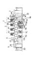
以下、本発明の実施の形態を図に基づいて説明する。図1は本発明に係るコーティング装置を備えた枚葉輪転印刷機の側面図、図2は同じく枚葉輪転印刷機のローラの配列図、図3は同じく胴の着脱装置の側面図である。 Hereinafter, embodiments of the present invention will be described with reference to the drawings. FIG. 1 is a side view of a sheet-fed rotary printing press provided with a coating apparatus according to the present invention, FIG. 2 is an arrangement diagram of rollers of the sheet-fed rotary printing press, and FIG. 3 is a side view of a cylinder attaching / detaching device.
図1において、全体を符号1で示す枚葉輪転印刷機は、シート状物としての紙を給紙する給紙部2と、給紙された紙を印刷する印刷部3と、印刷された紙の表裏面にニスをコーティングするコーティング部4と、コーティングされた紙が排紙される排紙部5とによって構成されている。印刷部3は、4台の第1ないし第4の表面印刷ユニット6Aないし6Dと、4台の第1ないし第4の裏面印刷ユニット7Aないし7Dとによって構成されている。4台の表面印刷ユニット6Aないし6Dには、周面に紙をくわえる爪が設けられた倍径の圧胴10aと、この圧胴10aの上部において対向するゴム胴11aと、このゴム胴11aの上部において対向する版胴12aと、この版胴12aにインキを供給するインキ部13aと、版胴12aに水を供給する給水装置14aとがそれぞれ備えられている。4台の裏面印刷ユニット7Aないし7Dには、周面に紙をくわえる爪が設けられた倍径の圧胴10bと、この圧胴10bの下部において対向するゴム胴11bと、このゴム胴11bの下部において対向する版胴12bと、この版胴12bにインキを供給するインキ部13bと、版胴12bに水を供給する給水装置14bとがそれぞれ備えられている。
In FIG. 1, a sheet-fed rotary printing press denoted as a whole by reference numeral 1 includes a
このような構成において、給紙部2からフィーダボード15に供給された紙の先端は、スイング装置16にくわえられ、渡し胴17を介して第1の表面印刷ユニット6Aの圧胴10aの爪にくわえ替えられ、圧胴10aとゴム胴11aとの対向点を通過するときに表面に1色目が印刷される。次いで、表面に1色目が印刷された紙は、第1の裏面印刷ユニット7Aの圧胴10bにくわえ替えられ、圧胴10bとゴム胴11bとの対向点を通過するときに裏面に1色目が印刷される。順次、第2ないし第4の表面印刷ユニット6Bないし6Dおよび第2ないし第4の裏面印刷ユニット7Bないし7Dによって、表裏面に4色が印刷された紙は、後述するようにコーティングユニット4によって表裏面にニスがコーティングされる。コーティングされた紙は、排紙ユニット5の排紙チェーン19の排紙爪(図示せず)にくわえ替えられ、排紙チェーン19によって搬送された後、排紙パイル20上に落下し積載される。
In such a configuration, the leading edge of the paper supplied from the
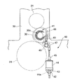
図2において、22はフィーダボード15の前端部に設けられたセンサーであって、フィーダボード15上の紙の有無を検出する。コーティングユニット4は、最終の裏面印刷ユニット7Dの圧胴10bに対向するゴム圧胴24と、印刷された紙の裏面をコーティングする第1のニスコーティング手段25と、印刷された紙の表面をコーティングする第2のニスコーティング手段26とによって構成されている。
In FIG. 2,
第1のニスコーティング手段25は、胴としての後述するゴム胴30と対向するゴム圧胴24と圧胴10bの対向点から紙搬送方向の上流側においてニス膜形成胴としてのゴム圧胴24と対向する第1のニス膜形成胴27と、この第1のニス膜形成胴27に対向するニス供給手段としての第1のアニロックスローラ28と、この第1のアニロックスローラ28にニスを供給するチャンバーコータ29とから構成されている。したがって、チャンバーコータ29から第1のアニロックスローラ28に供給されたニスは、第1のニス膜形成胴27を介してゴム圧胴24の周面に転移される。
The first varnish coating means 25 includes a
第2のニスコーティング手段26は、ゴム圧胴24と圧胴10bの対向点から紙搬送方向の下流側において胴としてのゴム圧胴24と対向するニス膜形成胴としてのゴム胴30と、このゴム胴30と対向する第2のニス膜形成胴31と、この第2のニス膜形成胴31に対向するニス供給手段としての第2のアニロックスローラ32と、この第2のアニロックスローラ32にニスを供給するチャンバーコータ33とから構成されている。したがって、チャンバーコータ33から第2のアニロックスローラ32に供給されたニスは、第2のニス膜形成胴31を介してゴム胴30に転移され、このゴム胴30とゴム圧胴24の対向点を通過する印刷された紙の表面にコーティングされる。このゴム胴30とゴム圧胴24の対向点を紙が通過するときに、ゴム胴30の印圧によって上述した第1のニスコーティング手段25の第1のニス膜形成胴27からゴム圧胴24の周面に転移されたニスが、印刷された紙の裏面にコーティングされる。したがって、ゴム圧胴24は、第2のコーティング手段26によって紙の表面をコーティングするときには紙を搬送する圧胴として機能し、このときにはゴム胴30がニス膜形成胴として機能する。また、ゴム圧胴24は、第1のコーティング手段25によって紙の裏面をコーティングするときには紙を搬送するニス膜形成胴として機能し、このときにはゴム胴30が印圧胴として機能する。
The second varnish coating means 26 includes a
次に、図3を用いて第1のニスコーティング手段25における第1のニス膜形成胴27の胴入れ、胴抜きを行う胴着脱装置および第2のニスコーティング手段26におけるゴム胴30の胴入れ、胴抜きを行う胴着脱装置について説明する。これら胴着脱装置は共に同じ構造であるため、ここではゴム胴30の胴入れ、胴抜きを行う胴着脱装置40についてのみ詳細に説明し、第1のニス膜形成胴27の胴入れ、胴抜きを行う胴着脱装置については必要に応じて概略を説明する。
Next, referring to FIG. 3, the first varnish
ゴム圧胴24と第2のニス膜形成胴31との両端軸は、フレーム39に図示をしない軸受を介して回転自在に軸支されている。また、ゴム胴30の両端軸30aは、左右のフレーム39に嵌着された偏心軸受41に回転自在に軸支されている。ゴム圧胴24の端軸に近接して片側のフレーム39から外方へ突設されたスタッド42には、ブラケット43が支持されており、このブラケット43には、駆動装置としてのステッピングモータ44が駆動ロッド45を直立させて固定されている。ステッピングモータ44を駆動させてナット44aを回転させることにより、このナット44aにねじ部を螺合させた駆動ロッド45が上下に進退するように構成されている。駆動ロッド45の上方に位置して左右のフレーム39に両端部を軸支されたレバー軸46の突出部には、正面視をL字状に形成された連結レバー47が軸着されている。
Both end shafts of the
前記偏心軸受41は、フレーム39の軸受孔に嵌着されたハウジングに、針状ころを介してハウジングと嵌合する外輪と、これに円錐ころを介して回転自在に嵌合された内輪(いずれも図示せず)とで形成されている。このような偏心軸受41の外輪に固定された軸受レバー48と前記連結レバー47とはロッド49で連結されており、前記ステッピングモータ44の駆動により駆動ロッド45を進退させ、連結レバー47とロッド49および軸受レバー48を経て偏心軸受41が回動するように構成されている。
The
偏心軸受41を構成する内輪内周面の軸芯と、偏心軸受41の外輪外周面の軸芯とは、互いに所定の寸法だけ偏心されている。すなわち、ゴム胴30の胴入れ状態から、ステッピングモータ44のロッド45を後退させることにより、内輪内周面の軸芯が外輪外周面の軸心を中心として移動する。この結果、ゴム胴30とゴム圧胴24との間に隙間が形成され胴抜きが行われる。なお、ゴム胴30と第2のニス膜形成胴31とは互いの周面が対向された状態が維持されている。一方、第1のニスコーティング手段25の第1のニス膜形成胴27の偏心軸受(図示せず)にも、ステッピングモータ44の駆動によりこの偏心軸受を回動させる同じ機構が備えられている。したがって、この第1のニスコーティング手段25の第1のニス膜形成胴27においても、ステッピングモータ44を回転させ偏心軸受を回動させることにより、第1のニス膜形成胴27とゴム圧胴24との間に隙間が形成され胴抜きが行われる。
The axis of the inner peripheral surface of the inner ring constituting the
次に、図2を用いて第1のニスコーティング手段25の第1のアニロックスローラ28の第1のニス膜形成胴27に対する着または離間を行う第1のローラ着脱装置50Aと、第2のニスコーティング手段26の第2のアニロックスローラ32の第2のニス膜形成胴31に対する着または離間を行う第2のローラ着脱装置50Bについて説明する。先ず、第1のローラ着脱装置50Aについて説明する。すなわち、第1のニスコーティング手段25の第1のアニロックスローラ28は偏心軸受28aを介してフレーム39に回動自在に支持されており、この偏心軸受28aの外輪には軸受レバー53Aの基端部が固定されている。この軸受レバー53Aの揺動端部は、シリンダエンドをフレーム39に枢着されたエアーシリンダ51Aのロッド52Aに枢着されている。
Next, referring to FIG. 2, the first roller attaching / detaching
55Aは電磁弁であって、この電磁弁55Aを作動させることにより、エアーシリンダ52Aへのエアーの供給を図示を省略したポートにより切り替え、軸受レバー53Aを介して第1のアニロックスローラ28を第1のニス膜形成胴27に対して着または離間を行う。したがって、この第1のアニロックスローラ28の第1のニス膜形成胴27に対する着または離間を行う第1のローラ着脱装置50Aの動作は、上述した第1のニスコーティング手段25における第1のニス膜形成胴27の胴入れ、胴抜きの動作とは別に行えるように構成されている。
55A is an electromagnetic valve. By operating the
次に、第2のローラ着脱装置50Bについて説明する。すなわち、第2のニスコーティング手段26の第2のアニロックスローラ32は偏心軸受32aを介してフレーム39に回動自在に支持されており、この偏心軸受32aの外輪には軸受レバー53Bの基端部が固定されている。この軸受レバー53Bの揺動端部は、シリンダエンドをフレーム39に枢着されたエアーシリンダ51Bのロッド52Bに枢着されている。55Bは電磁弁であって、この電磁弁55Bを作動させることにより、エアーシリンダ52Bへのエアーの供給を図示を省略したポートにより切り替え、軸受レバー53Bを介して第2のアニロックスローラ32を第2のニス膜形成胴31に対して着または離間を行う。したがって、この第2のアニロックスローラ32の第2のニス膜形成胴31に対する着または離間を行う第2のローラ着脱装置50Bの動作は、上述した第2のニスコーティング手段26におけるゴム胴30の胴入れ、胴抜きの動作とは別に行えるように構成されている。以上説明した印刷装置は、従来から知られている枚葉輪転印刷機のコーティング装置と格別変わるところはない。
Next, the second roller attaching / detaching
本発明の特徴とするところは、第1のニス膜形成胴27に対する第1のアニロックスローラ28の着のタイミングと、第2のニス膜形成胴31に対する第2のアニロックスローラ32の着のタイミングとを制御装置57によって制御する点にある。すなわち、符号56で示すロータリーエンコーダーは、1色目の印刷ユニット6Aの圧胴10aに設けられており、この圧胴10aの回転量を検出する。このロータリーエンコーダー56は、給紙部2からフィーダーボード15に給紙された最初の紙が渡し胴17の爪から1色目の印刷ユニット6Aの圧胴10aの爪にくわえ替えられることにより作動を開始する。
The feature of the present invention is that the
最初の紙が2色目以降の印刷ユニット7Aないし7Dおよび印刷ユニット6Bないし6Dの直前に搬送されることにより、ロータリーエンコーダー56の検出量により制御装置57においては、これら印刷ユニット7Aないし7Dおよび印刷ユニット6Bないし6Dの圧胴10bに対するゴム胴11bの胴入れと圧胴10aに対するゴム胴11aの胴入れを順次行うように制御する。
When the first paper is conveyed immediately before the
ここで、最初の紙がコーティングユニット4の直前まで送られてくると、制御装置57においては第1のニス膜形成胴27の胴入れとゴム胴30の胴入れ以前に、第1のニス膜形成胴27に対する第1のアニロックスローラ28の着動作と第2のニス膜形成胴31に対する第2のアニロックスローラ32の着動作とを先行して行うように制御する。
Here, when the first paper is sent to the position immediately before the
すなわち、この制御装置57による第1のアニロックスローラ28の着動作のタイミングは、ゴム圧胴24とゴム胴30とが着するときに、第1のアニロックスローラ28からゴム圧胴24へこのゴム圧胴24の2周分以上に相当する膜厚のニスがゴム圧胴24とゴム胴30とが対向する位置で最初の紙に対して供給されるように、第1のローラ着脱装置50Aによって第1のアニロックスローラ28を制御するように構成されている。つまり、ゴム圧胴24にゴム胴30が胴入れする時点で、ゴム圧胴24の周面に、第1のニス膜形成胴27からゴム圧胴24にニスが供給される開始点Aから1周分(点Aから点A)の長さと、ニス塗布点Bまで(点Aから点B)の長さ分のニスが塗布されているように、第1のニス膜形成胴27に第1のアニロックスローラ28が着するタイミングを制御装置57によって制御している。換言すれば、ゴム圧胴24にゴム胴30が胴入れするときには、第1のアニロックスローラ28から第1のニス膜形成胴27を介してゴム圧胴24へ供給されたニスの量はゴム圧胴24の2周分以上に相当する膜厚になっている。
That is, the timing of the operation of the
また、制御装置57による第2のアニロックスローラ32の着動作のタイミングは、ゴム圧胴24とゴム胴30とが着するときに、第2のアニロックスローラ32から第2のニス膜形成胴31を介してゴム胴30へこのゴム胴30の2周分以上に相当する膜厚のニスがゴム圧胴24とゴム胴30とが対向する位置で最初の紙に対して供給されるように、第2のローラ着脱装置50Bによって第2のアニロックスローラ32を制御するように構成されている。すなわち、ゴム圧胴24にゴム胴30が胴入れする時点で、ゴム胴30の周面に、第2のニス膜形成胴31からゴム胴30にニスが供給される開始点Cから1周分(点Cから点C)の長さと、ニス塗布点Bまで(点Cから点B)の長さ分のニスが塗布されているように、第2のニス膜形成胴31に第2のアニロックスローラ32が着するタイミングを制御装置57によって制御している。換言すれば、ゴム圧胴24にゴム胴30が胴入れするときには、第2のアニロックスローラ32から第2のニス膜形成胴31を介してゴム胴30へ供給されたニスの量がゴム胴30の2周分以上に相当する膜厚になっている。
The
このように構成されていることにより、最初の紙がコーティングユニット4のゴム圧胴24と圧胴30の間を通過する直前には、ゴム圧胴24の点Bから点Aまでの範囲の周面にはゴム圧胴24の2周分以上に相当する膜厚のニスが供給され、ゴム胴30の点Bから点Cまでの範囲の周面にはゴム胴30の2周分以上に相当する膜厚のニスが供給されている。したがって、最初の紙がゴム圧胴24と圧胴30との間を通過するときには、ゴム圧胴24と圧胴30とから充分の量のニスがコーティングされるため、最初の紙にもかかわらずゴム胴30の印圧によってコーティングされるニスが乾燥するようなことがない。したがって、ゴム圧胴24およびゴム胴30のブランケットに紙が張り付いてしまうことに起因して発生するゴム圧胴24のくわえ爪によって搬送される紙の損傷を防止できるとともに、ゴム圧胴24のくわえ爪から紙が外れたり、脱落した紙による機械の故障も防止することができる。
With this configuration, immediately before the first paper passes between the
以上説明した本実施の形態においては、第1および第2のアニロックスローラ28,32の着動作のタイミングを、ゴム圧胴24およびゴム胴30に2周分以上に相当する膜厚のニスが供給されるように制御装置57によって制御するようにしたが、2ないし6周分に相当する膜厚のニスが供給されるようにしてもよい。また、最初の紙に供給するニスの量が多過ぎることに起因する乾燥不良やブランケット上でのニス余りが発生する場合には、第1および第2のアニロックスローラ28,32の着動作のタイミングを遅らせることにより解消することが可能である。
In the present embodiment described above, the varnish having a film thickness corresponding to two or more rounds is supplied to the
また、印刷の条件または紙、インキ、ニス等の印刷資材の条件等に基づいて、予め第1および第2のアニロックスローラ28,32の着動作のタイミングのパターンを複数設け、これらを設定可能とすることにより、ニスの安定供給までの時間をより短縮することができるとともにニス供給の自動化が可能になる。また、本実施の形態においては、紙の表裏両面をコーティングするコーティング装置の例を説明したが、片面をコーティングするコーティング装置、すなわち第1のニスコーティング手段25のみや、第2のニスコーティング手段26のみが設けられたコーティング装置にも適用できる。また、第2のニスコーティング手段26のニス膜形成胴をゴム胴30と第2のニス膜形成胴31との2つとしたが、第1のニスコーティング手段25と同様に1つとしてもよく、また3つ以上としてもよい。また、ニスコーティングユニットとして、チャンバーコータ29,33からアニロックスローラ28,32にニスを供給するようにしたが、ニス舟内のニスに周面の一部を浸漬する元ローラによってニスを引き上げるようにしてもよい。
Also, based on the printing conditions or the conditions of printing materials such as paper, ink, varnish, etc., a plurality of patterns of timings for the first and
また、本実施の形態においては、コーティング装置を枚葉輪転印刷機の印刷部3と排紙部5との間に設けたコーティングユニットとしたが、独立したニス塗り機内等に設けたコーティングユニットとしてもよい。また、本実施の形態は、両面コーティング装置において、圧胴としてゴムが巻かれたゴム圧胴としたが、片面コーティング装置の場合には圧胴としてもよい。また、シート状物として、紙を用いた例を示したが、塩化ビニールシートとしてもよい。
In the present embodiment, the coating apparatus is a coating unit provided between the
1…枚葉輪転印刷機、2…給紙装置、3…印刷部、4…コーティングユニット、22…センサー、24…ゴム圧胴、25…第1のニスコーティング手段、26…第2のニスコーティング手段、27…第1のニス膜形成胴、28…第1のアニロックスローラ、29,33…チャンバーコータ、30…ゴム胴、31…第2のニス膜形成胴、32…第2のアニロックスローラ、40…胴着脱装置、41…偏心軸受、50A…第1のローラ着脱装置、50B…第2のローラ着脱装置、51A,51B…エアーシリンダ、55A,55B…電磁弁、56…ロータリーエンコーダー、57…制御装置。
DESCRIPTION OF SYMBOLS 1 ... Sheet-fed rotary printing machine, 2 ... Paper feeder, 3 ... Printing part, 4 ... Coating unit, 22 ... Sensor, 24 ... Rubber impression cylinder, 25 ... 1st varnish coating means, 26 ... 2nd varnish coating Means 27: first varnish film forming cylinder, 28: first anilox roller, 29, 33 ... chamber coater, 30 ... rubber cylinder, 31 ... second varnish film forming cylinder, 32 ... second anilox roller, DESCRIPTION OF
Claims (6)
前記胴と前記ニス膜形成胴とが着するときに、前記ニス供給ローラから前記ニス膜形成胴へこのニス膜形成胴の2周分以上に相当する膜厚のニスが前記胴と前記ニス膜形成胴とが対向する位置で最初のシート状物に対して供給されるように、前記ローラ着脱装置によって前記ニス供給ローラを制御する制御装置を備えたことを特徴とするコーティング装置。 A varnish supply roller for supplying varnish, at least one varnish film forming cylinder to which the varnish is supplied from the varnish supply roller, a cylinder facing the varnish film formation cylinder, and the varnish by attaching the varnish supply roller A coating apparatus for coating a sheet-like material passing between the varnish film forming cylinder and the cylinder, comprising a roller attaching / detaching device for supplying varnish to the film forming cylinder;
When the cylinder and the varnish film forming cylinder are attached, the varnish having a film thickness corresponding to two or more rounds of the varnish film forming cylinder is transferred from the varnish supply roller to the varnish film forming cylinder. A coating apparatus, comprising: a control device that controls the varnish supply roller by the roller attaching / detaching device so that the first sheet-like material is supplied at a position facing the forming cylinder.
前記制御装置は、前記胴と前記ニス膜形成胴とが着するときに、前記ニス供給ローラから前記ニス膜形成胴へこのニス膜形成胴の6周分以下に相当する膜厚のニスが前記胴と前記ニス膜形成胴とが対向する位置で最初のシート状物に対して供給されるように、前記ローラ着脱装置によって前記ニス供給ローラを制御することを特徴とするコーティング装置。 The coating apparatus according to claim 1.
When the cylinder and the varnish film forming cylinder are attached to the control device, the varnish having a film thickness corresponding to 6 laps or less of the varnish film forming cylinder is transferred from the varnish supply roller to the varnish film forming cylinder. The coating apparatus characterized by controlling the said varnish supply roller with the said roller attachment or detachment apparatus so that a cylinder and the said varnish film formation cylinder may be supplied with respect to the first sheet-like material.
前記胴はシート状物を搬送する圧胴であることを特徴とするコーティング装置。 The coating apparatus according to claim 1.
The said cylinder is an impression cylinder which conveys a sheet-like object, The coating apparatus characterized by the above-mentioned.
前記ニス膜形成胴はシート状物を搬送する胴であることを特徴とするコーティング装置。 The coating apparatus according to claim 1.
The coating apparatus according to claim 1, wherein the varnish film forming cylinder is a cylinder for conveying a sheet-like material.
前記胴を第2のニス供給ローラからニスが供給される少なくとも1つの第2のニス膜形成胴とし、前記第2のニス供給ローラを着させることにより前記第2のニス膜形成胴にニスを供給する第2のローラ着脱装置を備え、
前記制御装置は、前記第2のニス膜形成胴と前記ニス膜形成胴とが着するとき、前記第2のニス供給ローラから前記第2のニス膜形成胴へこの第2のニス膜形成胴の2周分以上に相当する膜厚のニスが前記第2のニス膜形成胴と前記ニス膜形成胴とが対向する位置で最初のシート状物に対して供給されるように、前記第2のローラ着脱装置によって前記第2のニス供給ローラを制御することを特徴とするコーティング装置。 The coating apparatus according to claim 1.
The cylinder is used as at least one second varnish film forming cylinder to which varnish is supplied from a second varnish supply roller, and the varnish is applied to the second varnish film forming cylinder by attaching the second varnish supply roller. A second roller attaching / detaching device for supplying,
When the second varnish film forming cylinder and the varnish film forming cylinder are attached to the control device, the second varnish film forming cylinder is transferred from the second varnish supply roller to the second varnish film forming cylinder. The second varnish is supplied to the first sheet-like material at a position where the second varnish film forming cylinder and the varnish film forming cylinder face each other. The second varnish supply roller is controlled by a roller attaching / detaching device.
前記制御装置は、前記ニス膜形成胴と前記第2のニス膜形成胴とが着するときに、前記第2のニス供給ローラから前記第2のニス膜形成胴へこの第2のニス膜形成胴の6周分以下に相当する膜厚のニスが前記第2のニス膜形成胴と前記ニス膜形成胴とが対向する位置で最初のシート状物に対して供給されるように、前記第2のローラ着脱装置によって前記第2のニス供給ローラを制御することを特徴とするコーティング装置。
The coating apparatus according to claim 5, wherein
When the varnish film forming cylinder and the second varnish film forming cylinder are attached, the control device forms the second varnish film from the second varnish supply roller to the second varnish film forming cylinder. The varnish having a film thickness corresponding to 6 cylinders or less of the cylinder is supplied to the first sheet-like material at a position where the second varnish film forming cylinder and the varnish film forming cylinder face each other. The coating apparatus according to claim 2, wherein the second varnish supply roller is controlled by two roller attaching / detaching devices.
Priority Applications (1)
| Application Number | Priority Date | Filing Date | Title |
|---|---|---|---|
| JP2004261478A JP4713113B2 (en) | 2004-09-08 | 2004-09-08 | Coating equipment |
Applications Claiming Priority (1)
| Application Number | Priority Date | Filing Date | Title |
|---|---|---|---|
| JP2004261478A JP4713113B2 (en) | 2004-09-08 | 2004-09-08 | Coating equipment |
Publications (2)
| Publication Number | Publication Date |
|---|---|
| JP2006076080A true JP2006076080A (en) | 2006-03-23 |
| JP4713113B2 JP4713113B2 (en) | 2011-06-29 |
Family
ID=36155940
Family Applications (1)
| Application Number | Title | Priority Date | Filing Date |
|---|---|---|---|
| JP2004261478A Expired - Fee Related JP4713113B2 (en) | 2004-09-08 | 2004-09-08 | Coating equipment |
Country Status (1)
| Country | Link |
|---|---|
| JP (1) | JP4713113B2 (en) |
Cited By (3)
| Publication number | Priority date | Publication date | Assignee | Title |
|---|---|---|---|---|
| US8042463B2 (en) | 2007-07-25 | 2011-10-25 | Tohoku Ricoh Co., Ltd. | Coating device and coating unit in a stencil printing apparatus |
| WO2013165567A1 (en) * | 2012-05-04 | 2013-11-07 | Unipixel Displays, Inc. | Manufacturing of high resolution conductive patterns using organometallic ink and banded anilox rolls |
| CN108405237A (en) * | 2018-05-24 | 2018-08-17 | 鑫鹏源(聊城)智能科技股份有限公司 | A kind of high-pressure airless oiling station to steel tube coupling spray painting |
Citations (4)
| Publication number | Priority date | Publication date | Assignee | Title |
|---|---|---|---|---|
| JPH10296953A (en) * | 1997-04-23 | 1998-11-10 | Komori Corp | Coating apparatus |
| JP2000289190A (en) * | 1999-04-08 | 2000-10-17 | Komori Corp | Coating apparatus |
| JP2003047897A (en) * | 2001-08-06 | 2003-02-18 | Mitsubishi Heavy Ind Ltd | Method and apparatus for attaching and detaching roll of coater |
| JP2003182031A (en) * | 2001-12-14 | 2003-07-03 | Komori Corp | Coating apparatus |
-
2004
- 2004-09-08 JP JP2004261478A patent/JP4713113B2/en not_active Expired - Fee Related
Patent Citations (4)
| Publication number | Priority date | Publication date | Assignee | Title |
|---|---|---|---|---|
| JPH10296953A (en) * | 1997-04-23 | 1998-11-10 | Komori Corp | Coating apparatus |
| JP2000289190A (en) * | 1999-04-08 | 2000-10-17 | Komori Corp | Coating apparatus |
| JP2003047897A (en) * | 2001-08-06 | 2003-02-18 | Mitsubishi Heavy Ind Ltd | Method and apparatus for attaching and detaching roll of coater |
| JP2003182031A (en) * | 2001-12-14 | 2003-07-03 | Komori Corp | Coating apparatus |
Cited By (6)
| Publication number | Priority date | Publication date | Assignee | Title |
|---|---|---|---|---|
| US8042463B2 (en) | 2007-07-25 | 2011-10-25 | Tohoku Ricoh Co., Ltd. | Coating device and coating unit in a stencil printing apparatus |
| WO2013165567A1 (en) * | 2012-05-04 | 2013-11-07 | Unipixel Displays, Inc. | Manufacturing of high resolution conductive patterns using organometallic ink and banded anilox rolls |
| GB2515934A (en) * | 2012-05-04 | 2015-01-07 | Unipixel Displays Inc | Manufacturing of high resolution conductive patterns using organometallic ink and banded anilox rolls |
| US9504164B2 (en) | 2012-05-04 | 2016-11-22 | Eastman Kodak Company | Manufacturing of high resolution conductive patterns using organometallic ink and banded anilox rolls |
| GB2515934B (en) * | 2012-05-04 | 2017-08-09 | Eastman Kodak Co | Manufacturing of high resolution conductive patterns using organometallic ink and banded anilox rolls |
| CN108405237A (en) * | 2018-05-24 | 2018-08-17 | 鑫鹏源(聊城)智能科技股份有限公司 | A kind of high-pressure airless oiling station to steel tube coupling spray painting |
Also Published As
| Publication number | Publication date |
|---|---|
| JP4713113B2 (en) | 2011-06-29 |
Similar Documents
| Publication | Publication Date | Title |
|---|---|---|
| US6338299B1 (en) | Sheet-like material printing and coating system and method | |
| JP2001526133A (en) | How to print on a sheet | |
| JP2003182031A (en) | Coating apparatus | |
| JP2006250202A (en) | Rotary drive transmission device for roller | |
| JP5497270B2 (en) | Liquid transfer device | |
| JP2006297734A (en) | Air blowing device of printing machine | |
| JP4713113B2 (en) | Coating equipment | |
| JP6310321B2 (en) | Printing machine and cleaning method thereof | |
| JP2008023998A (en) | Coding performed by embossing equipment | |
| JP3935797B2 (en) | Sheet-fed printing press | |
| US9027475B2 (en) | Method for changing edition on a rotary press | |
| JP2008105277A (en) | Operating method of printing machine, and printing machine | |
| JP4625286B2 (en) | Coating equipment | |
| JP5408892B2 (en) | Liquid transfer device | |
| JP4230604B2 (en) | Coating equipment | |
| JP2006231593A (en) | Printing machine or coating machine | |
| JP2018099898A (en) | Sheet printing machine | |
| JP4452284B2 (en) | Sheet-fed printing press | |
| JP6384987B2 (en) | Sheet-fed printing press | |
| JP2009220401A (en) | Sheet delivery device of printing machine | |
| JP2003047897A (en) | Method and apparatus for attaching and detaching roll of coater | |
| JP2009190256A (en) | Printing machine | |
| JPH0324958A (en) | Varnish coating device of sheet printing machine | |
| JP2013241267A (en) | Conveyance device | |
| JP2006051650A (en) | Printer |
Legal Events
| Date | Code | Title | Description |
|---|---|---|---|
| A621 | Written request for application examination |
Free format text: JAPANESE INTERMEDIATE CODE: A621 Effective date: 20070724 |
|
| A977 | Report on retrieval |
Free format text: JAPANESE INTERMEDIATE CODE: A971007 Effective date: 20091221 |
|
| A131 | Notification of reasons for refusal |
Free format text: JAPANESE INTERMEDIATE CODE: A131 Effective date: 20100105 |
|
| A521 | Written amendment |
Free format text: JAPANESE INTERMEDIATE CODE: A523 Effective date: 20100308 |
|
| A02 | Decision of refusal |
Free format text: JAPANESE INTERMEDIATE CODE: A02 Effective date: 20101019 |
|
| A521 | Written amendment |
Free format text: JAPANESE INTERMEDIATE CODE: A523 Effective date: 20110118 |
|
| A911 | Transfer of reconsideration by examiner before appeal (zenchi) |
Free format text: JAPANESE INTERMEDIATE CODE: A911 Effective date: 20110131 |
|
| A01 | Written decision to grant a patent or to grant a registration (utility model) |
Free format text: JAPANESE INTERMEDIATE CODE: A01 Effective date: 20110301 |
|
| A61 | First payment of annual fees (during grant procedure) |
Free format text: JAPANESE INTERMEDIATE CODE: A61 Effective date: 20110324 |
|
| LAPS | Cancellation because of no payment of annual fees |